Article

Mechanical Properties and In Vitro Corrosion Behaviors of Biodegradable Magnesium Alloy Suture Anchors

1
School of Health Science and Engineering, University of Shanghai for Science and Technology, Shanghai 200093, China
2
Shanghai Innovation Medical Technology Co., Ltd., Shanghai 201306, China
*
Authors to whom correspondence should be addressed.
Metals 2024, 14(3), 288; https://doi.org/10.3390/met14030288
Submission received: 3 February 2024 / Revised: 24 February 2024 / Accepted: 27 February 2024 / Published: 29 February 2024
(This article belongs to the Special Issue Advanced Biomedical Materials (2nd Edition))

Abstract

:
Biodegradable suture anchors based on Mg-Nd-Zn-Zr alloy were developed for ligament-to-bone fixation in rotator cuff surgeries. The Mg alloy anchors were designed with structural features of narrow tooth and wide tooth, and simulated through finite element analysis (FEA). Meanwhile, the corrosion behaviors of the Mg alloy anchors were studied by immersion test and the mechanical properties were investigated by measuring the maximum torque and pull-out force. The simulation result showed that the wide-tooth anchor exhibited more a uniform stress distribution and lower shear stress in the torsion process, suggesting a satisfactory torsional resistance of this structure. Meanwhile, the wide-tooth anchor exhibited a lower Von-Mises stress after applying the same pull-out force in the simulation, indicating a higher resistance to pull-out failure of the anchor. The result of the immersion test indicated that the wide-tooth anchor exhibited a slightly slower corrosion rate in Hank’s solution after 14-day immersion, which was beneficial to enhance the structural and mechanical stability of the biodegradable suture anchor. Furthermore, the results of the mechanical properties test demonstrated that the wide-tooth anchor showed superior performance with higher maximum torques and axial pull-out forces before and after corrosion. More importantly, the axial pull-out force and maximum torque for the wide-tooth anchor decreased by 5.86% and 8.64% after corrosion, which were significantly less than those for the narrow-tooth anchor. Therefore, the wide-tooth suture anchor with lower corrosion rate, higher mechanical properties and structural stability is a promising candidate for ligament-bone fixation in the repair of rotator cuff injuries.

1. Introduction

Tendon and ligament injuries account for more than 30% of musculoskeletal diseases, with approximately 4,000,000 new cases worldwide every year, which seriously affect people’s health and quality of life [1,2]. The standard surgical intervention for tendon and ligament injuries involves ligation of the torn tendon and fixation of the affected joint for several weeks to restore the integrity of tissue. In clinical practice, suture anchors have been used for the repair of tendon and ligament injuries by compressing the soft tissue against the humeral surface, and then the torn tendon and ligament can be fixed at its appropriate attachment point, enabling close adherence to the bone and facilitating tendon–bone fusion [3].
Currently, biomaterials used to fabricate suture anchors can be classified into two types: non-absorbable and absorbable [4]. The non-absorbable materials include titanium (Ti) and its alloys, and polyetheretherketone (PEEK). Ti-based anchors with a high modulus may create a stress shielding effect during load transfer between the implant and bone interface, which is unfavorable for the growth and repair of bones [2]. Furthermore, the long-term presence of Ti-based anchors can lead to postoperative complications such as rejection and chronic inflammation. On the other hand, the radiolucency of suture anchors fabricated from PEEK may complicate their repositioning in cases of displacement or dislodgment [5,6]. In an ideal clinical scenario, a suture anchor should be able to disappear completely after its function has been completed [4,7]. Therefore, a biodegradable suture anchor becomes one choice. However, biodegradable polymers with insufficient mechanical properties cannot meet the requirements of surgical implants for load-bearing applications [8].
Compared to polymers, the high mechanical strength and fracture toughness of Mg alloys make them more suitable for load-bearing applications such as bone plates and screws, tissue scaffolds and joint replacement [9,10,11]. As the lightest structural metal, Mg alloys exhibit similar elasticity to bone and can degrade completely in the human body; they are more suitable for developing biodegradable suture anchors without additional surgery to remove them after their period of use [12,13,14]. Furthermore, Mg could stimulate bone formation during the degradation process [12]. Ma et al. [2] reported that the ZE21C suture anchor promoted bone healing above the suture anchor and regeneration of the fibrocartilage interface of the ligament–bone junction. Chen et al. [15] developed a high-purity Mg suture anchor for sheep rotator cuff repair that provided reliable anchoring function within 12 weeks with no toxic effects on animal organs. It is well accepted that the structure design determines the performance of a biodegradable suture anchor by means of affecting its corrosion behaviors and mechanical properties [16,17,18]. A biomechanical investigation of suture anchors found that the pull-out strength was positively correlated with the contact surface area between the anchor screw thread and the surrounding bone [17]. Furthermore, the interaction between devices and the surrounding tissue at the implant interface is essential for success or failure of implants. As an implantable tissue fixation device, it is necessary to optimize the tooth structure of a Mg-based suture anchor to enhance the mechanical properties during the processes of pulling out and torsion, and reduce the corrosion rate, which highly affects the outcomes of tissue repair and healing.
In this study, two suture anchors based on biodegradable Mg-Nd-Zn-Zr alloy were designed with different structural features of wide-tooth and narrow-tooth, and the pull-out force and torsion of the anchor were analyzed through finite element analysis. Additionally, the corrosion behaviors of the Mg alloy suture anchors in terms of hydrogen evolution and corrosion rate were evaluated through in vitro immersion tests. Furthermore, the maximum torque and the axial pull-out force of the suture anchors before and after corrosion were also studied through mechanical testing equipment.

2. Materials and Methods

2.1. Structural Design of Mg Suture Anchor

The suture anchors utilized in this study were fabricated from Mg-2.8Nd-0.2Zn-0.4Zr (wt.%) alloy supplied by Shanghai Innovation Medical Technology Co., Ltd., Shanghai, China. The design of anchors adhered to the specifications illustrated in Figure 1, featuring a total length of 18.8 mm, a shaft outer diameter of 4.5 mm and a pitch of 1.6 mm. Before experiment, all samples underwent a pre-cleaning process using anhydrous ethanol followed by washing with distilled water to ensure optimal cleanliness.

2.2. Finite Element Analysis of Mg Suture Anchor

The 3D structural model of the suture anchor was established using SolidWorks 2023 SP0.1 software and imported into the ANSYS Workbench 2023 R1 platform. The material parameters for the polyurethane block and Mg Alloy were added to the engineering data listed in detail in Table 1.
Meshing of suture anchor and the polyester block was carried out in the meshing module, using ten-node tetrahedral cells. A cell size of 0.15 mm was employed for the threaded surfaces of both the anchors and polyester blocks. The anchor model consisted of approximately 200,000 nodes, while the polyester block model had roughly 300,000 nodes.
According to YY/T 1867-2023 [21], the bone drill matching the anchor specification was utilized to prefabricate the necessary holes in the polyester block. To simulate the actual application scenario, inserts and anchors of the suture anchor were employed together under rotation in the torsion model. A distal displacement with zero degrees of freedom was applied to the end of anchor, while a clockwise torque of 0.2 Nm was applied to the six inner surfaces to calculate the maximum Von-Mises and shear stresses on the anchor.
The pull-out simulation model consisted of a Mg alloy suture anchor and a high-density polyurethane block. Considering the extraction speed is relative and slow, the simulation can be regarded as a static load. The model was established with frictional contact, utilizing a friction coefficient of 0.2. The polyester block was fixed. After that, upward forces of 100, 200 and 300 N were exerted on the overline hole of the anchor. The distributions of equivalent stress and strain for anchors were observed under different pull-out forces to determine the various responses of the suture anchor during axial pull-out.

2.3. In Vitro Corrosion Experiments of Mg Suture Anchor

The surface areas were 397 mm2 and 402 mm2 for the narrow-tooth and wide-tooth anchors, and the volume of solution was calculated based on a volume-to-sample area ratio of 1 mL·mm−2, which was in conformation with ASTMG F3268 [22]. The suture anchors were suspended vertically in Hank’s solution, and the volume of hydrogen gas produced by the samples was collected using an acid buret, kept at a temperature of 37 °C and buffered at pH 7.4 ± 0.02 for a duration of 14 days. The volume of hydrogen gas was recorded at 24 h intervals, and the solution was replaced with a fresh one every 48 h. After 14-day immersion, the samples were cleaned for removing the corrosion products using a standard chromium trioxide (CrO3) solution recommended in ASTM G1-90 [23]. The hydrogen evolution and weight loss were measured repeatedly by 5 samples and the average corrosion rate was calculated by the following equation:
CR = 95.03 × VH/(A × T × D)
CR = (8.76 × 10⁴ × W)/(A × T × D)
where VH (mL) is the amount of hydrogen produced, W (g) is the weight change before and after immersion, A (cm2) is surface area of the Mg alloy suture anchors, T (h) is the immersion time, and D (g/cm3) is the density of the Mg-Nd-Zn-Zr alloy.
After degradation for 14 days, the surface morphologies of the suture anchors were documented and analyzed. The corrosion morphologies of the suture anchor samples were observed using a field emission scanning electron microscopy (FE-SEM, Gemini SEM 300, ZEISS, Baden-Wurttemberg, Germany). Element contents were analyzed using energy dispersion spectroscopy (EDS, Aztec X-Manx 80, Oxford Instruments, Oxford, UK) equipped with SEM.

2.4. Pull-Out Force and Torsion Tests of Mg Suture Anchor

To assess the performance of the experimental structures, a PBSC-RP30 Splice Screw Performance Tester was employed. During the pull-out trial, a hole was pre-drilled into the synthetic bone and a tap was used to create a threaded channel. Suture anchors, equipped with #2 suture threads, were screwed in and firmly secured. A controlled pulling force was applied at a speed of 5 mm/minute to simulate realistic conditions and evaluate the anchoring performance of the sutures. The failure of anchor was anticipated, either through extraction from the solid bone or suture breakage. The maximum load experienced during this process was recorded which was regarded as an essential indicator of the pull-out strength.
In the torsion test, one end of the insert was securely fastened to the testing equipment, while the suture anchor was secured at the opposing end. Torque was gradually applied at an appropriate speed (3 mm/min) and the highest achieved torque was documented. Throughout the test, a constant axial preload load of 3.00 N was maintained, while the rotation rate remained at a constant of 3 revolutions per minute.

3. Results

3.1. FEA of Mg Suture Anchor

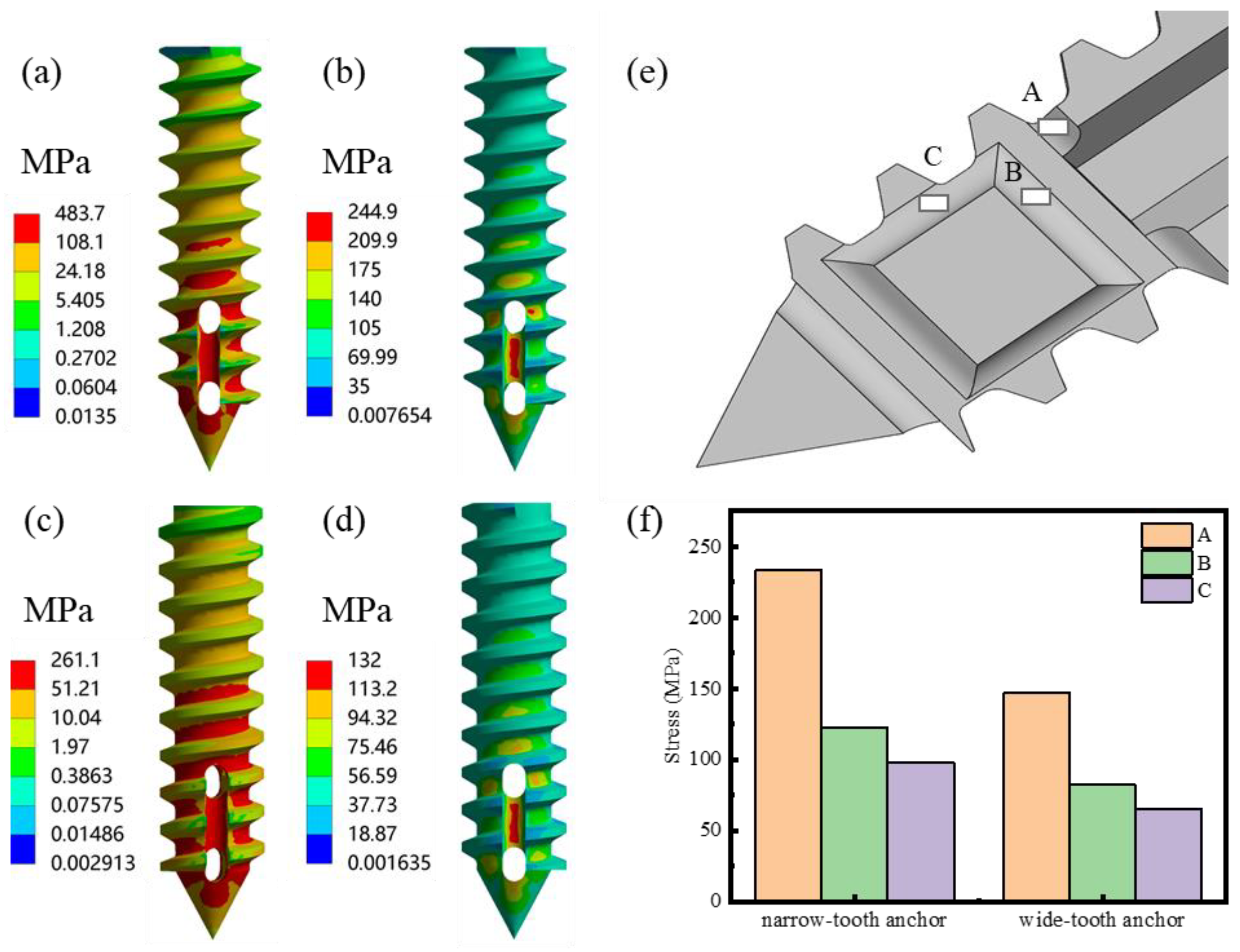
The simulation results of the anchor in the torsion process are presented in Figure 2a–d, which show the distributions of Von-Mises and shear stress with the application of 0.2 Nm torque to the anchor. It was obvious that the narrow-tooth anchor experienced a maximum shear stress of 244.9 MPa and a maximum Von-Mises stress of 483.67 MPa. However, the local maximum Von-Mises stress exceeded the yield strength of the material, indicating a high risk of damage of the narrow-tooth anchor in the process of torsion. Conversely, the wide-tooth anchor experienced a maximum shear stress of 92.36 MPa and a maximum Von-Mises stress of 261.13 MPa, with the local maximum Von-Mises stress within the acceptable range of the material, suggesting the satisfactory torsional resistance and strength of the anchor with the wide-tooth structure. However, the distribution of stress on the anchor was not even, with greater stress created around the screw holes for the two groups. Based on the maximum Von-Mises stress, three points of A, B and C on the anchor (Figure 2e) were selected for further analysis, and the simulated numerical results during the torsion process are displayed in Figure 2f. Following the application of 0.2 Nm torque to the anchors, the narrow-tooth anchor exhibited a higher maximum equivalent stress (233.41, 122.17 and 97.99 MPa) compared to the wide-tooth anchor (147.09, 82.35 and 65.37 MPa) at the same corresponding points, suggesting that the design of the wide-tooth anchor could effectively decrease the stress concentration. It was worth noting that point A exhibited the maximum stress concentration level for both of the anchors, representing the most vulnerable point initiating the failure of the device during the torsion process.
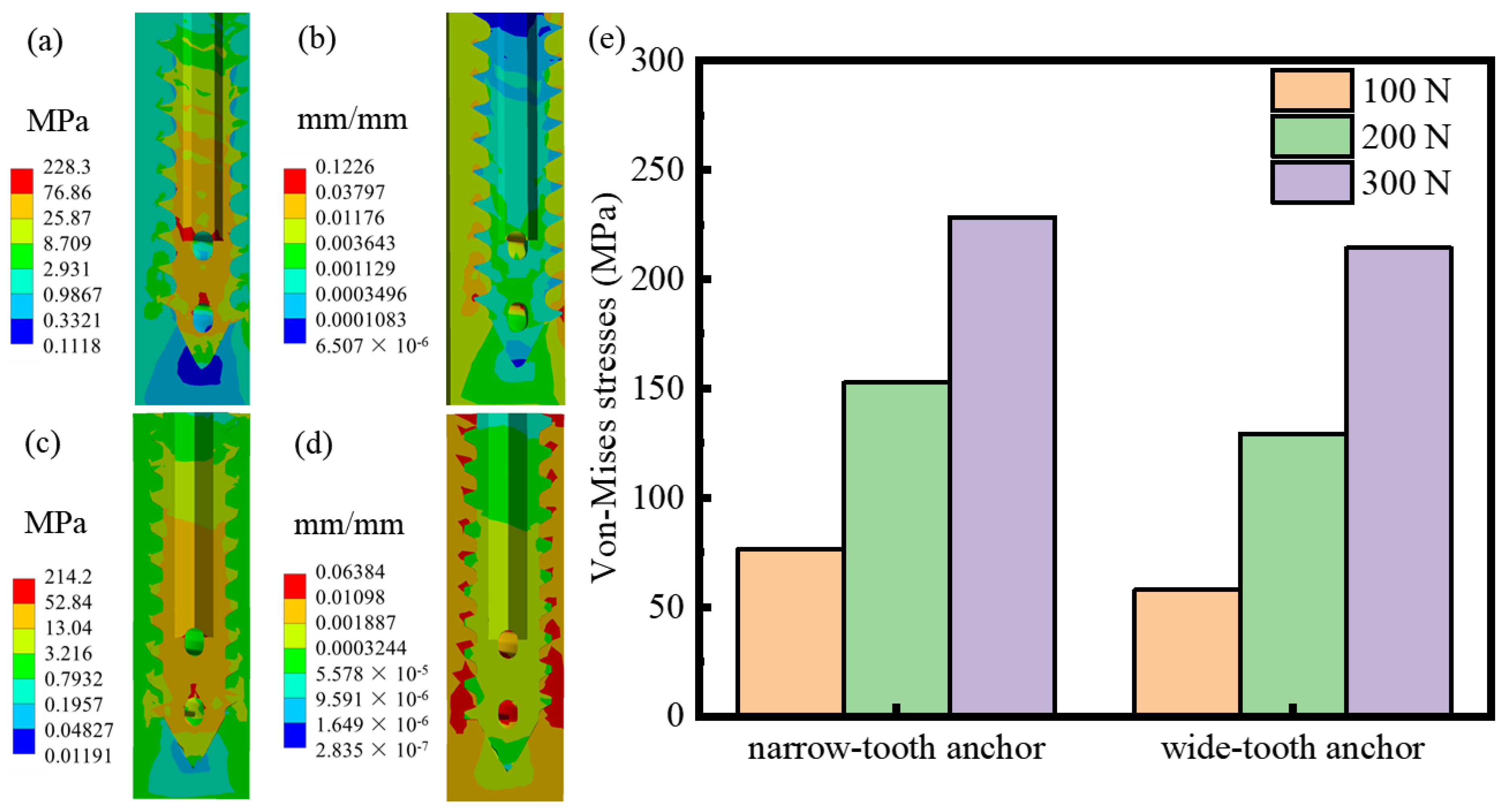
Figure 3a–d show the stress distribution on the anchor under a pull-out force of 300 N. The narrow-tooth anchor exhibited a maximum Von-Mises stress of 228.34 MPa and an equivalent elastic strain of 0.12 mm, while the wide-tooth anchor displayed a lower maximum Von-Mises stress of 214.21 MPa and an equivalent elastic strain of 0.06 mm. Meanwhile, the distributions of Von-Mises stress on the anchor under the two pull-out forces of 100 N and 200 N were also analyzed through FEA, and the results are shown in Figure 3e. It was obvious that the Von-Mises stress increased with the increasing of pull-out force and the wide-tooth anchor exhibited a lower Von-Mises stress under the same pull-out force condition, indicating a higher resistance to the pull-out failure of the anchor.

3.2. In Vitro Corrosion Properties of Mg Suture Anchor

The Mg alloy suture anchors were immersed in Hank’s solution for 14 days to investigate the corrosion properties in terms of variation in pH value, hydrogen evolution and corrosion rate, as displayed in Figure 4. The pH values showed a fluctuation around 8.3 during the 14-day immersion for the two groups (Figure 4a). The result from Figure 4b indicates that the variation tendency of hydrogen evolution for the two anchors was relatively close. Figure 4c indicates that the corrosion rate of the wide-tooth anchor (0.069 ± 0.019 mm/y) was slightly lower than that of the narrow-tooth anchor (0.073 ± 0.011 mm/y) based on the calculations of hydrogen evolution, while, from a weight loss point of view, the corrosion rates were 0.086 ± 0.011 mm/y and 0.090 ± 0.018 mm/y for the wide-tooth and narrow-tooth anchors, respectively, which was consistent with the results calculated by hydrogen evolution. Therefore, the results from the immersion test including variation in pH value, hydrogen evolution and corrosion rate revealed that the wide-tooth anchor exhibited a lower corrosion rate as compared with the narrow-tooth anchor, which was beneficial to enhance the structural and mechanical stability of the biodegradable suture anchor during the service of the device. The difference in corrosion rates for the two groups can probably be attributed to the reason that the individual narrow-tooth structure which is sharper and smaller in size is inherently more prone to corrosion.
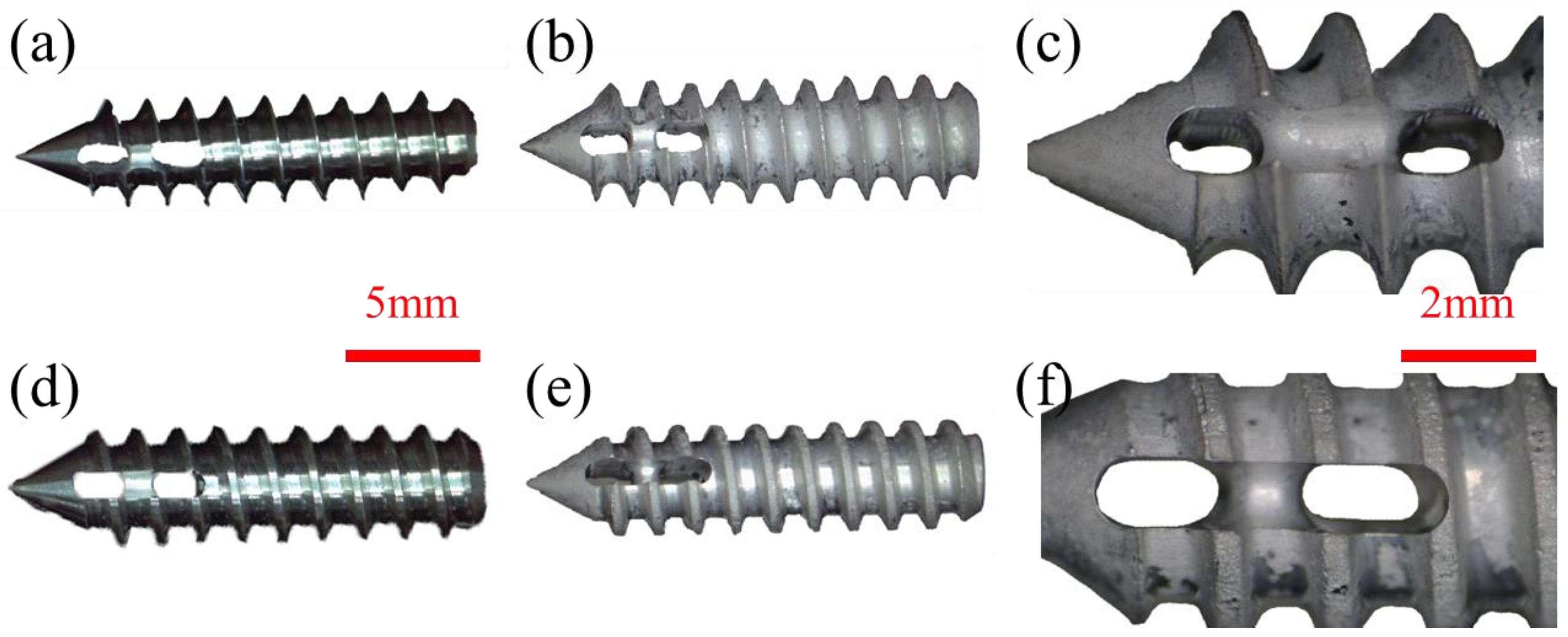
The micrographs of the Mg alloy suture anchors before and after 14-day immersion in Hank’s solution and cleaning are shown in Figure 5. It was obvious that the structures of the two anchors appeared to have remained intact and the corrosion surfaces were smooth after corrosion (Figure 5b,e). From the detailed morphological examinations of the two anchors (Figure 5c,f), no significant corrosion pits were found in the devices. The result can be attributed to the slight potential difference between the second phase of Mg12Nd formed in the Mg-Nd-Zn-Zr alloy and the α-Mg matrix [24], which is anticipated to lead to an improvement in surface stability and a homogeneous corrosion surface on the suture anchors.
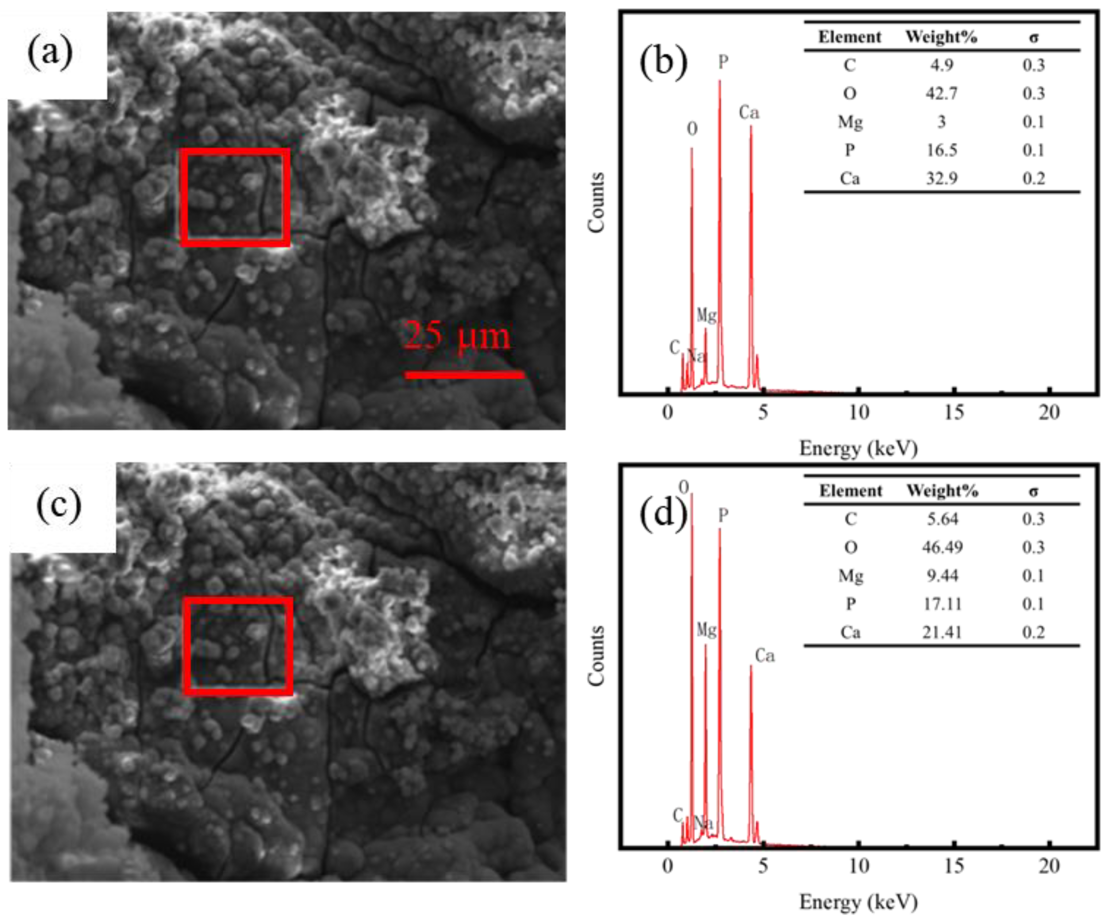
The SEM images and EDS results of the corrosion products on the two suture anchors are shown in Figure 6. It was obvious that numerous granular corrosion products were deposited on the surface, and the corrosion product layers exhibited obvious cracks for the two groups (Figure 6a,c). The EDS results revealed that the corrosion products consisted of C, O, Mg, P and Ca, and the contents of Mg and P for the wide-tooth anchor are higher than those of the narrow-tooth anchor (Figure 6b,d). It was reported that the accumulation of the P element could help to delay the degradation of Mg alloys [2]. Therefore, higher content of the P element in corrosion products is beneficial to improve the corrosion resistance of the wide-tooth anchor, which is consistent with the results of variation in pH value, hydrogen evolution and corrosion rate in Figure 4.

3.3. Pull-Out and Torsion Tests of Mg Suture Anchor

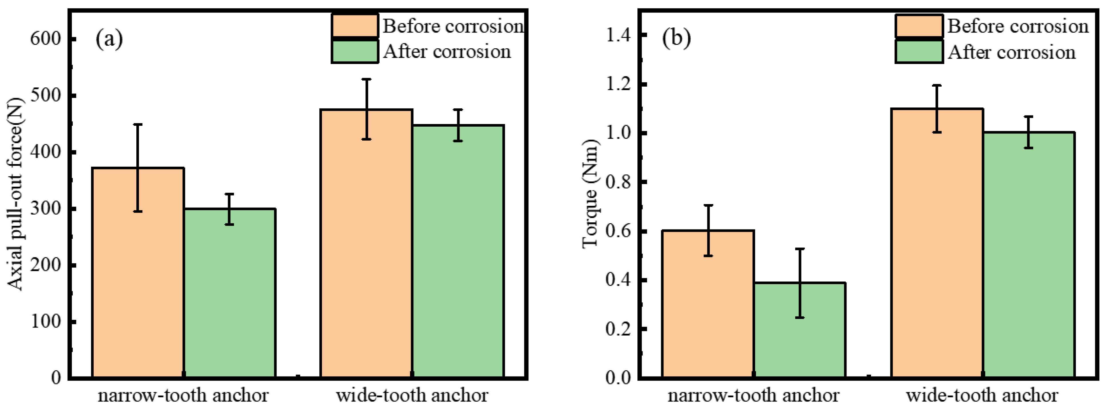
The results of the pull-out force of the Mg alloy suture anchors before and after corrosion are shown in Figure 7a. It was observed that the pull-out forces of the wide-tooth anchor before and after corrosion were 475.59 ± 53.36 N and 447.73 ± 27.60 N, respectively, which were higher than those of the narrow-tooth anchor (372.05 ± 77.07 N and 299.05 ± 26.73 N). Obviously, the pull-out force of the wide-tooth anchor decreased 5.86% after corrosion, which is lower than that of the narrow-tooth anchor that decreased 19.62%. The results demonstrated that the wide-tooth anchor exhibited a superior resistance to pull-out failures and maintained a stronger connection between the anchor and the polyester block.
The results of maximum torque for the Mg alloy suture anchors before and after corrosion are shown in Figure 7b. The maximum torques of the wide-tooth anchors were 1.099 ± 0.10 Nm and 1.004 ± 0.06 Nm before and after corrosion, which were significantly higher than those of the narrow-tooth anchors (0.603 ± 0.10 Nm and 0.388 ± 0.14 Nm). Obviously, the maximum torque of the wide-tooth anchor decreased 8.64% after corrosion, which is lower than that of the narrow-tooth anchor that decreased 35.66%. Generally, a suture anchor with a higher maximum torque is helpful to enhance the fixation strength between the device and target tissue, and thus improve the safety of the surgery. Therefore, the wide-tooth anchor with a higher maximum torque appears to be a preferable choice over the narrow-tooth anchor.
The micrographs of the Mg alloy suture anchors before and after 14-day immersion in Hank’s solution and subsequent cleaning, following pull-out and torsion tests, are displayed in Figure 8. It was evident that the structures of both anchors exhibited fractures at the suture hole locations after the torsion tests (Figure 8a,b,e,f). No significant deformation or cracks were observed in the structures of either anchor following the pull-out tests (Figure 8c,d,g,h). These findings were corroborated by finite element simulation results and the torsional fractures can be attributed to stress concentration.

4. Discussion

Conventional bio-inert materials composed of metal or non-degradable polymer are broadly used to develop suture anchors for the repair of rotator cuff injury, enabling tissue reduction and fixation due to the high mechanical strength and fracture toughness [25,26,27,28]. However, the mechanical shunt produced by conventional anchors can cause bone loss over time, resulting in decreased bone strength and delayed tissue healing [29]. Furthermore, the permanent placement implants may cause some adverse effects such as infections or irritations, while removing these implants requires secondary surgery [30].
Magnesium (Mg) and its alloys appear to be promising candidates for the application of orthopedic implants due to the combination of biodegradability, biocompatibility and Young’s modulus close to cortical bone [4,12]. However, Mg alloys show vulnerability to corrosion for physiological application, with the degradation leading to both a premature loss of mechanical integrity and delay of the healing processes locally [24,31]. The corrosion of Mg alloys in the physical environment is actually determined by the electrochemical reaction between Mg and water [19]:
Mg → Mg2+ + 2e (anodic reaction)
2H2O + 2e → H2 + 2OH (cathodic reaction)
The overall reaction can be expressed as follows:
Mg + 2H2O → Mg (OH)2 + H2
Mg (OH)2 is generally insoluble in water. However, body fluids are rich in acid ions (i.e., CO32−, PO43− and Cl); the existence of Cl could transform insoluble Mg(OH)2 into soluble MgCl2, then the chemical reaction could be carried out by the following equation:
Mg (OH)2 +2Cl → MgCl2 + 2OH
Previous studies have shown that Mg-Nd-Zn-Zr alloy presents a lower degradation rate, excellent biocompatibility and long-term structural and mechanical durability in vivo, and is regarded as an ideal material for developing orthopedic implants [19,24].
Structure is an important parameter for adapting the load-bearing medical device to mechanical property needs in a desired lifetime [32,33]. In this study, two suture anchors based on Mg-Nd-Zn-Zr alloy were designed with different tooth structures, and the mechanical properties and in vitro corrosion behaviors of the Mg alloy anchors were studied by FEA and experiment. The results suggested that the wide-tooth anchor exhibited superior pull-out and torsional performances compared to the narrow-tooth anchor (Figure 7), which can be attributed to a larger contact area of the wide-tooth anchor with surrounding tissue and a more uniform stress distribution on the anchor during the pull-out and torsion processes, thereby reducing stress concentration and enhancing the axial pull-out and torsional resistance of the anchor [34,35]. Furthermore, the wide-tooth structure can bear more load and improve the anti-torsion ability of the anchor. However, the axial pull-out force and maximum torque of the wide-tooth anchor decreased after it was corroded in Hank’s solution for 14 days. This can be attributed to the reason that the mechanical properties of Mg alloy implants in a physiological environment are influenced by the corrosion which results in a gradual loss in both the structural integrity and the mass of the implants [19]. In addition, the corrosion of the Mg alloy leads to cracks on the surface (Figure 6a,c), which further reduces the axial pull-out force and maximum torque of the anchor. Although the mechanical properties of both anchors are decreased by corrosion, the degree varies with 5.86% of axial pull-out force and 8.64% of maximum torque for the wide-tooth anchor, which is significantly lower than those of the narrow-tooth anchor (19.62% of axial pull-out force and 35.66% of maximum torque), indicating that the wide-tooth design is superior to the narrow-tooth design in maintaining structural and mechanical stability and preventing performance failure of the anchor during the service process.
A suture anchor is responsible for the fixed function of the implant which should facilitate optimal integration into the surrounding tissues [36]. Figure 9 shows the simplified force analysis of the anchor during the pull-out process. When a pull-out force is applied, the anchor is subjected to a pull force which can be indicated as fpull-out, and a friction between the anchor and the polyester block (indicated as fanchor) can be generated under these circumstances, as shown in Figure 9a. From the point of view of a single tooth, as compared to the narrow tooth, the wide tooth can provide a better fixing effect due to its larger surface area, consequently resulting in greater friction under the same fpull-out (Figure 9b,c). In other words, a more stable fixing effect can be obtained by the anchor with a wide tooth structure. Furthermore, under the same fpull-out, the stress distribution on the unit area of a single wide tooth is smaller and more uniform, which makes the wide-tooth anchor possesses stronger resistance to damage and deformation [37]. In orthopedic applications, implant devices are exposed to physiologically stressed environments and usually subjected to acute dynamic loadings during normal physical activities, leading to corrosion fatigue and stress corrosion cracking (SCC) [29]. FEA results indicated that narrow-tooth anchors exhibited higher and more concentrated stress distribution, subsequently accelerating corrosion rates and resulting in a diminished pull-out force and torque performance. Therefore, the wide-tooth anchor with a smaller and more uniform stress distribution has advantages in maintaining mechanical integrity to avoid the early failure of the device during the healing period.
This study primarily focuses on the mechanical properties and in vitro degradation behaviors of the suture anchors fabricated from Mg-Nd-Zn-Zr alloy. Animal experiments will be scheduled to verify the effectiveness of the Mg alloy suture anchors in terms of interactions with biological organisms and the long-term structural stability of the device. In addition, this study confirmed the superiority of the wide-tooth anchor over the narrow-tooth anchor, while the detailed structure parameters of the wide-tooth anchor should be further optimized to improve its comprehensive performances.

5. Conclusions

In this study, biodegradable suture anchors based on Mg-Nd-Zn-Zr alloy were developed for the repair of rotator cuff injury. In vitro corrosion behaviors and mechanical properties of the suture anchors were studied by FEA and experiment. The main conclusions can be drawn as follows:
(1)
The simulation results of the torsion and pull-out tests showed that the wide-tooth anchor exhibited a lower shear stress (132 MPa) of 0.2 Nm and less equivalent elastic strain (0.06 mm) under a pull-out force of 300 N than those of the narrow-tooth anchor (244.9 MPa and 0.12 mm).
(2)
The corrosion rate of the wide-tooth anchor (0.086 ± 0.011 mm/y) in Hank’s solution after 14-day immersion was slightly slower than that of the narrow-tooth anchor (0.090 ± 0.018 mm/y).
(3)
The maximum torques of the wide-tooth anchor before and after corrosion were 1.099 ± 0.10 Nm and 1.004 ± 0.06 Nm, which were much higher than those of the narrow-tooth anchor (0.603 ± 0.10 Nm and 0.388 ± 0.14 Nm). Moreover, the axial pull-out forces of the wide-tooth anchor before and after corrosion were 475.59 ± 53.36 N and 447.73 ± 27.60 N, which were also higher than those of the narrow-tooth anchor (372.05 ± 77.07 N and 299.05 ± 26.73 N).
(4)
The axial pull-out force and maximum torque for the wide-tooth anchor decreased by 5.86% and 8.64% after corrosion, which were significantly less than those for the narrow-tooth anchor (19.62% of axial pull-out force and 35.66% of maximum torque).
Therefore, the wide-tooth suture anchor with lower corrosion rate, higher mechanical properties and structural stability is a promising candidate for ligament–bone fixation in the repair of rotator cuff injuries.

Author Contributions

Conceptualization, L.M. and J.Z.; methodology, L.M.; software, Z.D. and X.C.; validation, L.M., J.Z. and C.S.; formal analysis, Z.D., X.C. and Z.H.; investigation, J.Z.; resources, L.M.; data curation, Z.D., X.C. and Z.H.; writing—original draft preparation, Z.D., X.C. and Z.H.; writing—review and editing, L.M., J.Z. and C.S.; visualization, Z.D. and Z.H.; supervision, L.M.; project administration, L.M. and J.Z.; funding acquisition, L.M. and C.S. All authors have read and agreed to the published version of the manuscript.

Funding

This work was supported by the National Natural Science Foundation of China (Grant Nos.: 51901137, 51735003) and the National Key R&D Program of the Ministry of Science and Technology—digital medical equipment R&D (Grant No.: 2019YFC0120402).

Data Availability Statement

The original contributions presented in the study are included in the article, further inquiries can be directed to the corresponding authors.

Conflicts of Interest

Author Jian Zhang was employed by the company Shanghai Innovation Medical Technology Co., Ltd. The remaining authors declare that the re-search was conducted in the absence of any commercial or financial relationships that could be construed as a potential conflict of interest.

References

  1. Lim, W.L.; Liau, L.L.; Ng, M.H.; Chowdhury, S.R.; Law, J.X. Current Progress in Tendon and Ligament Tissue Engineering. Tissue Eng. Regen. Med. 2019, 16, 549–571. [Google Scholar] [CrossRef] [PubMed]
  2. Ma, D.; Wang, J.; Zheng, M.; Zhang, Y.; Huang, J.; Li, W.; Ding, Y.-X.; Zhang, Y.; Zhu, S.; Wang, L.; et al. Degradation Behavior of Ze21c Magnesium Alloy Suture Anchors and Their Effect on Ligament-Bone Junction Repair. Bioact. Mater. 2023, 26, 128–141. [Google Scholar] [CrossRef] [PubMed]
  3. Takeda, Y.; Fujii, K.; Suzue, N.; Miyatake, K.; Kawasaki, Y.; Yokoyama, K. Repair Tension During Arthroscopic Rotator Cuff Repair Is Correlated with Preoperative Tendon Retraction and Postoperative Rotator Cuff Integrity. Arthrosc. J. Arthrosc. Relat. Surg. 2021, 37, 2735–2742. [Google Scholar] [CrossRef] [PubMed]
  4. Cho, C.-H.; Bae, K.-C.; Kim, D.-H. Biomaterials Used for Suture Anchors in Orthopedic Surgery. Clin. Orthop. Surg. 2021, 13, 287. [Google Scholar] [CrossRef]
  5. Kim, K.E. The Development of Biodegradable Metallic Screws and Suture Anchors for Soft Tissue Fixation in Orthopaedic Surgery; University of Pittsburgh: Pittsburgh, PA, USA, 2015. [Google Scholar]
  6. Ro, K.; Pancholi, S.; Son, H.S.; Rhee, Y.G. Perianchor Cyst Formation after Arthroscopic Rotator Cuff Repair Using All-Suture–Type, Bioabsorbable-Type, and Peek-Type Anchors. Arthrosc. J. Arthrosc. Relat. Surg. 2019, 35, 2284–2292. [Google Scholar] [CrossRef]
  7. Huang, B.; Yang, M.; Kou, Y.; Jiang, B. Absorbable Implants in Sport Medicine and Arthroscopic Surgery: A Narrative Review of Recent Development. Bioact. Mater. 2024, 31, 272–283. [Google Scholar] [CrossRef]
  8. Chung, S.W.; Oh, K.-S.; Kang, S.J.; Yoon, J.P.; Kim, J.Y. Clinical Outcomes of Arthroscopic Rotator Cuff Repair Using Poly Lactic-Co-Glycolic Acid Plus Β-Tricalcium Phosphate Biocomposite Suture Anchors. Clin. Shoulder Elb. 2018, 21, 22. [Google Scholar] [CrossRef]
  9. Peng, B.; Xu, H.; Song, F.; Wen, P.; Tian, Y.; Zheng, Y. Additive Manufacturing of Porous Magnesium Alloys for Biodegradable Orthopedic Implants: Process, Design, and Modification. J. Mater. Sci. Technol. 2023, 182, 79–110. [Google Scholar] [CrossRef]
  10. Witte, F. Biodegradable Metals. In Biomaterials Science; Elsevier: Amsterdam, The Netherlands, 2020; pp. 271–287. [Google Scholar]
  11. Sezer, N.; Evis, Z.; Kayhan, S.M.; Tahmasebifar, A.; Koç, M. Review of Magnesium-Based Biomaterials and Their Applications. J. Magnes. Alloys 2018, 6, 23–43. [Google Scholar] [CrossRef]
  12. Wang, J.-L.; Xu, J.-K.; Hopkins, C.; Chow, D.H.-K.; Qin, L. Biodegradable Magnesium-Based Implants in Orthopedics—A General Review and Perspectives. Adv. Sci. 2020, 7, 1902443. [Google Scholar] [CrossRef]
  13. Dong, H.; Lin, F.; Boccaccini, A.R.; Virtanen, S. Corrosion Behavior of Biodegradable Metals in Two Different Simulated Physiological Solutions: Comparison of Mg, Zn and Fe. Corros. Sci. 2021, 182, 109278. [Google Scholar] [CrossRef]
  14. Maier, P.; Hort, N. Magnesium Alloys for Biomedical Applications. Metals 2020, 10, 1328. [Google Scholar] [CrossRef]
  15. Chen, Y.; Sun, Y.; Wu, X.; Lou, J.; Zhang, X.; Peng, Z. Rotator Cuff Repair with Biodegradable High-Purity Magnesium Suture Anchor in Sheep Model. J. Orthop. Transl. 2022, 35, 62–71. [Google Scholar] [CrossRef] [PubMed]
  16. Barber, F.A.; Herbert, M.A.; Beavis, R.C.; Oro, F.B. Suture Anchor Materials, Eyelets, and Designs: Update 2008. Arthrosc. J. Arthrosc. Relat. Surg. 2008, 24, 859–867. [Google Scholar] [CrossRef] [PubMed]
  17. Chae, S.-W.; Kang, J.-Y.; Lee, J.; Han, S.-H.; Kim, S.-Y. Effect of Structural Design on the Pullout Strength of Suture Anchors for Rotator Cuff Repair. J. Orthop. Res. 2018, 36, 3318–3327. [Google Scholar] [CrossRef]
  18. Daher, M.; Zalaquett, Z.; Fares, M.Y.; Boufadel, P.; Khanna, A.; Abboud, J.A. Osteoporosis in the Setting of Rotator Cuff Repair: A Narrative Review. Shoulder Elb. 2023, 14, 17585732231207338. [Google Scholar] [CrossRef]
  19. Mao, L.; Zheng, X.; Tian, Y.; Shi, Y.; Zhang, X.; Song, C. Structural Optimization, Fabrication, and Corrosion Behaviors of Biodegradable Mg-Nd-Zn-Zr Alloy Hemostatic Clip. Metals 2022, 12, 1979. [Google Scholar] [CrossRef]
  20. Bevill, G.; Keaveny, T.M. Trabecular Bone Strength Predictions Using Finite Element Analysis of Micro-Scale Images at Limited Spatial Resolution. Bone 2009, 44, 579–584. [Google Scholar] [CrossRef]
  21. YY/T 1867-2023; Sports Medicine Implants Wired Anchor. State Drug Administration: Beijing, China, 2023.
  22. ASTM F3268-18; Standard Guide for in vitro Degradation Testing of Absorbable Metals. ASTM: West Conshohocken, PA, USA, 2018.
  23. ASTM G1-90; Standard Practice for Preparing, Cleaning, and Evaluating Corrosion Test Specimens. ASTM: West Conshohocken, PA, USA, 1999.
  24. Mao, L.; Zhou, H.; Chen, L.; Niu, J.; Zhang, L.; Yuan, G.; Song, C. Enhanced Biocompatibility and Long-Term Durability in Vivo of Mg-Nd-Zn-Zr Alloy for Vascular Stent Application. J. Alloys Compd. 2017, 720, 245–253. [Google Scholar] [CrossRef]
  25. Wang, D.; Zhang, X.; Huang, S.; Liu, Y.; Fu, B.S.-C.; Mak, K.K.-L.; Blocki, A.M.; Yung, P.S.-H.; Tuan, R.S. Engineering Multi-Tissue Units for Regenerative Medicine: Bone-Tendon-Muscle Units of the Rotator Cuff. Biomaterials 2021, 272, 120789. [Google Scholar] [CrossRef]
  26. Domb, A.; Mizrahi, B.; Farah, S. Biomaterials and Biopolymers; Springer Nature: Berlin/Heidelberg, Germany, 2023; Volume 7. [Google Scholar]
  27. Kim, T.; See, C.W.; Li, X.; Zhu, D. Orthopedic Implants and Devices for Bone Fractures and Defects: Past, Present and Perspective. Eng. Regen. 2020, 1, 6–18. [Google Scholar] [CrossRef]
  28. Jin, W.; Chu, P.K. Orthopedic Implants. Encycl. Biomed. Eng. 2019, 1, 425–439. [Google Scholar]
  29. Lee, H.; Shin, D.Y.; Na, Y.; Han, G.; Kim, J.; Kim, N.; Bang, S.-J.; Kang, H.S.; Oh, S.; Yoon, C.-B. Antibacterial Pla/Mg Composite with Enhanced Mechanical and Biological Performance for Biodegradable Orthopedic Implants. Biomater. Adv. 2023, 152, 213523. [Google Scholar] [CrossRef]
  30. Amini, A.R.; Wallace, J.S.; Nukavarapu, S.P. Short-Term and Long-Term Effects of Orthopedic Biodegradable Implants. J. Long-Term Eff. Med. Implant. 2011, 21, 93–122. [Google Scholar] [CrossRef]
  31. Olugbade, T.O.; Omiyale, B.O.; Ojo, O.T. Corrosion, Corrosion Fatigue, and Protection of Magnesium Alloys: Mechanisms, Measurements, and Mitigation. J. Mater. Eng. Perform. 2021, 31, 1707–1727. [Google Scholar] [CrossRef]
  32. Nouri, A.; Shirvan, A.R.; Li, Y.; Wen, C. Biodegradable Metallic Suture Anchors: A Review. Smart Mater. Manuf. 2023, 1, 100005. [Google Scholar] [CrossRef]
  33. Weidling, M.; Heilemann, M.; Schoenfelder, S.; Heyde, C.E. Influence of Thread Design on Anchorage of Pedicle Screws in Cancellous Bone: An Experimental and Analytical Analysis. Sci. Rep. 2022, 12, 8051. [Google Scholar] [CrossRef]
  34. Song, F.; Feng, W.; Yang, D.; Li, G.; Iqbal, K.; Liu, Y.; Yang, H. A Novel Screw Modeling Approach to Study the Effects of Screw Parameters on Pullout Strength. J. Biomech. Eng. 2023, 145, 014502. [Google Scholar] [CrossRef]
  35. Al-Sanea, A.; Aktas, S.; Celik, T.; Kisioglu, Y. Effects of the Internal Contact Surfaces of Dental Implants on Screw Loosening: A 3-Dimensional Finite Element Analysis. J. Prosthet. Dent. 2023, 130, 603.e1–603.e11. [Google Scholar] [CrossRef]
  36. Damisih, D.; Hanafi, R.; Gumelar, M.D.; Sah, J.; Rahmania, A.W.; Gustiono, D.; Nurlina, N.; Arrifqi, M.H.; Setyadi, I.; Triwibowo, B. Pullout Strength Evaluation of Titanium Pedicle Screw in Different Grades of Polyurethane. AIP Conf. Proc. 2023, 2719, 030020. [Google Scholar]
  37. Zhang, C.; Zeng, C.; Wang, Z.; Zeng, T.; Wang, Y. Optimization of Stress Distribution of Bone-Implant Interface (Bii). Biomater. Adv. 2023, 147, 213342. [Google Scholar] [CrossRef] [PubMed]
Figure 1. Structure of the designed suture anchor: (a) the narrow-tooth anchor; (b) the wide-tooth anchor.
Metals 14 00288 g001
Figure 2. Simulation results of the suture anchors in the process of torsion: distributions of Von-Mises stress and shear stress on the narrow-tooth (a,b) and the wide-tooth (c,d) anchors; (e) feature points labeled on the suture anchor for force analysis; (f) results of the Von-Mises stress at different points on the suture anchors.
Metals 14 00288 g002
Figure 3. Simulation results of the suture anchors under a pull-out force of 300 N: distributions of Von-Mises stress and equivalent elastic strain of the narrow-tooth (a,b) and wide-tooth (c,d) anchors; (e) results of the maximum Von-Mises stress on the two suture anchors at different pull-out forces.
Metals 14 00288 g003
Figure 4. Immersion test of the Mg alloy suture anchors in Hanks’ solution for 14 days: (a) variations in pH value in Hanks’ solution; (b) volume of hydrogen evolution; (c) corrosion rates calculated by hydrogen evolution and weight loss.
Metals 14 00288 g004
Figure 5. Micrographs of Mg suture anchors before and after 14 days of immersion: (a,b) morphologies of the narrow-tooth anchor before and after corrosion; (c) detailed morphology of the narrow-tooth anchor after corrosion; (d,e) morphologies of the wide-tooth anchor before and after corrosion; (f) detailed morphology of the wide-tooth anchor after corrosion.
Metals 14 00288 g005
Figure 6. SEM images and EDS results of the Mg alloy suture anchors after 14-day corrosion: (a,b) narrow-tooth anchor; (c,d) wide-tooth anchor.
Metals 14 00288 g006
Figure 7. Pull-out and torsion tests of Mg alloy anchors before and after corrosion: (a) axial pull-out forces of the anchors; (b) maximum torques of the anchors.
Metals 14 00288 g007
Figure 8. Micrographs of Mg suture anchors before and after 14 days of immersion, following pull-out and torsion tests: (a,b) torsional morphologies of the narrow-tooth anchor before and after corrosion; (c,d) pull-out morphologies of the narrow-tooth anchor before and after corrosion; (e,f) torsional morphologies of the wide-tooth anchor before and after corrosion; (g,h) pull-out morphologies of the wide-tooth anchor before and after corrosion.
Metals 14 00288 g008
Figure 9. Force analysis of suture anchor during the pull-out process: (a) pull-out force applied to anchor; force analysis of single tooth for the narrow-tooth (b) and wide-tooth anchors (c).
Metals 14 00288 g009
Table 1. Mechanical parameters of simulated materials (Reprinted from Refs. [19,20]).
MaterialMaterial Parameters
Mg alloyρ = 1.78 g/cm3
E = 4.2 × 10¹⁰ Pa
ν = 0.35
σt = 3 × 10⁸ Pa
Polyester blockρ = 0.32 g/cm3
E = 2.67 × 10⁸ Pa
ν = 0.2
σy = 5.9 × 10⁶ Pa
Disclaimer/Publisher’s Note: The statements, opinions and data contained in all publications are solely those of the individual author(s) and contributor(s) and not of MDPI and/or the editor(s). MDPI and/or the editor(s) disclaim responsibility for any injury to people or property resulting from any ideas, methods, instructions or products referred to in the content.