
Effect of Al-Si Coating on the Interfacial Microstructure and Corrosion Resistance of Dissimilar Laser Al Alloy/22MnB5 Steel Joints

 ,
,
Abstract
:1. Introduction
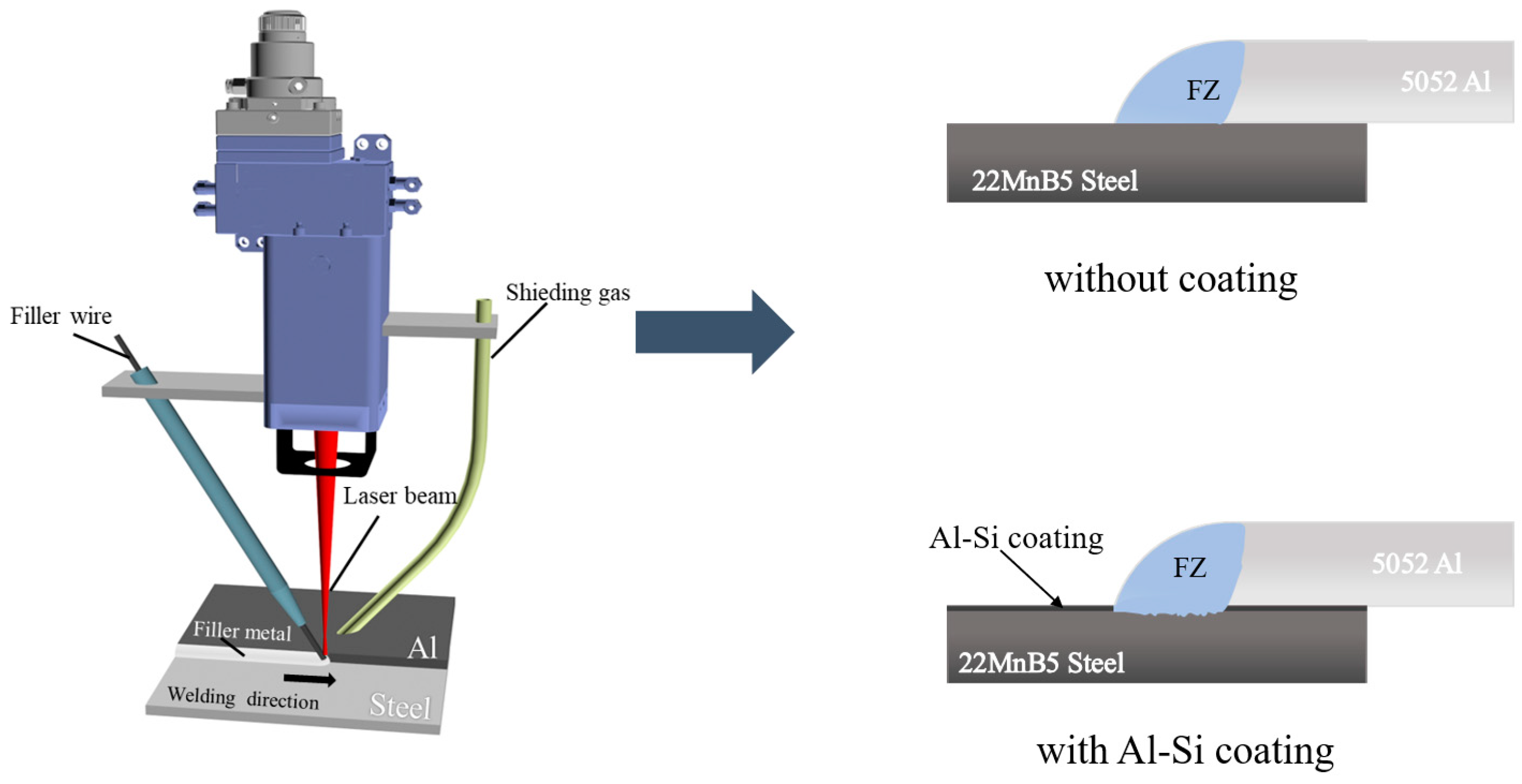
2. Experimental Design
3. Results and Discussion
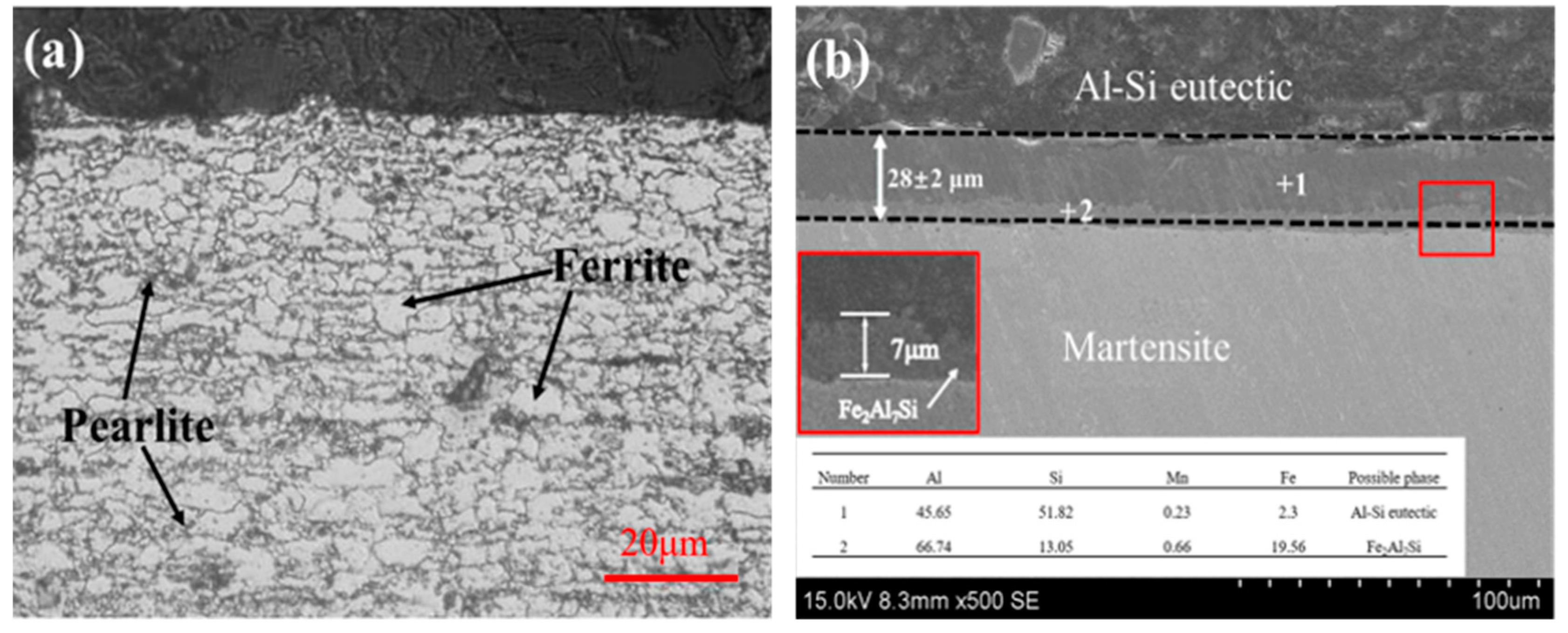
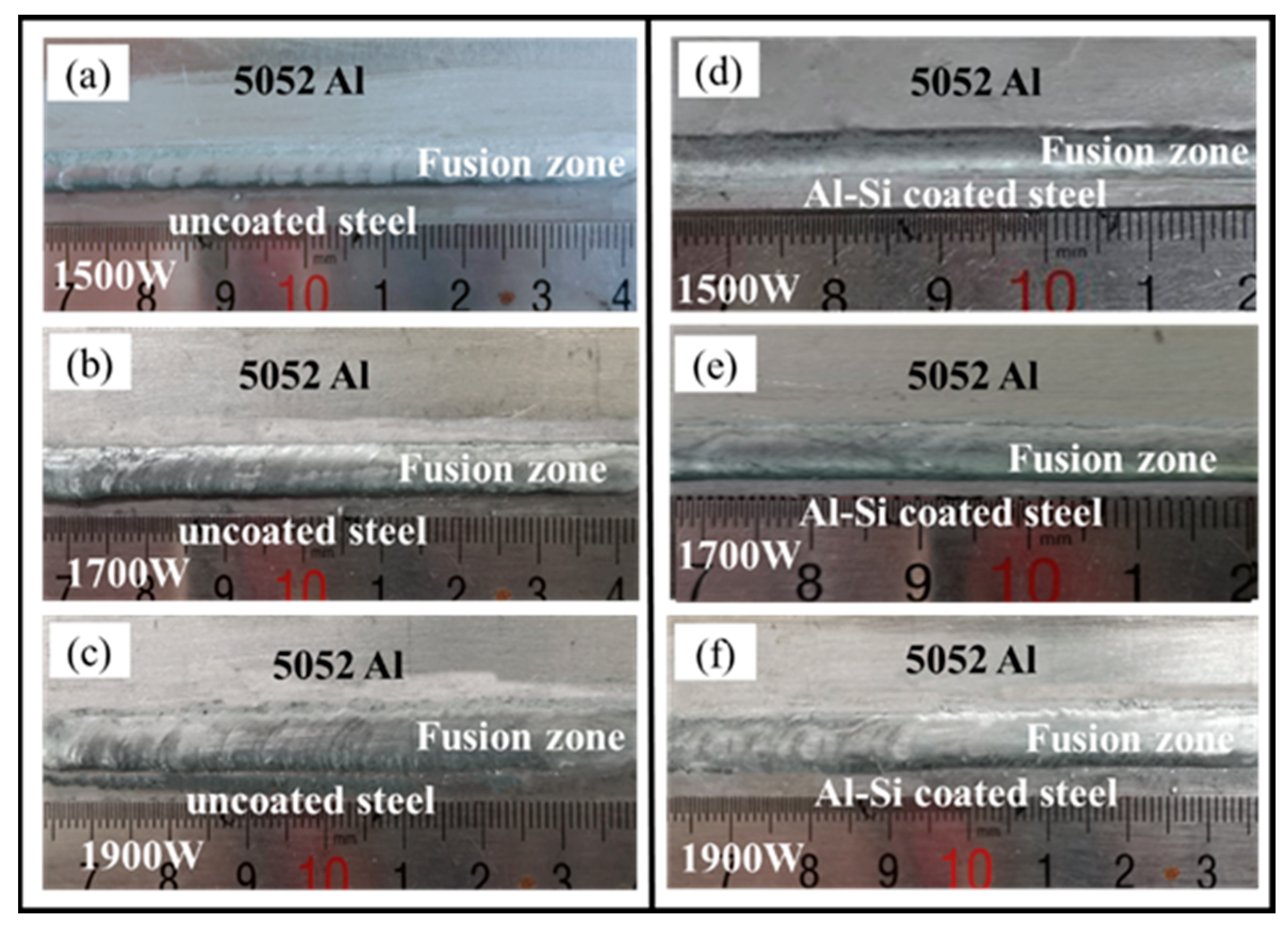
3.1. Macroscopic Morphology and Interfacial Microstructure
3.2. Corrosion Resistance
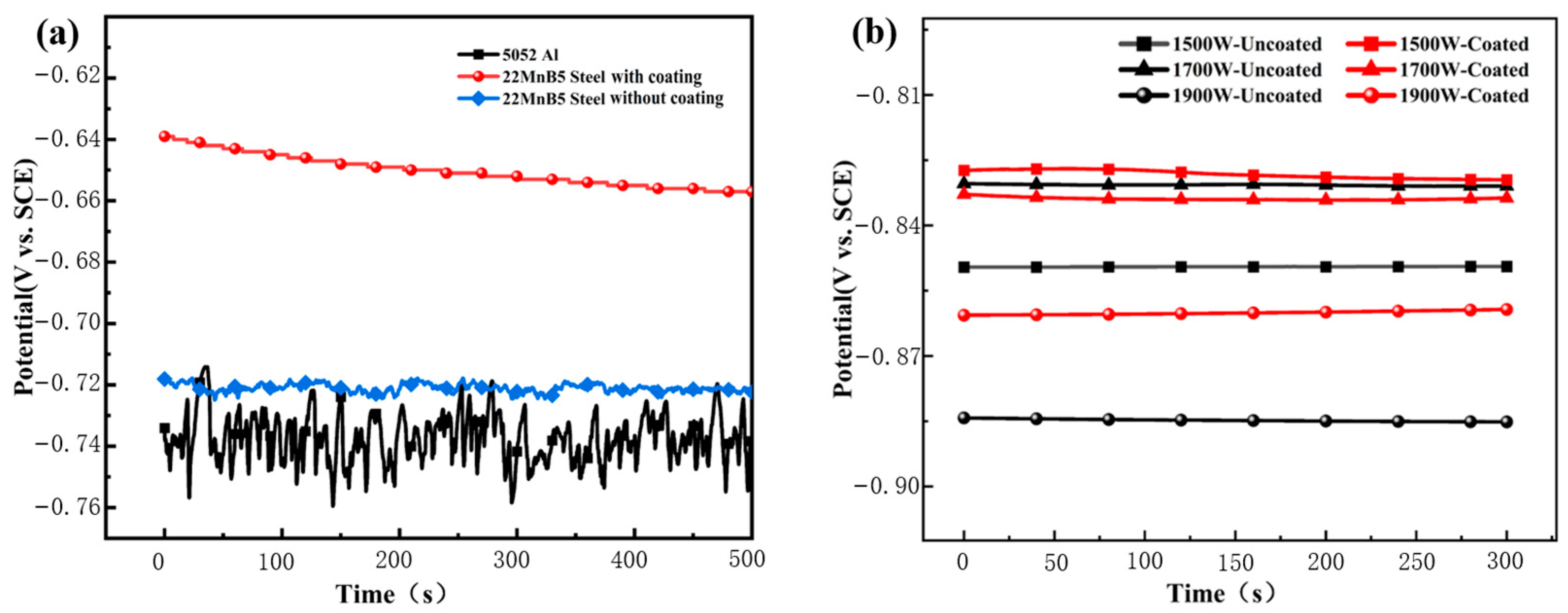
3.2.1. Open-Circuit Potential
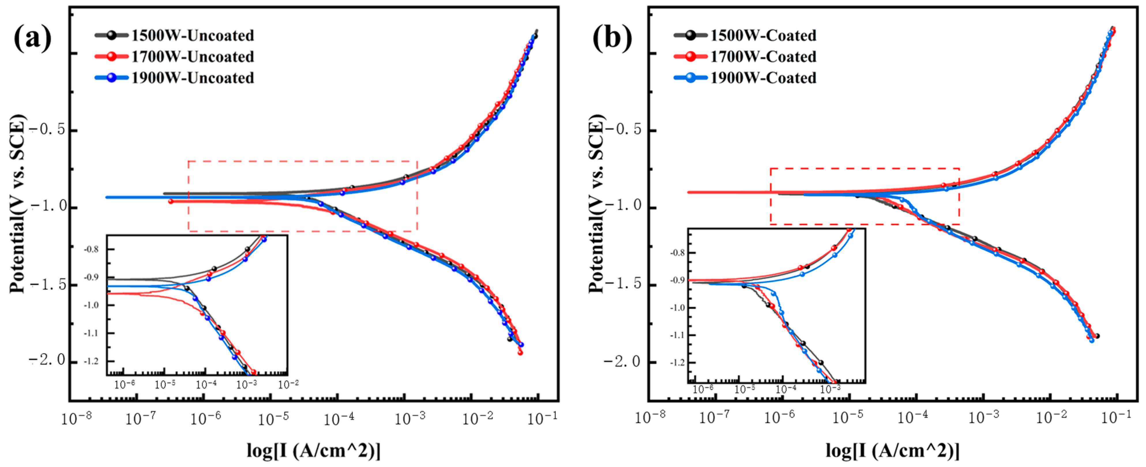
3.2.2. Dynamic Potential Polarization
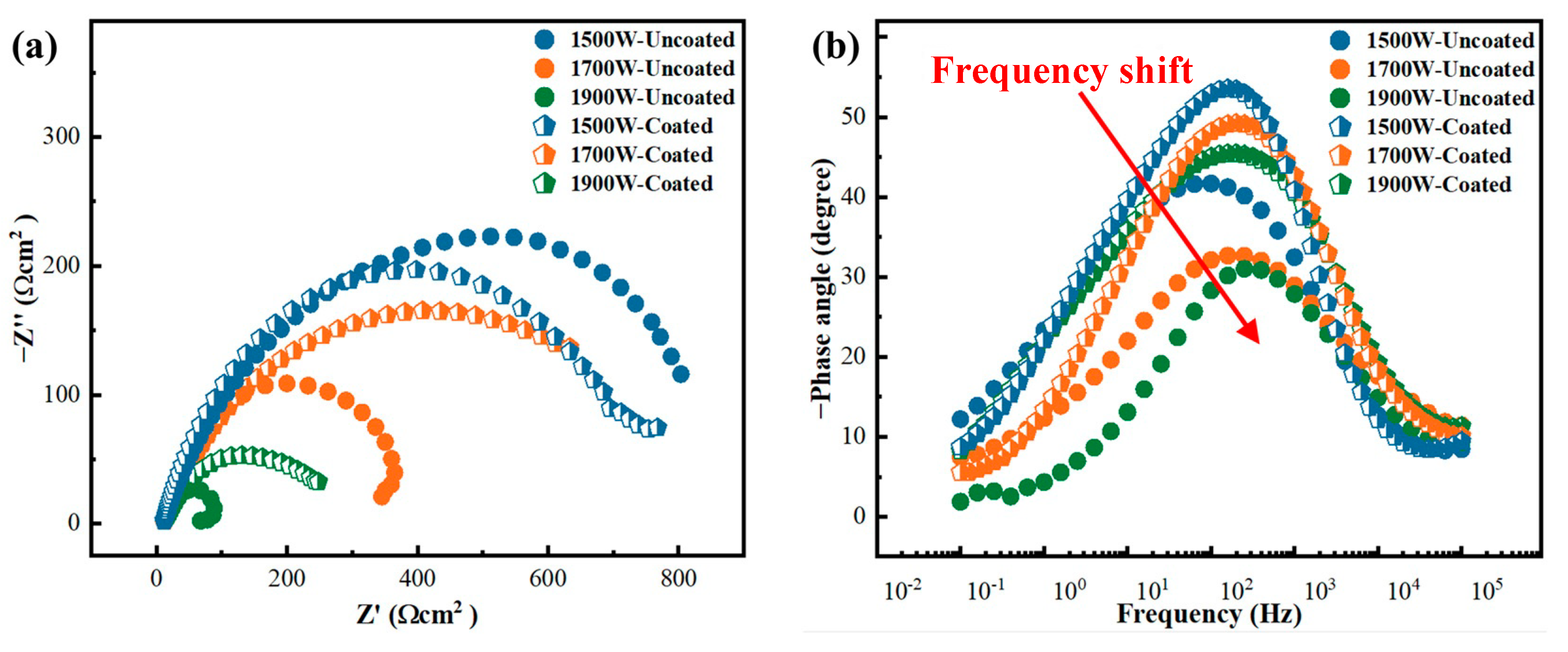
3.2.3. Electrochemical Impedance Spectroscopy
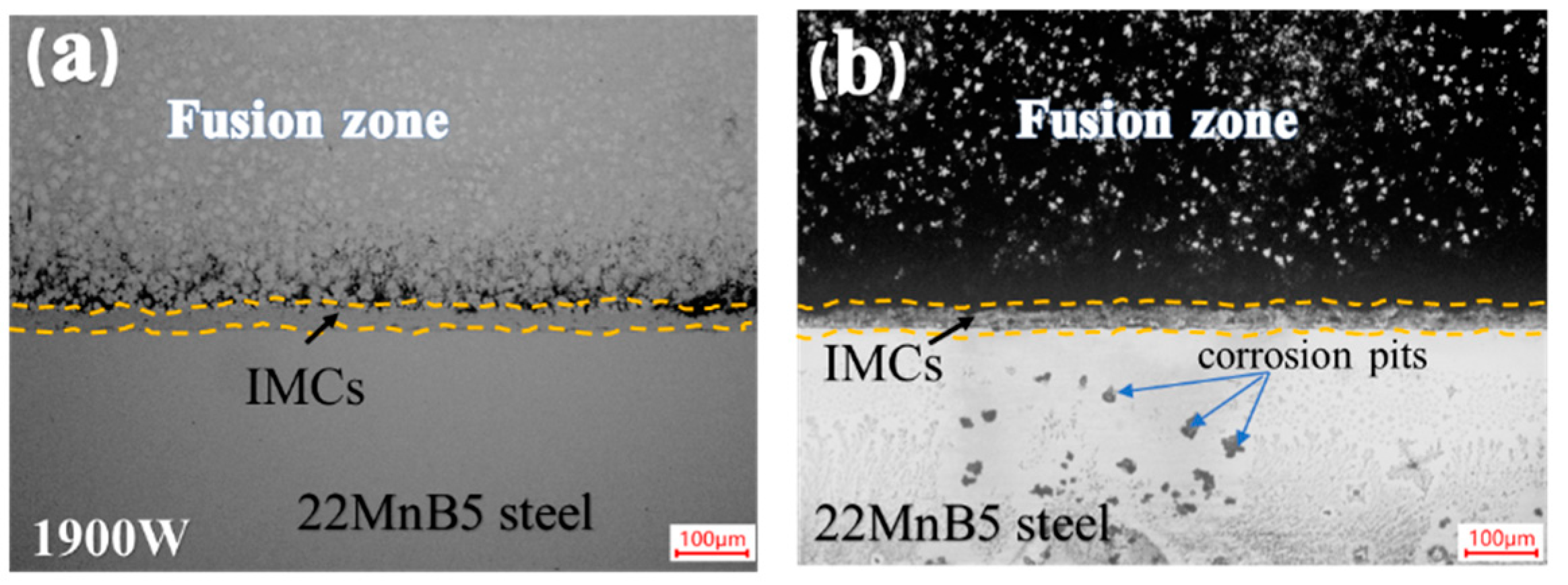
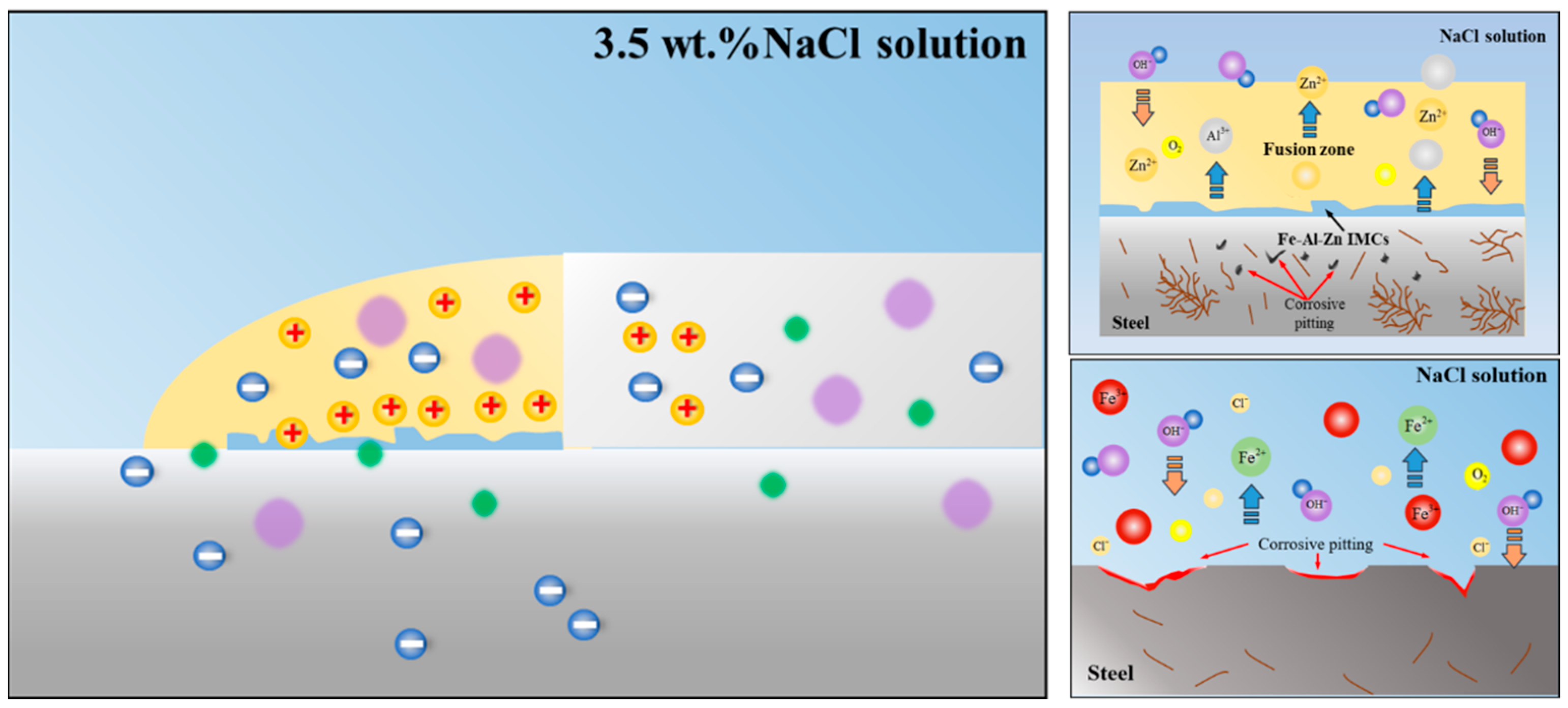
3.2.4. Corrosion Morphology and Mechanism of Welded Joint
4. Conclusions
Author Contributions
Funding
Data Availability Statement
Conflicts of Interest
References
- Kaushik, P.; Dwivedi, D.K. Al-steel dissimilar joining: Challenges and opportunities. Mater. Today 2022, 62, 6884–6899. [Google Scholar] [CrossRef]
- Pouranvari, M.; Abbasi, M. Dissimilar gas tungsten arc weld-brazing of Al/steel using Al-Si filler metal: Microstructure and strengthening mechanisms. J. Alloys Compd. 2018, 749, 121–127. [Google Scholar] [CrossRef]
- Torkamany, M.J.; Tahamtan, S.; Sabbaghzadeh, J. Dissimilar welding of carbon steel to 5754 aluminum alloy by Nd:YAG pulsed laser. Mater. Des. 2010, 31, 458–465. [Google Scholar] [CrossRef]
- Kumar Deepati, A.; Alhazmi, W.; Benjeer, I. Mechanical characterization of AA5083 aluminum alloy welded using resistance spot welding for the lightweight automobile body fabrication. Mater. Today 2021, 45, 5139–5148. [Google Scholar] [CrossRef]
- Zheng, M.; Yang, J.; Xu, J.Y.; Jiang, J.W.; Zhang, H.; Oliveira, J.P.; Lv, X.; Xue, J.; Li, Z. Interfacial microstructure and strengthening mechanism of dissimilar laser al/steel joint via a porous high entropy alloy coating. J. Mater. Res. Technol. 2023, 23, 3997–4011. [Google Scholar] [CrossRef]
- Yang, L.; Wan, Y.; Qin, Z.; Xu, Q.; Min, Y. Fabrication and corrosion resistance of a graphene-tin oxide composite film on aluminium alloy 6061. Corros. Sci. 2018, 130, 85–94. [Google Scholar] [CrossRef]
- Karbasian, H.; Tekkaya, A.E. A review on hot stamping. J. Mater. Process. Technol. 2010, 210, 2103–2118. [Google Scholar] [CrossRef]
- Kügler, H.; Vollertsen, F. Inductive preheating in laser beam welding of multimaterial joints of 22MnB5 and AA6016. Phys. Procedia 2013, 41, 41–48. [Google Scholar] [CrossRef]
- Kim, C.; Kang, M.J.; Park, Y.D. Laser welding of Al-Si coated hot stamping steel. Pro. Eng. 2011, 10, 2226–2231. [Google Scholar] [CrossRef]
- Maggi, S.; Murgia, M. Introduction to the metallurgic characteristics of advanced high-strength steels for automobile applications. Weld. Int. 2008, 22, 610–618. [Google Scholar] [CrossRef]
- Sun, Y.; Wu, L.; Tan, C.; Zhou, W.; Chen, B.; Song, X.; Zhao, H.; Feng, J. Influence of Al-Si coating on microstructure and mechanical properties of fiber laser welded 22MnB5 steel. Opt. Laser Technol. 2019, 116, 117–127. [Google Scholar] [CrossRef]
- Lin, W.; Li, F.; Wu, D.; Chen, X.; Hua, X.; Pan, H. Effect of Al-Si Coating on Weld Microstructure and Properties of 22MnB5 Steel Joints for Hot Stamping. J. Mater. Eng. Perform. 2018, 27, 1825–1836. [Google Scholar] [CrossRef]
- Ding, Y.; Shen, Z.; Gerlich, A.P. Refill friction stir spot welding of dissimilar aluminum alloy and AlSi coated steel. J. Manuf. Process. 2017, 30, 353–360. [Google Scholar] [CrossRef]
- Zhang, K.; Wu, L.; Tan, C.; Sun, Y.; Chen, B.; Song, X. Influence of Al-Si coating on resistance spot welding of Mg to 22MnB5 boron steel. J. Mater. Process. Technol. 2019, 271, 23–35. [Google Scholar] [CrossRef]
- Ma, H.; Qin, G.; Dang, Z.; Qu, S.; Chen, L.; Geng, P. Interfacial microstructure evolution and mechanical properties of inertia friction welded aluminium alloy/stainless steel joint with preheat treatment. Mater. Sci. Eng. A 2022, 836, 142671. [Google Scholar] [CrossRef]
- Khalaj, G.; Moradi, M.; Asadian, E. Exploring the impact of rolling temperature on interface microstructure and mechanical properties of steel–bronze explosive welded bilayer composite sheets. Weld. World 2023, 67, 1411–1425. [Google Scholar] [CrossRef]
- Ma, Y.; Dong, H.; Li, P.; Yang, J.; Wu, B.; Hao, X.; Xia, Y.; Qi, G. A novel corrosion transformation process in aluminum alloy/galvanized steel welded joint. Corros. Sci. 2022, 194, 109936. [Google Scholar] [CrossRef]
- Jiang, J.; Oliveira, J.P.; Yang, J.; Zheng, M.; Li, H.; Xu, W.; Wu, L.; Dou, T.; Wang, R.; Tan, C.; et al. Effect of defocusing distance on interfacial reaction and mechanical properties of dissimilar laser Al/steel joints with a porous high entropy alloy coating. Mater. Charact. 2024, 210, 113751. [Google Scholar] [CrossRef]
- Yang, J.; Oliveira, J.P.; Li, Y.; Tan, C.; Gao, C.; Zhao, Y.; Yu, Z. Laser techniques for dissimilar joining of aluminum alloys to steels: A critical review. J. Mater. Process. Technol. 2022, 301, 117443. [Google Scholar] [CrossRef]
- Windmann, M.; Röttger, A.; Kügler, H.; Theisen, W. Microstructure and mechanical properties of the heat-affected zone in laser-welded/brazed steel 22MnB5–AA6016 aluminum/AZ31 magnesium alloy. J. Mater. Process. Technol. 2017, 247, 11–18. [Google Scholar] [CrossRef]
- Narsimhachary, D.; Dutta, K.; Shariff, S.M.; Padmanabham, G.; Basu, A. Mechanical and microstructural characterization of laser weld-brazed AA6082-galvanized steel joint. J. Mater. Process. Technol. 2019, 263, 21–32. [Google Scholar] [CrossRef]
- Yang, J.; Xiao, M.; Wu, L.; Li, Z.; Liu, H.; Zhao, Y.; Guo, W.; Tan, C. The influence of laser power on microstructure and properties of laser welding-brazing of Al alloys to Al-Si coated 22MnB5 steel. Opt. Laser Technol. 2023, 162, 109318. [Google Scholar] [CrossRef]
- Cao, X.; Yi, Z.; Xu, C.; Luo, Z.; Duan, J.A. Study on laser/DP-MIG hybrid welding-brazing of aluminum to Al-Si coated boron steel. J. Manuf. Process. 2021, 64, 333–340. [Google Scholar] [CrossRef]
- Cheng, W.-J.; Wang, C.-J. Microstructural evolution of intermetallic layer in hot-dipped aluminide mild steel with silicon addition. Surf. Coat. Technol. 2011, 205, 4726–4731. [Google Scholar] [CrossRef]
- Windmann, M.; Röttger, A.; Kügler, H.; Theisen, W.; Vollertsen, F. Laser beam welding of aluminum to Al-base coated high-strength steel 22MnB5. J. Mater. Process. Technol. 2015, 217, 88–95. [Google Scholar] [CrossRef]
- Gao, K.; Gu, H.; Gong, J.; Li, K.; Dai, X.; Ye, K. Microstructure and mechanical properties of induction rolling welded joint for A283GRC steel and 5052 aluminum alloy. J. Mater. Process. Technol. 2023, 318, 118016. [Google Scholar] [CrossRef]
- Yu, G.; Chen, S.; Zhao, Z.; Wen, Z.; Huang, J.; Yang, J.; Chen, S. Comparative study of laser swelding-brazing of aluminum alloy to galvanized steel butted joints using five different filler wires. Opt. Laser Technol. 2022, 147, 107618. [Google Scholar] [CrossRef]
- Jia, L.; Shichun, J.; Yan, S.; Cong, N.; Genzhe, H. Effects of zinc on the laser welding of an aluminum alloy and galvanized steel. J. Mater. Process. Technol. 2015, 224, 49–59. [Google Scholar] [CrossRef]
- Ma, Y.; Dong, H.; Li, P.; Wu, B.; Huang, L.; Zhang, L.; Li, C.; Li, J. Galvanic corrosion of AA5052/304SS welded joint with Zn-based filler metal in marine engineering. Corros. Sci. 2023, 211, 110912. [Google Scholar] [CrossRef]
- Ma, Y.; Dong, H.; Li, P.; Wu, B.; Wu, W.; Qian, W.; Wang, B. Control of various Zn-based weld seam/steel interface structures in AA5083/FH36 steel welded joint. Mater. Des. 2023, 230, 111971. [Google Scholar] [CrossRef]
- El-Sayed, M.H.; Naka, M. Structure and properties of carbon steel–aluminium dissimilar joints. Sci. Technol. Weld. Join. 2013, 10, 27–31. [Google Scholar] [CrossRef]
- Song, J.L.; Lin, S.B.; Yang, C.L.; Fan, C.L. Effects of Si additions on intermetallic compound layer of aluminum–steel TIG welding–brazing joint. J. Alloys Compd. 2009, 488, 217–222. [Google Scholar] [CrossRef]
- Li, T.; Zhou, D.; Yan, Y.; Liu, J. Effect of beam oscillation on intermetallic compounds and mechanical properties of steel/aluminum laser welded joint. J. Manuf. Processes 2022, 73, 40–53. [Google Scholar] [CrossRef]
- Bertoncello, J.C.B.; Manhabosco, S.M.; Dick, L.F.P. Corrosion study of the friction stir lap joint of AA7050-T76511 on AA2024-T3 using the scanning vibrating electrode technique. Corros. Sci. 2015, 94, 359–367. [Google Scholar] [CrossRef]
- Wang, S.; Luo, K.; Sun, T.; Li, G.; Cui, J. Corrosion behavior and failure mechanism of electromagnetic pulse welded joints between galvanized steel and aluminum alloy sheets. J. Manuf. Process. 2021, 64, 937–947. [Google Scholar] [CrossRef]
- Shi, Y.; Li, J.; Zhang, G.; Huang, J.; Gu, Y. Corrosion Behavior of Aluminum-Steel Weld-Brazing Joint. J. Mater. Eng. Perform. 2016, 25, 1916–1923. [Google Scholar] [CrossRef]
- Volovitch, P.; Vu, T.N.; Allély, C.; Abdel Aal, A.; Ogle, K. Understanding corrosion via corrosion product characterization: II. Role of alloying elements in improving the corrosion resistance of Zn–Al–Mg coatings on steel. Corros. Sci. 2011, 53, 2437–2445. [Google Scholar] [CrossRef]
- Rajabalizadeh, Z.; Seifzadeh, D. Application of electroless Ni-P coating on magnesium alloy via CrO3/HF free titanate pretreatment. Appl. Surf. Sci. 2017, 422, 696–709. [Google Scholar] [CrossRef]
- Baek, J.S.; Kim, J.G.; Hur, D.H.; Kim, J.S. Anodic film properties determined by EIS and their relationship with caustic stress corrosion cracking of Alloy 600. Corros. Sci. 2003, 45, 983. [Google Scholar] [CrossRef]
- Martins, C.M.B.; Moreira, J.L.; Martins, J.I. Corrosion in water supply pipe stainless steel 304 and a supply line of helium in stainless steel 316. Eng. Fail. Anal. 2014, 39, 65–71. [Google Scholar] [CrossRef]
- Sravanthi, S.S.; Acharyya, S.G.; Joardar, J.; Chaitanya, V.N.S.K. A Study on Corrosion Resistance and Mechanical Performance of 6061 Aluminium Alloy: Galvanized Mild Steel Electron Beam Welds at Varying Welding Parameters. Trans. Indian Inst. Met. 2020, 73, 881–895. [Google Scholar] [CrossRef]
- Liu, W.; Li, M.C.; Luo, Q.; Fan, H.Q.; Zhang, J.Y. Influence of alloyed magnesium on the microstructure and long-term corrosion behavior of hot-dip Al–Zn–Si coating in NaCl solution. Corros. Sci. 2016, 104, 217–226. [Google Scholar] [CrossRef]


| Materials | Mg | Fe | Al | Cr | Cu | Zn | Mn | Si | C | B |
|---|---|---|---|---|---|---|---|---|---|---|
| 22MnB5 steel | - | Bal. | 0.05 | 0.20 | - | - | 1.18 | 0.25 | 0.2 | 0.005 |
| AA5052 Al | 2.2–2.8 | 0.4 | Bal. | 0.2 | 0.1 | 0.1 | 0.1 | 0.25 | - | - |
| Zn-Al22 | - | - | 22 | - | 0.8 | Bal. | - | - | - | - |
| Laser Power /W | Welding Speed /m∙min−1 | Wired Feed Speed /m∙min−1 | Defocused Amount /mm | Shielding Gas Flow /L∙min−1 |
|---|---|---|---|---|
| 1500 | 0.3 | 1.9 | +35 | 15 |
| 1700 | ||||
| 1900 |
| Points | Elements (at. %) | Possible Phases | |||
|---|---|---|---|---|---|
| Al | Fe | Zn | Si | ||
| 1 | 48.89 | 0.82 | 50.11 | 0.18 | Fe2Al5−xZnx |
| 2 | 70.24 | 23.10 | 6.42 | 0.24 | Fe2Al5−xZnx |
| 3 | 57.41 | 11.46 | 31.04 | 0.09 | Fe2Al5−xZnx + FeZn10 |
| 4 | 70.6 | 19.58 | 9.62 | 0.21 | Fe2Al5−xZnx |
| 5 | 68.75 | 17.00 | 1.95 | 12.30 | Fe2Al7Si |
| 6 | 54.81 | 16.26 | 26.01 | 2.92 | Fe2Al5−xZnx + FeZn10 |
| 7 | 63.67 | 19.94 | 10.48 | 5.92 | Fe2Al5−xZnx |
| 8 | 67.92 | 20.68 | 7.23 | 4.16 | Fe2Al5−xZnx |
| 9 | 16.01 | 11.74 | 71.89 | 0.35 | Fe2Al5−xZnx + FeZn10 |
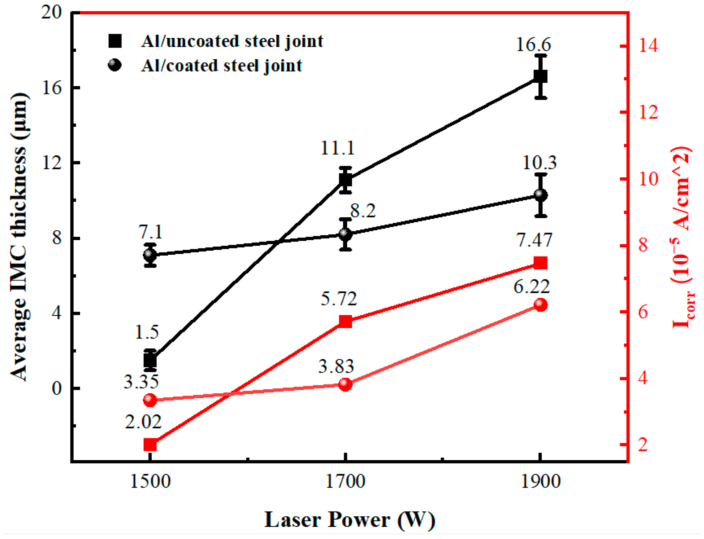
| Cases | 1500 W | 1700 W | 1900 W |
|---|---|---|---|
| Al/Al-Si coated steel joints | 7.1 | 8.2 | 10.3 |
| Al/uncoated steel joints | 1.5 | 11.1 | 16.6 |
| Laser Power (W) | Corrosion Current Density (10−5 A/cm2) | Corrosion Potential (V) | ||
|---|---|---|---|---|
| Uncoated Steel | Coated Steel | Uncoated Steel | Coated Steel | |
| 1500 W | 2.0235 | 3.3538 | −0.945 | −0.9683 |
| 1700 W | 5.7234 | 3.8333 | −0.9512 | −0.952 |
| 1900 W | 7.4773 | 6.2223 | −0.9637 | −0.9854 |
Disclaimer/Publisher’s Note: The statements, opinions and data contained in all publications are solely those of the individual author(s) and contributor(s) and not of MDPI and/or the editor(s). MDPI and/or the editor(s) disclaim responsibility for any injury to people or property resulting from any ideas, methods, instructions or products referred to in the content. |
© 2024 by the authors. Licensee MDPI, Basel, Switzerland. This article is an open access article distributed under the terms and conditions of the Creative Commons Attribution (CC BY) license (https://creativecommons.org/licenses/by/4.0/).
Share and Cite
Wu, L.; Oliveira, J.P.; Yang, J.; Xiao, M.; Zheng, M.; Xu, W.; Zhao, Y.; Wang, F.; Zhang, H. Effect of Al-Si Coating on the Interfacial Microstructure and Corrosion Resistance of Dissimilar Laser Al Alloy/22MnB5 Steel Joints. Metals 2024, 14, 328. https://doi.org/10.3390/met14030328
Wu L, Oliveira JP, Yang J, Xiao M, Zheng M, Xu W, Zhao Y, Wang F, Zhang H. Effect of Al-Si Coating on the Interfacial Microstructure and Corrosion Resistance of Dissimilar Laser Al Alloy/22MnB5 Steel Joints. Metals. 2024; 14(3):328. https://doi.org/10.3390/met14030328
Chicago/Turabian StyleWu, Lingqing, Joao Pedro Oliveira, Jin Yang, Ming Xiao, Min Zheng, Wenhu Xu, Yixuan Zhao, Feifan Wang, and Hua Zhang. 2024. "Effect of Al-Si Coating on the Interfacial Microstructure and Corrosion Resistance of Dissimilar Laser Al Alloy/22MnB5 Steel Joints" Metals 14, no. 3: 328. https://doi.org/10.3390/met14030328