Article

Steel Sheet Deformation in Clinch-Riveting Joining Process

1
Faculty of Mechanical Engineering and Aeronautics, Rzeszow University of Technology, Al. Powstancow Warszawy 8, 35-959 Rzeszow, Poland
2
Doctoral School of the Rzeszów University of Technology, Al. Powstancow Warszawy 12, 35-959 Rzeszow, Poland
*
Author to whom correspondence should be addressed.
Metals 2024, 14(3), 367; https://doi.org/10.3390/met14030367
Submission received: 20 February 2024 / Revised: 15 March 2024 / Accepted: 19 March 2024 / Published: 21 March 2024
(This article belongs to the Special Issue New Technology of Welding/Joining of Metallic Materials)

Abstract

:
This paper presents the deformation of a joined sheet after the clinch riveting process. The DX51D steel sheet with zinc coating was used. The samples to be joined with clinch riveting technology had a thickness of 1 ± 0.05 mm and 1.5 ± 0.1 mm. The sheet deformation was measured before and after the joining process. The rivet was pressed in the sheets with the same dimension between the rivet axis and three sheet edges: 20, 30, and 40 mm. For fixed segments of the die, from the rivet side close to the rivet, the sheet deformation was greater than that of the area with movable segments. The movement of the die’s sliding element caused more sheet material to flow in the space between the fixed part of the die and movable segments. Hence, the sheet deformation in these places was smaller than for the die’s fixed element—the sheet material was less compressed. For sheet thickness values of 1.5 mm and a width value of 20 mm, the bulk of the sheet was observed. For a sheet width of 20 mm, it was observed that the deformation of the upper and lower sheets in the area of the rivet was greater than for sheet width values of 30 or 40 mm.

1. Introduction

Manufacturing elements with a specific geometric quality is still a challenge. Despite the improvement in the designing of machines and machine tools, plastically formed elements sometimes show unpredictable shape changes during the manufacturing or joining process. The technological parameters of the plastic forming processes influence the deformations and dimensional accuracy of the manufactured elements. Cold- and hot-formed thin-walled metal and plastic elements require different control techniques [1,2]. Geometric variability occurs when the thermal energy necessary to form the joint is supplied locally [3]. As a result of progress, including the introduction of new assembly technologies, there is a need to develop the control and assessment of the shape and dimension quality of products. In addition to the technological parameters of the assembly process, the location of the joint in a thin-walled structure is very important. Designers of thin-walled structures often have limitations on the locations of joints. The shorter the distance from the edge of the sheet is, the smaller the width of the material band needed to form the joint is. Less material means less additional weight in the thin-walled structure. The close location of the joint to the edges of the connected layers (or one of them) causes large deformations (Figure 1).
During the assembly processes of thin-walled elements, there is a varying intensity of interference in the material structure of the joined elements. Each thin-walled element processing and assembly technology causes shape deformations and changes in the dimensions of the designed element [4,5]. Deformations resulting from springing in the joint area are also very important [6,7]. As a result of joining the sheets, local action on the material may cause them to spread apart (Figure 2). When joining thin-walled elements, it is important that such deformations are very small. Their complete elimination is difficult and requires a series of tests to determine the parameters of the joining process.
Automotive manufacturers are increasingly using pressed-joining technologies. This group of connecting technologies includes, among others, self-piercing riveting (“SPR”) [8,9,10,11], clinching (“CL”) [12,13,14,15,16,17], solid self-piercing riveting (“SSPR”) [18,19,20,21,22,23], and clinch riveting (“CR”) [24,25,26,27,28,29]. Companies see more and more potential for this group of pressed joints. It is often necessary to connect more than two layers of material; this is possible due to technology, for example, “SPR” [30,31,32]. In the case of clinching joints, it is also possible to make a three-layer joint for certain material arrangements [33]. Each joining technique has its limitations and dedicated applications. The types of materials, their thicknesses, the arrangements of tools and material layers, and the amounts of forming force are very important. When pressed joints are formed, including clinching, especially in the case of high-strength materials, significant tool loads occur [34]. The use of the above-mentioned joining methods in the case of metallic materials does not require drilling a hole before joining. It is possible to combine composites with metallic materials, with certain limitations. When a composite is the upper layer and a metal is the lower layer, for some arrangements, “SPR” [35,36,37,38], clinching [39,40,41,42,43], or solid self-piercing riveting [39,44] joints can be formed. There are an increasing number of industrial applications that involve the joining of composite elements using the above-mentioned pressure joining techniques [41,45]. The joining of a composite and a metal using a punching rivet and heating to 180 °C was presented, for example, in [46]. If the lower layer is less plastic and the upper layer is more plastic, it is possible to connect them through clinching, where a hole is made in the lower layer for two sheets [47] or even three sheets [48]. The reverse combination of the material arrangement, i.e., where the upper layer is composite and the lower one is metal, when a hole is made, is possible in order to create a joint. However, composite fibers are subject to significant deformation [49]. If the lower layer is a composite and the upper layer is a metal, it is possible to join them through clinching, but this requires the heating of the joined materials [50]. However, heating the materials causes additional subsequent return deformations, which affect the deformation of the shape and dimensions of the joined elements.
Each method of joining thin-walled elements causes, to a greater or lesser extent, deformations of the material near the joint axis. The deformation of the top sheet in the joint axis area depends on the type of die used to forming the clinching joints [51]. The distance between the parts of the clinch joint influences the interlock parameters and joint strength. For the single-strap butt joint, the distance between two joints has a negligible effect on the shearing effect [52]. For solid punch riveting technology, the influence of the number of joints on the deformation of sheet metal surfaces was presented in [23]. The gap between the sheets in that study depended on the construction of the die. The sheet deformation in the joint axis for the stir-friction welding process was presented in [53]. For self-piercing riveting, the deformation around the joint axis and the total deformation of an aluminum door’s inner sub-assembly was analyzed in [54,55]. From the point of view of the tightness of the connection, it is important that the sheets do not bend around each other and that the corrosion factor does not penetrate the joint between the joined sheets. Research [56,57] has shown that both electrochemical and galvanic corrosion reduce the load bearing capacity of the clinch joint.
This publication presents the influence of using different values of the width of the joined sheet samples and the distance of the joint axis from the external edges of the sheets on the amount of deformation of the joined elements. The joints were made using clinch riveting technology. Tests were carried out to join two sheets of thicknesses of 1.0 mm and 1.5 mm that were made of DX51D steel. The joints were experimentally formed and the influences of the distance of the joint from the lap joint on the forming force and the amount of deformation of the joined elements near the joint were analyzed. The joining technology was clinch riveting with a solid deformable rivet. The analysis showed that the deformations of the sheet appeared not only in the joint area but also in the edge of the sheet for different sheet width and thickness values. The geometry of the die caused different deformations of the sheet in specific planes of the joint.

2. Experimental Measurements

2.1. Sheet Material

Steel sheets are commonly used in light gauge profiles and thin-walled structures. Experimental tests of the sheet deformation were conducted for the DX51D steel sheet (material number 1.0226, according to the EN 10327:2004 standard [58]) with ZiNc coating. The samples for joining through clinch riveting technology had thickness values of 1 ± 0.05 mm and 1.5 ± 0.1 mm. Grammage of the zinc layer was 275 g/m2 with thickness of about 20 µm. Basic mechanical properties are presented in Table 1 (average values), and the chemical compositions are shown in Table 2 (maximum content).

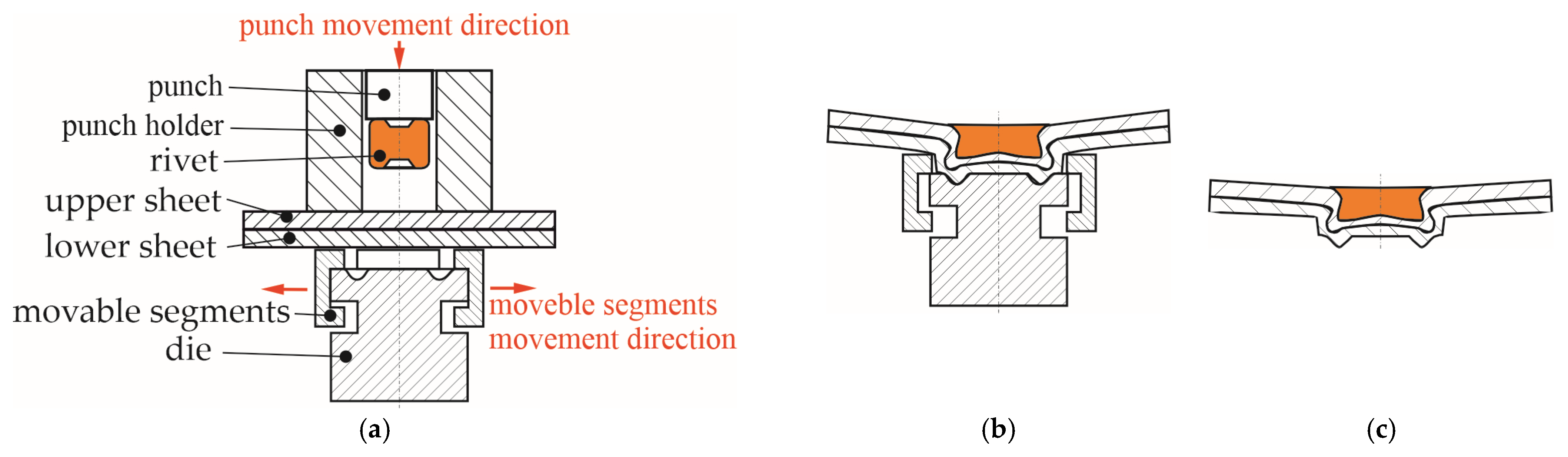
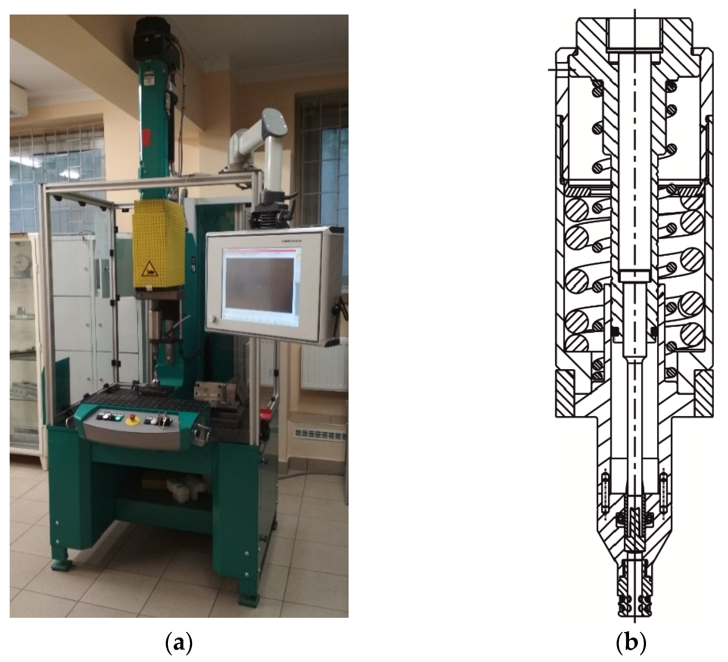
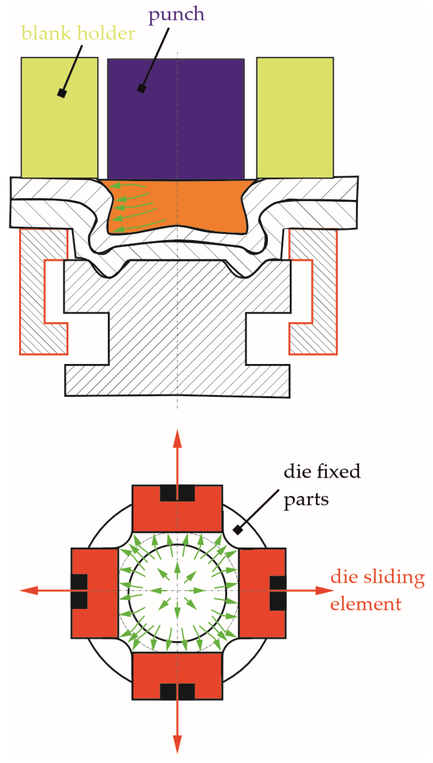
2.2. Clinch-Riveting Joining Process

Clinch-riveted joints were prepared in the Pressed Joint Laboratory of the Machine Design Department at Rzeszow University of Technology (Rzeszow, Poland). The TOX Pressotechnik machine (Figure 3) was used to prepare joint samples. Maximum joining force generated by EMPK electric drive system (Tox Pressotechnik, Wroclaw, Poland) is 100 kN. The die is fixed to the C-frame body. The punch system, driven by EMPK system, is moved along vertical axis. The accuracy of the punch system displacement is 0.01 mm. The strain gauge system is measuring the forming force with an accuracy of up to 0.5%.
For preparing clinch-riveted joints, the “SKB” die, with movable segments, was used, and punch system, with rivet feeder, and “TOX Pressotechnik” steel rivets were used. The die has four fixed parts and four movable segments. The geometry and main dimensions of the die are presented in Figure 4a. The punch system consists of punch, blank holder with spring, and rivet feeder system. The geometry and main dimensions of the punch and blank holder are presented in Figure 4b. The deformable steel rivets (type A5x5-2Al), manufactured by “TOX Pressotechnik”, had a hardness of 400HV1 (average values from 5 measurements). Hardness measurement, using the Vickers method, was performed using a Matsuzawa microhardness tester (type Micro-Sa, Seiki Co., Ltd.) (Nagaoka-shi, Japan). The measurement load was 10 N (in accordance with the ISO 6507-1:2018 standard [59]). The characteristics of the rivets have been presented in other papers [25,28].
The geometry and dimensions of used rivets are presented in Figure 4c. An example of the forming-force–displacement diagram from clinch riveting process is presented in Figure 5. The maximum punch movement along vertical axis was set up to obtain the same level of the top surface of the rivet and the top surface of upper sheet.
In the clinch riveting process, seven phases can be observed:
-
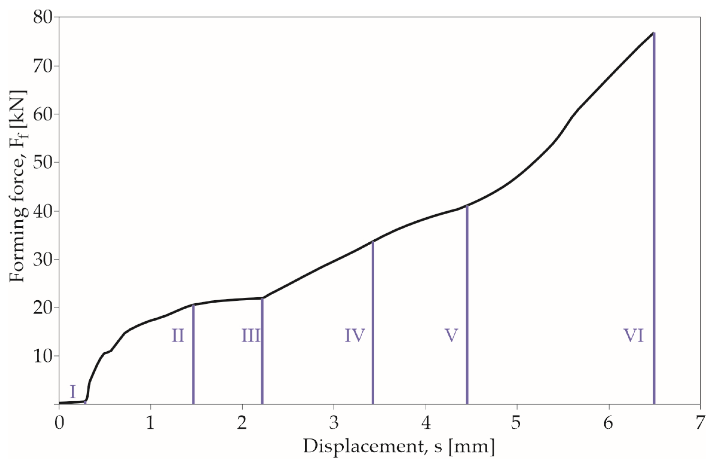
Phase I—special rivet feeder with an automatic rivet insertion mechanism positions the rivet by the movement of the holder springs (at two levels);
-
Phase II—rivet contacts the upper sheet;
-
Phase III—rivet is pressed with sheets into the die groove;
-
Phase IV—the lower surface of the lower sheet touches the bottom surface of the die;
-
Phase V—the rivet material fills the free space formed after the movement of the sheet material in the die cavity and space formed after displacement of the die’s movable segments;
-
Phase VI—the rivet material flows intensively in its lower part in the transverse direction—the joint interlock is formed;
-
Phase VII—the punch system moves to basic point.
In Figure 5, only phases from 2 to 6 are presented. Phases 1 and 7 are not closely related to the formation of the joint—they are preparatory-completion movements. So, the force and displacement values at this movement phase (phase 7) were not recorded.

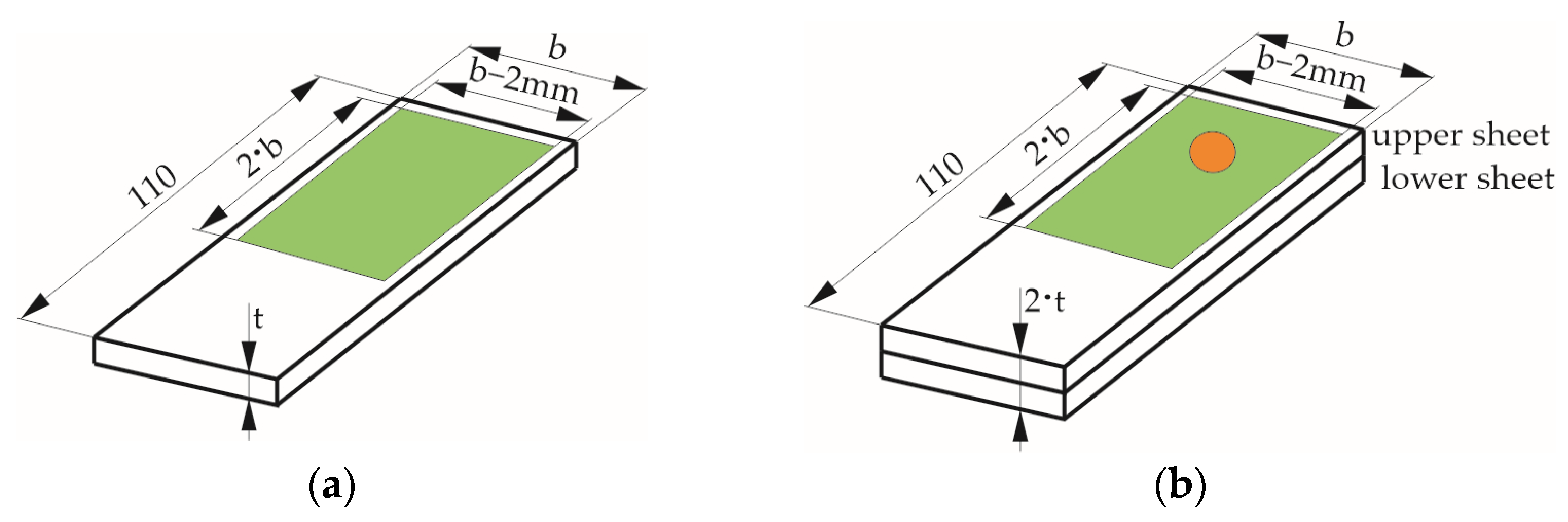
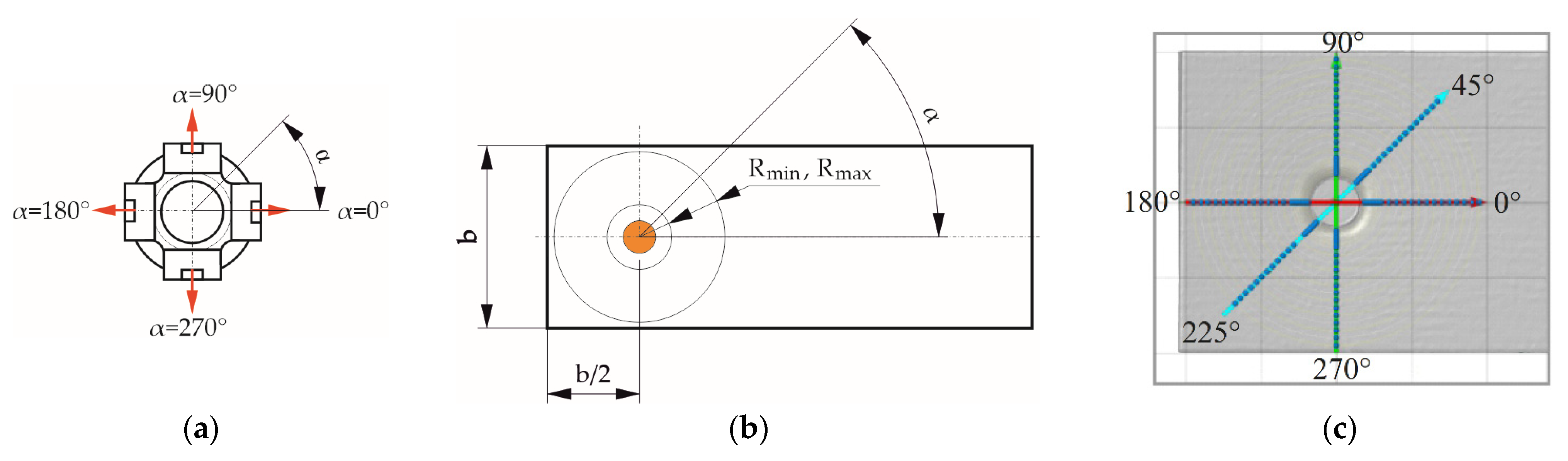
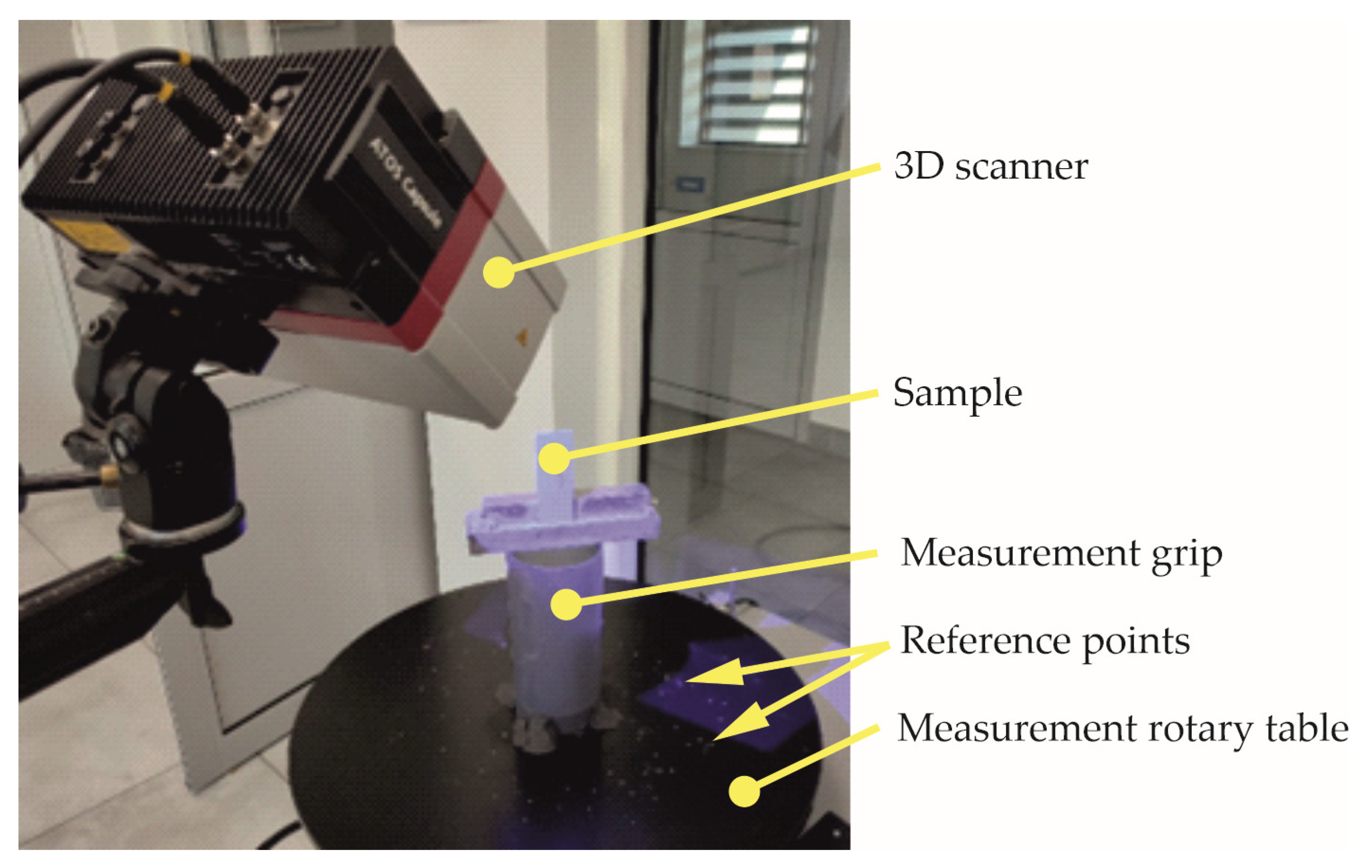
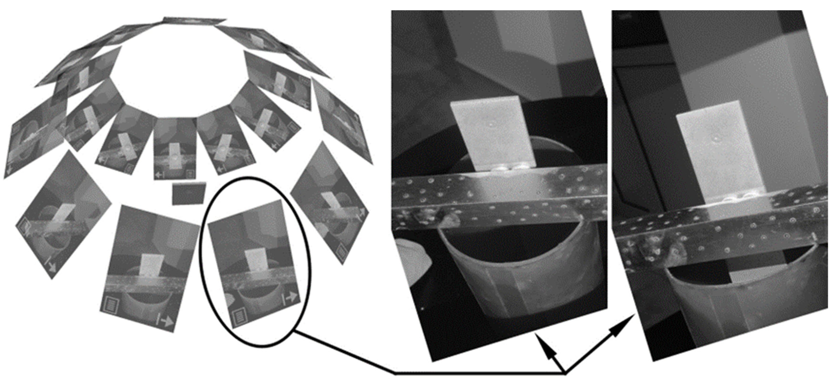
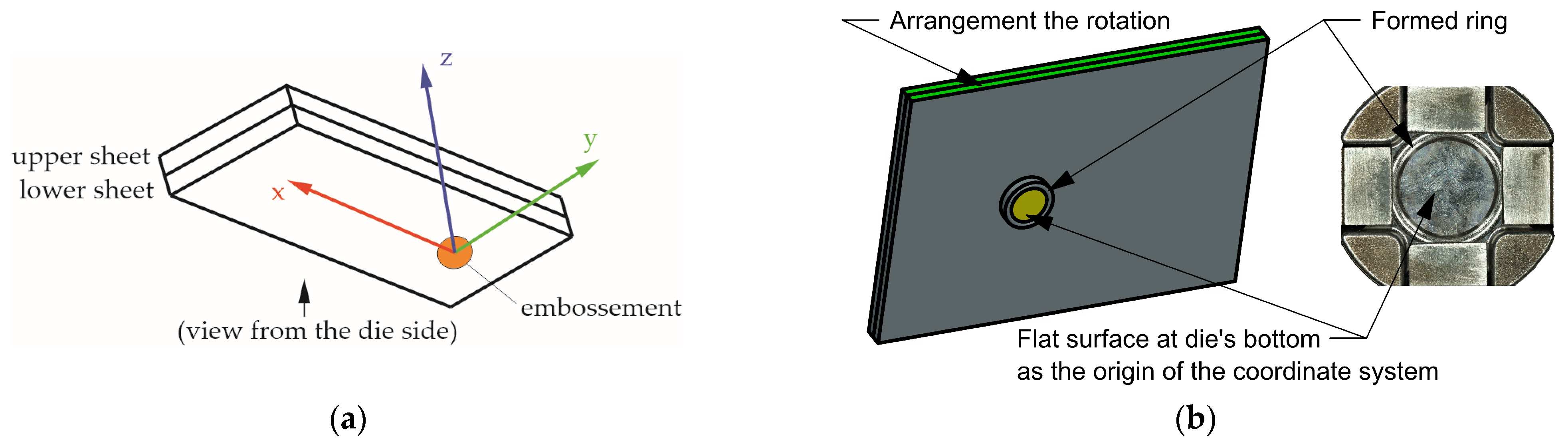
2.3. Sheet Deformation Measurements

All samples were cut out from sheets with dimensions of 2500 mm × 1250 mm × 1.0 mm and 2500 mm × 1250 mm × 1.5 mm. The sheet sample deformation was measured before (Figure 6a) and after (Figure 6b) joining process. The rivet was pressed in the sheet while ensuring the same dimensions (b) between rivet axis and three sheet edges (sheet width divided by two)—see Figure 7b. The measurements of the sheet deformation were made for two sheet thickness values (1 and 1.5 mm) of clinch-rivet joints and for three values of the sheet width (b = 20, 30 and 40 mm). In Figure 7, the scheme of the measurement-point coordinates for chosen angles (0°, 45°, 90°, 180°, and 270°) is presented.
The measurement radius was changed from Rmin to Rmax. The radius of measurement points was chosen from Rmin = 3.75 mm to dimensions equal to Rmax = (b − 2 mm)/2 depending on the sheet width. The minimum and maximum dimensions of the measurement radius for all sheet widths are presented in Table 3.
The apparatus used in measurement of sheet deformation was ATOS Capsule 200 MV200 (Carl Zeiss Sp. z o.o., Warsaw, Poland)—see Figure 8. The measurement system was chosen while ensuring the measurement parameters, according to VDI/VDE 2634 Part 3 standard [60], were in line with the GOM Acceptance Test. The maximum deviations after acceptance test, for used 3D scanner, were as follows: probing error form—0.001 mm, probing error—0.003 mm, sphere spacing error—0.008 mm, and length measurement error—0.009 mm. Additionally, after every five measurements, to ensure high-quality results, the scanner was calibrated. The references points used to generate the mesh model were placed on the measurement table and measurement grip.
To generate the measurement mesh, two measurement series were made, each with 10 pictures, using automatic work with a rotary table. Each of the shots consisted of two photos, recorded using the cameras, of the measurement plate—see Figure 9. The transformation of individual shots took place through common reference points.
It was assumed that the sheet-surface deformation comparison would be made on samples with a common coordinate system adopted in accordance with Figure 10a. The bottom of the die was taken as the main reference plane (Z = 0.00). This plane was determined through the “Fitting Plane” method in GOM Inspect program. The origin for the X and Y axes was determined from the torus (as result from the cross-section of the plane parallel to the Z plane and the formed ring). The rotation of XYZ coordinate system was set as parallel to the side surface of the sheet samples—see Figure 10b.

3. Results and Discussion

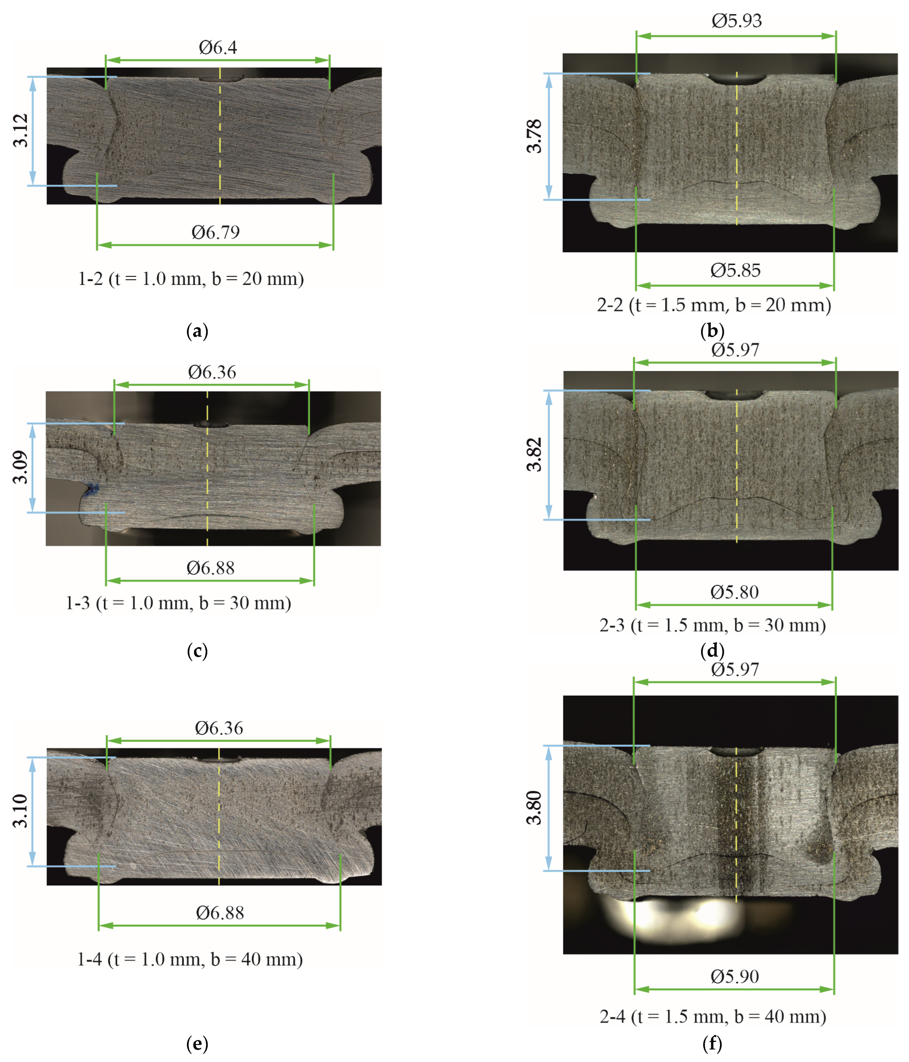
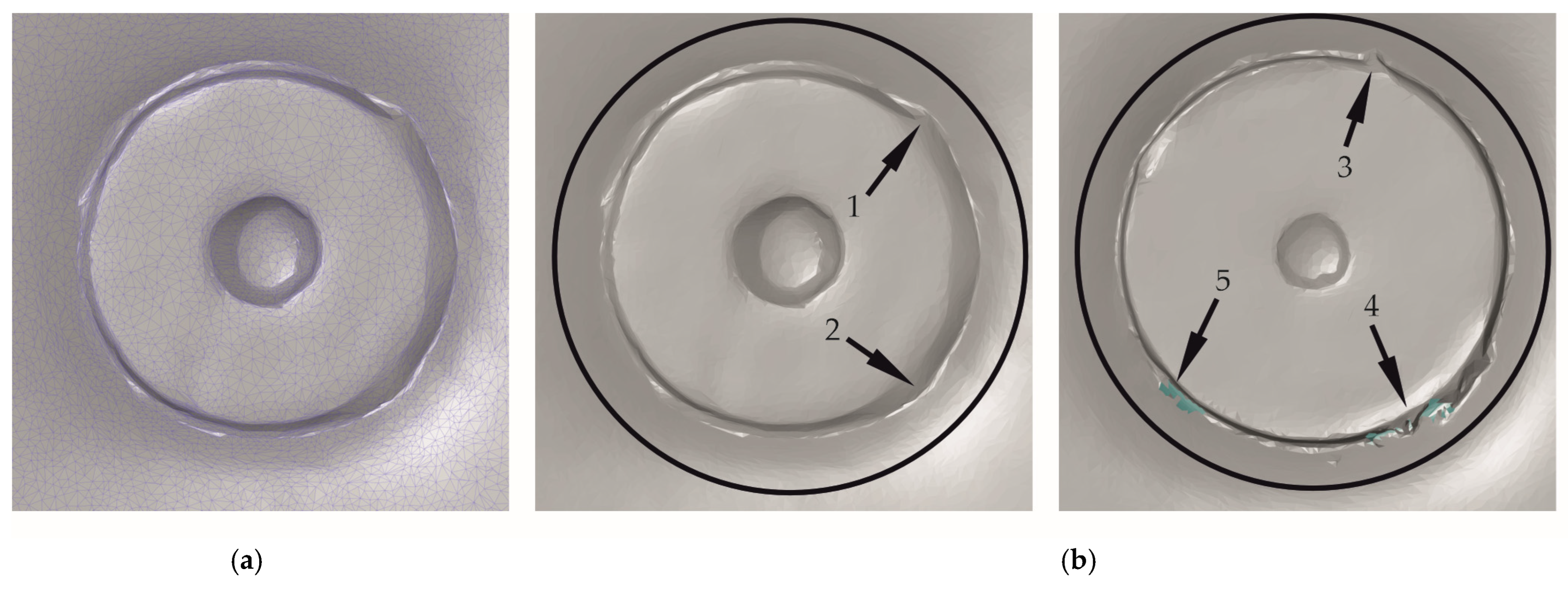
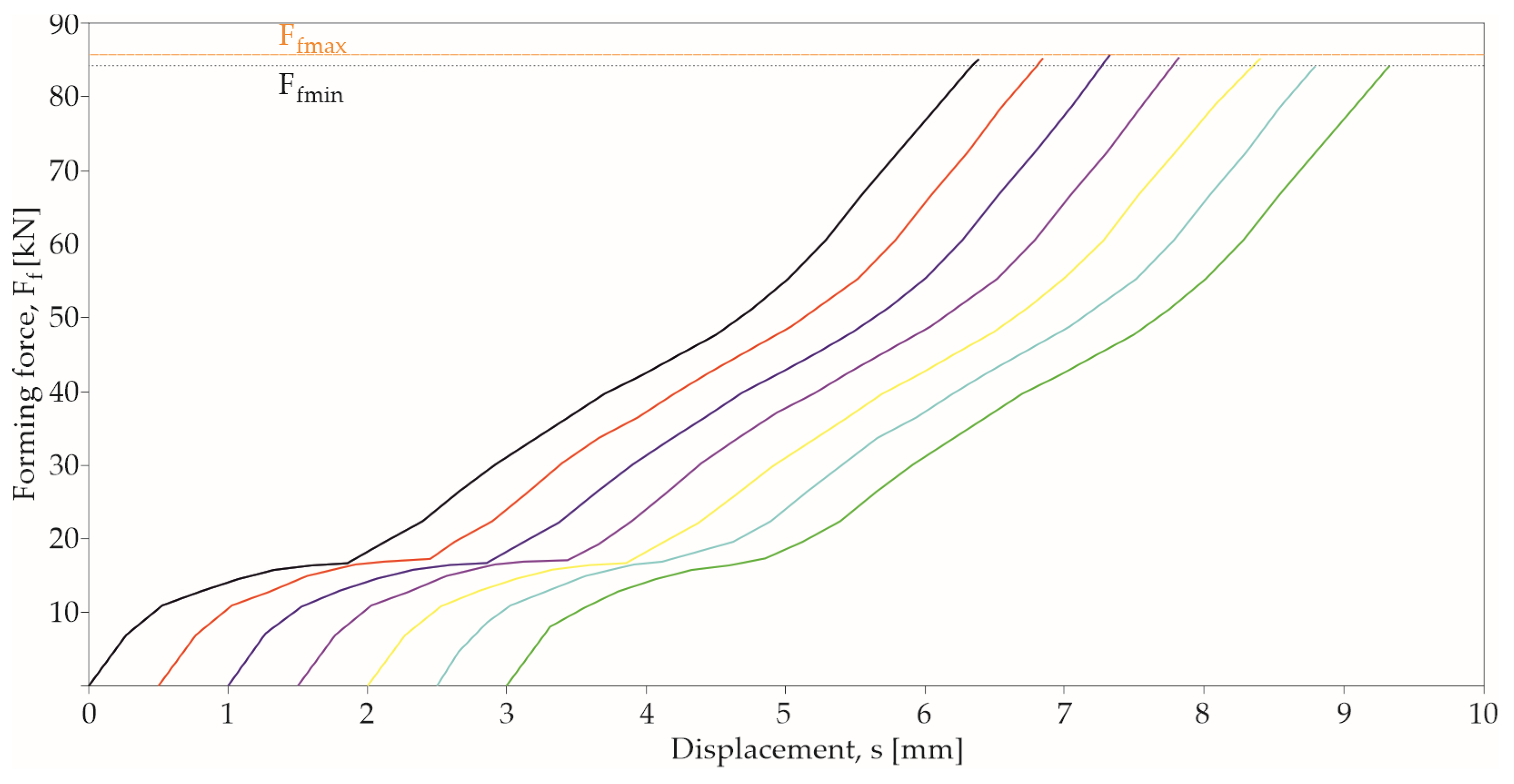
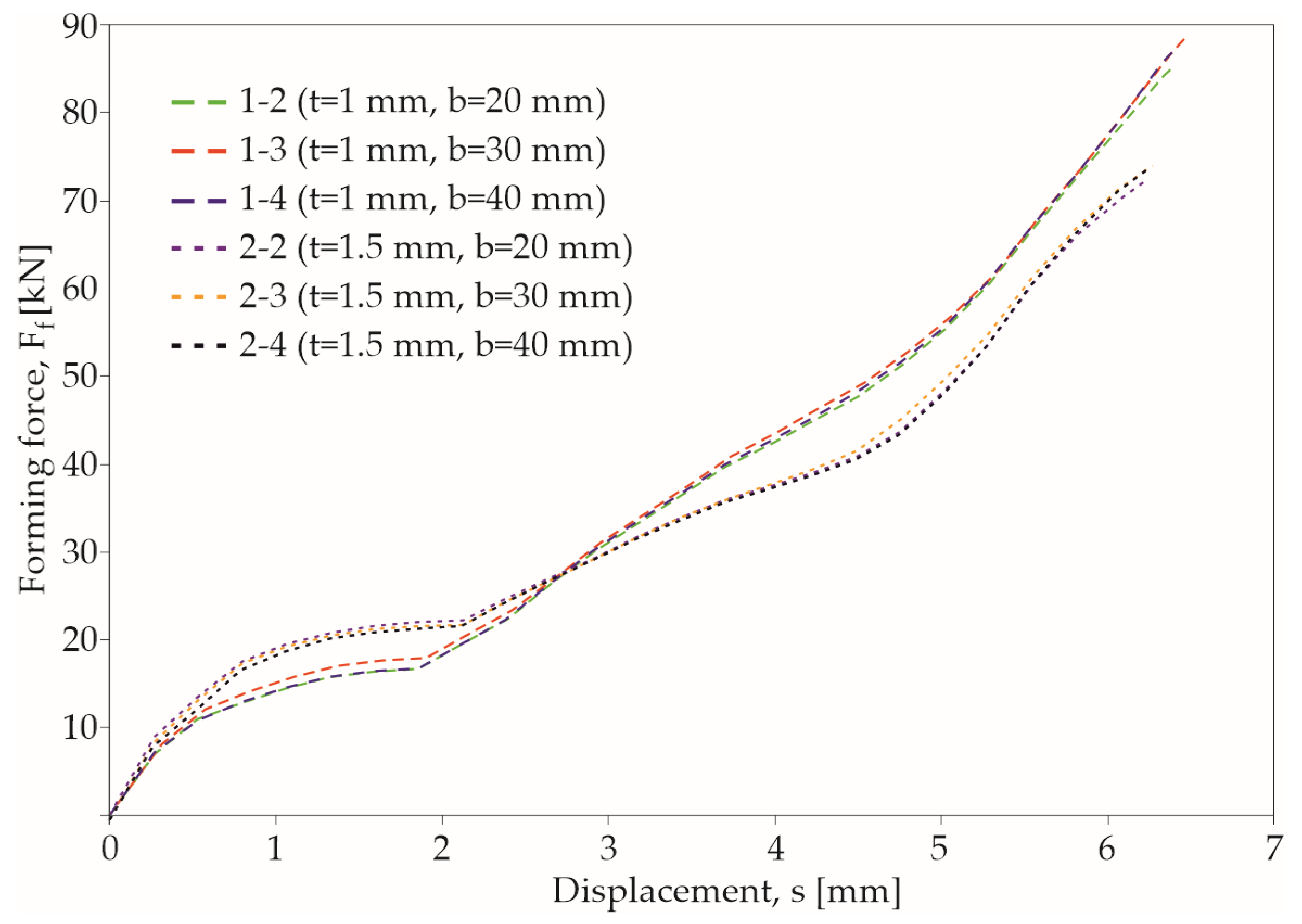
3.1. Forming Process of the Clinch-Rivet Joint

During the clinch riveting process, the forming force was measured and recorded for each joint combination seven times—see Figure 11. For determining the mean values ( x n ¯ ), standard deviation ( s ), and coefficient of variation ( c v ), five recorded values were taken into account. The calculated parameters (Equations (1)–(4)) are presented in Table 4. For each sheet thickness and width, forming-force–displacement diagrams are presented in Figure 12.
x n ¯ = i = 1 n x i n
s = 1 n 1 · i = 1 n x i x n ¯ 2
c v = s x n ¯ · 100 %
Here,
x n ¯ —mean values of forming force (kN);
x i —simple values of forming force (kN);
n —number of measurements;
s —standard deviation (kN);
c v —coefficient of variation (%).
E f = s = 0 s F m a x F f · d s
Here,
E f —forming energy (J);
s —displacement (mm);
s F m a x —displacement for maximum forming force (mm);
F f —forming force (kN).
The thickness of the layers and the width of the samples had an influence on the forming force and its course (Figure 12). In the case of assembly of thin-walled structures, access, for forming tools, to the joining position is often limited. Then, the place where the material layers are joined may be close to the edge (Figure 1a). In this case, the formed material has less resistance to movement. This results in a lower forming force and different material flow conditions.
The same die was used for the joining of sheets of 1 and 1.5 mm thickness. The volume and shape of the die cavity for both cases resulted in the obtainment of different joint interlocks—see Figure 13. To ensure that the surfaces of the rivet and the sheets are at the same level after the joining operation, the rivet must be pressed deeper for sheets with a thickness of 1 mm. This increases its maximum diameter in the joint by approximately 15% in relation to the maximum diameter of the rivet in joints of 1 mm thick sheets. The high part of the rivet in the joint was lower by about 17% for a sheet with a thickness of 1 mm according to a sheet with a thickness of 1.5 mm. Therefore, the forming force and energy consumption are higher for sheets with a thickness of 1 mm.
Changing the distance of the joint from the sheet edge from 20 mm to 10 mm caused the sheet material to flow more freely in the radial direction outside the die, which resulted in the lowering the force necessary to form the joint by 2.95% for sheets with a thickness of 1 mm and by 2.65% for sheets with a thickness of 1.5mm.
By reducing the distance of the joint from the edge of the sheet, the forming force and, consequently, the demand for forming energy can be reduced. Another way to reduce the energy absorption of the joint formation process is to use a rivet of a different hardness [28], use a tubular rivet [25], or change the insertion depth of the rivet [61].

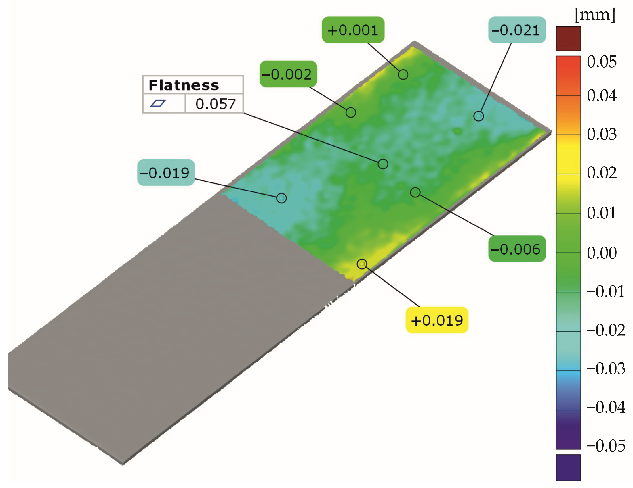
3.2. Sheet Deformation Measurement before Joining Process

In order to properly interpret the results of the changes in surface deformation near the places where the sheets were joined, it was decided to determine the flatness errors of the sheets before joining. To ensure that there was sheet deformation before joining (for example, deformation from the sample cutting process), all sheet samples were scanned with the ATOS Capsule scanner. Examples of sheet area scans are presented in Figure 14. Average sheet thickness and sheet width values are given in Table 5. For each sheet strip, the measured dimensions were at an acceptable level.
All samples were laser-cut from the same sheet metal. Measurements of the sheet metal strips before joining showed that the actual dimensions of the samples were consistent with the dimensional parameters provided by the manufacturer.

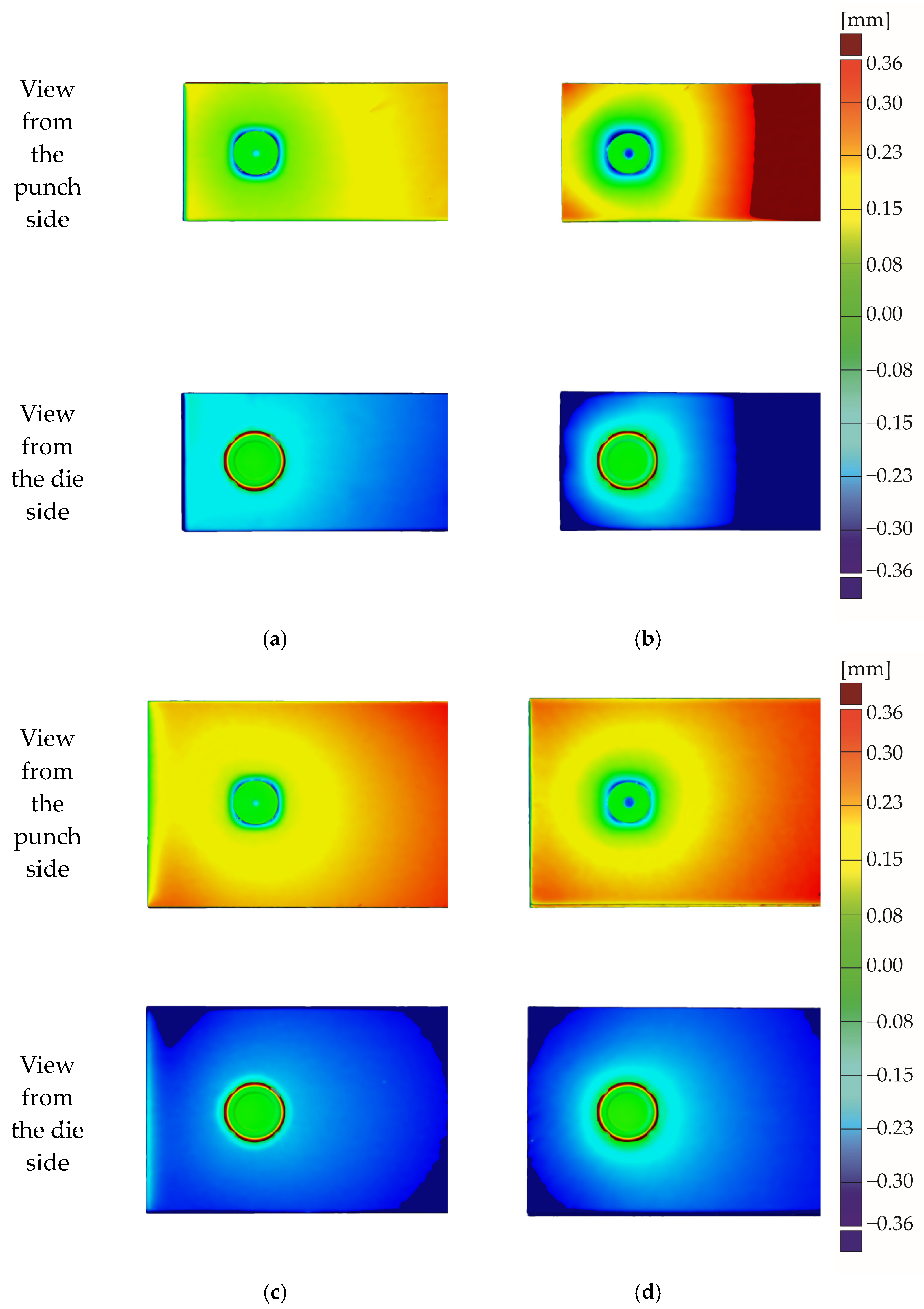
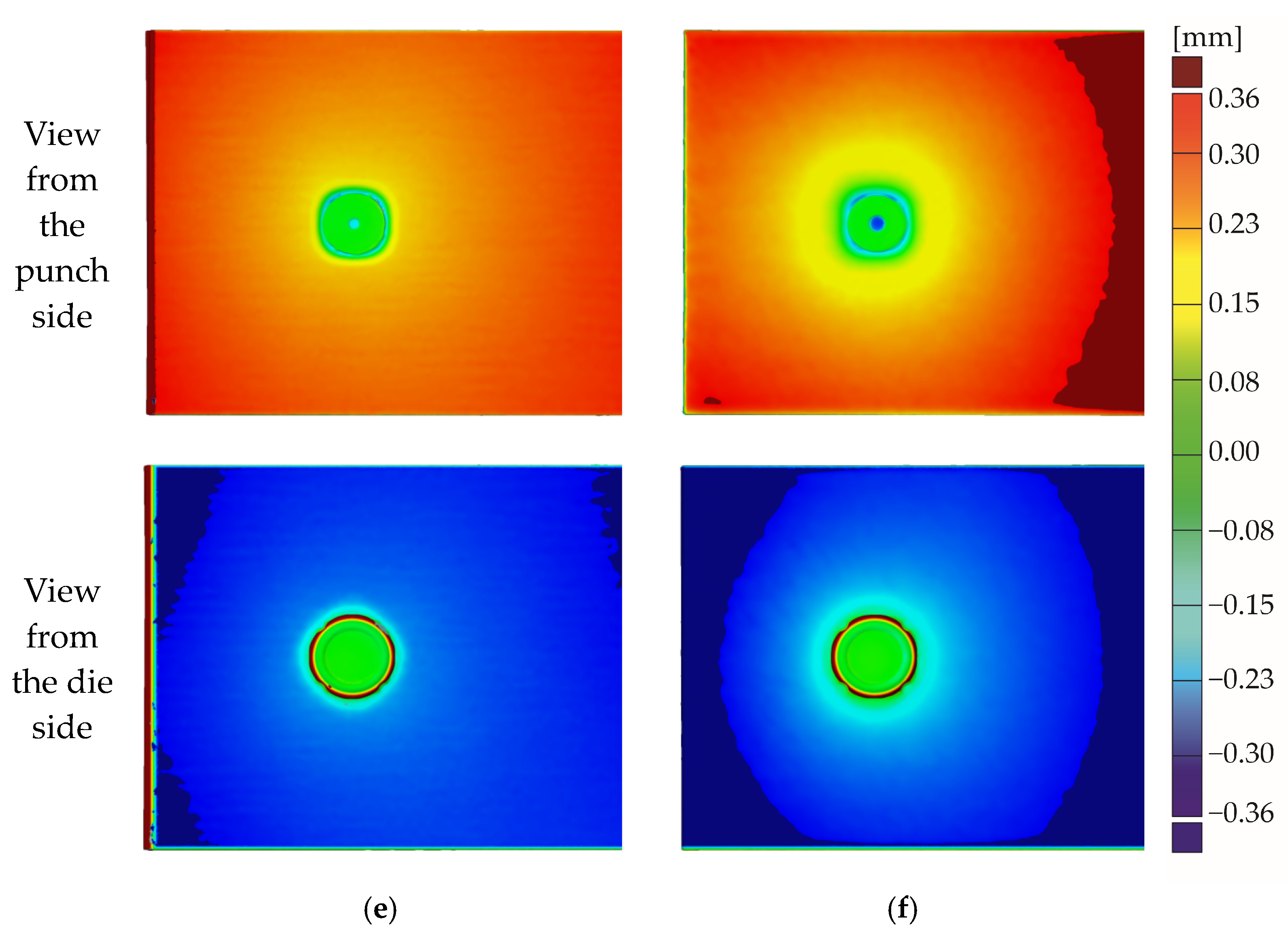
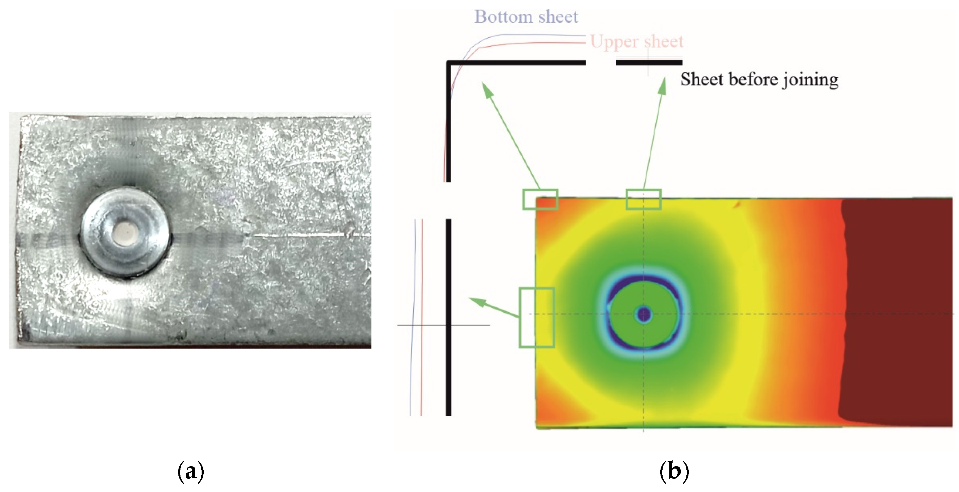
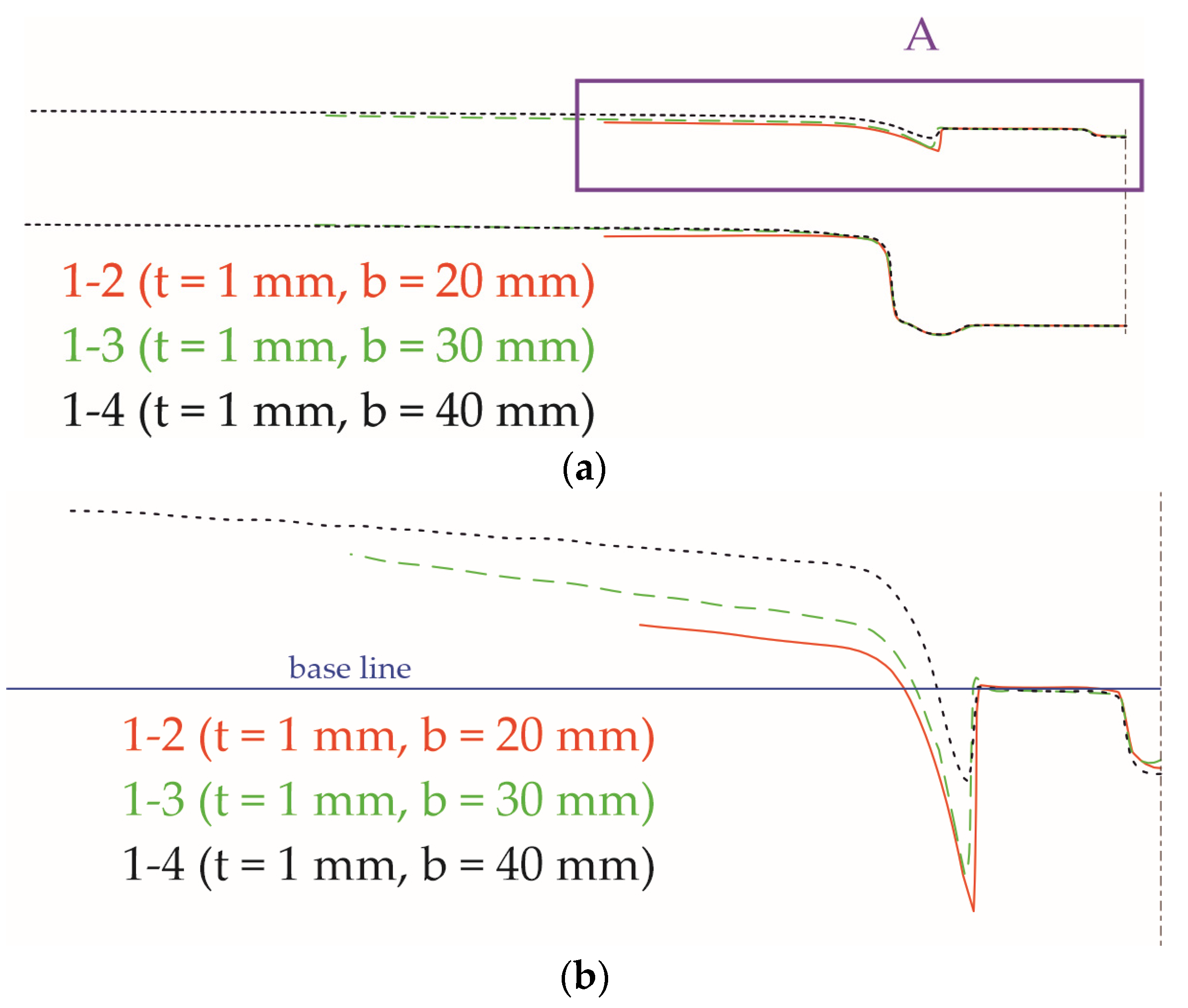
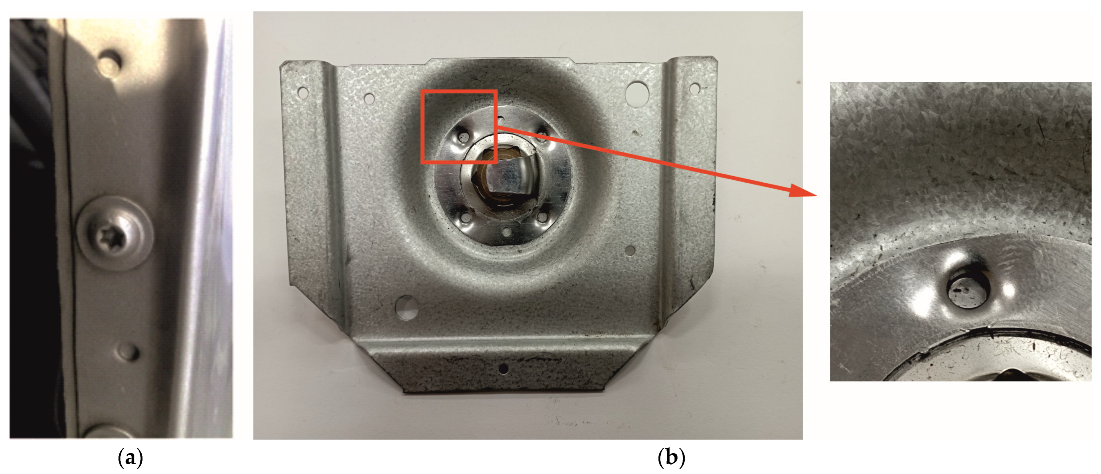
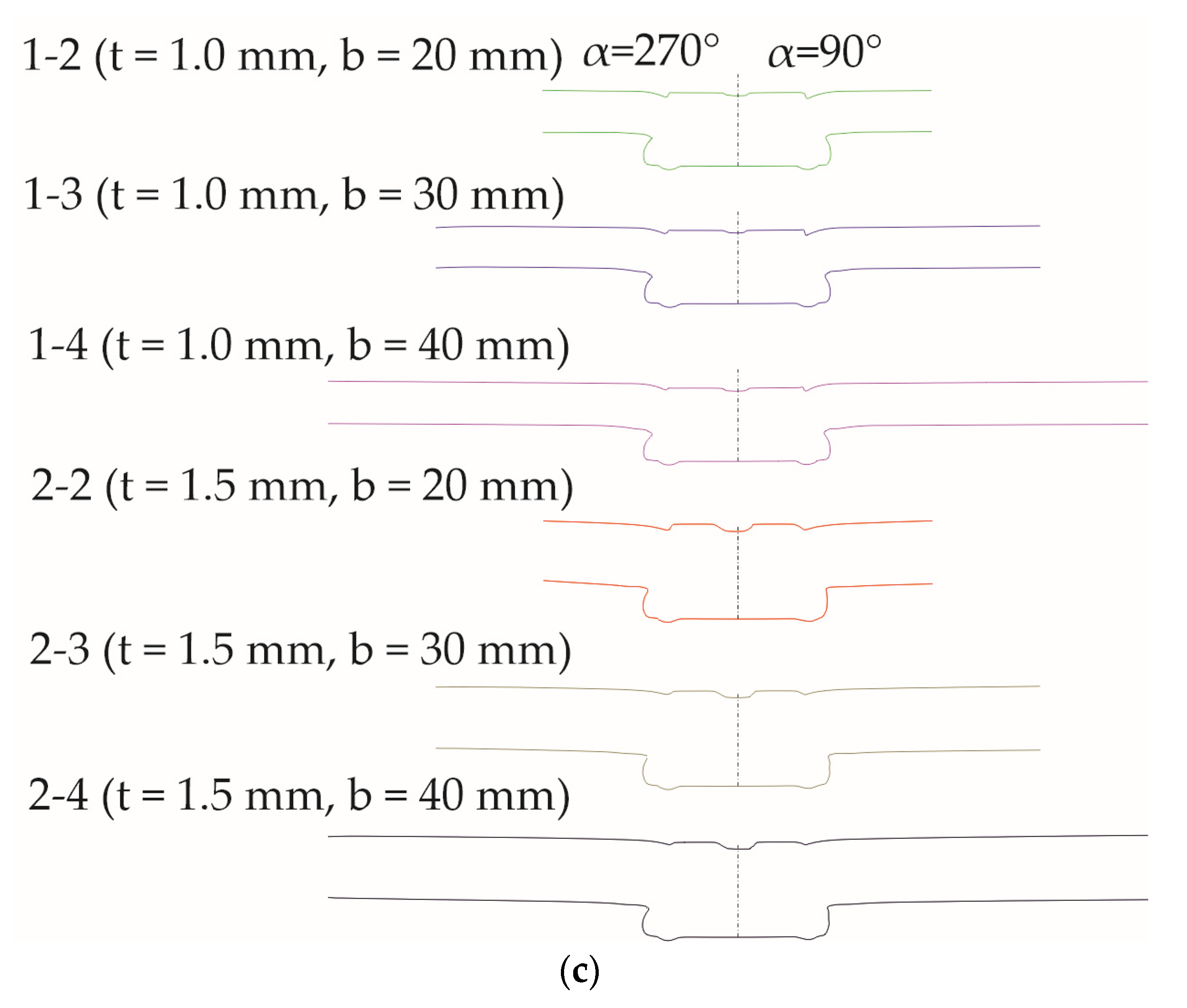
3.3. Sheet Deformation Measurement after Joining Process

Based on the permanent elements of the die, i.e., the flat surface of the die bottom, the groove on the die bottom, and the side surfaces of the sheets, coordinate systems were created for all joints. The surface and torus fitting parameters are presented in Table 6.
In the area close to the rivet, the measurement system did not ensure appropriate values. For the position of the punch system at the level of the upper surface of the sheet, as recommended by the TOX manufacturer, the joints of 1 mm sheet thickness at the point of contact with the punch had a larger size. This was due to the greater pressing of the rivet—the distance between die and punch was smaller than for joints with 1.5 mm sheet thickness. In addition, the Rmin value of 3.75 mm was selected to eliminate defects on the mesh after the process of the polygonization of measurement data, presented in Figure 15 below as sub-points 1 to 5 (places where light reflections occurred, resulting in the lack of a scanned area or a representation deviating from reality) in connection with the adopted measurement method.
For determining the sheet deformation, after the clinch riveting process, all joints were scanned using the ATOS scanner. Deformations of lower and upper sheets in the area of each joint were analyzed on the basis of the 3D model obtained from the measurement. The parts of the samples in the equipment grip area were not taken into account for result analysis. In Figure 16, the views of the 3D model from lower and upper sheets are presented.
For each sample, the shape of the deformation, in the area close to the rivet, reproduced the shape of the die with movable segments—see Figure 16. For fixed segments of the die, from the rivet side close to the rivet, the sheet deformation along the measurement angle α values equal to 45°, 135°, 225°, and 315° was bigger than for angles 0°, 90°, 180°, and 270°. The movement of the die’s sliding element meant that more sheet material could flow in the space between the fixed part of the die and movable segments (Figure 17). Hence the sheet deformation in these places was smaller than for the die’s fixed element—the sheet material was less compressed. Deformations of the sheet, with an increase in the distance between the rivet axis and measuring point, were changing to circular shapes. By increasing the sheet width, the areas of upper and lower sheet deformation lower than ±0.1 mm significantly decreased. The material close to the sheet edges, for 40 mm sheet width, did not allow to change the sheet dimensions.
For the sheet thickness values of 1.5 mm and width 20 mm, the bulk (the rivet pressed in the sheets caused the sheet material to flow) of the sheet appeared along the 180° angle—see Figure 16b. For lower sheet dimensions between the rivet axis and sheet edge (angle 180°), there was an increase of 0.11 mm, and for upper sheets, an increase of 0.09 mm—the linearity deviation. The sheet width at the sheet corners was also changed from 20 mm to 20.34 mm for lower sheets and 20.19 mm for upper sheets. For the 90° and 270° angles, the sheet material was partially blocked by sheet material along the measurement grip area—the sample dimension was changed to 20.34 mm for the lower sheet and 20.19 mm for the upper sheet. The material of the sheet along the 0° angle did not allow to push outside the sheet material. For other sheet widths (30, 40 mm) and the sheet thickness of 1.5 mm and for all samples of 1.00 mm, the change in width observed was 0.03 mm. The linearity deviation of a sheet is presented in Table 7. For the sheet thickness values of 1.0 mm and 1.5 mm and width value of 40 mm, the measured deformations are presented in Table 8. The measurement-point coordinates for 3D models for all joints are presented in Figure 7. The origin point of the axis system was always at the center point of the die bottom. The linearity deviations for other sheet width and thickness values were at a similar level—about 0.02 mm. So, the sheet dimension after the joining process significantly changed only for a sheet width of 20 mm and thickness of 1.0 mm. A view of the joint from the rivet side for the 20 mm sheet width and at a distance of 10 mm from the edge is shown in Figure 18a. In a place where the material has less resistance to movement, it is pushed out so that deformations occur of the edges of the sheet metal near the joint.
For all joints, based on the 3D models, the sheet profiles after the clinch-riveting joining process were determined along the angles α = 0°, 45°, 90°, 180°, 225°, and 270°—see Figure 19.
For a sheet width of 20 mm (Figure 20—red line) and a thickness of 1.5 mm, it can be seen that the deformation of the upper and lower sheets in the area of the rivet is greater than for the widths of 30 mm (Figure 20—green line) and 40 mm (Figure 20—black line). A smaller amount of material around the joint causes a sheet to deform more freely than in the case of wider sheet samples.
For sheets with a thickness of 1 mm, the blank holder means that for smaller widths, the sheet material around it is pressed deeper—see Figure 21. In the case of thinner sheet metal (1.0 mm), in this study, the sheet bend was much closer to the rivet axis (Figure 20 and Figure 21). The bending radius of a 1.5 mm thick sheet was larger compared to the joints of 1.0 mm thick sheets. A greater thickness of the sheets in a joint resulted in a greater (or smaller) deviation from the initial position near the edges of the samples (Figure 16). The wider the sheet metal sample was, the stiffer it was, and the place of bending on the sheet was closer to the initial position of the upper surface of the sheet (Figure 21b).
Changing the thickness of the joined sheets from 1.0 mm (Figure 22—red line) to 1.5 mm (Figure 22—green line) with the same geometry of the forming die and the rivet means that more material fills the same space in the die, which causes greater deformations in the joint area. For the angle α = 225°, the deformation is higher due to a lower stiffness of the sheet than for angle α = 45°.
The range and size of sheet deformation for the angles α = 0° and α = 180° were almost identical for all tested variants. Slight differences were visible for the width of 20 mm and the thickness of 1.5 mm. For all angles, the courses of sheet deformation were the same. There were slight differences in the values of deformation caused by the sheet material flow during the joint formation. In Figure 23, the joint profile in the die groove (green line) and profile in the space of movable segments (red line) are compared.
In places where there were fixed elements on the die (Figure 4a), the sheet material had limited movement. Therefore, there were differences in the geometry of the joint in the planes defined as α = 0° and α = 45° (Figure 23). The material pressed into the die shape encountered permanent segments. The material was pushed into the space created by the movable segments (Figure 17). This system of movement of the sheet material caused different deflections of the sheet surfaces in specific cross-sections (Figure 23).

4. Conclusions

In this paper, the analysis of the DX51D steel sheet deformation after the clinch riveting process has been presented. For two different sheet thickness values (1.0 mm and 1.5 mm) and three sheet width values (20, 30 and 40 mm), the forming forces and deformation of sheets were measured. The influence of the angle between die movable segments and sheet contours on the profile shape was measured. The conducted research and results led to conclusions. The most important conclusions are as follows:
  • The energy consumption of the forming force and the forming process can be reduced by reducing the distance between the joint axis and the edge of the sheet. The forming force was reduced by 2.95% for sheets with a thickness of 1 mm and by 2.65% for sheets with a thickness of 1.5 mm when the distance between the joint axis and the edge of the sheet was reduced from 20 mm to 10 mm.
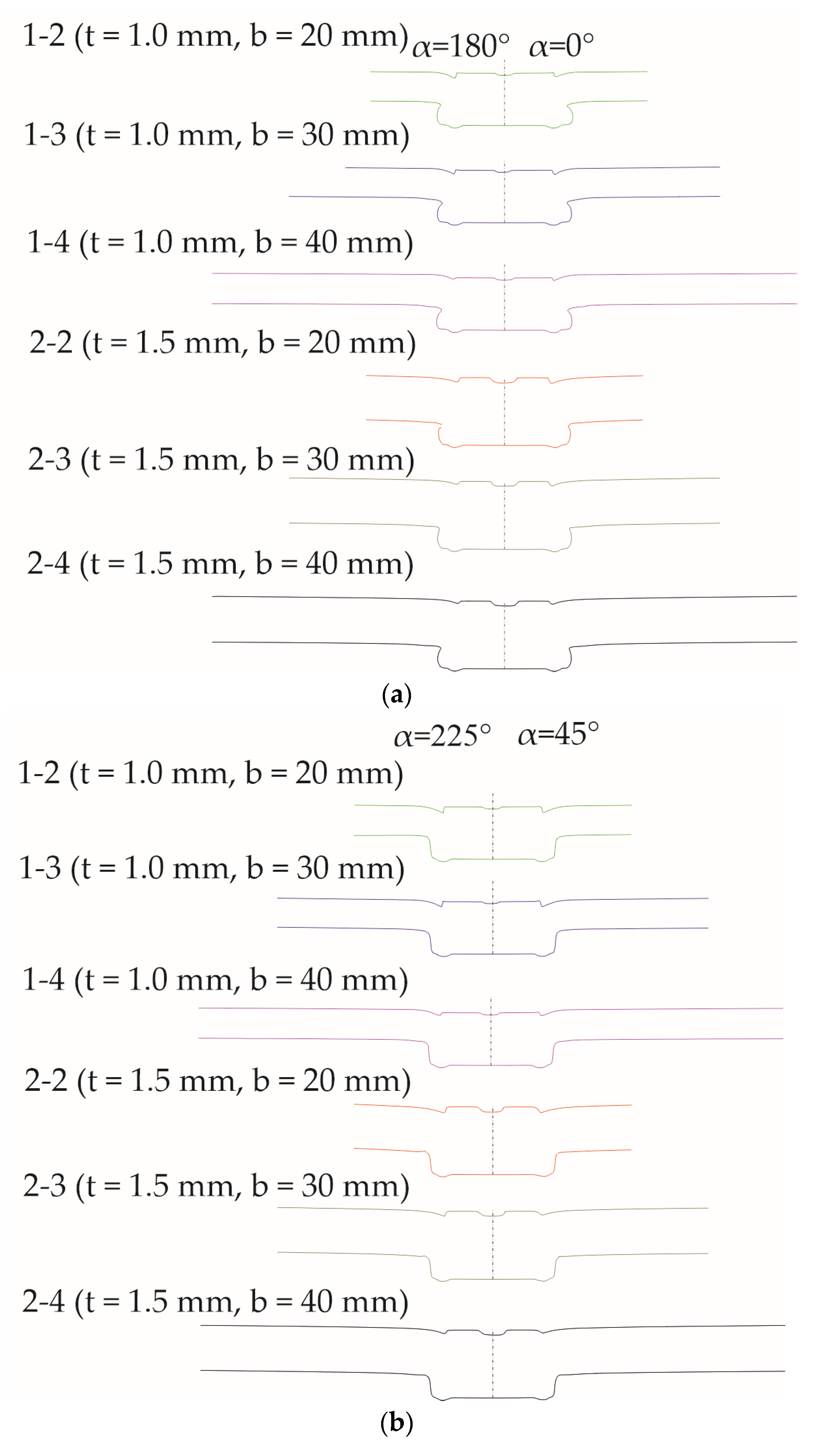
  • The deformation of a sheet depends on the angle between the movable segments and the edge of the sheet. For angles α = 0° and α = 180°, there were no differences in sheet deformation despite the fact that for 180°, there was less material at the sheet edge than for 0°.
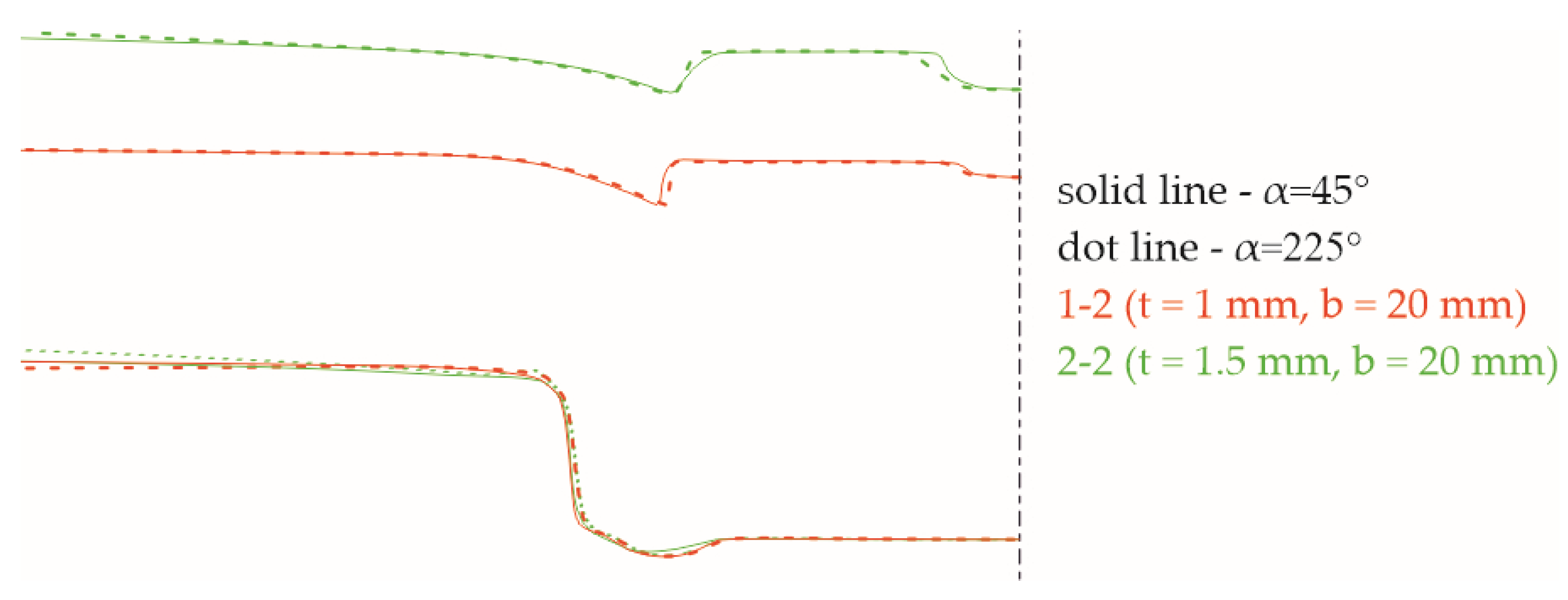
  • The differences in the sheet deformation for angles α = 45° and α = 225° are caused by the lower stiffness of the sheet from the closer edge (α = 225°).
  • For a small distance between the joint axis and the edge of the sheet, the bulk can be obtained. For a sheet width of 20 mm and thicknesses of 1 mm and 1.5 mm, the material of the sheet was pushed more intensively in the radial directions for all angles except 0°—the sheet material along 0° blocked sheet deformation in that direction.

Author Contributions

Conceptualization, W.W., Ł.B. and J.M.; methodology, W.W., J.M. and Ł.B.; software, W.W.; validation, W.W. and Ł.B.; formal analysis, W.W. and J.M.; investigation, Ł.B., J.M. and W.W.; resources, J.M.; data curation, Ł.B.; writing—original draft preparation, W.W.; writing—review and editing, J.M. and Ł.B.; visualization, W.W., Ł.B. and J.M.; supervision, J.M.; project administration, W.W.; funding acquisition, Ł.B., J.M. and W.W. All authors have read and agreed to the published version of the manuscript.

Funding

This research received no external funding.

Institutional Review Board Statement

Not applicable.

Informed Consent Statement

Not applicable.

Data Availability Statement

The data presented in this study are available on request from the corresponding author due to privacy.

Conflicts of Interest

The authors declare no conflict of interest.

References

  1. Leite, W.O.; Campos Rubio, J.C.; Mata, F.; Hanafi, I.; Carrasco, A. Dimensional and Geometrical Errors in Vacuum Thermoforming Products: An Approach to Modeling and Optimization by Multiple Response Optimization. Meas. Sci. Rev. 2018, 3, 113–122. [Google Scholar] [CrossRef]
  2. Valíček, J.; Harničárová, M.; Kušnerová, M.; Zavadil, J.; Grznárik, R. Method of Maintaining the Required Values of Surface Roughness and Prediction of Technological Conditions for Cold Sheet Rolling. Meas. Sci. Rev. 2014, 3, 144–151. [Google Scholar] [CrossRef]
  3. Hultman, H.; Cedergren, S.; Wärmefjord, K.; Söderberg, R. Predicting Geometrical Variation in Fabricated Assemblies Using a Digital Twin Approach Including a Novel Non-Nominal Welding Simulation. Aerospace 2022, 9, 512. [Google Scholar] [CrossRef]
  4. Meschut, G.; Janzen, V.; Olfermann, T. Innovative and Highly Productive Joining Technologies for Multi-Material Lightweight Car Body Structures. J. Mater. Eng. Perform. 2014, 23, 1515–1523. [Google Scholar] [CrossRef]
  5. Eckert, A.; Israel, M.; Neugebauer, R.; Rössinger, M.; Wahl, M.; Schulz, F. Local–global approach using experimental and/or simulated data to predict distortion caused by mechanical joining technologies. Prod. Eng. Res. Devel. 2013, 7, 339–349. [Google Scholar] [CrossRef]
  6. Varis, J.P.; Lepisto, J. A simple testing-based procedure and simulation of the clinching process using finite element analysis for establishing clinching parameters. Thin Wall. Struct. 2003, 41, 691–709. [Google Scholar] [CrossRef]
  7. Zheng, B.; Yu, H.; Lai, X. Assembly deformation prediction of riveted panels by using equivalent mechanical model of riveting process. Int. J. Adv. Manuf. Technol. 2017, 92, 1955–1966. [Google Scholar] [CrossRef]
  8. He, X.; Wang, Y.; Lu, Y.; Zeng, K.; Gu, F.; Ball, A. Self-piercing riveting of similar and dissimilar titanium sheet materials. Int. J. Adv. Manuf. Technol. 2015, 80, 2105–2115. [Google Scholar] [CrossRef]
  9. Xing, B.; He, X.; Zeng, K.; Wang, Y. Mechanical properties of self-piercing riveted joints in aluminum alloy 5052. Int. J. Adv. Manuf. Technol. 2014, 75, 351–361. [Google Scholar] [CrossRef]
  10. Zhang, X.; He, X.; Gu, F.; Ball, A. Self-piercing riveting of aluminium–lithium alloy sheet materials. J. Mater. Process. Technol. 2019, 268, 192–200. [Google Scholar] [CrossRef]
  11. Zhao, L.; He, X.; Xing, B.; Zhang, X.; Cheng, Q.; Gu, F.; Ball, A. Fretting behavior of self-piercing riveted joints in titanium sheet materials. J. Mater. Process. Technol. 2017, 249, 246–254. [Google Scholar] [CrossRef]
  12. Mucha, J.; Kaščák, L.; Spišák, E. Joining the car-body sheets using clinching process with various thickness and mechanical property arrangements. Arch. Civ. Mech. Eng. 2011, 1, 135–148. [Google Scholar] [CrossRef]
  13. Lee, C.-J.; Shen, G.; Kim, B.-M.; Lambiase, F.; Ko, D.-C. Analysis of failure-mode dependent joint strength in hole clinching from the aspects of geometrical interlocking parameters. Metals 2018, 8, 1020. [Google Scholar] [CrossRef]
  14. Zhang, Y.; He, X.; Wang, Y.; Lu, Y.; Gu, F.; Ball, A. Study on failure mechanism of mechanical clinching in aluminium sheet materials. Int. J. Adv. Manuf. Technol. 2018, 96, 3057–3068. [Google Scholar] [CrossRef]
  15. Abe, Y.; Kato, T.; Mori, K.-I.; Nishino, S. Mechanical clinching of ultra-high strength steel sheets and strength of joints. J. Mater. Process. Technol. 2014, 10, 2112–2118. [Google Scholar] [CrossRef]
  16. Ge, Y.; Xia, Y. Mechanical characterization of a steel-aluminum clinched joint under impact loading. Thin. Wall. Struct. 2020, 151, 106759. [Google Scholar] [CrossRef]
  17. Chen, C.; Zhao, S.; Cui, M.; Han, X.; Fan, S. Mechanical properties of the two-steps clinched joint with a clinch-rivet. J. Mater. Process. Technol. 2016, 237, 361–370. [Google Scholar] [CrossRef]
  18. Grimm, T.; Drossel, W.-G. Process development for self-pierce riveting with solid formable rivet of boron steel in multi-material design. Procedia Manuf. 2019, 29, 271–279. [Google Scholar] [CrossRef]
  19. Neugebauer, R.; Rössinger, M.; Wahl, M.; Schulz, F.; Eckert, A.; Schützle, W. Predicting Dimensional Accuracy of Mechanically Joined Car Body Assemblies. Key Eng. Mater. 2011, 473, 973–980. [Google Scholar] [CrossRef]
  20. Neugebauer, R.; Jesche, F.; Kraus, C.; Hensel, S. Mechanical joining with self piercing solid-rivets at elevated tool velocities. AIP Conf. Proc. 2011, 1353, 1278–1283. [Google Scholar]
  21. Mucha, J. The effect of material properties and joining process parameters on behavior of self-pierce riveting joints made with the solid rivet. Mater. Des. 2013, 52, 932–946. [Google Scholar] [CrossRef]
  22. Mucha, J. The failure mechanics analysis of the solid self-piercing riveting joints. Eng. Fail. Anal. 2015, 47, 77–88. [Google Scholar] [CrossRef]
  23. Neugebauer, R.; Jesche, F.; Israel, M. Enlargement of the application range of solid punch riveting by two-piece dies. Int. J. Mater. Form. 2010, 3, 999–1002. [Google Scholar] [CrossRef]
  24. Mucha, J.; Kaščák, Ľ.; Witkowski, W. Research on the influence of the AW 5754 aluminum alloy state condition and sheet arrangements with AW 6082 aluminum alloy on the forming process and strength of the clinch-rivet joints. Materials 2021, 14, 2980. [Google Scholar] [CrossRef]
  25. Mucha, J.; Boda, Ł.; Witkowski, W. Geometrical parameters and strength of clinching joint formed with the use of an additional rivet. Arch. Civ. Mech. Eng. 2023, 23, 114. [Google Scholar] [CrossRef]
  26. Ren, X.; Chen, C.; Ran, X.; Gao, X.; Gao, Y. Investigation on lightweight performance of tubular rivet-reinforced joints for joining AA5052 sheets. J. Braz. Soc. Mech. Sci. Eng. 2021, 43, 333. [Google Scholar] [CrossRef]
  27. Chen, C.; Wu, J.; Li, H. Optimization design of cylindrical rivet in flat bottom riveting. Thin. Wall. Struct. 2021, 168, 108292. [Google Scholar] [CrossRef]
  28. Mucha, J.; Boda, Ł.; Witkowski, W.; Poręba, M. Mixed-mode loading tests for determining the mechanical properties of clinched joints with an additional rivet used in the assembly of thin-walled structures. Thin Wall. Struct. 2023, 190, 110965. [Google Scholar] [CrossRef]
  29. Chen, C.; Zhang, X.; Wen, C.; Yin, Y. Effect of blank holder force on joining quality of the flat clinch-rivet process. Int. J. Adv. Manuf. Technol. 2022, 121, 6315–6323. [Google Scholar] [CrossRef]
  30. Abe, Y.; Maeda, T.; Yoshioka, D.; Mori, K.-I. Mechanical clinching and self-pierce riveting of thin three sheets of 5000 series aluminium alloy and 980 MPa grade cold rolled ultra-high strength steel. Materials 2020, 13, 4741. [Google Scholar] [CrossRef]
  31. Mori, K.; Abe, Y.; Kato, T.; Sakai, S. Self-pierce riveting of three aluminium alloy and mild steel sheets. AIP Conf. Proc. 2010, 1252, 673–680. [Google Scholar]
  32. Abe, Y.; Kato, T.; Mori, K. Self-pierce riveting of three high strength steel and aluminium alloy sheets. Int. J. Mater. Form. 2008, 1, 1271–1274. [Google Scholar] [CrossRef]
  33. Kaščák, Ľ.; Spišák, E.; Majerníková, J. Joining three car body steel sheets by clinching method. Open Eng. 2016, 6, 566–573. [Google Scholar] [CrossRef]
  34. Kaščák, L.; Spišák, E.; Kubik, R.; Mucha, J. FEM analysis of clinching tool load in a joint of dual-phase steels. Strength Mater. 2016, 48, 533–539. [Google Scholar] [CrossRef]
  35. Karim, M.A.; Murugan, S.P.; Bae, K.; Baek, J.; Ji, C.; Noh, W.; Lee, H.J.; Jang, W.; Kim, D.B.; Park, Y.D. Effect of top sheet materials on joint performance of self-piercing riveting. J. Weld. Join. 2022, 6, 512–524. [Google Scholar] [CrossRef]
  36. Wang, J.; Zhang, G.; Zheng, X.; Li, J.; Li, X.; Zhu, W.; Yanagimoto, J. A self-piercing riveting method for joining of continuous carbon fiber reinforced composite and aluminum alloy sheets. Compos. Struct. 2021, 259, 113219. [Google Scholar] [CrossRef]
  37. Sankaranarayanan, R.; Hynes, N.; Nikolova, M.P.; Królczyk, J.B. Self-pierce riveting: Development and assessment for joining polymer—Metal hybrid structures in lightweight automotive applications. Polymers 2023, 15, 4053. [Google Scholar] [CrossRef]
  38. Jäckel, M.; Grimm, T.; Niegsch, R.; Drossel, W.-G. Overview of current challenges in self-pierce riveting of lightweight materials. Proceedings 2018, 2, 384. [Google Scholar]
  39. Gröger, B.; Troschitz, J.; Vorderbrüggen, J.; Vogel, C.; Kupfer, R.; Meschut, G.; Gude, M. Clinching of thermoplastic composites and metals—A comparison of three novel joining technologies. Materials 2021, 9, 2286. [Google Scholar] [CrossRef] [PubMed]
  40. Galińska, A.; Galiński, C. Mechanical Joining of Fibre Reinforced Polymer Composites to Metals—A Review. Part II: Riveting, Clinching, Non-adhesive form-locked joints, pin and loop joining. Polymers 2020, 8, 1681. [Google Scholar] [CrossRef] [PubMed]
  41. Lambiase, F.; Scipioni, S.I.; Lee, C.-J.; Ko, D.-C.; Liu, F. A state-of-the-Art review on advanced joining processes for metal-Composite and metal-Polymer hybrid structures. Materials 2021, 8, 1890. [Google Scholar] [CrossRef]
  42. Lambiase, F. Mechanical behaviour of polymer–metal hybrid joints produced by clinching using different tools. Mater. Des. 2015, 87, 606–618. [Google Scholar] [CrossRef]
  43. Lambiase, F.; Durante, M. Mechanical behavior of punched holes produced on thin glass fiber reinforced plastic laminates. Compos. Struct. 2017, 173, 25–34. [Google Scholar] [CrossRef]
  44. Meschut, G.; Gude, M.; Augenthaler, F.; Geske, V. Evaluation of damage to carbon-fibre composites induced by self-pierce riveting. Procedia CIRP 2014, 18, 186–191. [Google Scholar] [CrossRef]
  45. Lambiase, F.; Paoletti, A. Friction-assisted clinching of aluminum and CFRP sheets. J. Manuf. Process. 2018, 31, 812–822. [Google Scholar] [CrossRef]
  46. Vorderbrüggen, J.; Köhler, D.; Grüber, B.; Troschitz, J.; Gude, M.; Meschut, G. Development of a rivet geometry for solid self-piercing riveting of thermally loaded CFRP-metal joints in automotive construction. Compos. Struct. 2022, 291, 115583. [Google Scholar] [CrossRef]
  47. Wiesenmayer, S.; Graser, M.; Merklein, M. Influence of the properties of the joining partners on the load-bearing capacity of shear-clinched joints. J. Mater. Process. Technol. 2020, 283, 116696. [Google Scholar] [CrossRef]
  48. Wiesenmayer, S.; Merklein, M. Potential of shear-clinching technology for joining of three sheets. J. Adv. Join. Process. 2021, 3, 100043. [Google Scholar] [CrossRef]
  49. Latorre, N.; Casellas, D.; Costa, J. A mechanical interlocking joint between sheet metal and carbon fibre reinforced polymers through punching. IOP Conf. Ser. Mater. Sci. Eng. 2023, 1284, 012001. [Google Scholar] [CrossRef]
  50. Lin, P.-C.; Fang, J.-C.; Lin, J.-W.; Tran, X.V.; Ching, Y.-C. Preheated (Heat-Assisted) Clinching Process for Al/CFRP Cross-Tension Specimens. Materials 2020, 13, 4170. [Google Scholar] [CrossRef] [PubMed]
  51. Witkowski, W.; Kurc, K. Shape deformation of the clinching joints upper sheet. Mechanik 2018, 91, 253–255. [Google Scholar] [CrossRef]
  52. Ren, X.; Chen, C.; Gao, X.; Qin, D.; Ouyang, Y. The effect of clinching process on mechanical properties of the single strap butt joint. J. Braz. Soc. Mech. Sci. Eng. 2022, 44, 134. [Google Scholar] [CrossRef]
  53. Tozaki, Y.; Uematsu, Y.; Tokaji, K. Effect of tool geometry on microstructure and static strength in friction stir spot welded aluminium alloys. Int. J. Mach. Tools Manuf. 2007, 47, 2230–2236. [Google Scholar] [CrossRef]
  54. Cai, W.; Lesperance, R.M.; Marin, S.P.; Meyer, W.W.; Oetjens, T.J. Digital Panel Assembly for Automotive Body-in-White. In Proceedings of the ASME 2002 International Mechanical Engineering Congress and Exposition, New Orleans, LA, USA, 17–22 November 2002; ASME: New York, NY, USA, 2008; pp. 453–466. [Google Scholar] [CrossRef]
  55. Cai, W.; Wang, P.C.; Yang, W. Assembly dimensional prediction for self-piercing riveted aluminum panels. Int. J. Mach. Tools Manuf. 2005, 45, 695–704. [Google Scholar] [CrossRef]
  56. Pinger, T.; Rückriem, E.M. Investigation on the corrosion and mechanical behavior of thin film batch galvanized thick plate components in clinch joints. Int. J. Adv. Manuf. Technol. 2016, 86, 29–36. [Google Scholar] [CrossRef]
  57. Mhawesh, Z.T.; Kara, İ.H.; Zeyvel, M. Corrosion resistance of interstitial free steel and Mg alloys sheets joined by mechanical clinching. J. Mater. Eng. Perform. 2023, 32, 2793–2800. [Google Scholar] [CrossRef]
  58. EN 10327:2004; Continuously Hot-Dip Coated Strip and Sheet of Low Carbon Steels for Cold Forming. Technical Delivery Conditions. CEN: Brussels, Belgium, 2004.
  59. ISO 6507-1:2018; Metallic Materials—Vickers Hardness Test—Part 1: Test Method. Technical Committee ISO/TC 164, Mechanical Testing of Metals, Subcommittee SC 3, Hardness Testing. ISO: Geneva, Switzerland, 2018.
  60. VDI/VDE 2634-3:2008-12; Optical 3D-Measuring Systems—Multiple View Systems Based on Area Scanning. Beuth Verlag GmbH: Berlin, Germany, 2008.
  61. Boda, Ł.; Mucha, J.; Witkowski, W. Performance Tests of HX340 Microalloyed Steel Sheets Joined Using Clinch-Rivet Technology. Materials 2024, 17, 596. [Google Scholar] [CrossRef]
Figure 1. Example of the clinch joint formed close to the sheets edge: (a) aluminum alloy sheets; (b) thin stainless steel sheet and thick carbon steel sheet.
Metals 14 00367 g001
Figure 2. The characteristics of sheet deformation in clinch riveting process (a) before joining, (b) after punch retract, and (c) after die retract.
Metals 14 00367 g002
Figure 3. The C-frame stand for forming CR joints: (a) C-frame machine; (b) cross-section of the punch system with rivet feeder.
Metals 14 00367 g003
Figure 4. The basic forming tools used in clinch riveting technology: (a) die, (b) punch system, and (c) rivet.
Metals 14 00367 g004
Figure 5. The force–displacement diagram of clinch riveting process.
Metals 14 00367 g005
Figure 6. The sample and measuring area dimensions: (a) before joining; (b) after joining.
Metals 14 00367 g006
Figure 7. The scheme of the measurements: (a) position of the movable segments of the die; (b) radius dimensions; (c) angles for joint cross-sections.
Metals 14 00367 g007
Figure 8. The measurement stand with 3D ATOS Capsule scanner.
Metals 14 00367 g008
Figure 9. The summary of the performed measurement series, with a specification of one shot as comprising 2 photos.
Metals 14 00367 g009
Figure 10. The measurement coordinate system (a) and elements used for determining and positioning axis system (b).
Metals 14 00367 g010
Figure 11. The force–displacement diagrams of clinch riveting process for one sample combination (seven samples, b = 20 mm, t = 1 mm)—diagrams move by each other at a distance of 0.5 mm.
Metals 14 00367 g011
Figure 12. The comparison of the force–displacement diagrams of clinch riveting process.
Metals 14 00367 g012
Figure 13. The comparison of joint interlocks (α = 90°): (a) 20 mm × 1 mm, (b) 20 mm × 1.5 mm, (c) 30 mm × 1 mm, (d) 30 mm × 1.5 mm, (e) 40 mm × 1 mm, and (f) 40 mm × 1.5 mm.
Metals 14 00367 g013
Figure 14. The results of the sheet deviation before joining.
Metals 14 00367 g014
Figure 15. Sample of the mesh grid (a) and the measurement mesh defects close to the punch–sheet contact area (b) points 1–5 are the places where light reflections occurred.
Metals 14 00367 g015
Figure 16. Samples of the sheet deformations with clinch-rivet joints for sheet width b and thickness t: (a) 20 mm × 1 mm, (b) 20 mm × 1.5 mm, (c) 30 mm × 1 mm, (d) 30 mm × 1.5 mm, (e) 40 mm × 1 mm, and (f) 40 mm × 1.5 mm.
Metals 14 00367 g016aMetals 14 00367 g016b
Figure 17. The scheme of the sheet material flow in CR joining process.
Metals 14 00367 g017
Figure 18. Example of sheet deformation in a clinch-rivet joint (sheet thickness t = 1.5 mm, sheet width b = 20 mm): (a) real view from the die side; (b) view from punch side of the joint CAD model.
Metals 14 00367 g018
Figure 19. Profiles of the sheets: (a) α = 0° and α = 180°; (b) α = 45° and α = 225°; (c) α = 90° and α = 270°.
Metals 14 00367 g019aMetals 14 00367 g019b
Figure 20. Profiles of the sheet with 1.5 mm thickness (α = 45°): (a) half of the cross-section, (b) 10× zoom in y axis of A area.
Metals 14 00367 g020
Figure 21. Profiles of the sheet with 1.0 mm thickness (α = 45°): (a) half of the cross-section; (b) 10× zoom in y axis of A area.
Metals 14 00367 g021
Figure 22. Profiles of the sheet with 20 mm width and angles α = 45° and α = 225° (sheet thickness 1.5 mm—green line and 1 mm—red line).
Metals 14 00367 g022
Figure 23. Profiles of the sheet with 20 mm width (α = 0°—green line and α = 45°—red line).
Metals 14 00367 g023
Table 1. Mechanical properties of DX51D+Z275 sheets.
Material DesignationSurface Finish + Z
[g/m2]
Young’s Modulus
E [GPa]
Poisson’s Ratio
ν [–]
Yield Strength Rp0.2 [MPa]Tensile Strength
Rm [MPa]
Elongation after Fracture
A80 [%]
DX51D+Z275zinc layer quality 2751880.333043829
Table 2. Chemical composition of DX51D+Z275 sheets (maximum percentage by weight [%]).
MnSiTiCPSFe
1.20.50.30.180.120.045rest
Table 3. The dimensions of the measurement radius.
Sheet Width b [mm]Sheet Thickness t [mm]Rmin [mm]Rmax [mm]
2013.759
3013.7514
4013.7519
201.53.759
301.53.7514
401.53.7519
Table 4. Mean values of forming force and statistical parameters.
Sample
Nomenclature
Sheet Width
b [mm]
Sheet Thickness
t [mm]
Forming Force
Ff [kN]
Standard Deviation s [kN]Coefficient of Variation cv [%]Forming Energy Ef [J]
1-220185.180.3980.467232
1-330187.350.3970.454236
1-440187.770.4260.485237
2-2201.572.320.3980.550210
2-3301.574.570.3560.477218
2-4401.574.290.4160.560213
Table 5. Values of the sheet dimensions and deviations (average values).
Measured ParameterValues
Sheet thickness t [mm]1
Manufacturer sheet thickness tolerance [mm]±0.07
Measured sheet thickness [mm]0.98
Sheet width b [mm]20, 30, 40
Sheet width tolerance [mm]±0.1
Measured sheet width [mm]20.07, 30.05, 40.03
Sheet thickness t [mm]1.5
Manufacturer sheet thickness tolerance [mm]±0.11 mm
Measured sheet thickness [mm]1.45
Sheet width b [mm]20, 30, 40
Sheet width tolerance [mm]±0.1
Measured sheet width [mm]20.05, 30.06, 40.03
Table 6. The results of geometry fitting used for the determining of the axis system.
Adjustment ResultSheet Dimensions b × t [mm × mm]
20 × 130 × 140 × 120 × 1.530 × 1.540 × 1.5
Fitting plane (axis Z = 0.0 mm)Minimum mm−0.031−0.004−0.005−0.0036−0.0045−0.0049
Maximum mm0.00450.00680.00730.00410.00580.0046
Sigma mm0.0020.00290.00360.00220.00290.0028
Residual mm0.00170.00240.00310.00190.00240.0025
Number of nodes for base creation608691904521568631
Fitting torus (axes X = 0.0. Y = 0.0 mm)Minimum mm−0.0187−0.0219−0.0142−0.0196−0.0297−0.0187
Maximum mm0.01970.02160.01030.01280.01480.0139
Sigma mm0.00690.0740.00490.00620.00860.0068
Residual mm0.00540.00570.00390.00490.00650.0053
Table 7. The sheet linearity deviation after clinch riveting process.
Sample Nomenclature1-21-31-42-22-32-4
Sheet thickness t [mm]1111.51.51.5
Sheet width b [mm]203040203040
Lower sheet dimension for angle 90° and 270°0.290.040.020.030.010.01
Upper sheet dimension for angle 90° and 270°0.140.030.010.010.020.01
Lower sheet dimension for angle 180°0.110.030.030.020.010.01
Upper sheet dimension for angle 180°0.090.020.030.020.010.01
Average sheet width before joining [mm]20.0730.0540.0320.0530.0640.03
Table 8. Measurements of profile point deviations for clinch-riveted joints made for 40 mm width sheets.
Sheet thickness t [mm]1111111.51.51.51.51.51.5
Measurement angle α [°]45°90°180°225°270°45°90°180°225°270°
Values of the point deviations
Measurement radius R [mm]
3.750.08−0.030.030.06−0.050.070.02-0.07-0.020.01-0.060.02
4.000.140.050.100.130.050.140.05-0.010.020.05-0.010.05
4.250.170.110.140.170.110.180.080.020.050.070.030.08
4.500.190.150.170.190.150.20.100.050.070.090.050.10
4.750.200.170.190.200.180.210.110.080.090.100.070.11
5.000.210.190.200.200.200.220.130.090.100.110.090.13
5.250.210.190.200.210.210.220.130.110.110.120.10.14
5.500.210.200.200.210.210.220.140.120.120.130.120.14
5.750.210.200.200.210.220.220.150.130.130.130.130.15
6.000.210.200.200.220.220.220.150.140.140.140.130.15
7.000.220.210.210.220.220.230.170.160.160.160.160.17
8.000.230.220.220.230.240.240.190.180.180.180.180.19
9.000.240.230.230.240.240.240.210.200.190.200.200.20
10.000.240.230.240.250.250.250.220.220.210.210.220.22
11.000.250.240.240.260.260.260.230.220.220.220.230.23
12.000.250.240.250.270.270.260.240.240.240.230.240.24
13.000.260.250.250.270.270.270.260.250.250.240.260.25
14.000.270.260.260.280.280.270.270.260.260.250.260.26
15.000.270.260.260.290.290.270.280.270.270.260.270.27
16.000.270.270.270.30.290.280.290.280.280.270.290.28
17.000.280.270.270.30.30.280.30.290.290.280.290.29
18.000.290.280.270.310.30.290.310.30.30.280.30.3
19.000.290.280.280.320.310.290.320.310.310.260.310.3
Disclaimer/Publisher’s Note: The statements, opinions and data contained in all publications are solely those of the individual author(s) and contributor(s) and not of MDPI and/or the editor(s). MDPI and/or the editor(s) disclaim responsibility for any injury to people or property resulting from any ideas, methods, instructions or products referred to in the content.

