Article

The Separation Behavior of TiB2 during Cl2-Free Degassing Treatment of 5083 Aluminum Melt

1
IME Process Metallurgy and Metal Recycling, RWTH Aachen University, 52056 Aachen, Germany
2
Department of Materials Science and Engineering, Izmir Institute of Technology, Izmir 35430, Turkey
3
Foseco Nederland BV, Pantheon 30, 7521 PR Enschede, The Netherlands
*
Authors to whom correspondence should be addressed.
Metals 2024, 14(4), 402; https://doi.org/10.3390/met14040402
Submission received: 21 February 2024 / Revised: 20 March 2024 / Accepted: 26 March 2024 / Published: 29 March 2024

Abstract

:
Utilizing titanium diboride (TiB2) inoculation for grain-refining purposes is a widely established practice in aluminum casthouses and foundries. Since this inoculation is usually implemented jointly with or between routine melt treatment steps ahead of casting, it is important to know whether and how other melt treatment processes affect the fade of TiB2 particles. For the present study, we investigated the influence of degassing process on the separation behavior of TiB2 particles in aluminum melt. Multiple sampling methods were employed and the samples were analyzed via spectrometer analysis. The removal efficiency of TiB2 during the gas-purging process of 5083 aluminum melt was confirmed to be significant over 10 min of treatment time. The rate at which the TiB2 content decays was found to increase with the impeller rotary speed from 400 rounds per minute (rpm) to 700 rpm. The separation rate of TiB2 particles was obtained to be 0.05–0.08 min−1 by fitting the experimental data. Particle mapping results suggest that the TiB2 particles were separated to a dross layer. The obtained experimental results were used to quantitatively evaluate the conventional deterministic flotation model. The deviation between the conventional model and the experimental data was explained through the entrainment–entrapment (EE) model. Suggestions were made for future analytical and experimental works which may validate the EE model.

1. Introduction

Titanium diboride (TiB2) inoculation is among one of the most effective methods for refining the grain structure of aluminum alloys [1,2]. The refinement of the grain size leads to many benefits such as mechanical properties and workability. In industrial practices, this inoculation is realized through Al-Ti-B master alloys [3]. The addition of the master alloy is always carried out ahead of metal casting. However, the site of addition varies between casthouses and foundries. On one hand, a good TiB2 inoculation practice provides sufficient time for the master alloy to dissolve and for TiB2 particles to disperse in the melt [1]. On the other hand, caution needs to be exercised to avoid the decay of TiB2 particles during different melt-handling steps, i.e., salt fluxing [4], melt transfer [5], melt holding, degassing [6,7], and filtration [8,9,10]. In order to determine the best location and timing for TiB2 inoculation, it is imperative to know whether these melt-handling steps remove or lead to decay of the TiB2 particles.
Degassing treatment is often seen as a critical step for melt treatment [11,12,13]. Being performed via batch degassers or in-line degassing stations, the beneficial effects of degassing treatment with regard to H2 and alkali metal removal have been well acknowledged [14]. In the meantime, the degassing process was reported to be able to remove certain types of inclusions such as oxides and carbide [15]. The influence of degassing treatment on TiB2 particles’ separation behavior, nevertheless, has not been reported on a frequent basis. Among the limited number of relevant publications, controversies exist surrounding the significancy of TiB2 removal during degassing treatment and the relevant principle (if removal takes place). In this study, publications since the 1980s were assessed and these results are summarized in Table 1 along with the corresponding experimental conditions. It can be seen that the removal extent of TiB2 varies from negligible to significant among different studies. With respect to the principle of TiB2 removal, sedimentation and floatation principles were proposed. The proposed principles were, however, not closely examined via analytical and experimental approaches.
The present study, funded by Advanced Metals And Processes (AMAP) Open Innovation Research Cluster, was conducted with an aim to clarify the significance of TiB2 separation during the Cl2-free degassing process and understand the underlying principles. The time-dependent variation in TiB2 concentration in the melt during the melt degassing process was monitored in a 5 kg degassing unit. Meanwhile, the spatial distribution of TiB2 along the melt-depth direction was measured to clarify the separation principle. The impact of impeller rotary speed on the separation kinetics of TiB2 was also investigated. A conventional deterministic flotation model was evaluated quantitatively using experimental data. An entrainment–entrapment (EE) model was proposed to account for the deviation between the conventional flotation model and the experimental data.

2. Experimental Methodology

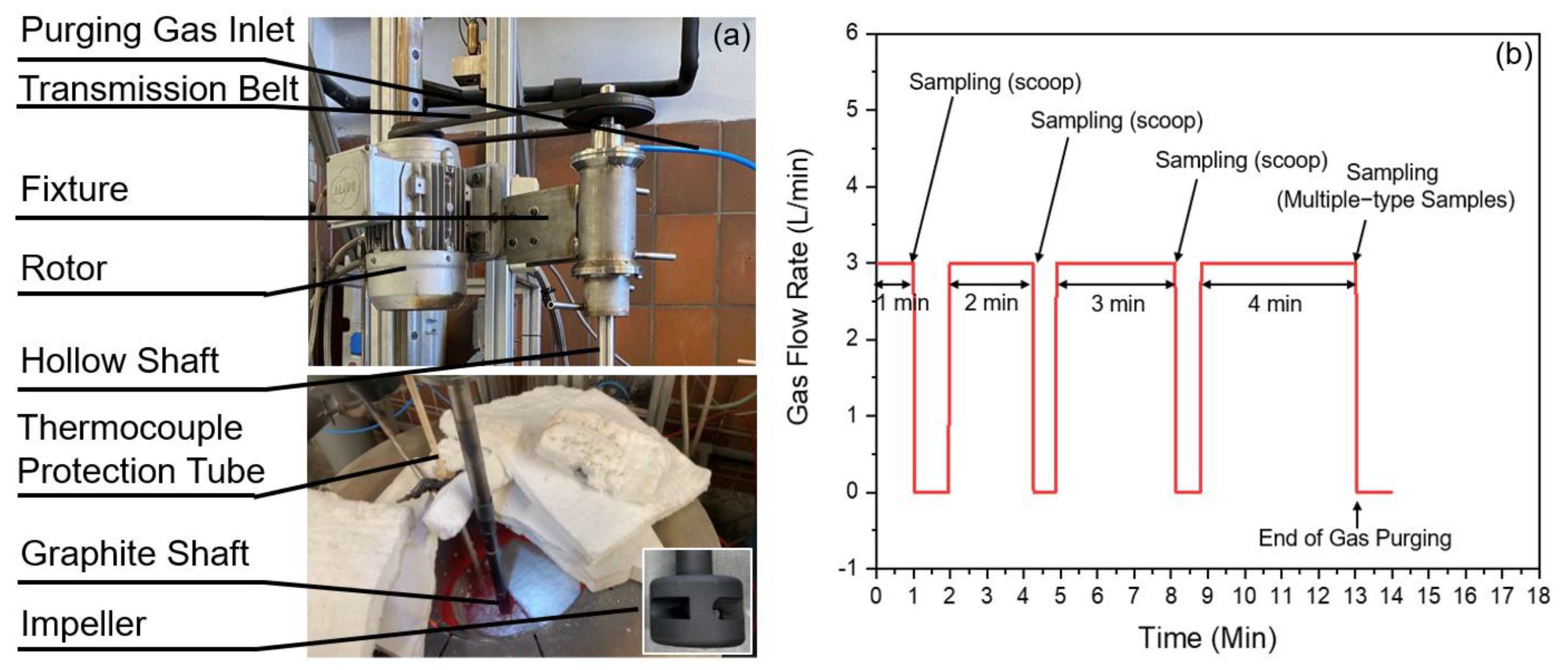
2.1. Set-Up and Materials

TiB2′s separation behavior during the degassing process was studied using a 5 kg floatation tank built in the Institute for Process Metallurgy and Metal Recycling (IME) at RWTH Aachen University.
The degassing unit is shown in Figure 1a. The upper part of the unit consists of a transmission belt, fixture, and rotor. The lower part of the unit was connected to the upper part through a steel hollow shaft. The steel shaft was connected to a graphite shaft (diameter 24 mm), at the bottom of which a graphite impeller (diameter 40 mm) was screwed in. The geometry of the impeller was a downsized version of a typical commercial impeller. The rotation speed and vertical location of the impeller was adjustable via, respectively, a rotor and a hydraulic system. Gas was supplied through an inlet in the upper fixture of the unit. The flow rate was controlled via an external digital system. Figure 1b shows as an example the flow rate history monitored with the digital system.

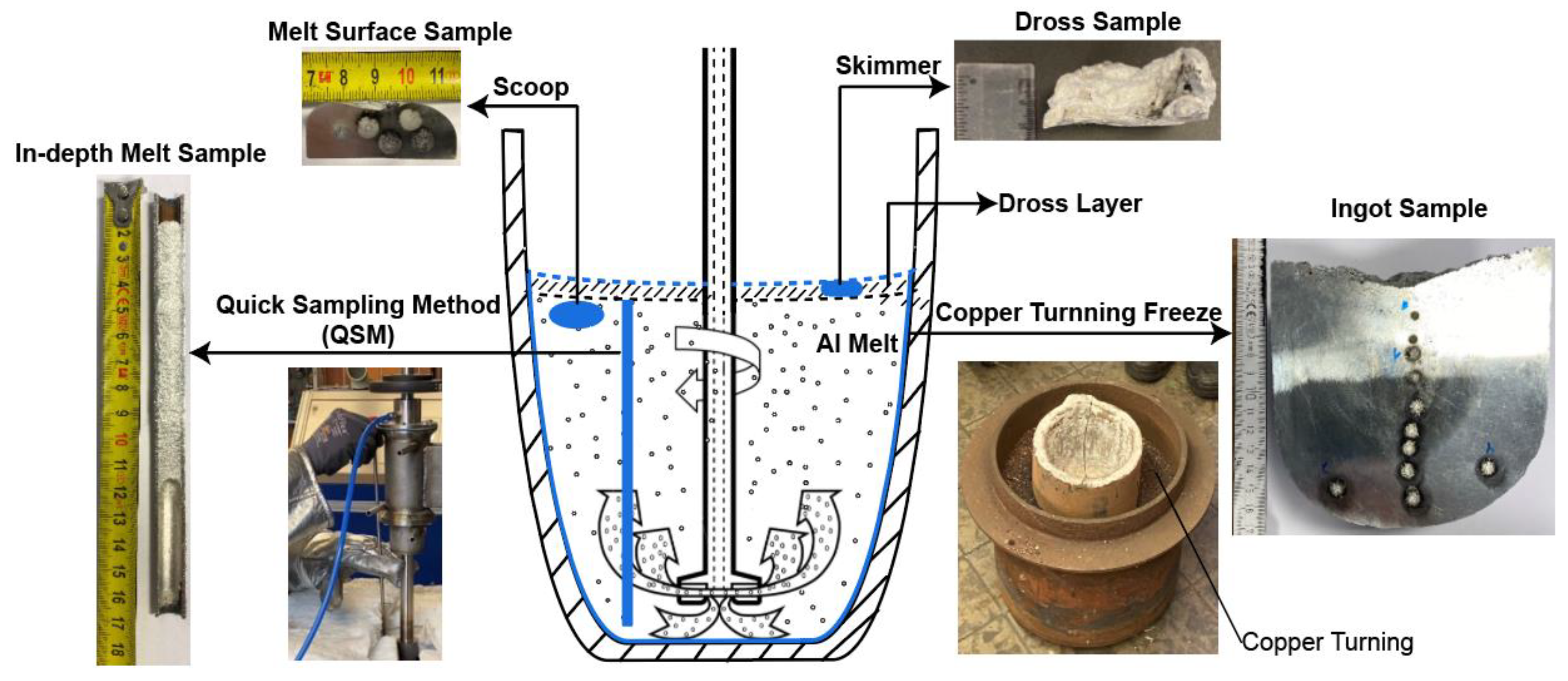
2.2. Trial Procedures

The base melt was prepared by remelting 4.7 kg 5083 ingots (representative composition given in Table 2) in an SC-50 clay–graphite crucible (Aug. Gundlach KG, Großalmerode, Germany) placed inside a resistance heated furnace (Thermo-Star GmbH, Aachen, Germany). The crucible was with a net height of 160 mm, a net upper diameter of 151 mm, and a net lower diameter of 94 mm. After a liquid alloy was obtained and the melt temperature reached 730 °C, a 3 min melt prior to degassing treatment was performed to clean the melt. The prior treatment was conducted at a rotor speed of 550 rounds per minute (rpm) and at an argon (Ar, 5N) flow rate of 3 L/min. Following the prior treatment, the dross formed on the melt surface was skimmed and 0.3 wt. % Al-5Ti-1B in coil form was added into the melt. Immediately after TiB2 introduction, the degassing treatment was launched by submerging again the same impeller into the melt and meanwhile admitting Ar gas flow. Trials with 3 different impeller rotary speeds, namely 400 rpm, 550 rpm, and 700 rpm, were performed at a gas flow rate of 3 L/min. The submergence of the impeller was 2/3 of the melt depth. Detailed trial parameters are tabulated in Table 3. Each trial was repeated 3 times.
The overall time of the degassing treatment was set to 10 min. Upon, respectively, 1, 3, 6, and 10 min (net time) of degassing treatment, the impeller rotation and gas supply were shortly interrupted to allow for a rapid melt surface sampling action via a BN-coated metallurgical scoop. The timing of the sampling was imposed on the gas flow rate history, which is plotted in Figure 1b. The scoop sampling (i.e., melt surface sampling) region was located beneath the dross layer, as is schematically shown in Figure 2.
Particularly for the F-5kg-TB-400 and F-5kg-TB-700 trials, upon completion of degassing, i.e., 10 min net time of gas purging, the quick sampling method (QSM) was applied to map the TiB2 particles’ distribution along the melt-depth direction. For the sake of simplicity, this sample is named the in-depth melt sample. A detailed introduction to the QSM technique and its principle can be found in [20]. Following the QSM operation, ca. 20 g of the dross sample was collected via a skimmer from the top of the melt. Finally, the remaining melt was taken out of the furnace together with the crucible and frozen within a metal tank filled with fine copper turnings (Figure 2). The locations from which the in-depth melt sample, dross sample, and ingot sample were taken are schematically shown in Figure 2. This figure also gives snapshots of the samples taken via different approaches. It is worth mentioning that the reason for taking dross and ingot samples in addition to the in-depth melt sample was to obtain information on the TiB2 particles at the very top and bottom of the melt, since the QSM has the disadvantage of not being able to capture inclusion information from the dross layer of the melt and the bottom layer of the melt.

2.3. TiB2 Evaluation

The melt surface samples, in-depth melt samples, and frozen ingot samples were sectioned and prepared by successively grinding them using grade 300 emery paper, and then ultrasonically cleaned and dried under warm air. Following sample preparation, Spark Spectrometer analysis was conducted with a focus on the boron (B) element. The analyzed region of the in-depth melt samples and frozen ingot samples distributed along the melt-depth direction.
The dross samples were drilled and the drillings were used for ICP-OES analysis.
The B content [ppm] measured via either a spectrometer or ICP-OES analysis was translated to TiB2 [ppm] using a simple relation assuming all boron (B) is present as TiB2 in the melt [21]:
w T i B 2 = 3.18   w B

3. Results

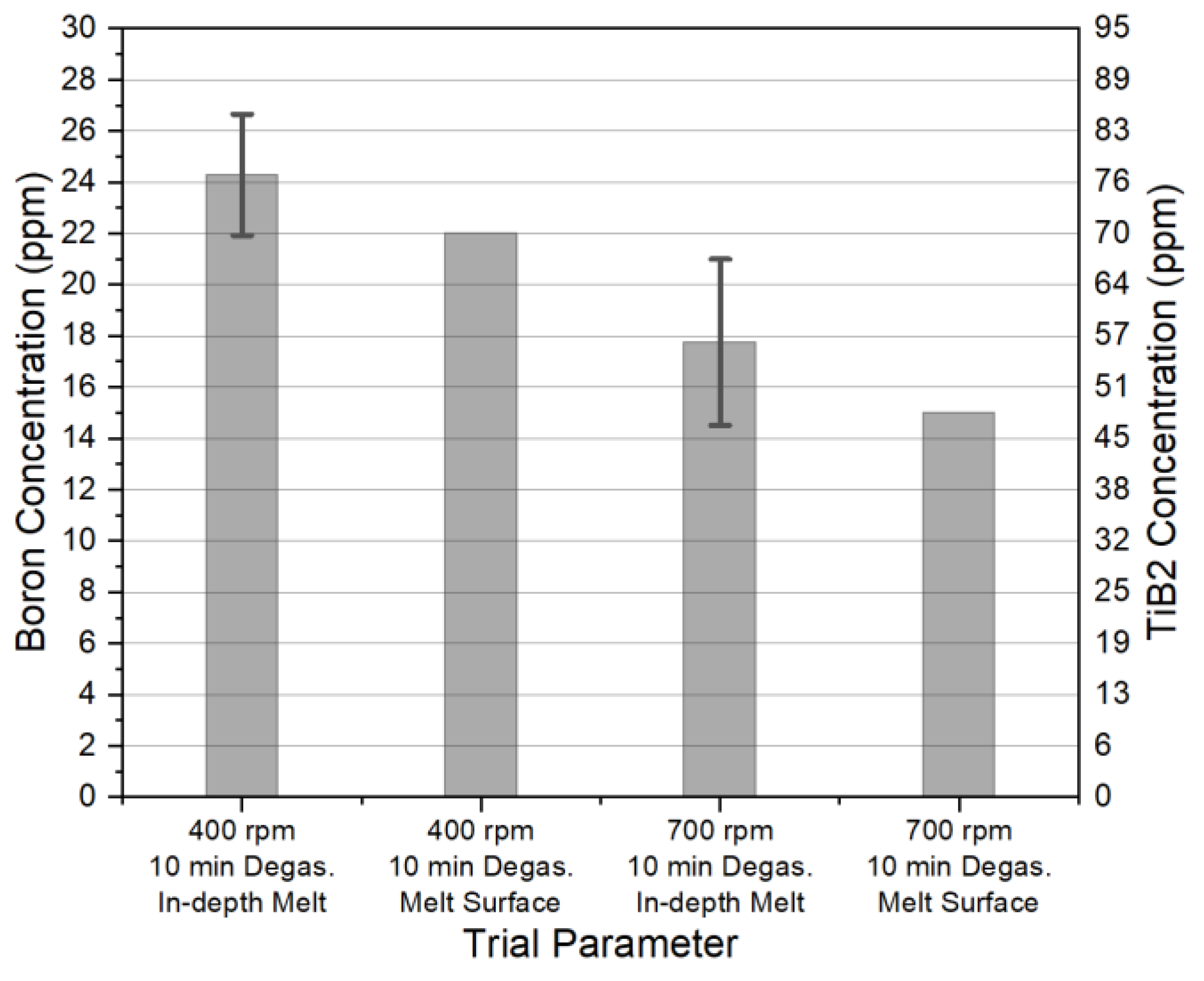
3.1. TiB2 Distribution

The boron (B) content distribution (equivalent to the TiB2 distribution) along the melt-depth direction (including the dross region) after 10 min of degassing treatment is shown in Figure 3. The samples analyzed were taken from melt degassed at 400 rpm (Figure 3a) and 700 rpm (Figure 3b) impeller rotary speeds, respectively. The data points in the main section of the line were obtained through analyzing the in-depth melt samples, whilst the data points at the two ends of the line were obtained from analyses of the dross and ingot samples.
It can be seen from Figure 3a,b that after 10 min of degassing, TiB2 particles were separated to the dross layer irrespective of the impeller rotary speed. Correspondingly, the TiB2 concentration in the main section of the melt was lower than the initial boron concentration (the initial boron content is given as a theoretical value calculated by extrapolating the change in TiB2 concentration as a function of time using the data which will be presented in the upcoming section). Sedimentation of TiB2, however, was not suggested. As is evident in Figure 3a,b, even at the bottom of the melt, the TiB2 concentration was not significantly different from main section of the melt. Our results support the findings of Gu et al. [18] and Khorasani [17]: both of their studies observed the TiB2 removal phenomenon during Al melt degassing treatments.

3.2. Influence of Impeller Rotation Speed on TiB2 Removal Kinetics

We can see in Figure 3 that after 10 min of gas-purging treatment, the TiB2 particles’ distribution along the melt-depth direction was relatively homogeneous. This can be attributed to the forced convection of the melt induced by mechanical agitation and simultaneous bubbling. From this perspective, to measure the TiB2 content representing approximately the TiB2 content of the entire volume of the melt, it may be sufficient to analyze the melt surface sample, which was taken from beneath dross layer. This inference is validated by comparing the B analytical results from both the melt surface sample and the QSM sample (i.e., the in-depth melt sample). A benchmarked comparison is shown in Figure 4. The samples employed are from the 10 min degassed melt, corresponding to the F-5kg-TB-400 and F-5kg-TB-700 trials. It can be seen from the figure that the B content analyzed from the melt surface sample, when compared with the B analyzed from the in-depth melt sample, is on average 10% lower. Nevertheless, the former value lies within the deviation of the latter value, indicating the soundness of using B values from the melt surface (beneath the dross layer) to represent B values averaged from different depth levels of the melt.
The impact of the impeller rotary speed on the TiB2 separation rate was investigated using samples taken from the melt surface. Three different impeller rotary speeds, namely 400, 550, and 700 rpm, were assessed and these results are shown, respectively, in Figure 5a–c. In all of the three groups of trials, the TiB2 concentration in the melt decayed over time. With the increase in rotary speed from 400 to 700 rpm, the reduction rate of the B content in the melt increased from 1.35 ppm/min to 1.74 ppm/min.
The data shown in Figure 5a–c are fit exponentially. The fitting curves, formulas, and associated R2 coefficients are given in the relevant figure. Each of the R2 values suggests a good fit of the data to the regression model. For each rotary speed, the initial B content (B content at 0 min treatment) obtained through fitting were similar, varying from 32 to 34 ppm. The results indicate that 2–4 ppm of B remained in the melt after the prior melt-cleaning treatment. At highest rotary speed, i.e., 700 rpm, around 67 wt. % TiB2 particles were removed after 10 min of degassing treatment. The corresponding removal rate constant of TiB2 particles is 0.08 min−1, as is indicated by the exponential coefficient in front of × (the time variable) in Figure 5c.
Qualitatively, the exponential decrease in TiB2 concentration in the melt shown in Figure 5a–c can be interpreted according to the conventional deterministic flotation model. According to this model, the velocity at which bubbles ascend is perfectly known and the collision frequency at which bubbles collect the particles is directly correlated to the volume of the fluid swept up by the bubbles and the velocity at which the bubbles ascend. Both parameters are decided by the gas flow rate and the size of bubbles in the melt. Under the assumption of a uniform TiB2 particle size in the melt and a complete mixing regime, the deterministic flotation model can be described in a simplified way using the expressions below [22,23,24]:
w T i B 2 = w T i B 2 ( 0 ) e k f t
k f = 3 2 G A t d b E c
E c = 3 d p d b
where wTiB2 [ppm] is the mass fraction of TiB2 particles in the melt, wTiB2(0) is the initial mass fraction of TiB2 in the melt, and t [s] is the elapsed time of the degassing process. kf [min−1] is the inclusion flotation rate constant, whose value depends on operational parameters such as the rotary speed and gas flow rate (kf [min−1] is a kinetic separation factor. When multiplying kf [min−1] with the particle number/number density/mass fraction in the melt, one obtains the rate at which the particles are removed, e.g., #/min, ppm/min. When timed with the degassing time t [min], the exponential function of kft, i.e., exp(−kft), gives the ratio of the remained particles/particle density/mass fraction to the initial particles/particle density/mass fraction in the melt.) G [L/min] is the gas flow rate, At [mm2] is a cross-sectional area of the degassing tank, db [mm] and dp [μm] are, respectively, the bubble and particle sizes, and Ec [unitless] is the collision efficiency. As the rotary speed was suggested to have a positive impact on db [25,26], the conventional deterministic flotation model represented by Equations (2)–(4) can explain qualitatively the positive relationship between the rotary speed and the removal kinetics of TiB2, which was suggested in Figure 5a–c.
We are more interested in a quantitative evaluation of the conventional deterministic flotation model. So far, a comparison of the experimental data with the deterministic flotation model is rarely found in the context of aluminum melt. Under appropriate assumptions of the TiB2 particle and bubble size [26,27,28], an evaluation of the analytical deterministic flotation model is made and the results are listed in Table 4. By comparing the kf values listed in Table 4 with the removal rate constant of TiB2 given in Figure 5a–c, it can be seen that the conventional flotation model estimates the inclusion removal rate constant to be ca. 10 times lower. The discrepancy between the model predictions and experimental data may even be greater should the real bubble size in our degassing unit be substituted in the expression of the model, as the real bubble size in our degassing unit is supposed to be bigger than the bubble size given in Table 4. Another contrasting piece of evidence concerning the applicability of the conventional deterministic flotation model in predicting the TiB2 removal rate was found by Khorasani and Schaffer et al. [16,17]. These authors reported that increasing the gas flow rate has no significant impact on the TiB2 removal rate. Such results do not support Equations (2)–(4) either, which suggests that the inclusion removal rate is strongly dependent on the gas flow rate.
Combining the results from the literature and our experimental observations, it is indicated that there are other mechanisms which play a more dominant role in TiB2 removal during degassing process, and such mechanisms may not be related to bubble flotation mechanisms. One of the mechanisms worth noting was proposed by Khorasani [17]. This author mentioned shortly that during degassing, TiB2 particles were brought to the dross layer through the bulk melt recirculation and trapped there. In the following paragraph, we provide a more complete description of this mechanism, which is yet to be provided by Khorasani. We name this mechanism the entrainment–entrapment (EE) mechanism, and a schematic illustration of the model is given in Figure 6. Note that this illustration also includes the contribution of the conventional flotation mechanism, despite it not being deemed as a major mechanism.
The word entrainment stems from the mechanical entrainment model (termed also the turbulent entrainment model) in froth flotation disciplines [23,29]. The model states that the fine particles enter the froth layer from the region below the froth–pulp interface. The main driven impetus is the melt turbulence below the froth layer. Such a “froth” layer, being in our study the dross layer, is composed of mainly bubbles, oxide films, and other inclusions. During degassing, the intense turbulence renders the melt a high velocity at the melt–dross interface, through which particles experience a high drag force and their entrainment is promoted. Once entering the dross layer, the TiB2 particles have a high chance of colliding and agglomerating with densely packed oxide films and hence being entrapped. At the interface between the dross layer and the aluminum melt, TiB2 particles may also be adhered directly to suspended oxide films due to turbulence velocity fluctuations. One may envision the oxide films constituting a discontinuous rough surface which can effectively collect TiB2 particles.
Analogous to conventional flotation models, the above EE mechanism is able to explain the exponential decay of TiB2 particles and rotary-speed-dependent TiB2 removal rate. The biggest difference between the EE mechanism and the conventional flotation model is the dependence on bubbles for the transportation of TiB2 particles into the dross layer. The role of gas bubbles in the EE mechanism is limited to affect the turbulence and hence only has an indirect influence on the rate at which TiB2 particles are transported to the dross layer.

4. Conclusions

In the present work, the separation behavior of TiB2 during the degassing process of a 5083 alloy was studied and the findings are summarized as follows:
  • Particle mapping results suggest that during degassing, TiB2 particles are separated to the dross layer, while their concentration in main part of the melt is relatively homogeneous.
  • A significant removal of TiB2 particles during the Cl2-free degassing process was confirmed. The removal rate of TiB2 particles increased with the impeller rotary speed. At 700 rpm, the removal rate constant of TiB2 particles was 0.08 min−1.
  • Conventional deterministic flotation model estimates of the inclusion removal rate constant is ca. 10 times lower compared with the experimental results. The EE mechanism is believed to be responsible for TiB2 removal during the Cl2-free degassing process. Instead of bubbles, the EE mechanism considers mainly the contribution of melt turbulence and the hetero-agglomeration of TiB2 and OF to the removal effect.
  • From the point of view of preventing the fade of TiB2, it is suggested to add an Al-Ti-B grain refiner at the end phase of batch degassing treatments or after in-liner degassing. Reducing the impeller rotary speed or shortening the degassing treatment time (for in-line degassers, the time refers to the residence time) can also help; nevertheless, one needs to consider if the adjusted process is able to remove other harmful dissolved impurities and inclusions sufficiently.
  • To validate the EE mechanism proposed to be accountable for TiB2 removal during Cl2-free degassing treatments, more theoretical and experimental work is required. The establishment of an analytical model deserves fundamental attention for predicting TiB2 removal during Cl2-free degassing treatments. From an experimental perspective, it is necessary to assess the influence of the dross layer’s properties on TiB2 removal efficiency. Be it wet or dry, or containing oxide films or other types of inclusions, it will be interesting to know how the dross layer affects the TiB2 separation behavior in the corresponding melt.

Author Contributions

Conceptualization, C.L., W.S. and B.F.; methodology, C.L., W.S., M.G. and B.F.; validation, C.L., M.G., W.S. and B.F.; formal analysis, C.L.; investigation, C.L., M.G., W.S. and B.F.; writing—original draft preparation, C.L.; writing—review and editing, C.L., M.G., W.S. and B.F.; supervision, M.G. and B.F.; project administration, C.L. and B.F.; funding acquisition, B.F. All authors have read and agreed to the published version of the manuscript.

Funding

This research was funded by the “Project 4 Continuation (P4C)” within the Advanced Metals and Process (AMAP) Open Innovation Research Cluster at RWTH, Aachen University, Germany. The project members are Constellium, Magma, Nemak, Novelis, Speira, Trimet, and Vesuvius.

Data Availability Statement

The raw data supporting the conclusions of this article will be made available by the authors on request.

Acknowledgments

Special thanks are addressed to the China Scholarship Council (CSC) for the financial support of Cong Li.

Conflicts of Interest

Author Wolfram Stets was employed by the company Foseco Nederland BV. The remaining authors declare that the research was conducted in the absence of any commercial or financial relationships that could be construed as a potential conflict of interest.

References

  1. Whitehead, A.J.; Copper, P.S.; McCarthy, R.W. An Evaluation of Metal Cleanliness and Grain Refinement of 5182 Aluminum Alloy DC Cast Ingot Using Al-3% Ti-0.15%C and Al-3%Ti-1%B Grain Refiners. In Proceedings of the Light Metals; The Minerals, Metals & Materials Society, San Diego, CA, USA, 28 February–4 March 1999; pp. 763–772. [Google Scholar]
  2. EL Haj, B.A.; Hamadellah, A.; Bouayad, A.; El Akili, C. Review of Grain Refinement Performance of Aluminium Cast Alloys. Metall. Mater. Eng. 2023, 29, 1–15. [Google Scholar] [CrossRef]
  3. Liu, S.; Zhao, T.; Fu, J.; Zu, Q. Development of Inoculants for Aluminum Alloy: A Review. Materials 2023, 16, 5500. [Google Scholar] [CrossRef] [PubMed]
  4. Milani, V.; Timelli, G. Solid Salt Fluxes for Molten Aluminum Processing—A Review. Metals 2023, 13, 832. [Google Scholar] [CrossRef]
  5. Dion-Martin, O.; Desmeules, J.-F.; Dumont, R. Molten Aluminium Transfer: Review and Comparison of Different Technologies. In Proceedings of the Light Metals; The Minerals, Metals & Materials Society, Virtual, 15–18 March 2021; pp. 769–777. [Google Scholar]
  6. Rathinasuriyan, C.; Karthik, K.; Sridhar, K. Investigation of Degassing on Aluminum Alloy by Rotatory Impeller Degasser. Mater. Today Proc. 2023, in press. [Google Scholar] [CrossRef]
  7. Samaha, S.; Robichaud, P.; Gauthier, P.; Colbert, J.; Wang, T.; Hammersmith, G.; Event, P.; Maltais, B. Chlorine Free Degas System for Aluminium Slab Casting and Its Effect on Sheet Products. In Proceedings of the Light Metals; The Minerals, Metals & Materials Society, Anaheim, CA, USA, 27 February–3 March 2022; pp. 655–665. [Google Scholar]
  8. Liu, G.; Ren, Y.; Ma, W.; Morita, K.; Lei, Y.; Zhan, S.; Lv, G.; Li, S.; Wang, Z.; Li, R. Recent Advances and Future Trend of Aluminum Alloy Melt Purification: A Review. J. Mater. Res. Technol. 2024, 28, 4647–4662. [Google Scholar] [CrossRef]
  9. Wu, J.; Djavanroodi, F.; Gode, C.; Attarilar, S.; Ebrahimi, M. Melt Refining and Purification Processes in Al Alloys: A Comprehensive Study. Mater. Res. Express 2022, 9, 032001. [Google Scholar] [CrossRef]
  10. Raabe, D.; Ponge, D.; Uggowitzer, P.J.; Roscher, M.; Paolantonio, M.; Liu, C.; Antrekowitsch, H.; Kozeschnik, E.; Seidmann, D.; Gault, B.; et al. Making Sustainable Aluminum by Recycling Scrap: The Science of “Dirty” Alloys. Prog. Mater. Sci. 2022, 128, 100947. [Google Scholar] [CrossRef]
  11. Snow, G.; Pattle, D.; Walker, G.R.D.U. An Efficient Degassing System for the Aluminium Cast House. In Proceedings of the Light Metals; The Minerals, Metals & Materials Society, Denver, CO, USA, 24–26 February 1987; pp. 717–727. [Google Scholar]
  12. Socha, L.; Prášil, T.; Gryc, K.; Svizelova, J.; Saternus, M.; Merder, T.; Pieprzyca, J.; Nuska, P. Assessment of Refining Efficiency during the Refining Cycle in a Foundry Degassing Unit in Industrial Conditions. Sci. Rep. 2024, 14, 1415. [Google Scholar] [CrossRef] [PubMed]
  13. Jang, H.S.; Kang, H.J.; Lee, G.H.; Yoon, P.H.; Park, J.Y.; Choi, Y.S.; Shin, S. Effect of Gas Bubbling Filtration Treatment Conditions on Melt Quality of Alsimgcu Alloy. Metals 2021, 11, 841. [Google Scholar] [CrossRef]
  14. Sigworth, G.K.; Williams, E.M.; Chesonis, D.C. Gas Fluxing of Molten Aluminum: An Overview. In Essential Readings in Light Metals: Cast Shop for Aluminum Production; Springer: Cham, Switherland, 2013; ISBN 978-3-319-48574-4. [Google Scholar]
  15. Simensen, C.J. The Effect of Melt Refining upon Inclusions in Aluminum. Metall. Trans. B 1982, 13, 31–34. [Google Scholar] [CrossRef]
  16. Schaffer, P.L.; Dahle, A.K. The Effect of Degassing on Grain Refinement in Commercial Purity Aluminum. Metall. Mater. Trans. A Phys. Metall. Mater. Sci. 2009, 40, 481–485. [Google Scholar] [CrossRef]
  17. Khorasani, A.N. Effect of Degassing on Aluminium Silicon Alloys. AFS Trans. 1995, 103, 515–519. [Google Scholar]
  18. Gu, H.; Zou, Y.Z.; Bin Xu, Z.; Zeng, J.M. Investigation on Purification and Degassing of TiB2/Al Composite Fabricated by LSM Method. Key Eng. Mater. 2007, 353–358, 3051–3054. [Google Scholar] [CrossRef]
  19. Gudmundsson, T.; Saevarsdottir, G.; Sigfusson, T.I.; Mccartney, D.G. Chlorination of TiB2 Grain Refined Aluminium Melts. In Proceedings of the Light Metals; The Minerals, Metals & Materials Society, Orlando, FL, USA, 9–13 February 1997; pp. 851–855. [Google Scholar]
  20. Li, C.; Zhang, X.; Gökelma, M.; Stets, W.; Friedrich, B. A Quick Sampling Method for Mapping Particle Distribution in Al-Melt. In Proceedings of the European Metallurgical Conference, Düsseldorf, Germany, 23–26 June 2019; pp. 35–50. [Google Scholar]
  21. Quested, T.E. Understanding Mechanisms of Grain Refinement of Aluminium Alloys by Inoculation. Mater. Sci. Technol. 2004, 20, 1357–1369. [Google Scholar] [CrossRef]
  22. Engh, T.A.; Sigworth, G.K.; Kvithyld, A. Principles of Metal Refining and Recycling; Oxford University Press: Oxford, UK, 2021; ISBN 978-0-19-881192-3. [Google Scholar]
  23. Wang, D.; Liu, Q. Hydrodynamics of Froth Flotation and Its Effects on Fine and Ultrafine Mineral Particle Flotation: A Literature Review. Miner. Eng. 2021, 173, 107220. [Google Scholar] [CrossRef]
  24. Dai, Z.; Fornasiero, D.; Ralston, J. Particle-Bubble Collision Models—A Review. Adv. Colloid Interface Sci. 2000, 85, 231–256. [Google Scholar] [CrossRef] [PubMed]
  25. Garcia-Ochoa, F.; Gomez, E. Theoretical Prediction of Gas-Liquid Mass Transfer Coefficient, Specific Area and Hold-up in Sparged Stirred Tanks. Chem. Eng. Sci. 2004, 59, 2489–2501. [Google Scholar] [CrossRef]
  26. Johansen, S.T.; Gradahl, S.; Grontvedt, P.O.; Tetlie, P.; Gammelsæter, R.; Venas, K.; Skaret, P.; Myrboastad, E.; Rasch, B. The Bubble Size and Mass Transfer Mechanisms in Rotor Stirred Reactors. In Proceedings of the Light Metals; The Minerals, Metals & Materials Society, Orlando, FL, USA, 9–13 February 1997; pp. 663–666. [Google Scholar]
  27. Johansen, S.T.; Graadahl, S.; Tetlie, P.; Rasch, B.; Myrboastad, E. Can Rotor-Based Refining Units Be Developed and Optimised on Water Model Experiment? In Proceedings of the Light Metals; The Minerals, Metals & Materials Society, San Antonio, TX, USA, 15–19 February 1998; pp. 805–810. [Google Scholar]
  28. Li, C.; Gökelma, M.; Dang, T.; Huang, J.; Huang, C.; Li, J.; Friedrich, B. Assessment of Melt Cleanliness of Secondary 5000 Aluminum Alloy via Non-Metallic Inclusions Characterization. Metall. Mater. Trans. B Process Metall. Mater. Process. Sci. 2023, 54, 578–592. [Google Scholar] [CrossRef]
  29. George, P.; Nguyen, A.V.; Jameson, G.J. Assessment of True Flotation and Entrainment in the Flotation of Submicron Particles by Fine Bubbles. Miner. Eng. 2004, 17, 847–853. [Google Scholar] [CrossRef]
Figure 1. (a) Degassing unit used for TiB2 separation trials; (b) the timing of taking samples during degassing trials for TiB2 analysis. Red line in (b) stands for gas flow rate.
Metals 14 00402 g001
Figure 2. Sampling approaches of degassing trials for studying TiB2 separation behavior.
Metals 14 00402 g002
Figure 3. Boron distribution along the melt–depth direction after 10 min of gas-purging treatment at different rotary speeds: (a) 400 rpm; (b) 700 rpm. Note that the 0 mm melt depth corresponds to the top of the dross region.
Metals 14 00402 g003
Figure 4. A benchmarked comparison of the boron content analyzed using the melt surface samples (beneath the dross layer) and in-depth melt samples.
Metals 14 00402 g004
Figure 5. Time-dependent B concentration variation in the melt during gas-purging treatment at different rotary speeds: (a) 400 rpm; (b) 550 rpm; (c) 700 rpm. Note that the fitting is made based on the B concentration variation. Red line represents the fitting curve.
Metals 14 00402 g005
Figure 6. Schematic of TiB2 removal mechanism during degassing process via entrainment–entrapment and bubble flotation.
Metals 14 00402 g006
Table 1. Compilation of results from the literature concerning TiB2 removal during degassing treatment [15,16,17,18,19].
ReferenceMethod of RefinementAlloyGasScaleRemovalProposed
Removal
Principle
Schaffer et al. [16]LanceCPAl 1Ar5 kgLimitedSedimentation
Khorasani [17]ImpellerA356-SrN2/Ar450 kgSignificantFloatation
Gu et al. [18]N.A.CPAl-5% TiB2C2Cl6N.A.SignificantFloatation
Gudmundsson et al. [19]ImpellerCPAl (with Na,K)Ar-5%Cl2130 kgLimited/
Simensen [15]Impeller (SNIF)CPAlN.A.Plant-scaleNegligible/
1: commercial pure aluminum.
Table 2. Chemical composition of the 5083 aluminum alloy.
5083Mg
(wt. %)
Si
(wt. %)
Ti
(wt. %)
Mn
(wt. %)
Al
(wt. %)
As-received4.720.060.040.52Balance
Table 3. Parameters of the degassing trials for studying TiB2 separation behavior.
/ Process WindowSampling Operations
Trial Nr.InclusionRotor Speed
(rpm)
Gas Flow Rate
(L/min)
Duration
(10 min)
ScoopDrossQSM 1Ingot
F-5kg-TB-400TiB2400310YesYesYesYes
F-5kg-TB-550TiB2550310YesNoNoNo
F-5kg-TB-700TiB2700310YesYesYesYes
1: quick sampling method [20].
Table 4. Evaluation of the conventional analytical deterministic flotation model.
ParameterGas Flow RateCross-Sectional
Area
Bubble
Diameter 1
Collision
Efficiency 2
Flotation
Rate Constant
SymbolGAtdbEckf
Unit(L/min)(m2)(mm)/(min−1)
Value30.011100.000160.0063
1: value set based on estimated bubble size in a pilot-scale degassers [26,27]; 2 assuming particle diameter dp = 0.54 μm [28].
Disclaimer/Publisher’s Note: The statements, opinions and data contained in all publications are solely those of the individual author(s) and contributor(s) and not of MDPI and/or the editor(s). MDPI and/or the editor(s) disclaim responsibility for any injury to people or property resulting from any ideas, methods, instructions or products referred to in the content.

