
Optimization of the Circular Channel Size and the A.C. Magnetic Field Parameters for Application in a Channel-Type Induction-Heating Tundish

Abstract
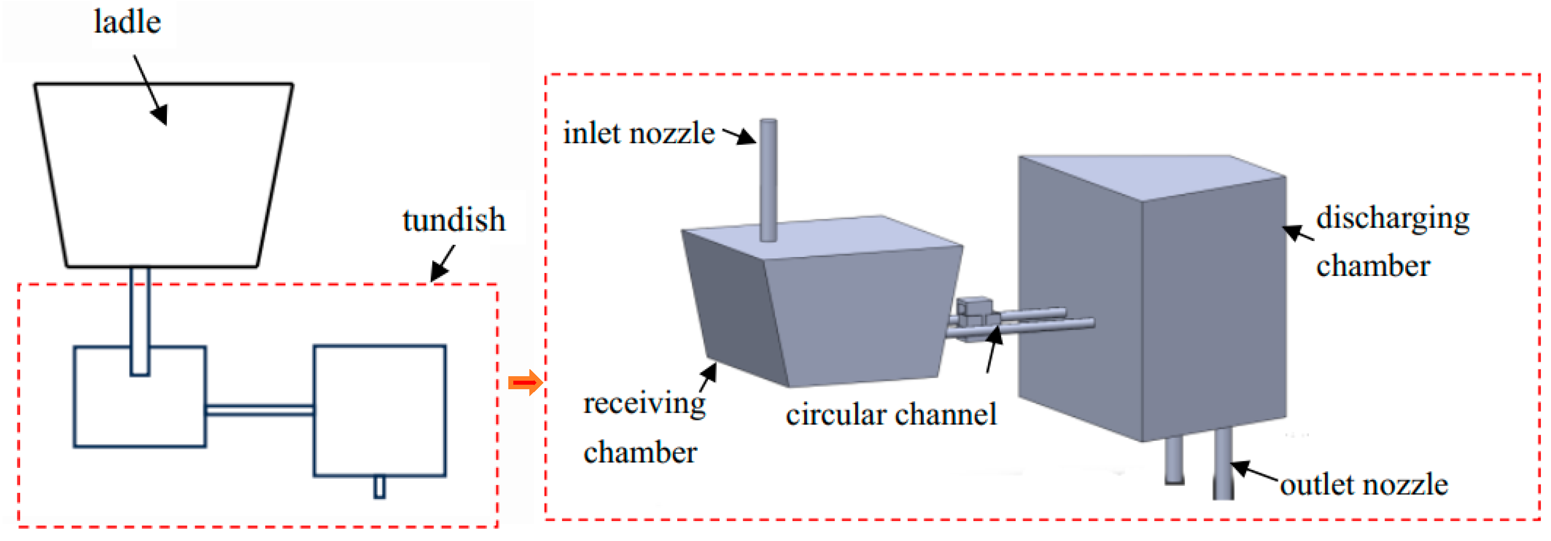
:1. Introduction
2. Mathematical Model
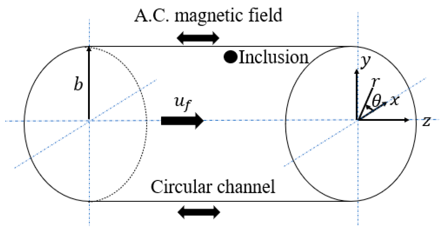
2.1. Removal of Inclusions in the Circular Channel
2.2. Heating up of Molten Steel in the Circular Channel
3. Discussion and Results
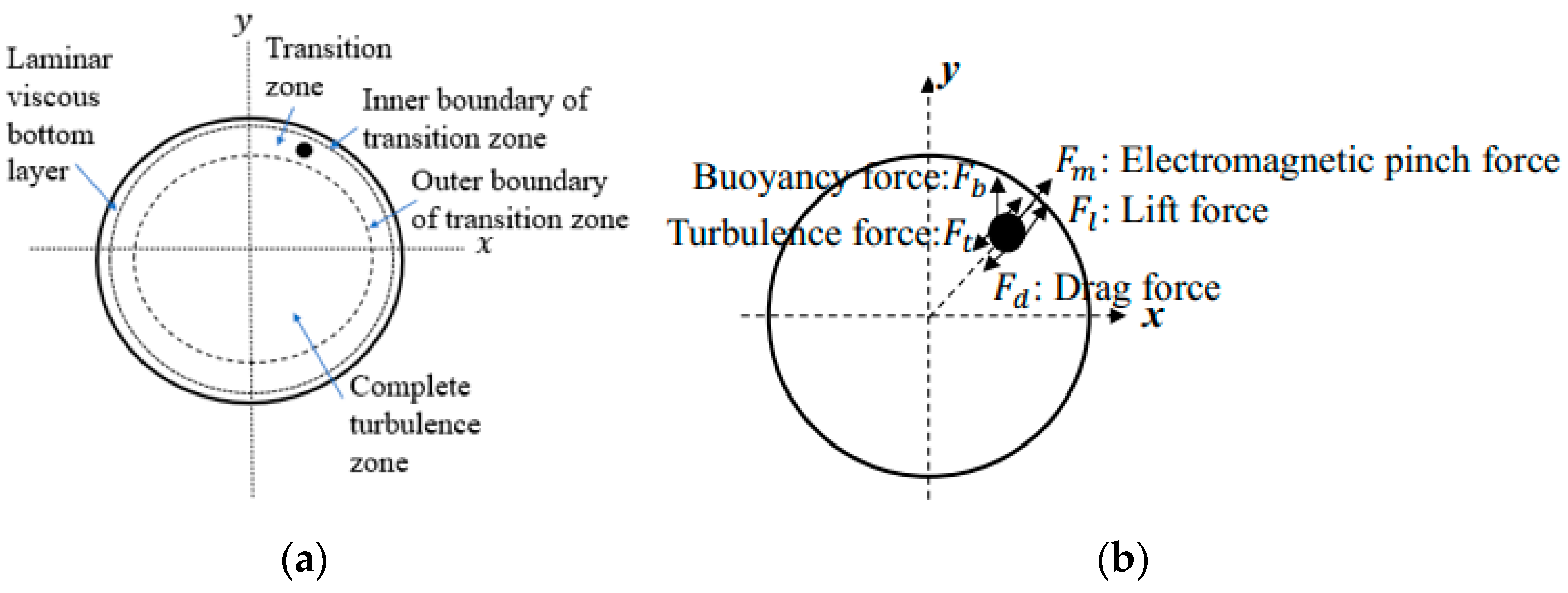
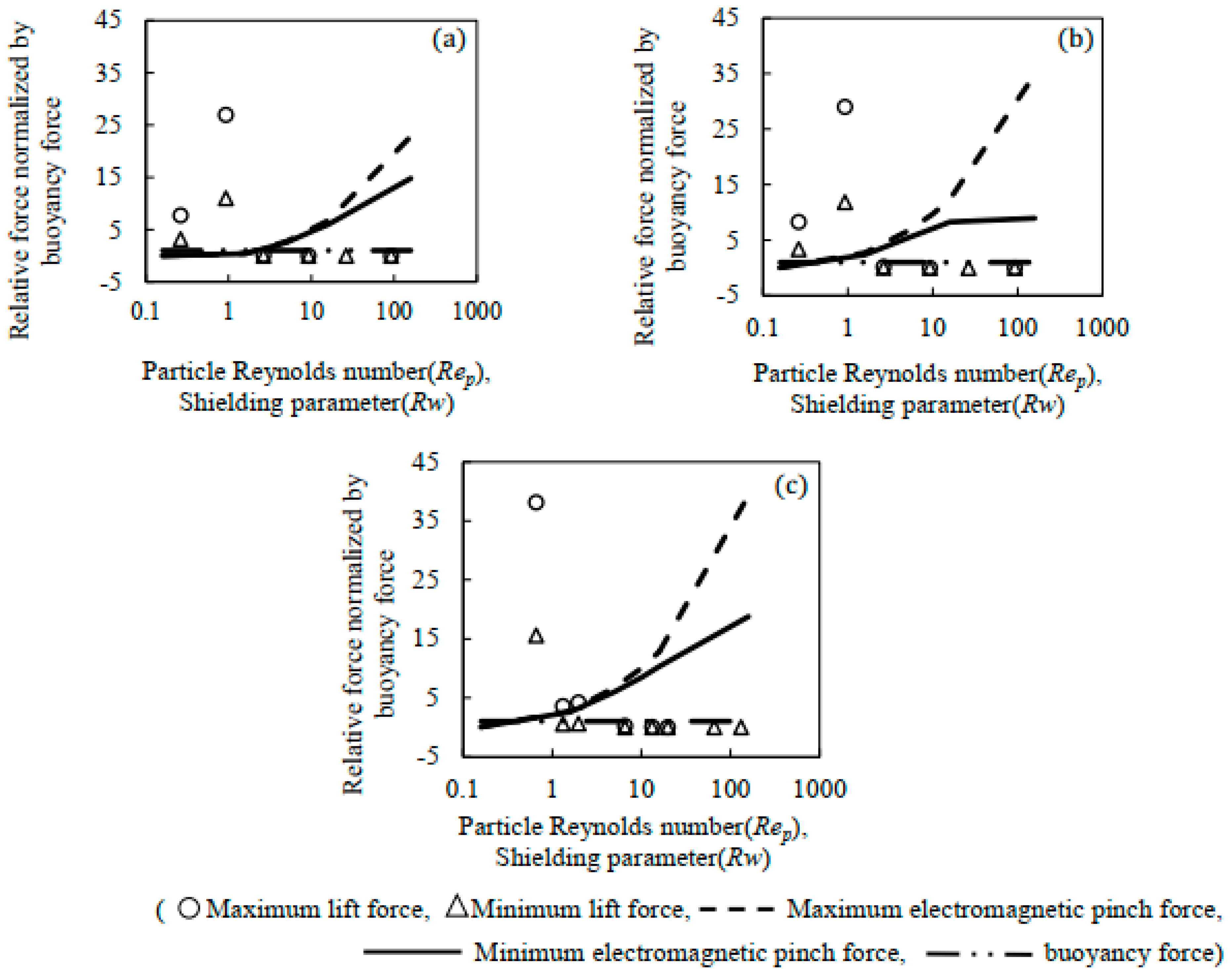
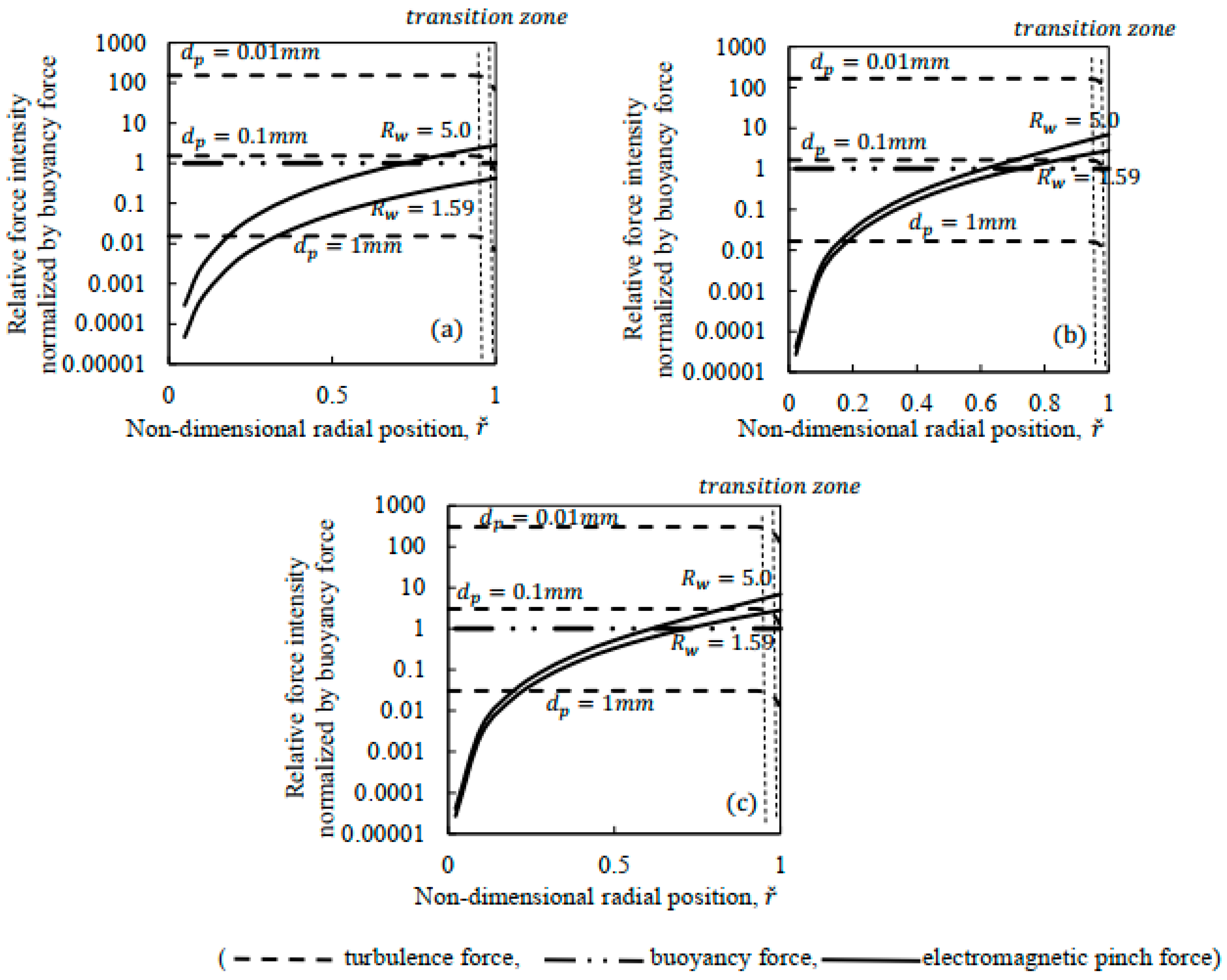
3.1. Forces Acting on an Inclusion in the Transition Zone Near the Channel Wall
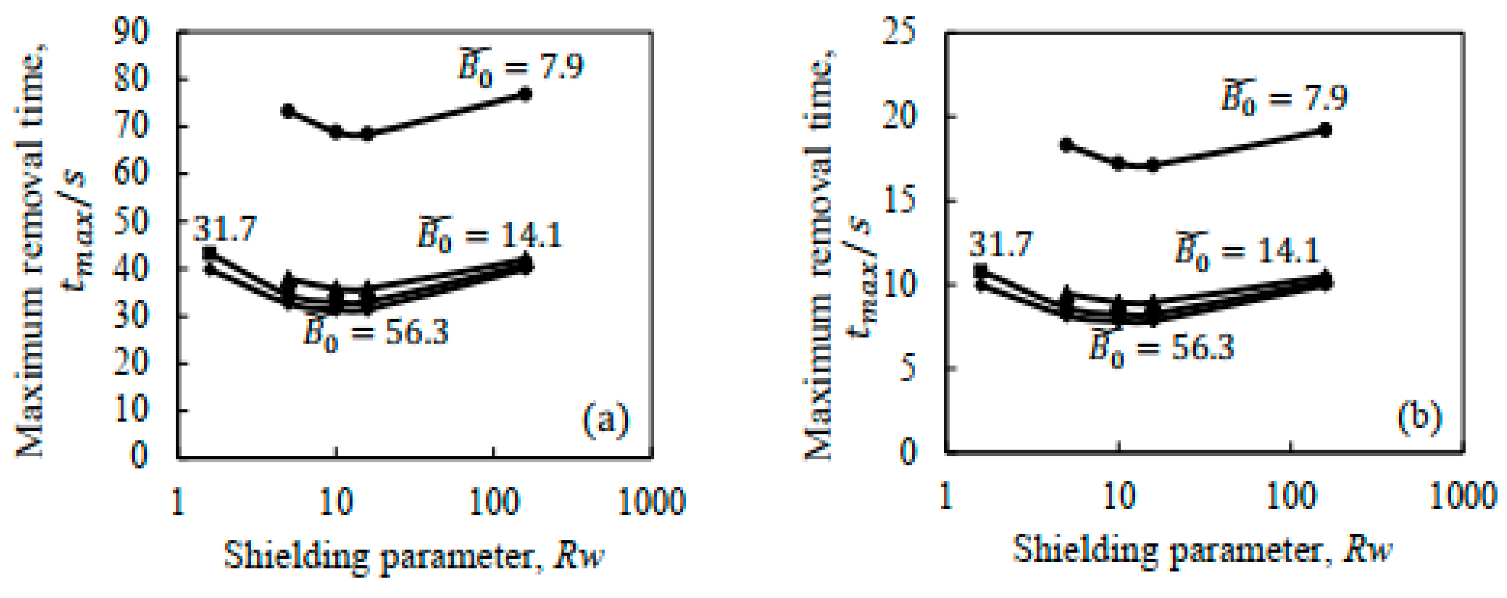
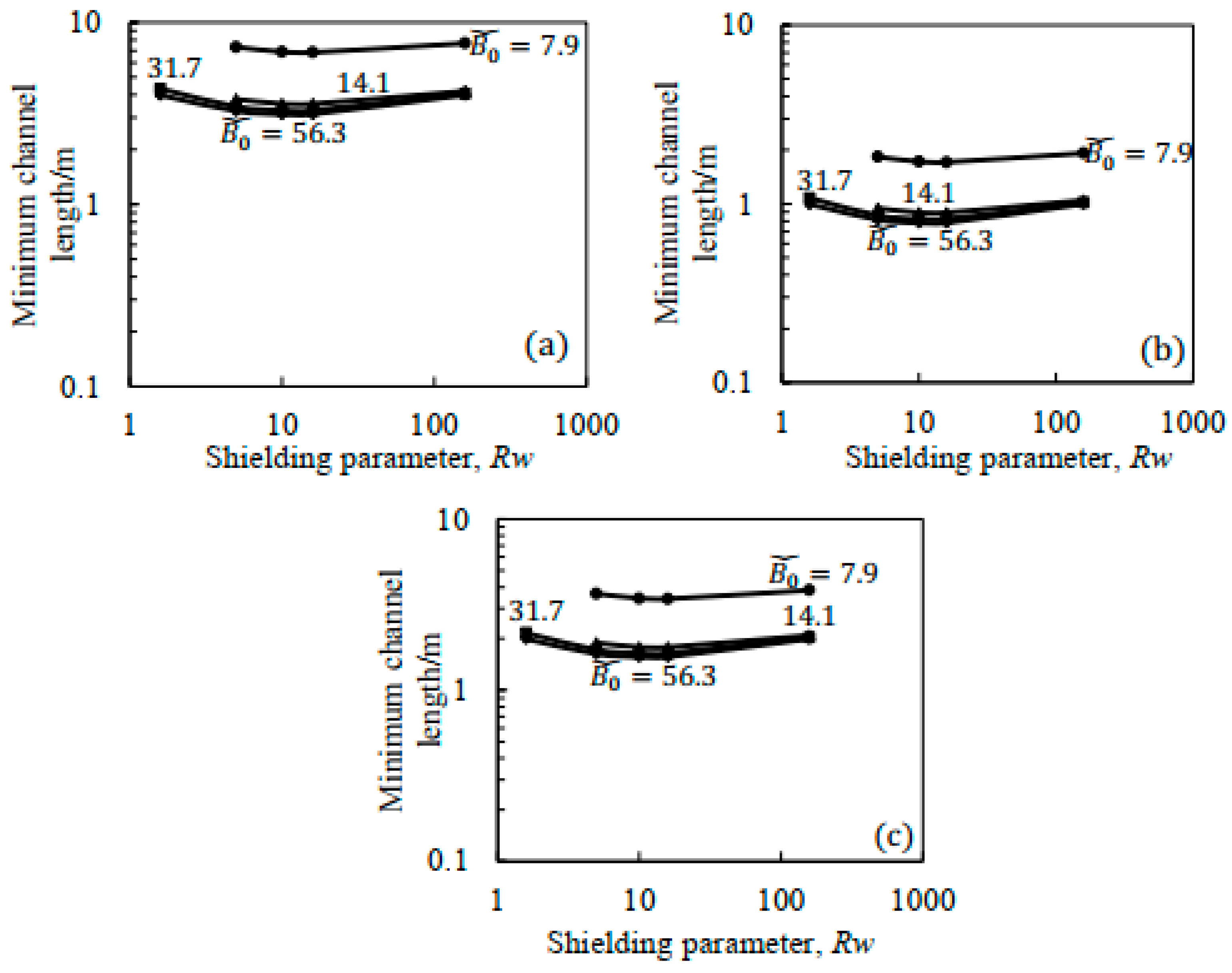
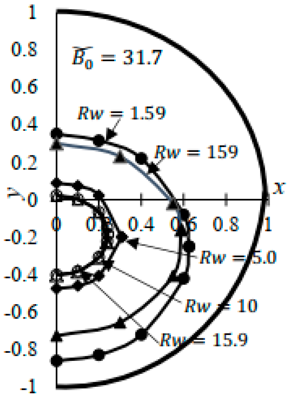
3.2. Removal of the Inclusions in the Circular Channel
3.3. Heating up of the Molten Steel in the Circular Channel
4. Conclusions
- (1)
- When the diameter of the inclusions is not less than 0.1 mm, the effect of the lift force and the turbulence force can be neglected under the calculation conditions in this paper, especially when the shielding parameter of the A.C. magnetic field is not less than 5.0;
- (2)
- The minimal channel length to remove the inclusions was calculated without the lift force and the turbulence force. When the shielding parameter of the A.C. magnetic field is 10.0~15.9, the minimal channel length is the shortest. Furthermore, the slow velocity of the molten steel is desirable. Under the condition of the A.C. magnetic field parameters and , the minimum channel length is about 1 m to remove the inclusion with the diameter of and it is about 4 m for the inclusion diameter of when the velocity of the molten steel is 0.1 m/s. The minimum channel length is about 2 m to remove the inclusion with the diameter of if the flow velocity of the molten steel is 0.2 m/s;
- (3)
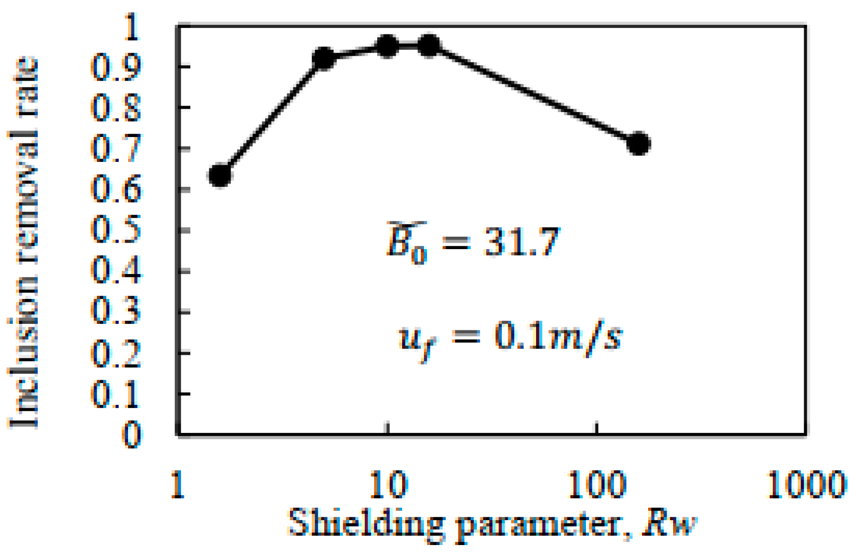
- For industrial applications, the removal rate of the 0.1 mm inclusions in a 1 m length channel was calculated. The A.C. magnetic field frequency is an important parameter for removing the inclusions and the shielding parameter of 10.0~15.9 is optimal. When the shielding parameter is 10.0 or 15.9, the removal rate of the inclusions in the channel can reach more than 95% while the removal rate of inclusions in the channel is only about 60% if the shielding parameter is 1.59;
- (4)
- For heating up the molten steel in the circular channel, a large shielding parameter, a large non-dimensional magnetic field intensity, and a slow velocity of the molten steel flow are suitable for reducing the channel length. If the length of the circular channel is 1 m and the flow velocity of the molten steel is 0.1 m/s, it is possible to increase the molten steel by 10 K under the A.C. magnetic field condition of ;
- (5)
- From the industrial viewpoint, when the flow velocity of the molten steel in the circular channel with the length of 1 m and the radius of 0.075 m is 0.1 m/s, the A.C. magnetic field’s shielding parameter of 15.9 is the optimal parameter to simultaneously remove the inclusions and heat up the molten steel in the circular channel. And when the non-dimensional magnetic field intensity of the A.C. magnetic field is , the removal rate of the 0.1 mm inclusion in the channel can reach more than 95% and the temperature of molten steel can be heated by over 10 K.
Author Contributions
Funding
Data Availability Statement
Conflicts of Interest
Abbreviations
| radius of circular channel (m) | |
| magnetic field intensity (T) | |
| non-dimensional magnetic field intensity (-) | |
| ,, , and | Kelvin functions |
| coefficient (-) | |
| lift coefficient (-) | |
| drag coefficient (-) | |
| heat capacity of molten steel (J/Kg.K) | |
| inclusion diameter () | |
| lift force acting on the inclusion (N) | |
| lift force per unit inclusion’s volume acting on the inclusion (N/m3) | |
| turbulence force acting on the inclusion (N) | |
| turbulence force per unit inclusion’s volume acting on the inclusion (N/m3) | |
| drag force per unit inclusion’s volume acting on the inclusion (N/m3) | |
| buoyancy force per unit inclusion’s volume acting on the inclusion (N/m3) | |
| electromagnetic force per unit inclusion’s volume acting on the inclusion (N/m3) | |
| frequency of the A.C. magnetic field (Hz) | |
| length of circular channel (m) | |
| heating rate per unit channel length (J/m.s) | |
| , | radial direction and circumferential direction in the cylindrical coordinate system (-) |
| non-dimensional radial direction of the inclusions (-) | |
| shielding parameter (-) | |
| particle Reynolds number (-) | |
| Reynolds number of the molten steel (-) | |
| inclusion removal time (s) | |
| non-dimensional removal time of the inclusion (-) | |
| inclusion velocity in the molten steel (m/s) | |
| flow velocity of the molten steel in the bulk region (m/s) | |
| fluctuation velocity of turbulence in the radial direction (m/s) | |
| flow velocity of the molten steel along the axis of the circular channel (m/s) | |
| the velocity of the inclusion in the radial direction (m/s) | |
| the velocity of the inclusion along the axis of the circular channel (m/s) | |
| friction velocity (m/s) | |
| velocity difference between the inclusion and the molten steel parallel to the wall (m/s) | |
| , | direction and direction in Cartesian coordinate system (-) |
| axial direction in Cylindrical and Cartesian coordinate system (-) | |
| velocity gradient in the boundary layer of flow velocity in circular channel | |
| non-dimensional shear rate of the fluid | |
| molten steel viscosity () | |
| molten steel density (kg/m3) | |
| inclusion density (kg/m3) | |
| molten steel magnetic permeability (H/m) | |
| molten steel electrical conductivity (S/m) | |
| thermal conductivity of molten steel (W/(m.K)) | |
| non-dimensional angular velocity (-) | |
| molten steel temperature increase per unit channel length (K/m) |
References
- Zhao, J.; Wang, M.; Qin, D.; Ma, J.; Wang, N.; Jiang, H.; Ma, H.; Bao, Y. Numerical simulation on inclusion removal behaviours in refining processes of spring steel. Ironmak. Steelmak. 2023, 50, 430–441. [Google Scholar] [CrossRef]
- Cao, L.; Zhu, L.-G.; Guo, Z.-H. Research status of inclusions in bearing steel and discussion on non-alloy deoxidation process. J. Iron Steel Res. Int. 2023, 30, 1–20. [Google Scholar] [CrossRef]
- Zhang, G.; Yan, L.; Zhang, X. Inclusion removal in molten magnesium by pulsed electric current. ISIJ Int. 2020, 60, 815–822. [Google Scholar] [CrossRef]
- Li, J.; Sun, Y.; Yang, S.; Liu, W. Research status of numerical simulation of nonmetallic inclusions interfacial removal. Steel Res. Int. 2023, 94, 2200681. [Google Scholar] [CrossRef]
- Toppo, S.; Mondal, N.; Keshari, K.K. Role of tundish argon diffuser in steel cleanliness. Steel Metall. 2023, 25, 50–56. [Google Scholar]
- Zhu, Y.L.; Li, T.; Tang, G.Z.; Gu, Y.J.; Cui, H.N. Water modal study on the flotation behaviors of inclusion clusters in molten steel. ISIJ Int. 2022, 7, 1408–1417. [Google Scholar] [CrossRef]
- Wang, Y.F.; Zhang, L.F. Fluid Flow-Related Transport Phenomena in Steel Slab Continuous Casting Strands under Elec-tromagnetic Brake. Metall. Mater. Trans. B 2011, 42, 1319–1351. [Google Scholar] [CrossRef]
- Cupek, J.; Walek, J.; Tkadleckova, M.; Pipeprzyca, J.; Merder, T.; Staternus, M. Optimization of the steel flow in the two-strand tundish using different geometry of impact pad. Metalurgija 2023, 62, 179–182. [Google Scholar]
- Zhang, H.; Fang, Q.; Liu, C.; Wang, J.; Liu, C. Effect of flow control devices on grade change process in a five-strand Tundish. Met. Res. Technol. 2022, 119, 317. [Google Scholar] [CrossRef]
- Ding, C.; Lei, H.; Chen, S.; Zhang, H.; Zhao, Y.; Zou, Z. Challenge of residence time distribution curve in tundish for continuous casting of steel. Steel Res. Int. 2022, 93, 311–320. [Google Scholar] [CrossRef]
- Lei, H.; Yang, B.; Bi, Q.; Xiao, Y.; Chen, S.; Ding, C. Numerical Simulation of Collision-Coalescence and Removal of Inclusion in Tundish with Channel Type Induction Heating. ISIJ Int. 2019, 59, 1811–1819. [Google Scholar] [CrossRef]
- Zhang, J.; Liu, Q.; Yang, S.; Chen, Z.; Li, J.; Jiang, Z. Advances in Ladle Shroud as A Functional Device in Tundish Metallurgy: A Review. ISIJ Int. 2019, 59, 1167–1177. [Google Scholar] [CrossRef]
- Yue, Q.; Zhang, C.B.; Pei, X.H. Magnetohydrodynamic flows and heat transfer in a twin-channel induction heating tundish. Ironmak. Steelmak. 2017, 44, 227–236. [Google Scholar] [CrossRef]
- Yang, B.; Lei, H.; Bi, Q.; Jiang, J.; Zhang, H.; Zhao, Y.; Zhou, J. Fluid Flow and Heat Transfer in a Tundish with Channel Type Induction Heating. Steel Res. Int. 2018, 89, 1800145. [Google Scholar] [CrossRef]
- Yang, B.; Deng, A.; Li, Y.; Wang, E. Exploration of the relationship between the electromagnetic field and the hydrodynamic phenomenon in a channel type induction heating tundish using a validated model. ISIJ Int. 2022, 62, 677–688. [Google Scholar] [CrossRef]
- Yang, B.; Deng, A.Y.; Duan, P.F.; Kang, X.L.; Wang, E.G. “Power curve” key factor affecting metallurgical effects of an induction heating tundish. J. Iron Steel Res. Int. 2022, 1, 151–164. [Google Scholar] [CrossRef]
- Wang, P.; Xiao, H.; Chen, X.-Q.; Tang, H.-Y.; Zhang, J.-Q. Effect of channel diameter on magneto-thermal conversion ratio and consistency of each strand in a multi-strand induction heating tundish. J. Iron Steel Res. Int. 2023, 30, 1199–1210. [Google Scholar] [CrossRef]
- Taniguchi, S.; Brimacombe, J. Theoretical Study on the Separation of Inclusion Particles by Pinch Force from Liquid Steel Flowing in a Circular Pipe. Tetsu-Hagane 1994, 80, 24–28. [Google Scholar] [CrossRef] [PubMed]
- Taniguchi, S.; Brimacombe, J. Numerical Analysis on the Separation of Inclusion Particles by Pinch Force from Liquid Steel Flowing in a Rectangular Pipe. Tetsu-Hagane 1994, 80, 312–317. [Google Scholar] [CrossRef]
- Wang, Q.; Qi, F.; Li, B.; Tsukihashi, F. Behavior of Non-metallic Inclusions in a Continuous Casting Tundish with Channel Type Induction Heating. ISIJ Int. 2014, 54, 2796–2805. [Google Scholar] [CrossRef]
- Wang, Q.; Li, B.K.; Tsukihashi, F. Modeling of a Thermo-Electromagnet-Hydrodynamic Problem in Continuous Casting Tundish with Channel Type Induction Heating. ISIJ Int. 2014, 54, 311–320. [Google Scholar] [CrossRef]
- Maruyama, A.; Iwai, K. Rising Behavior of an Inclusion in a Molten Steel under A.C. Magnetic Field Imposition. Tetsu-Hagane 2017, 103, 499–507. [Google Scholar] [CrossRef]
- Maruyama, A.; Iwai, K. Inclusion Removal from Molten Steel Using Electromagnetic Vibrating Force. IOP Conf. Ser. Mater. Sci. Eng. 2018, 424, 012040. [Google Scholar] [CrossRef]
- Zhang, Q.; Xu, G.; Iwai, K. Effect of an AC Magnetic-field on the Dead-zone Range of Inclusions in the Circular Channel of an Induction-heating Tundish. ISIJ Int. 2022, 62, 56–63. [Google Scholar] [CrossRef]
- Laufer, J. The Structure of Turbulence in Fully Developed Pipe Flow; NASA: Washington, DC, USA, 1953; pp. 1–15.
- Saffman, P.G. Corrigendum. J. Fluid Mech. 1968, 31, 624. [Google Scholar]
- Kurose, R.; Komori, S. Drag and lift forces on a rotating sphere in a linear shear flow. J. Fluid Mech. 1999, 384, 183–206. [Google Scholar] [CrossRef]
- Qiang, W.; Fang, W.; Bo, W.; Qiu, L.Z.; Kuan, L.B. Fluid Flow and Heat Transfer in a Continuous Casting Tundish With the Channel Type Induction Heating. J. Iron Steel Res. Int. 2012, 19, 969–972. [Google Scholar]
- Xing, F.; Zheng, S.G.; Zhu, M.Y. Numerical simulation and industrial test of single flow slab induction heating tundish with double channel. China Metall. 2024, 34, 122–130. [Google Scholar] [CrossRef]


| 0.01 mm | 0.135 m | 0.1 m/s | 0.02 m/s | 0.2636 | 35,580.68 |
| 0.07 m/s | 0.9224 | ||||
| 0.075 m | 0.1 m/s | 0.02 m/s | 0.2636 | 19,767.05 | |
| 0.07 m/s | 0.9224 | ||||
| 0.2 m/s | 0.05 m/s | 0.6589 | 39,534.09 | ||
| 0.1 m/s | 1.3178 | ||||
| 0.15 m/s | 1.9767 | ||||
| 0.1 mm | 0.135 m | 0.1 m/s | 0.02 m/s | 2.636 | 35,580.68 |
| 0.07 m/s | 9.224 | ||||
| 0.075 m | 0.1 m/s | 0.02 m/s | 2.636 | 19,767.05 | |
| 0.07 m/s | 9.224 | ||||
| 0.2 m/s | 0.05 m/s | 6.589 | 39,534.09 | ||
| 0.1 m/s | 13.178 | ||||
| 0.15 m/s | 19.767 | ||||
| 1 mm | 0.135 m | 0.1 m/s | 0.02 m/s | 26.36 | 35,580.68 |
| 0.07 m/s | 92.24 | ||||
| 0.075 m | 0.1 m/s | 0.02 m/s | 26.36 | 19,767.05 | |
| 0.07 m/s | 92.24 | ||||
| 0.2 m/s | 0.05 m/s | 65.89 | 39,534.09 | ||
| 0.1 m/s | 131.78 | ||||
| 0.15 m/s | 197.67 |
| 0.159 | 1.59 | 5.0 | 10.0 | 15.9 | 159.0 | ||
|---|---|---|---|---|---|---|---|
| T) | 0.2 | 0.2 | 0.2 | 0.2 | 0.2 | 0.2 | 7.9 |
| f (Hz) | 1.5 | 15 | 50 | 100 | 150 | 1500 | |
| b (m) | 0.135 | 0.135 | 0.135 | 0.135 | 0.135 | 0.135 | |
| T) | 0.2 | 0.2 | 0.2 | 0.2 | 0.2 | 0.2 | 14.1 |
| f (Hz) | 5 | 50 | 156 | 313 | 500 | 5000 | |
| b (m) | 0.075 | 0.075 | 0.075 | 0.075 | 0.075 | 0.075 | |
| T) | 0.3 | 0.3 | 0.3 | 0.3 | 0.3 | 0.3 | 31.7 |
| f (Hz) | 5 | 50 | 156 | 313 | 500 | 5000 | |
| b (m) | 0.075 | 0.075 | 0.075 | 0.075 | 0.075 | 0.075 | |
| T) | 0.4 | 0.4 | 0.4 | 0.4 | 0.4 | 0.4 | 56.3 |
| f (Hz) | 5 | 50 | 156 | 313 | 500 | 5000 | |
| b (m) | 0.075 | 0.075 | 0.075 | 0.075 | 0.075 | 0.075 | |
Disclaimer/Publisher’s Note: The statements, opinions and data contained in all publications are solely those of the individual author(s) and contributor(s) and not of MDPI and/or the editor(s). MDPI and/or the editor(s) disclaim responsibility for any injury to people or property resulting from any ideas, methods, instructions or products referred to in the content. |
© 2024 by the authors. Licensee MDPI, Basel, Switzerland. This article is an open access article distributed under the terms and conditions of the Creative Commons Attribution (CC BY) license (https://creativecommons.org/licenses/by/4.0/).
Share and Cite
Zhang, Q.; Xu, G.; Iwai, K. Optimization of the Circular Channel Size and the A.C. Magnetic Field Parameters for Application in a Channel-Type Induction-Heating Tundish. Metals 2024, 14, 420. https://doi.org/10.3390/met14040420
Zhang Q, Xu G, Iwai K. Optimization of the Circular Channel Size and the A.C. Magnetic Field Parameters for Application in a Channel-Type Induction-Heating Tundish. Metals. 2024; 14(4):420. https://doi.org/10.3390/met14040420
Chicago/Turabian StyleZhang, Qi, Guangye Xu, and Kazuhiko Iwai. 2024. "Optimization of the Circular Channel Size and the A.C. Magnetic Field Parameters for Application in a Channel-Type Induction-Heating Tundish" Metals 14, no. 4: 420. https://doi.org/10.3390/met14040420