1. Introduction
A pump impeller is a vital rotating component of a centrifugal pump, responsible for generating centrifugal force to move fluids by imparting energy to them. Its design typically comprises a central shaft surrounded by a series of vanes or blades arranged around its circumference. Fluid enters the impeller’s center and is propelled outward by the blades, resulting in increased fluid velocity and pressure [
1,
2,
3,
4]. In recent years, impellers have become indispensable components across various industries, facilitating fluid movement and enhancing efficiency in processes ranging especially in water treatment, power generation, oil and gas production, chemical and pharmaceutical industry, food and beverage production, agriculture, marine, and HVAC systems [
5,
6]. As the demand for high-performance impellers continues to rise, manufacturers face the challenge of optimizing manufacturing processes to meet stringent quality standards while ensuring cost-effectiveness [
7,
8].
The choice of materials and manufacturing techniques significantly influences impeller performance and durability. While traditional materials like cast iron, ductile iron, stainless steel, bronze, and aluminum remain prevalent, recent research highlights the growing adoption of advanced alloys and composites. These materials offer superior mechanical properties, such as increased strength and corrosion resistance, expanding the application scope of impellers in demanding environments [
9,
10]. In the dynamic landscape of industrial manufacturing, impeller production has evolved significantly, leveraging a spectrum of advanced technologies to meet diverse application demands. From traditional methods like sand casting to cutting-edge techniques such as additive manufacturing and precision casting, impeller manufacturers have access to a wide array of tools for crafting high-quality components. However, as industries demand increasingly complex designs and tighter tolerances, the integration of hybrid manufacturing approaches emerges as a compelling solution. By combining the strengths of different methods, such as additive manufacturing with precision casting or CNC machining with traditional casting, manufacturers can optimize processes, enhance efficiency, and achieve superior impeller performance [
11,
12,
13].
Traditional sand casting still remains the most widely used method for impeller manufacturing, thanks to its ability to produce large-dimension impellers with high design flexibility. The simplicity of access and the relatively low cost of mold make sand casting an attractive option for manufacturers, especially when producing impellers for applications where performance takes precedence over aesthetic considerations. This method involves creating a mold from sand, into which molten metal is poured and allowed to solidify. However, its limitations in dimensional accuracy and surface finish compared to alternative manufacturing technologies highlight the need for ongoing advancements and innovations to improve the quality and efficiency of sand casting processes, ensuring its continued relevance in the modern manufacturing landscape [
14,
15,
16,
17,
18].
The casting process, particularly sand casting, presents various challenges that can result in defects in impeller fabrication. Mismatches between the cope and drag sections of the mold can lead to irregularities in the casting. Issues like gas porosity, caused by trapped air during solidification, and inclusions such as sand or slag, can weaken the impeller structure. Cold shut, a defect arising from incomplete fusion of molten metal, and hot tears, caused by internal stresses during solidification, are also common concerns. Furthermore, shrinkage porosity, resulting from inadequate feeding of molten metal into the mold, and misruns, which occur when the metal fails to completely fill the mold cavity, can compromise the integrity of the impeller. Cold laps, caused by insufficient fluidity of the metal, and warpage, stemming from uneven cooling or internal stresses, are additional defects that can affect the impeller’s performance. To mitigate these issues, manufacturers must adhere to stringent quality control measures throughout the casting process. Proper mold design, optimal pouring temperature, and precise control of cooling rates are essential factors in preventing defects. Additionally, continuous monitoring and inspection during production help identify and address any issues promptly, ensuring the production of high-quality impellers that meet performance standards [
19,
20,
21,
22,
23].
To improve the quality and efficiency of sand casting for impellers, recent advancements have focused on the development of new and improved processes. Vacuum-assisted sand casting and investment casting are promising methods that enhance surface finish and dimensional accuracy while reducing the occurrence of defects [
24,
25,
26]. Innovations in sand casting coating technologies have had a significant impact on improving the quality of impellers. These coatings act as crucial barriers between the molten metal and the mold surface, serving multifaceted roles that significantly improve the casting process. By effectively preventing erosion, they ensure the longevity of molds and cores, consequently reducing maintenance costs and enhancing operational efficiency. Coatings are important in controlling the flow rate of molten metal, optimizing solidification conditions, and minimizing the occurrence of defects. The latest advancements in coating formulations focus on harnessing nanotechnology and nanomaterials to improve adhesion and durability, thereby ensuring consistent and reliable results. Additionally, there is a growing emphasis on developing eco-friendly coatings that align with sustainability goals, minimizing environmental impact without compromising performance. Furthermore, the integration of digital technologies enables real-time monitoring and control of coating thickness, ensuring uniform application and adherence to strict quality standards [
27,
28,
29,
30,
31].
Simulation and modeling techniques are increasingly vital for optimizing sand casting in impeller manufacturing. Finite element analysis (FEA) serves as a powerful tool for predicting deformation and stress distribution during casting, enabling engineers to identify weak points and potential defects in impeller designs. This information guides targeted design improvements, leading to enhanced impeller functionality and structural integrity [
32,
33,
34,
35]. On the other hand, computational fluid dynamics (CFD) plays a crucial role in simulating the flow of molten metal through the mold during casting. By visualizing and analyzing the filling and solidification stages, CFD optimizes gating and feeding systems, thereby reducing casting defects such as shrinkage porosity and ensuring a complete and uniform mold fill. These advanced simulation techniques provide a virtual testing ground for impeller designs, minimizing the need for costly and time-consuming physical prototypes [
36,
37,
38]. Through iterative modeling and optimization, engineers can fine-tune the casting process, resulting in high-quality impellers with improved performance and reliability that meet modern industry demands [
39,
40]. Continuing advancements in simulation and modeling techniques aim to further enhance the accuracy, efficiency, and versatility of sand casting simulations for impeller manufacturing. One area of focus is the development of multiphysics simulations that integrate fluid flow, heat transfer, and structural mechanics to provide a more comprehensive understanding of the casting process. Efforts are also underway to incorporate material modeling and microstructure prediction into casting simulations, allowing for more accurate predictions of mechanical properties and performance characteristics. Furthermore, advancements in computational hardware and software are enabling the simulation of larger and more complex impeller geometries with higher fidelity and resolution. In addition, there is growing interest in leveraging artificial intelligence (AI) and machine learning techniques to enhance the predictive capabilities of casting simulations [
41,
42,
43].
Considering these advancements and challenges in sand casting, this paper aims to identify causes of casting defects in a sand-casted stainless steel impeller pump and proposes an improvement of the casting process, i.e., a solution for obtaining a high-quality casting without porosity by reconstructing the gating and feeding system. Casting results were obtained through numerical simulations. Numerical simulations are useful because they allow the testing of different casting variants without the need for real casting. In casting simulations, it is possible to predict the flow of molten metal, temperature distribution, the correctness of the parameters and design of the gating and feeding system, the solidification time of the casting, and possible casting defects. The main benefits of using casting simulation are time and cost savings, increased safety, process optimization, higher efficiency, and better product quality [
44,
45,
46].
2. Materials and Methods
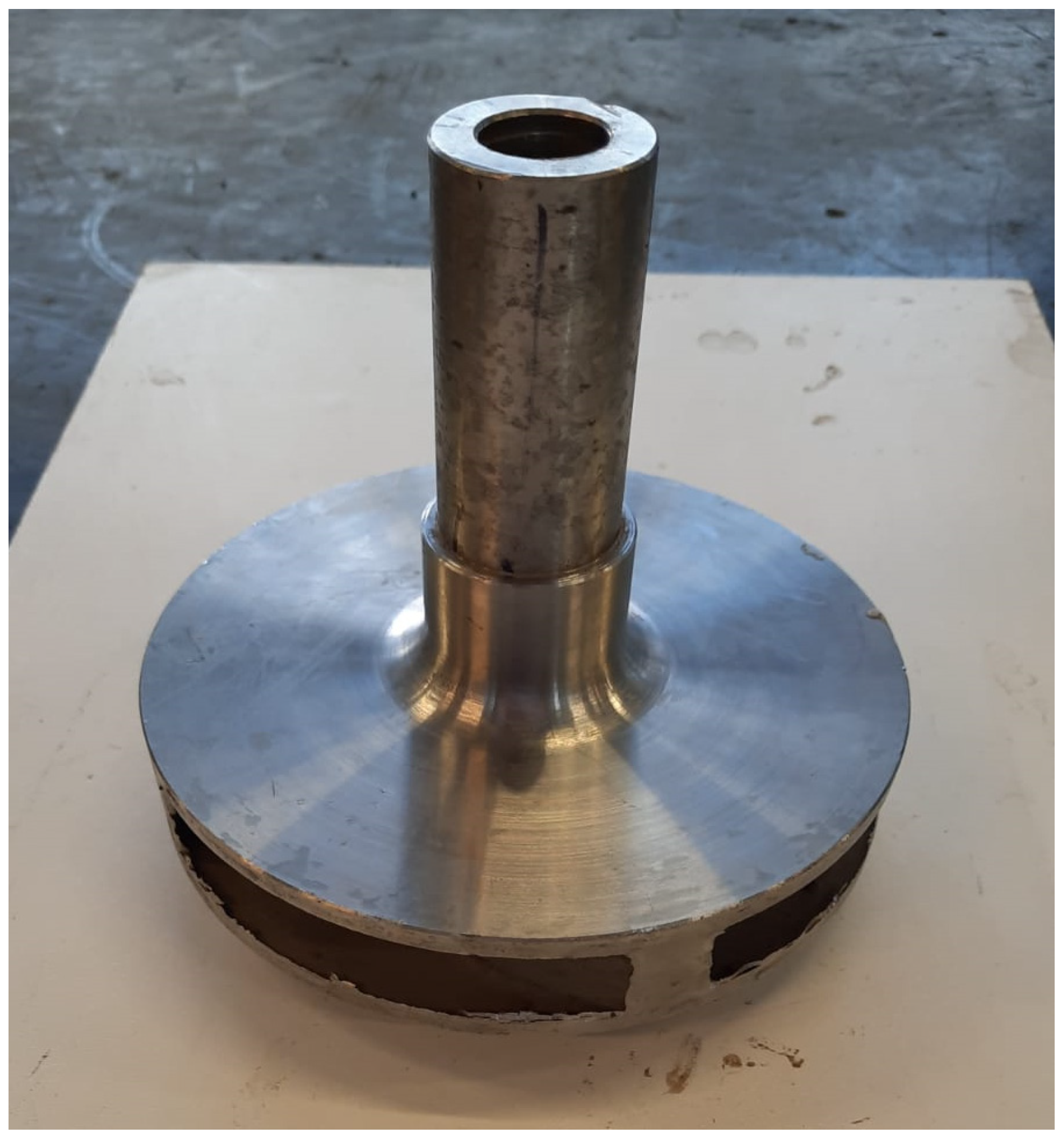
This scientific paper focuses on analyzing a pump impeller constructed from AISI 316L austenitic stainless steel. AISI 316L stands out as the preferred material for pump impellers owing to its exceptional resistance to corrosion, particularly in aggressive environments such as marine and chloride-laden fluids. The inherent qualities of AISI 316L, including longevity, high-temperature resilience, and ease of hygiene maintenance, make it an optimal choice for demanding applications in industries like pharmaceuticals and food processing. Notably, the impeller was produced through the sand casting process, a method frequently employed in pump manufacturing due to its cost-effectiveness and suitability for intricate designs. Sand casting enables the production of complex impeller shapes at a lower cost, striking a practical balance between efficiency and affordability in the manufacturing process.
Figure 1 shows the pump impeller after removal of the gating system, providing a visual reference for the discussed manufacturing method.
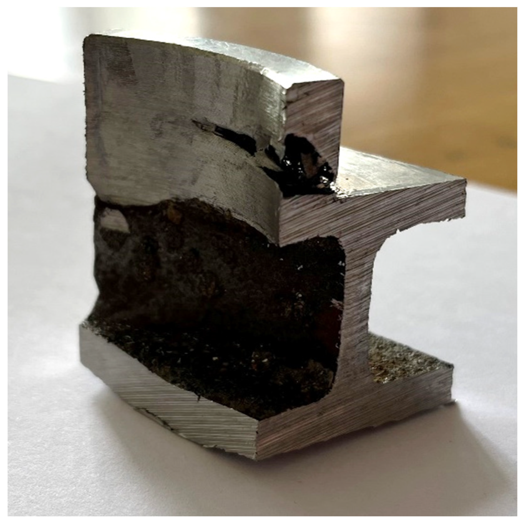
Upon visual inspection, the casting revealed no defects. Subsequent machining, specifically internal turning, exposed cavities at the entry points of the pump impeller, indicating product damage. This defect was identified as shrinkage porosity, as shown in
Figure 2. Shrinkage porosity occurs due to the shrinkage of metal during the solidification process, leading to incomplete structure of certain areas in the casting.
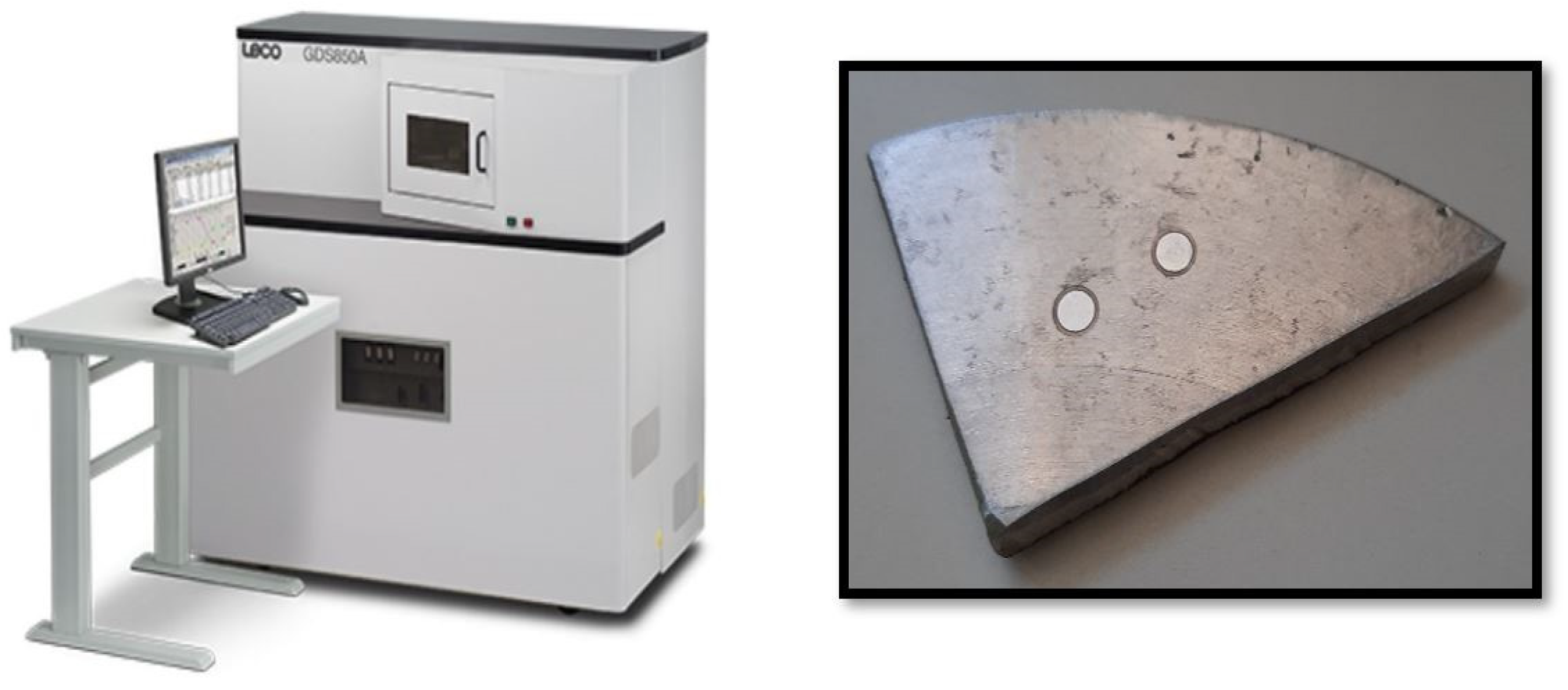
Identifying the precise cause of casting defects, particularly intricate issues like shrinkage porosity, is especially challenging in practical applications. Therefore, conducting a detailed material characterization becomes imperative. The initial step involves examining the chemical composition of the casting to confirm its alignment with the specifications for AISI 316L austenitic stainless steel. This analysis utilized the optical emission spectrometer GDS 850A, LECO (St. Joseph, MI, USA), as depicted in
Figure 3.
The chemical composition was tested and deviations were found for some chemical elements. Cr, Ni, and Mo levels are slightly lower than required by the standard for AISI 316L steel (
Table 1). P and S levels are slightly higher and the Si level is higher than required. The reduced chromium content in the casting can lead to a reduction in corrosion resistance, as chromium is a critical element for forming a protective oxide layer. Chromium is an alpha-forming element that expands the range of ferrite stability, influencing the microstructure and potentially affecting mechanical properties. Conversely, nickel and manganese are highly gamma-forming elements, imparting stability and broadening the austenitic phase field. Nickel contributes to corrosion resistance and enhances ductility, while manganese can impact hardenability.
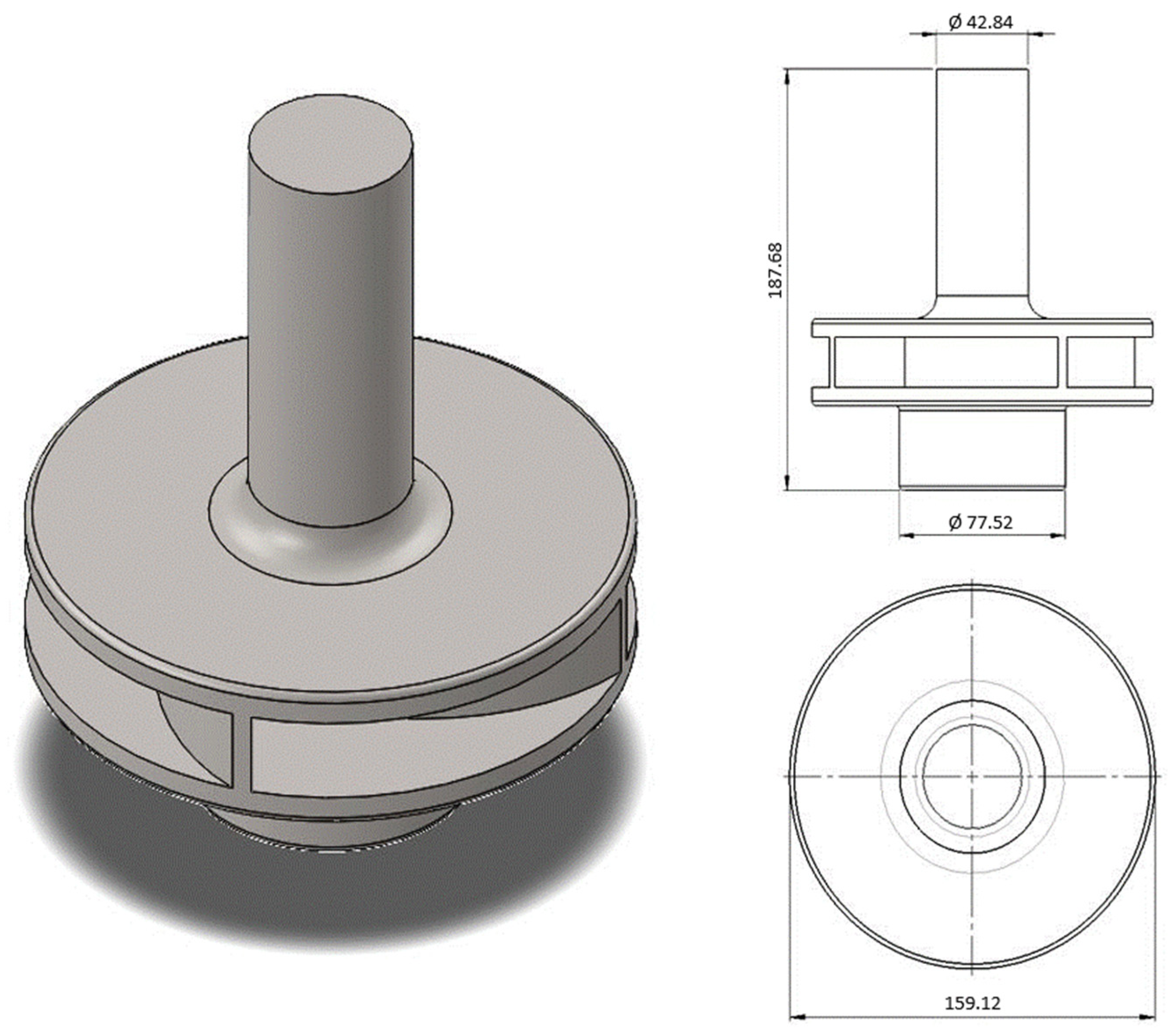
After chemical characterization, the proper design of the gating system and the feeding system were analyzed and the casting parameters were checked. All dimensions of the pump impeller were precisely measured and defined before being incorporated into a designed CAD model using SolidWorks software (2020 SP3). The resulting model is shown in
Figure 4, providing comprehensive isometric, front, and top views of the pump impeller along with corresponding dimensions.
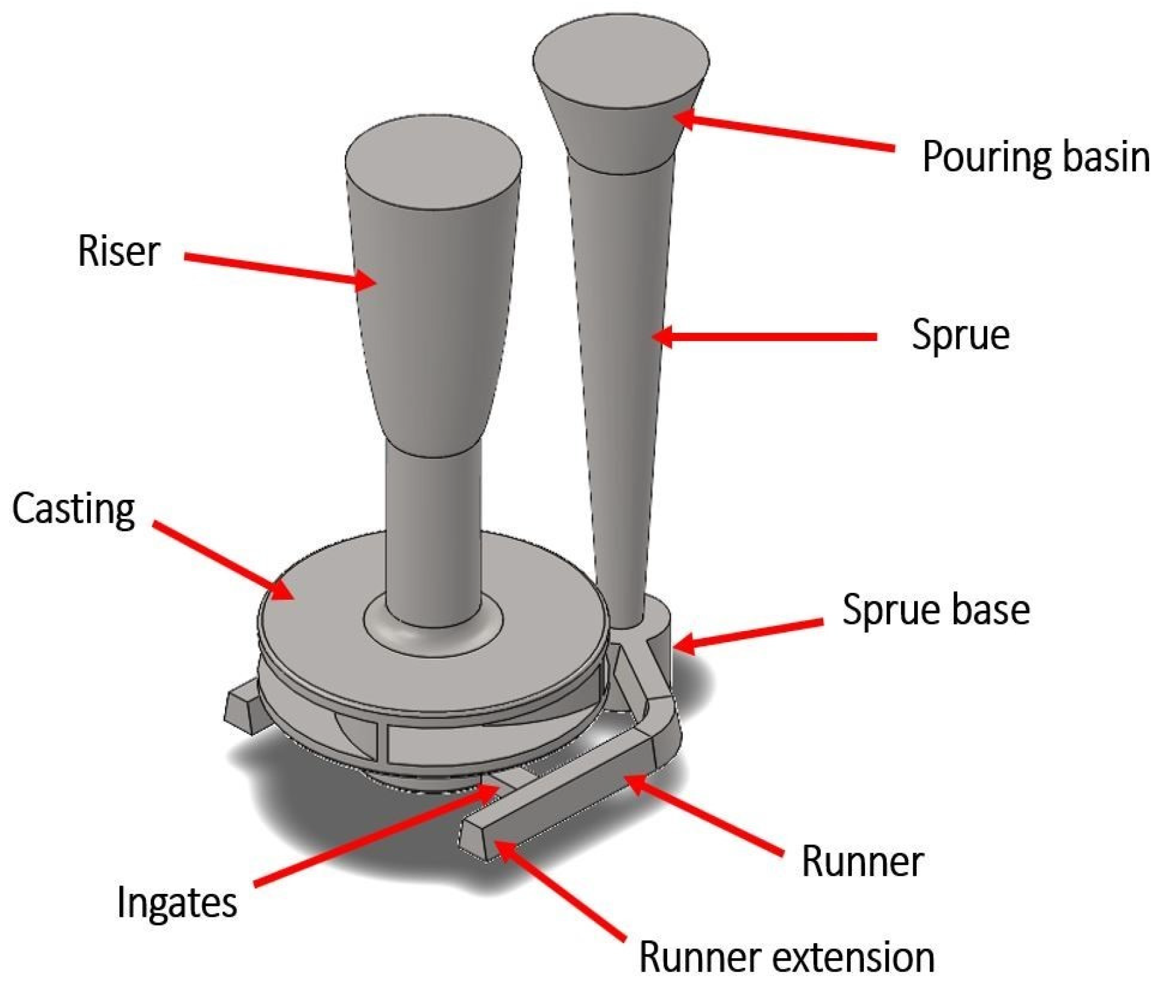
The gating and feeding systems were also designed identically. In this way, an identical shape was achieved as in the real experiment. The gating system consisted of a pouring basin, sprue, sprue base, two runners, and two ingates, while the feeding system, represented by the riser, was positioned at the top of the pump impeller shaft. The vertical distance between the molten metal level in the pouring basing and the ingates level was 370 mm. The cross section of the bottom of the sprue was 315 mm
2, the runner was 2 × 270 mm
2, and the ingates were 2 × 150 mm
2. The gating and feeding system for the impeller pump in the form of a CAD model with labeled parts is shown in
Figure 5.
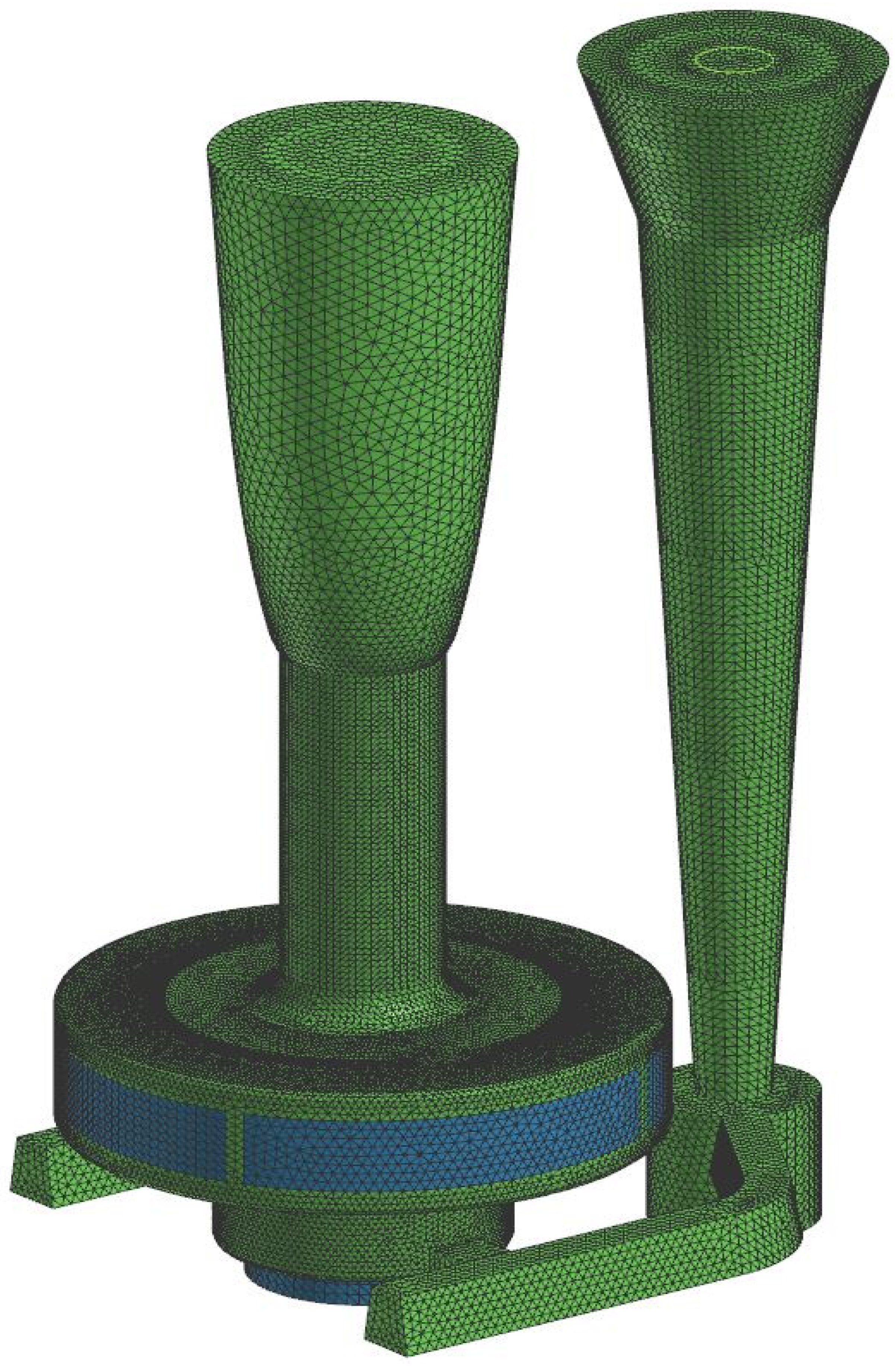
The CAD model was imported into the ProCAST casting simulation software. The mesh was generated by the finite element method with the densest mesh on the casting (pump impeller), followed by the gating system then the rise and core, and finally the mold with the rarest generated mesh.
Figure 6 shows the distribution of the generated mesh without molds. The final number of 2D and 3D elements was 2,028,526.
All material data and casting parameters were entered in the software ProCAST as used in the real casting process. The mold was made of green sand and the core was made using furan resin sand in a No-bake process. The mold and the core were coated with a water-based coating with a coating thickness of 100 µm. The molten metal was AISI 316L stainless steel. Its liquidus temperature is 1420 °C, while the solidus temperature is 1197 °C. The pouring temperature in sand casting with complex geometry is usually 100–150 °C higher than the liquidus temperature of the molten metal, and in this process, it was 1550 °C. Thermal conductivity varies depending on temperature and was 26 W/mK at pouring temperature and 14 W/mK at room temperature. The latent heat of fusion was 273 kJ/kg. The mass of the molten metal that needed to be poured into the mold was 12.5 kg. The ProCAST software automatically recognizes the contact of surfaces with different thermal conductivity. Accordingly, it was necessary to define heat transfer compound (HTC).
Table 2 shows HTC amounts for different interfaces in contact.
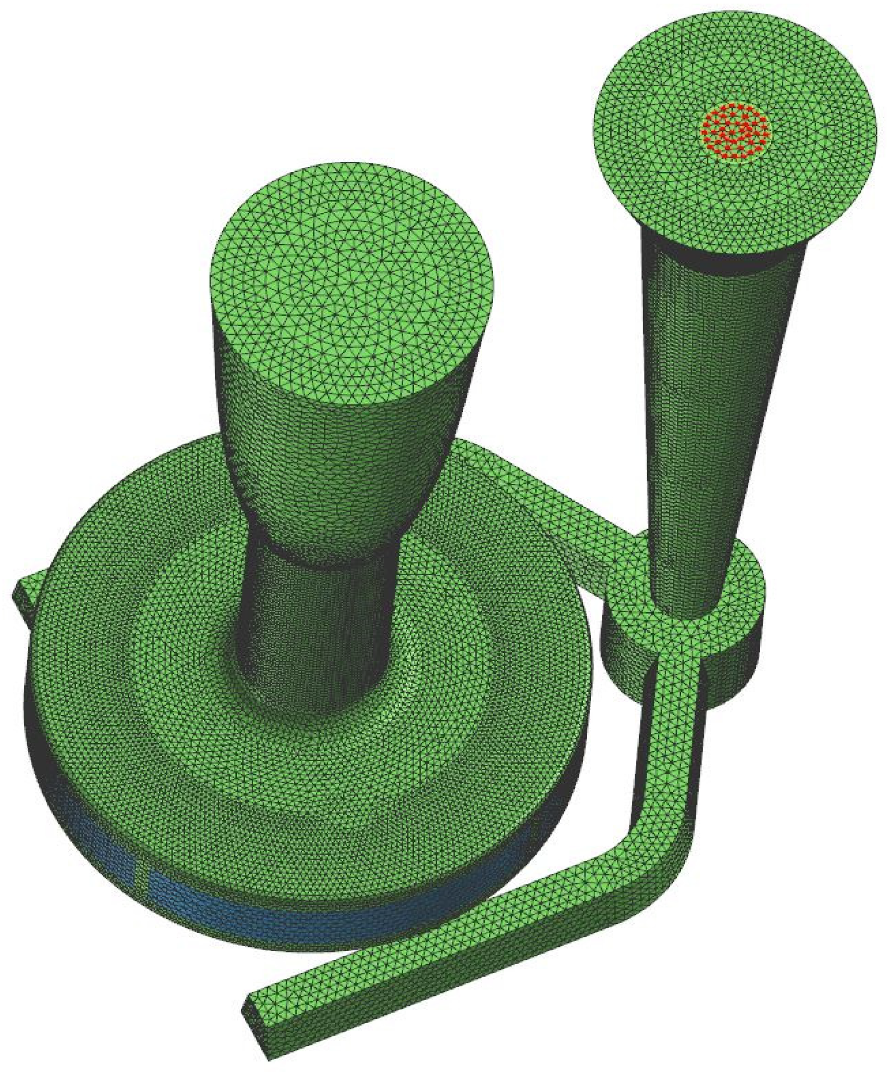
The boundary conditions that were defined were heat dissipation and fluid flow velocity. Heat dissipation was defined by cooling the molten metal in the mold to room temperature through natural airflow. The pouring time was approximately 12 s, leading to a pouring velocity of 608 mm/s. For the fluid velocity, it was necessary to define the point and diameter of the inlet, marked with a red circle in
Figure 7. Further, by inserting the pouring time which was approximately amount of 12 s, the software calculated the pouring velocity, which was 608 mm/s.
The
–
ε model of turbulence was used to simulate the molten metal filling into the mold and in calculating was approached with two equations. The first was the conservation equation for turbulent kinetic energy and it was described in the following expression [
49]:
where are
and
(turbulence generation rate):
The second was the turbulence dissipation rate and it was described in the following expression [
49]:
where
(turbulent eddy viscosity) is:
while the default values of constants are in
Table 3:
The solidification of the molten metal was calculated with the Johnson–Mehl approximation, assuming that the solid/liquid interface is weighted by a factor of
to account for collision grains towards the later part of solidification [
49]:
where
is the radius of the eutectic grain and
is the substrate density. When the instantaneous nucleation model is used,
becomes a function of the cooling rate. For continuous nucleation,
becomes a function of temperature.
3. Experimental Results
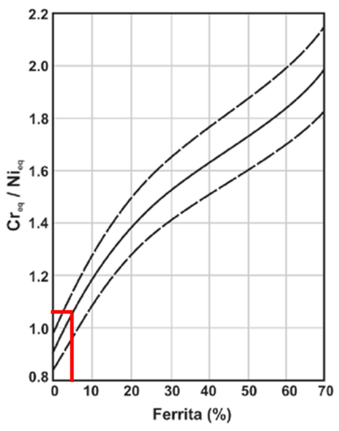
For evaluation and control of ferrite in the microstructure of stainless steel castings, the Schoefer diagram is used as a standard. The calculation requires the ratio of chromium (
Cre) and nickel (
Nie) equivalents, which are calculated according to the following expressions [
48]:
The Schoefer diagram, constructed with the calculated chromium and nickel equivalent composition ratio, is depicted in
Figure 8. The
Cre/
Nie composition ratio is 1.05, which results in a Ni content of approximately 5% in the microstructure.
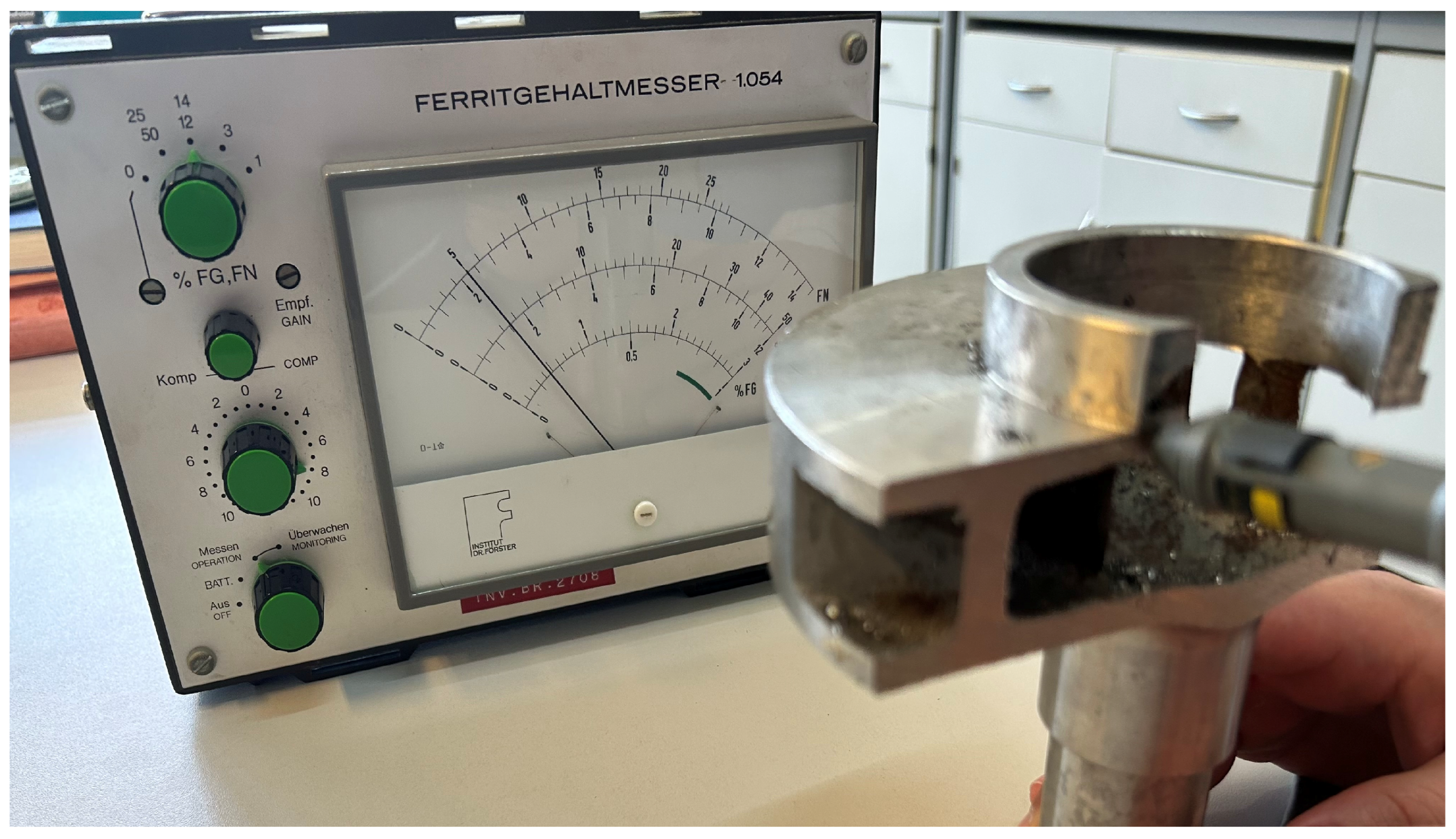
The accuracy of the Schoefer diagram was determined using a ferritometer.
Figure 9 displays the testing of ferrite content in the austenitic microstructure with device Ferritgehaltmesser 1.054. The device measured a ferrite content of 5%, thereby validating the results obtained in the Schoefer diagram.
The higher presence of ferrite in the austenitic microstructure results in increased shrinkage porosity due to its greater volumetric contraction during solidification, leading to the formation of internal voids within the material. On the other hand, the presence of ferrite in the austenitic microstructure can improve weldability and magnetic permeability, but it is usually avoided because it reduces the corrosion resistance of the material, increases its sensitivity to wear, and reduces its mechanical properties such as strength and hardness.
The subsequent step focused on investigating the material’s microstructure at the site of shrinkage porosity.
Figure 10 shows a section of the pump impeller chosen for detailed microstructure analysis, providing visual insights into the observed porosity issues. This selected segment was cut using a band saw.
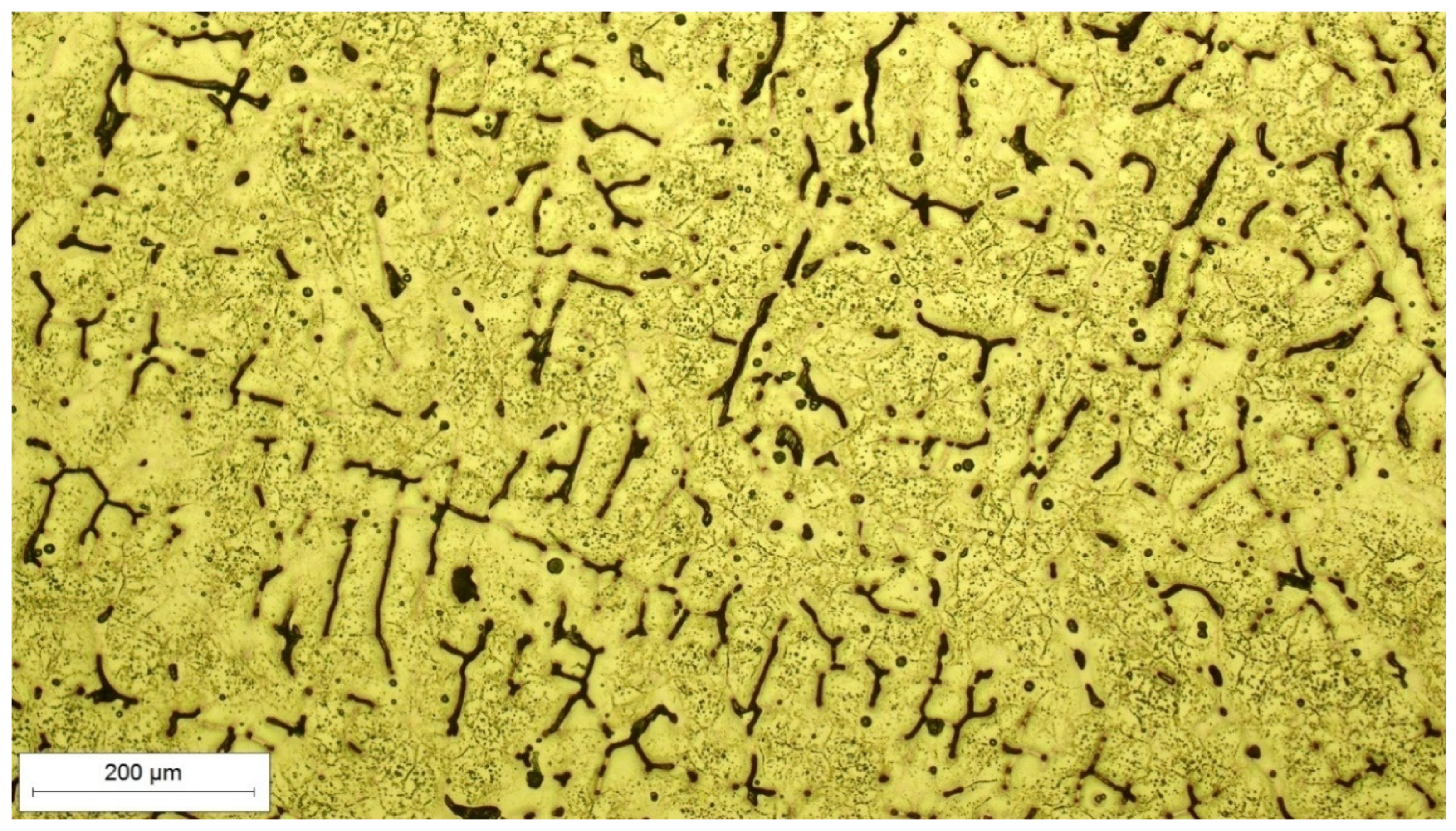
After the cutting, the specimen for microstructural analysis was mounted in the conductive resin, ground, polished, and electrochemically etched in the 10% oxalic acid at a voltage of 12 V for three minutes. The microstructure was analyzed using the light microscope OLYMPUS GX51F-5 with the attached Olympus DP-25 CCD camera.
Figure 11 shows the distinctive two-phase microstructure of the impeller material, which consists of an austenite matrix and the ferrite phase in the form of black lines. The austenitic matrix, characterized by a face-centered cubic (FCC) crystal lattice, imparts corrosion resistance and high-temperature stability. The discernible ferrite phase, observed as dark lines within the microstructure, typically exhibits a body-centered cubic (BCC) crystal structure. The coexistence of these phases is a result of the solidification process during casting, influenced by factors such as alloy composition, cooling rates, and solidification conditions. The segregation of ferrite along specific boundaries or areas within the austenitic matrix is a common occurrence in cast stainless steels, influencing mechanical properties, tribological properties, and magnetic behavior.
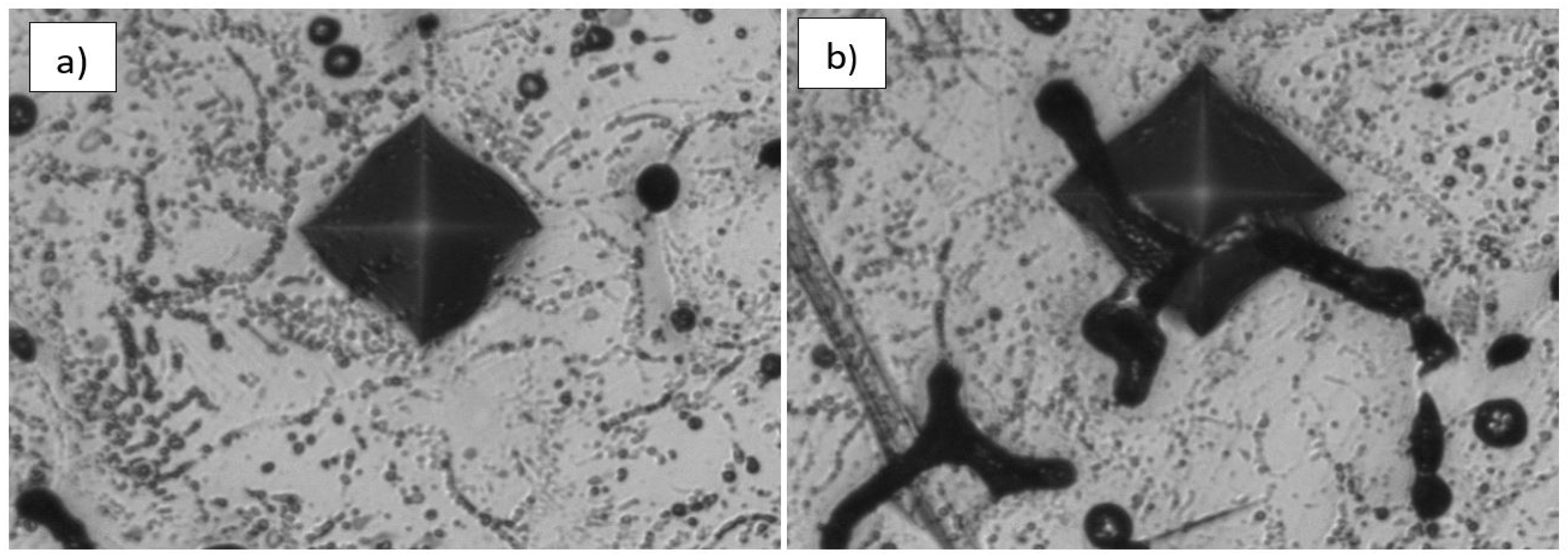
Microhardness was measured using the Vickers method HV 0.1 with a test load of 0.9807 N. It was measured on both phases separately: in the region where the austenite phase is dominant, and in the region where the ferrite phase is dominant.
Figure 12 shows the resulting indentations in the predominantly austenitic phase (a) and in the predominantly ferritic phase (b) of the sample.
The pronounced contrast in microhardness values between the predominantly austenitic and ferritic phases highlights the mechanical distinctions within the dual-phase microstructure. The elevated average microhardness of 133 HV0.1 in the predominantly austenitic region consistently reflects the heightened strength and hardness commonly associated with austenitic stainless steels. In contrast, the diminished average microhardness of 96 HV0.1 in the predominantly ferritic phase is in line with the anticipated lower hardness characteristic of ferritic structures.
Author Contributions
Conceptualization, Z.S. and S.Š.; methodology, B.B. and K.J.; software, K.J.; validation, B.B.; formal analysis, Z.S. and S.Š.; investigation, B.B. and K.J.; resources, K.J.; data curation, B.B.; writing—original draft preparation, K.J.; writing—review and editing, Z.S., S.Š. and B.B.; visualization, K.J.; supervision, B.B. All authors have read and agreed to the published version of the manuscript.
Funding
This research received no external funding.
Data Availability Statement
The original contributions presented in the study are included in the article, further inquiries can be directed to the corresponding authors.
Conflicts of Interest
The authors declare no conflict of interest.
References
- Graciano-Uribe, J.; Sierra, J.; Torres-Lopez, E. Instabilities and influence of geometric parameters on the efficiency of a pump operated as a turbine for micro hydro power generation: A review. J. Sustain. Dev. Energy Water Environ. Syst. 2021, 9, 1080321. [Google Scholar] [CrossRef]
- Tan, M.; Lu, Y.; Wu, X.; Liu, H.; Tian, X. Investigation on performance of a centrifugal pump with multi-malfunction. J. Low Freq. Noise Vib. Act. Control 2021, 40, 740–752. [Google Scholar] [CrossRef]
- Meerakaviyad, D.; Keville, T.; Prakash, A.; Abdullah, S.; Hamad, F. Effect of Geometric Configuration of the Impeller on the Performance of Liquivac Pump: Single Phase Flow (Water). Fluids 2022, 7, 45. [Google Scholar] [CrossRef]
- Reddy, T.D.; Manikantesh, K. Design and Analysis of Centrifugal Pump Impeller Using Composite Materials. J. Emerg. Technol. Innov. Res. 2022, 9, 278–283. [Google Scholar]
- Arun Shankar, V.K.; Umashankar, S.; Paramasivam, S.; Hanigovszki, N. A comprehensive review on energy efficiency enhancement initiatives in centrifugal pumping system. Appl. Energy 2016, 181, 495–513. [Google Scholar] [CrossRef]
- Da Costa Bortoni, E.; De Almeida, R.A.; Viana, A.N.C. Optimization of parallel variable-speed-driven centrifugal pumps operation. Energy Effic. 2008, 1, 167–173. [Google Scholar] [CrossRef]
- Xu, Z.; Kong, F.; Zhang, K.; Zhu, H.; Wang, J.; Qiu, N. Optimization of the impeller for hydraulic performance improvement of a high-speed magnetic drive pump. Adv. Mech. Eng. 2022, 14, 16878132221104576. [Google Scholar] [CrossRef]
- Stratogiannis, F.I.; Galanis, N.I.; Karkalos, N.E.; Markopoulos, A.P. Optimization of the Manufacturing Strategy, Machining Conditions, and Finishing of a Radial Impeller. Machines 2020, 8, 1. [Google Scholar] [CrossRef]
- Frier, S.; Sorokes, J.M.; Burkardt, N. Impeller manufacturing—Understanding the methods & their impact on performance. In Proceedings of the Turbomachinery & Pump Symposia, Houston, TX, USA, 14 September 2020. [Google Scholar]
- Zinchenko, A.; Baiul, K.; Krot, P.; Khudyakov, A.; Vashchenko, S.; Banasiewicz, A.; Wróblewski, A. Materials Selection and Design Options Analysis for a Centrifugal Fan Impeller in a Horizontal Conveyor Dryer. Materials 2021, 14, 6696. [Google Scholar] [CrossRef]
- Laney, S.; Bauer, D.; Ando, A. Evalution of Various Methods for Manufacturing One Piece, Small Tip Opening Centrifugal Compressor Impellers. In Proceedings of the Asia Turbomachinery & Pump Symposium, Singapore, 22–25 February 2016. [Google Scholar]
- Thanikachalam, V. The Corrosion and Erosion of Centrifugal Pumps in a Marine Environment: Causes, Effects and Mitigation. Int. J. Adv. Eng. Res. 2017, 13, 34–52. [Google Scholar]
- Augusto Massaro, G.; Zoqui, E.; Benati, D. Viability study of production of enclosed impellers for centrifugal pumps by investment casting process. In Proceedings of the Congresso Brasileiro de Engenharia de Fabricação, Santa Catarina, Brasil, January 2017. [Google Scholar]
- Saikaew, C.; Wiengwiset, S. Optimization of molding sand composition for quality improvement of iron castings. Appl. Clay Sci. 2012, 67–68, 26–31. [Google Scholar] [CrossRef]
- Nimbulkar, S.L.; Dalu, R.S. Design optimization of gating and feeding system through simulation technique for sand casting of wear plate. Perspect. Sci. 2016, 8, 39–42. [Google Scholar] [CrossRef]
- Hawaldar, N.; Zhang, J. A comparative study of fabrication of sand casting mold using additive manufacturing and conventional process. Int. J. Adv. Manuf. Technol. 2018, 97, 1037–1045. [Google Scholar] [CrossRef]
- Hafeez, F.; Ahmed, N.; Ali, M.A.; Farooq, M.U.; AlFaify, A.Y.; Rehman, A.U. A comprehensive efficiency evaluation of conventional and ablation sand casting on the example of the AlSi7Mg alloy impeller. Int. J. Adv. Manuf. Technol. 2022, 121, 3653–3672. [Google Scholar] [CrossRef]
- Hernández, F.; Fragoso, A. Fabrication of a Stainless-Steel Pump Impeller by Integrated 3D Sand Printing and Casting: Mechanical Characterization and Performance Study in a Chemical Plant. Appl. Sci. 2022, 12, 3539. [Google Scholar] [CrossRef]
- Dhanush, S.; Balaganesh, S.; Vijayakumar, V. A Review on Defect Minimization in Sand Casting. Nat. Volatiles Essent. Oils 2021, 8, 3076–3093. [Google Scholar]
- Sertucha, J.; Lacaze, J. Casting Defects in Sand-Mold Cast Irons—An Illustrated Review with Emphasis on Spheroidal Graphite Cast Irons. Metals 2022, 12, 504. [Google Scholar] [CrossRef]
- Velliyangiri, B.; Pranava Kumar, S.; Priyadarsan, R.; Elango, M.; Jegan, S. Design and Fabrication of Casting Defect Segregation Machine. Int. Res. J. Mod. Eng. Technol. Sci. 2022, 4, 1434–1439. [Google Scholar]
- Budzik, G. Possibilities of Using Vacuum Casting Process for Manufacturing Cast Models of Turbocharger Impellers. J. KONES Powertrain Transp. 2007, 14, 125–130. [Google Scholar]
- Suthar, J.; Persis, J.; Gupta, R. Analytical modeling of quality parameters in casting process—Learning-based approach. Int. J. Qual. Reliab. Manag. 2022, 40, 1821–1858. [Google Scholar] [CrossRef]
- Borikar, G.P.; Chavan, S.T. Optimization of Casting Yield in Multi-cavity Sand Moulds of Al-alloy Components. Mater. Today Proc. 2020, 28, 819–824. [Google Scholar] [CrossRef]
- Sama, S.R.; Badamo, T.; Manogharan, G. Case Studies on Integrating 3D Sand-Printing Technology into the Production Portfolio of a Sand-Casting Foundry. Int. J. Met. 2020, 14, 12–24. [Google Scholar] [CrossRef]
- Olorunfemi, B.J.; Adejuyigbe, S.B.; Adekunle, A.A. Casting and Performance Evaluation of Pump Impeller and Housing using Local Raw Materials. J. Eng. Technol. 2018, 3, 7–11. [Google Scholar] [CrossRef]
- Lakhdar, Y.; Tuck, C.; Binner, J.; Terry, A.; Goodridge, R. Additive manufacturing of advanced ceramic materials. Prog. Mater. Sci. 2021, 116, 100736. [Google Scholar] [CrossRef]
- Isamotu, O.F.; Raji, K.M. Performance Evaluation of Different Materials as Chills in Sand Casting of Aluminum Alloy. ACTA Tech. Corviniensis Bull. Eng. 2019, 3, 81–84. [Google Scholar]
- Bijagare, V.; Deulgaonkar, V. Modeling and Finite Element Analysis for a Casting Defect in Thin-Wall Structures. Int. J. Emerg. Eng. Res. Technol. 2015, 3, 77–82. [Google Scholar]
- Sivarupan, T.; Balasubramani, N.; Saxena, P.; Nagarajan, D.; El Mansori, M.; Salonitis, K.; Jolly, M.; Dargusch, M.S. A review on the progress and challenges of binder jet 3D printing of sand moulds for advanced casting. Addit. Manuf. 2021, 40, 101889. [Google Scholar] [CrossRef]
- Sithole, C.; Nyembwe, K.; Olubambi, P. Process knowledge for improving quality in sand casting foundries: A literature review. Procedia Manuf. 2019, 35, 356–360. [Google Scholar] [CrossRef]
- Mohammadian, Z.; Ayremlouzadehb, H.; Doniavi, A. Numerical Investigation on the Effect of Mold Design on Shrinkage of Sand Casted Multistage BB3-6×6 Pump Casing. Int. J. Eng. 2016, 29, 1175–1182. [Google Scholar]
- Khan, M.A.A.; Sheikh, A.K. Simulation tools in enhancing metal casting productivity and quality: A review. J. Eng. Manuf. 2016, 230, 1799–1817. [Google Scholar] [CrossRef]
- Seetharamu, K.N.; Paragasam, R.; Quadir, G.A.; Zainal, Z.A.; Prasad, B.S.; Sundararajan, T. Finite element modelling of solidification phenomena. Sadhana 2001, 26, 103–120. [Google Scholar] [CrossRef][Green Version]
- Baghani, A.; Davami, P.; Varahram, N.; Shabani, M.O. Investigation on the Effect of Mold Constraints and Cooling Rate on Residual Stress during the Sand-Casting Process of 1086 Steel by Employing a Thermomechanical Model. Metall. Mater. Trans. B 2014, 45, 1157–1169. [Google Scholar] [CrossRef]
- Choudhari, C.M.; Narkhede, B.E.; Mahajan, S.K. Casting Design and Simulation of Cover Plate Using AutoCAST-X Software for Defect Minimization with Experimental Validation. Procedia Mater. Sci. 2014, 6, 786–797. [Google Scholar] [CrossRef]
- Iqbal, H.; Sheikh, A.K.; Al-Yousef, A.; Younas, M. Mold Design Optimization for Sand Casting of Complex Geometries Using Advance Simulation Tools. Mater. Manuf. Process. 2012, 27, 775–785. [Google Scholar] [CrossRef]
- Baghani, A.; Bahmani, A.; Davami, P.; Varahram, N.; Shabani, M.O. Numerical Investigation of the Effect of Sprue Base Design on the Flow Pattern of Aluminum Gravity Casting. J. Mater. Des. Appl. 2013, 344, 43–53. [Google Scholar] [CrossRef]
- Hafeez, F.; Hussain, S.; Ahmad, W.; Jahanzaib, M. Optimisation of Sand Casting Process for Impeller Using Taguchi Methodology. NED Univ. J. Res. 2020, 2, 23–33. [Google Scholar] [CrossRef]
- Sama, S.R.; MacDonald, E.; Voigt, R.; Manogharan, G. Measurement of Metal Velocity in Sand Casting during Mold Filling. Metals 2019, 9, 1079. [Google Scholar] [CrossRef]
- Pant, G.; Reddy, M.; Praveen, A.; Parashar, S.; Kareem; Nijhawan, G. Advanced Casting Techniques for Complex-Shaped Components: Design, Simulation and Process Control. In Proceedings of the 15th International Conference on Materials Processing and Characterization, Web of Conferences, Newcastle, UK, 6 October 2023. [Google Scholar]
- Dučić, N.; Manasijević, S.; Jovičić, A.; Ćojbašić, Ž.; Radiša, R. Casting Process Improvement by the Application of Artificial Intelligence. Appl. Sci. 2022, 12, 3264. [Google Scholar] [CrossRef]
- Ktari, A.; El Mansori, M. Intelligent approach based on FEM simulations and soft computing techniques for filling system design optimisation in sand casting processes. Int. J. Adv. Manuf. Technol. 2021, 114, 981–995. [Google Scholar] [CrossRef]
- You, L.; Yao, L.; Li, X.; Jia, G.; Lv, G. Numerical simulation and casting process optimization of cast steel node. Int. J. Adv. Manuf. Technol. 2023, 126, 5215–5225. [Google Scholar] [CrossRef]
- Horr, A.M.; Kronsteiner, J. On Numerical Simulation of Casting in New Foundries: Dynamic Process Simulations. Metals 2020, 10, 886. [Google Scholar] [CrossRef]
- Chen, Z.; Li, Y.; Zhao, F.; Li, S.; Zhang, J. Progress in numerical simulation of casting process. Meas. Control 2022, 55, 257–264. [Google Scholar] [CrossRef]
- LECO Corporation. GDS850A Atomic Emission Spectrometer. Available online: https://www.ardutek.com/gds850-glow-discharge-atomik-emisyon-spektroskopisi-atomic-emission-spectroscopy-leco-en.html (accessed on 15 October 2023).
- Davis, J.R. ASM Specialty Handbook: Stainless Steels; ASM International: Detroit, MI, USA, 1994; pp. 4–69. [Google Scholar]
- UES Software, Inc. ProCAST User’s Manual & Technical Reference, 1996–1997; UES Software, Inc.: Dayton, OH, USA, 2011. [Google Scholar]
Figure 1.
Sand casted pump impeller, AISI 316L.
Figure 2.
Shrinkage porosity in the casting.
Figure 3.
Testing the chemical composition of the sample with the optical emission spectrometer GDS 850A, LECO (Reprinted with permission from ref. [
47], 2024 LECO Corporation).
Figure 4.
CAD model of a pump impeller in isometric view, front view, and top view.
Figure 5.
CAD model of a pump impeller with associated gating system and feeding system.
Figure 6.
The distribution of elements on the CAD model (Green is a casting and blue is the core).
Figure 7.
Spot and diameter of inlet of molten metal (Red color is indicated inlet).
Figure 8.
Ferrite content, expressed in the Schoefer diagram [
48].
Figure 9.
Measurement of the content of ferrite in the austenite microstructure of the pump impeller.
Figure 10.
Pump impeller part for microstructure analysis at the site where shrinkage porosity occurred.
Figure 11.
Microstructure of the casted AISI 316L material.
Figure 12.
Microhardness measurement indentations: (a) predominantly austenitic phase; (b) predominantly ferritic phase.
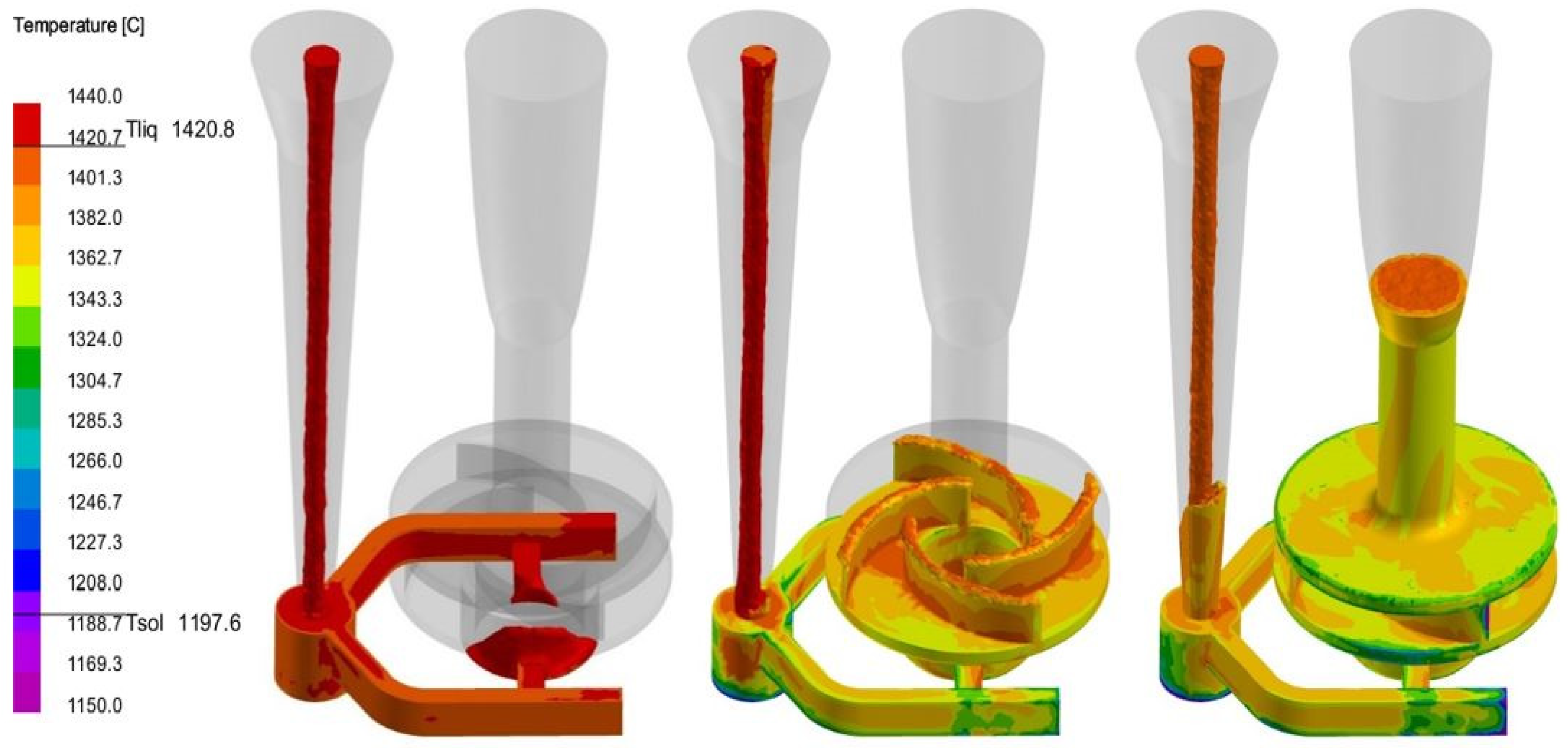
Figure 13.
Filling of the mold cavity with molten metal at different stages.
Figure 14.
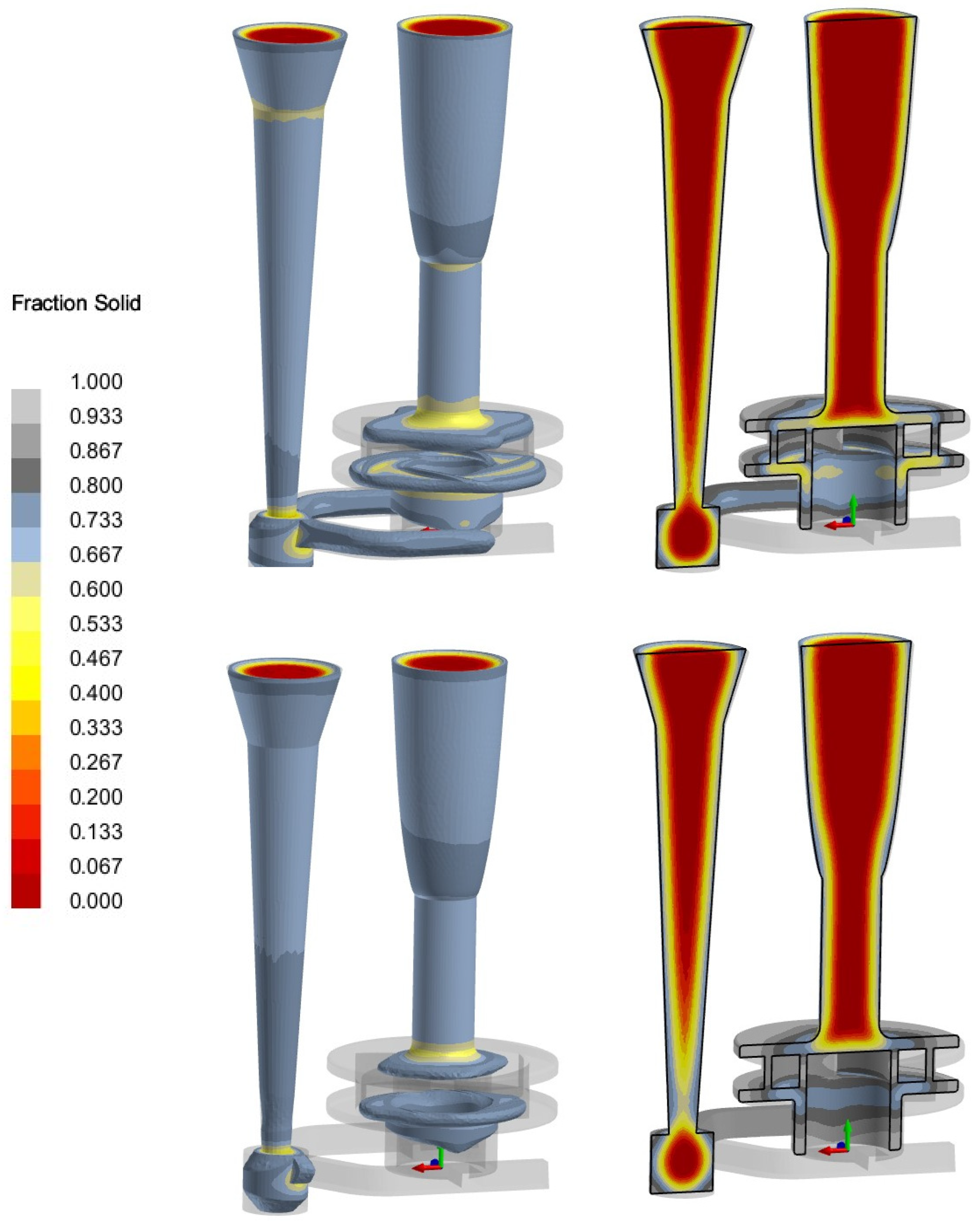
Solidification process in two different stages.
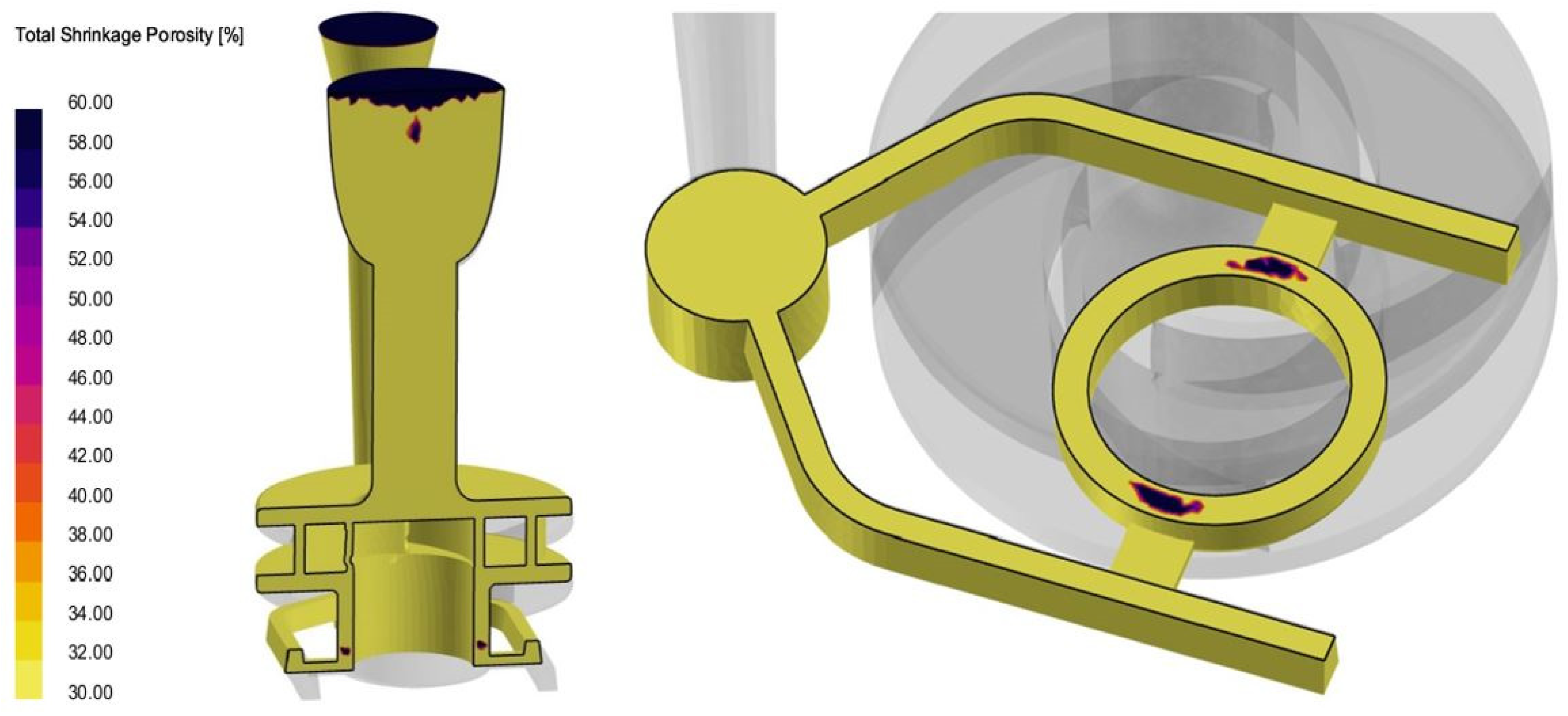
Figure 15.
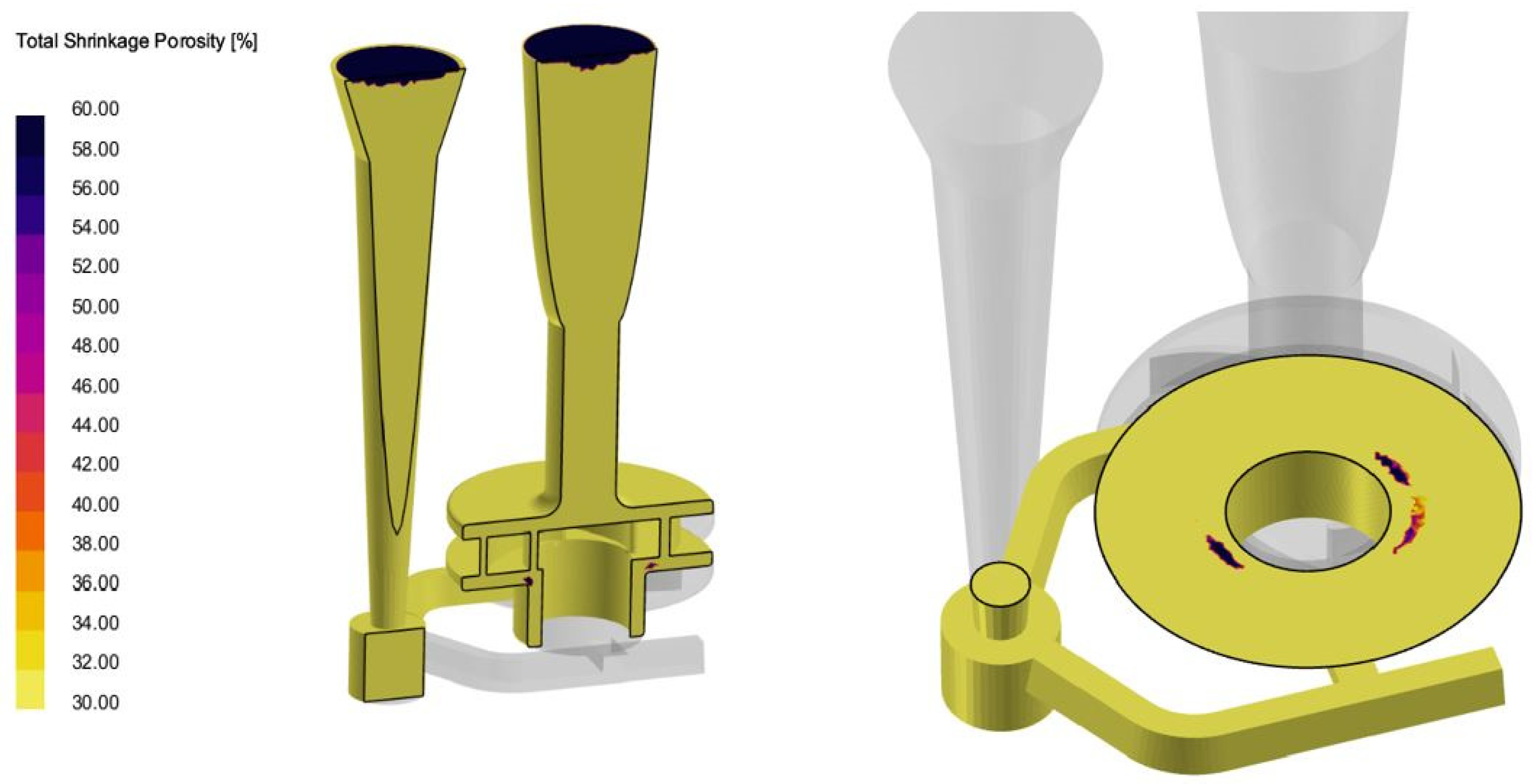
Locations of the shrinkage porosity in the casting with a probability of more than 60%.
Figure 16.
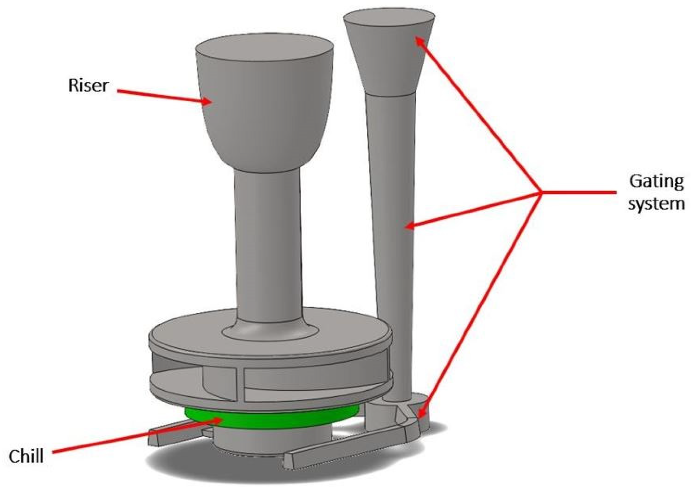
CAD model of a pump impeller with improved gating and feeding system and additional chill.
Figure 17.
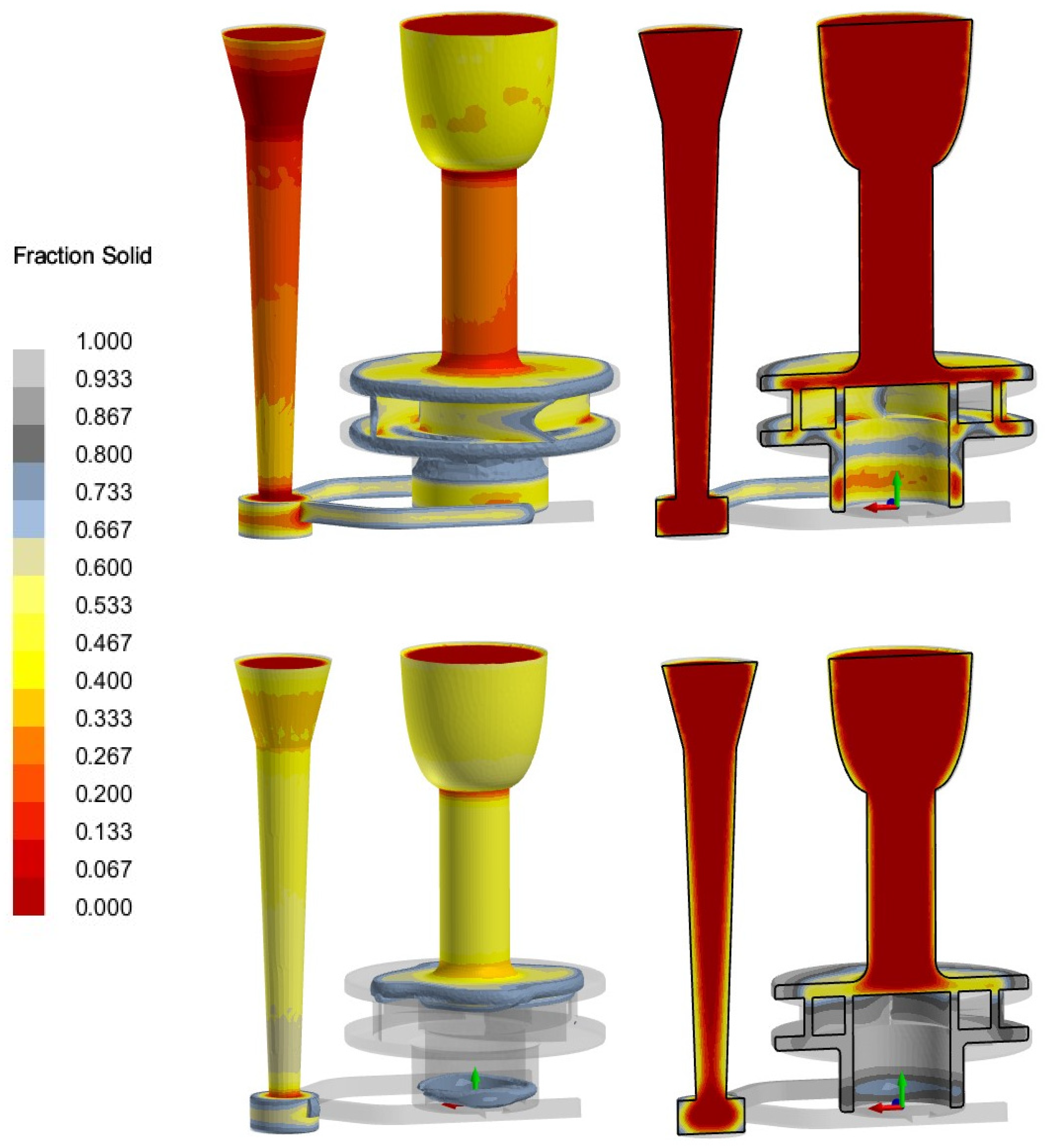
Solidification process in two different stages in the improved version of gating system.
Figure 18.
Locations of the shrinkage porosity in the gating system with a probability of more than 60% in the improved version.
Table 1.
Chemical composition of the casting [
48].
| | Chemical Composition (%) |
|---|
| C | Si | Mn | Cr | Mo | Ni | N | P | S | Fe |
|---|
| Casting | 0.01 | 1.31 | 0.47 | 15.20 | 1.90 | 9.64 | 0.09 | 0.048 | 0.016 | Balance |
| AISI 316L | ≤0.03 | ≤1.00 | ≤2.00 | 16–18 | 2–3 | 10–14 | ≤0.1 | ≤0.045 | ≤0.03 | Balance |
Table 2.
The amount of HTC at contacts of different interfaces.
| Interfaces in Contact | HTC (W/m2K) |
|---|
| Molten metal/mold | 400 |
| Molten metal/core | 500 |
| Mold/core | 100 |
Table 3.
Default values of constants [
49].
| | | | |
|---|
| 1.0 | 1.3 | 1.44 | 1.92 | 0.09 |
Table 4.
The amount of HTC between chill and mold and between chill and molten metal.
| Interfaces in Contact | HTC (W/m2K) |
|---|
| Chill/mold | 500 |
| Chill/molten metal | 2000 |
| Disclaimer/Publisher’s Note: The statements, opinions and data contained in all publications are solely those of the individual author(s) and contributor(s) and not of MDPI and/or the editor(s). MDPI and/or the editor(s) disclaim responsibility for any injury to people or property resulting from any ideas, methods, instructions or products referred to in the content. |
© 2024 by the authors. Licensee MDPI, Basel, Switzerland. This article is an open access article distributed under the terms and conditions of the Creative Commons Attribution (CC BY) license (https://creativecommons.org/licenses/by/4.0/).


