Article

Insight into the Hot Corrosion Behavior of FeMnCrSi/TiC Coatings at 900 °C

1
State Key Laboratory of Featured Metal Materials and Life-Cycle Safety for Composite Structures, MOE Key Laboratory of New Processing Technology for Nonferrous Metals and Materials, School of Resources, Environment and Materials, Guangxi University, Nanning 530004, China
2
Center of Ecological Collaborative Innovation for Aluminum Industry in Guangxi, Nanning 530004, China
3
Key Laboratory of High-Performance Structural Materials and Thermo-Surface Processing, Guangxi University, Education Department of Guangxi Zhuang Autonomous Region, Nanning 530004, China
*
Author to whom correspondence should be addressed.
Metals 2024, 14(5), 504; https://doi.org/10.3390/met14050504
Submission received: 8 March 2024 / Revised: 10 April 2024 / Accepted: 12 April 2024 / Published: 26 April 2024

Abstract

:
This study explores the deposition of an Fe-MnCrSi/TiC coating on 45 steel surfaces using high-velocity arc spraying technology, examining the microstructure and hot corrosion behavior of the resultant layer. The microstructure of the FeMnCrSi/TiC coating primarily consists of an α-Fe (BCC) solid solution, composed of Fe, Mn, Cr, Si, C, and other elements, with a minor presence of β-Fe (FCC) solid-solution phase and unmelted TiC particles. Following 100 h of cyclic 900 °C hot corrosion, Mn on the coating surface preferentially oxidizes, forming a manganese-rich oxide layer. This process reduces the oxygen partial pressure (O2) within the coating, prompting the formation of a dense Cr2O3 layer on the inner side of the oxide layer. Concurrently, the rapid diffusion of Mn and Cr elements triggers the generation of Mn- and Cr-deficient regions at the metal/oxide layer interface, inducing the transformation of the coated metal primary matrix from an FCC + BCC dual phase to an α-Fe (BCC) single phase. After the reaction, the hot corrosion weight gain of the coating reached 12.43 mg/cm2, approximately one-fourteenth of the weight gain of the 45 steel substrates. This weight gain adheres to the parabolic law, suggesting that the FeMnCrSi/TiC coating exhibits excellent corrosion resistance under the given conditions.

1. Introduction

Metallic materials are the cornerstone of modern industrial development and manufacturing [1]. However, the escalating problem of metal corrosion poses significant challenges. Baorong Hou et al. [2] reported that corrosion-related failures in China result in an annual loss of approximately RMB 2.1 trillion, or 3.34% of GDP. Thermal corrosion stands out as one of the primary contributors to these losses [3,4,5]. The formation of salt deposits on the surface of metals and alloys leads to the creation of a molten salt film at elevated temperatures, thereby accelerating surface corrosion in metallic materials. This process not only incurs substantial economic losses but also poses considerable safety risks [1,6,7].
Simultaneously, the implementation of appropriate corrosion mitigation methods can effectively decelerate the thermal corrosion reaction of metallic materials [8]. For instance, the utilization of cost-effective coatings with exceptional corrosion resistance through thermal spraying has demonstrated a potential to reduce thermal corrosion costs by 15% to 35%, establishing it as one of the most efficacious surface protection methods currently available [9]. Amongst the various thermal spraying technologies, high-velocity arc spraying (HVAS) technology stands out due to its remarkable spray efficiency and suitability for industrial automation applications [10], resulting in coatings characterized by a superior bond strength and minimal pores [11]. HVAS is widely used to improve the surface properties of steel components. In China, alloy materials are utilized in over 85% of coatings, with Fe-Ni stainless steel and Fe-Cr stainless steel being particularly prevalent coating materials [12,13,14]. Considering that nickel holds an expensive and strategic status as a metal, there is a critical need to develop novel iron-based alloy coatings, aimed at reducing the use of nickel.
Fe-Mn-Cr system alloys, renowned for their exceptional mechanical properties and high-temperature oxidation resistance below 600~900 °C, are cost-effective alternatives to Ni-based alloys in certain industrial sectors [14,15,16,17,18]. Extensive research has been conducted on the mechanism of high-temperature oxidative corrosion in Fe-Mn-Cr system alloys. Generally, elements such as Cr and Al can form corrosion-resistant oxides within the oxide layer of the alloy surface. Conversely, Mn typically reduces the oxidative corrosion resistance of the coating [19]. Therefore, recent studies suggest that increasing the Mn content in Fe-Mn-Cr system alloys can accelerate the formation of a Mn-rich oxide layer on the alloy surface under elevated temperature conditions and can facilitate rapid development of a dense Cr2O3 oxide film within the alloy [15,20,21]. Simultaneously, an increase in Mn content can alleviate stress at the metal/oxide interface, thereby mitigating cracking of the oxide layer [21]. In a separate study [22], an FeMnSiCrNi alloy was treated in a vacuum under the temperature of 1050 °C and preferential oxidation of Mn was observed, leading to the formation of gaseous-phase oxides. The alloy surface underwent a transformation resulting in the generation of oxides such as MnCr2O4 and Cr2O3. Concurrently, the parabolic constant (kp) derived from the squared change curve for weight gain exhibited a significant decrease by two orders of magnitude from 2.2 × 10⁻⁹ kg2/m4·s to 2.2 × 10⁻¹¹ kg2/m4·s when compared to the untreated sample.
These results validate the distinctive oxidation mechanism and exceptional high-temperature oxidation corrosion resistance of the Fe-Mn-Cr alloy, indicating its potential to partially substitute Fe-Ni or Ni-based coatings. However, limited research has been conducted on the microstructure and high-temperature hot corrosion mechanism of Fe-Mn-Cr alloy coatings. Therefore, in this paper, metal and metallic compound powders such as Fe, Mn, Cr, Si, and TiC were introduced to prepare powder core wires, which could improve the high-temperature corrosion (hot corrosion) properties. To combine the thermal stability and wear resistance of ceramic particles with the superior toughness of the metal matrix [23,24,25], TiC particles were incorporated into the coating material through HVAS onto 45 steel surfaces. The resulting composite coatings (FeMnCrSi/TiC) contained approximately 20 wt.% Mn. The hot corrosion of the FeMnCrSi/TiC coatings after HVAS were studied. Additionally, the role of Mn on the hot corrosion behavior and the corrosion mechanism of the FeMnCrSi/TiC coatings was investigated specifically.

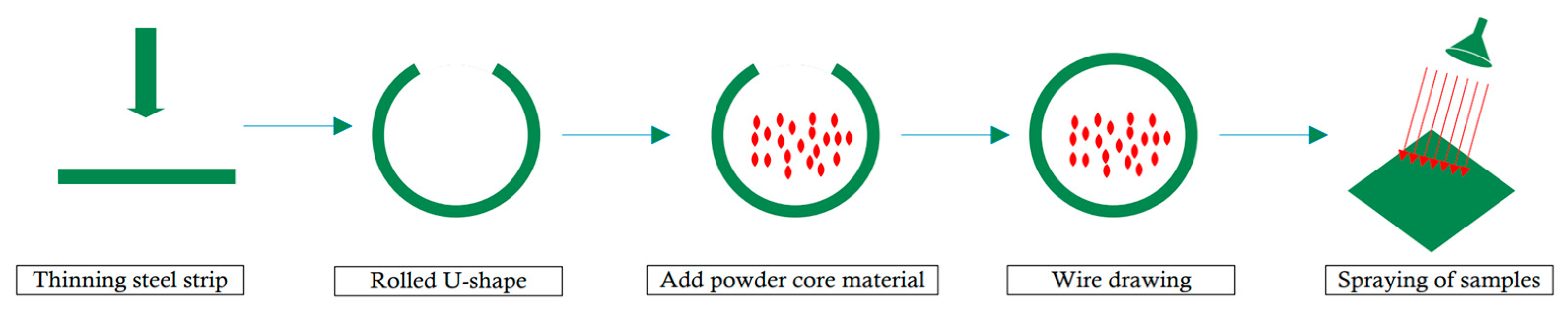
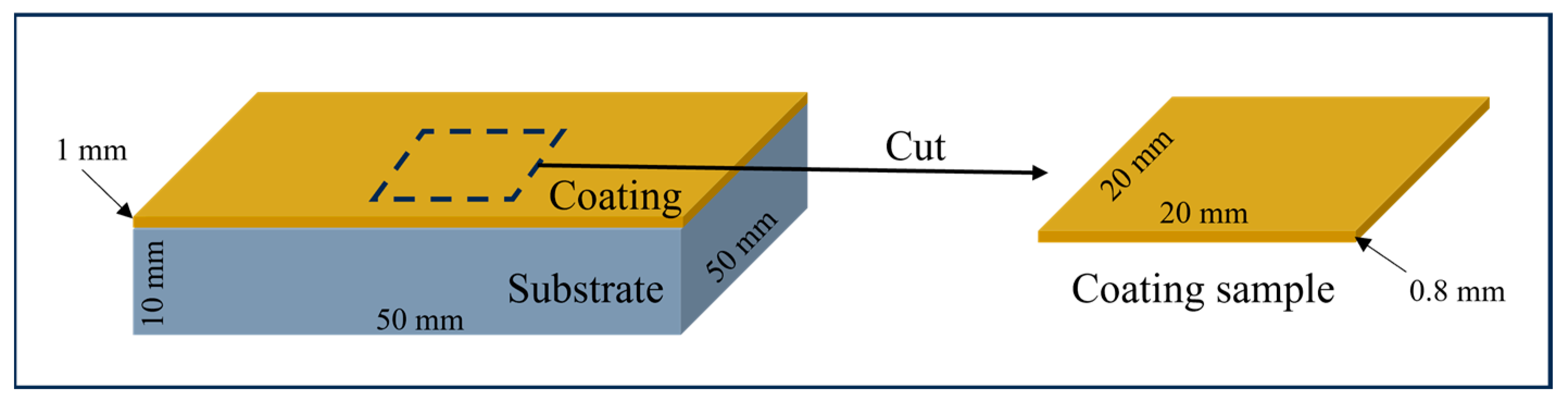
2. Materials and Methods

The present study involved the fabrication of 430 stainless steel strip cored wires with a thickness of 0.5 mm and a width of 12 mm, which were cored with a mixture of Fe, Mn, Cr, Si, and TiC ranging in granularity from 80 to 100 mesh. The filler was a mixture of 99.9% pure metal and metallic compound powder, and the mass share of the filler in the whole powder core wire material was about 35 wt.%. Table 1 lists the proportions of the elements in the cored wires; Table 2 lists the specific compositions of the 430 steel strips and 45 steels used. Figure 1 briefly shows the process of preparing the coated samples. The substrate used for the spraying experiments was 45 steels with dimensions of 50 mm × 50 mm × 10 mm, and the spraying surface was one of the 50 × 50 mm square areas. A coating of almost 1 mm thickness was then sprayed onto one of the 45 steel surfaces (the 50 × 50 mm area) using an SX-600 supersonic arc spraying system. Before spraying, the specimen underwent ultrasonic acetone cleaning to remove oil residues. Subsequently, sandblasting was performed using a small, environmentally friendly box-type manual sandblasting machine (Shenzhen Baiyao Automatic Sandblasting Equipment Co., Ltd., Shenzhen, China, model 6F6050B, Carestream Health, Inc., Rochester, NY, USA). The sandblasting process parameters included a silicon carbide abrasive with a mesh size of 16, gas pressure ranging from about 0.6 to 0.75 MPa, and a distance between the nozzle and specimen surface varying from approximately 160 to 180 mm. The optimized spray parameters are outlined in Table 3.
The hot corrosion test was conducted by the GB/T 29037-2012 standard [26] titled “Thermal spray protective coating against high-temperature corrosion and oxidation”. The coated sample used for the hot corrosion test was a sheet that was cut from the 45 coated steel substrates. And then the coating was polished into the size of 20 × 20 × 0.8 mm3, ensuring that it consisted solely of an FeMnCrSi/TiC coating without any original substrates of the 45 steels. The coated sample preparation process is shown in Figure 2. During the hot corrosion test, a Na2SO4 + K2SO4-saturated aqueous solution with a 7:3 molar ratio was applied onto the stripped coated specimen’s surface with a salt content ranging between 4 and 6 mg/cm2, which ensured that the whole coated sample was submerged in the solution. Subsequently, the coated specimen underwent drying at 200 °C for two hours using a muffle furnace followed by cooling and weighing on an accurate scale with precision up to 0.01 mg, before being subjected to heat treatment at 900 °C for ten hours within another muffle furnace. After cooling down to room temperature, reweighing took place and was recorded as part of the completion of one cycle of the testing procedures. This cycle included the processes of salt coating, drying, weighing, heat treatment, and reweighing until reaching a cumulative duration of hot molten salt corrosion equaling or exceeding 100 h. Concerning statistics, the hot corrosion test was carried out five times. The surface morphology and energy spectrum before and after hot corrosion were analyzed using a Zeiss Sigma 300 field emission scanning electron microscope (FESEM) (ZEISS, Oberkochen, Germany). A physical-phase analysis was conducted with a Rigaku D/MAX 2500 V X-ray diffractometer (Rigaku Corporation, Tokyo, Japan), employing a scanning range of 20~80°, a scanning speed of 6 °/min, a tube voltage of 40 kV, and a tube current of 40 mA. Finally, the cross-sectional morphology of the coated samples was observed utilizing a Leica DM2700 metallurgical microscope (Leica, Berlin, Germany).

3. Results

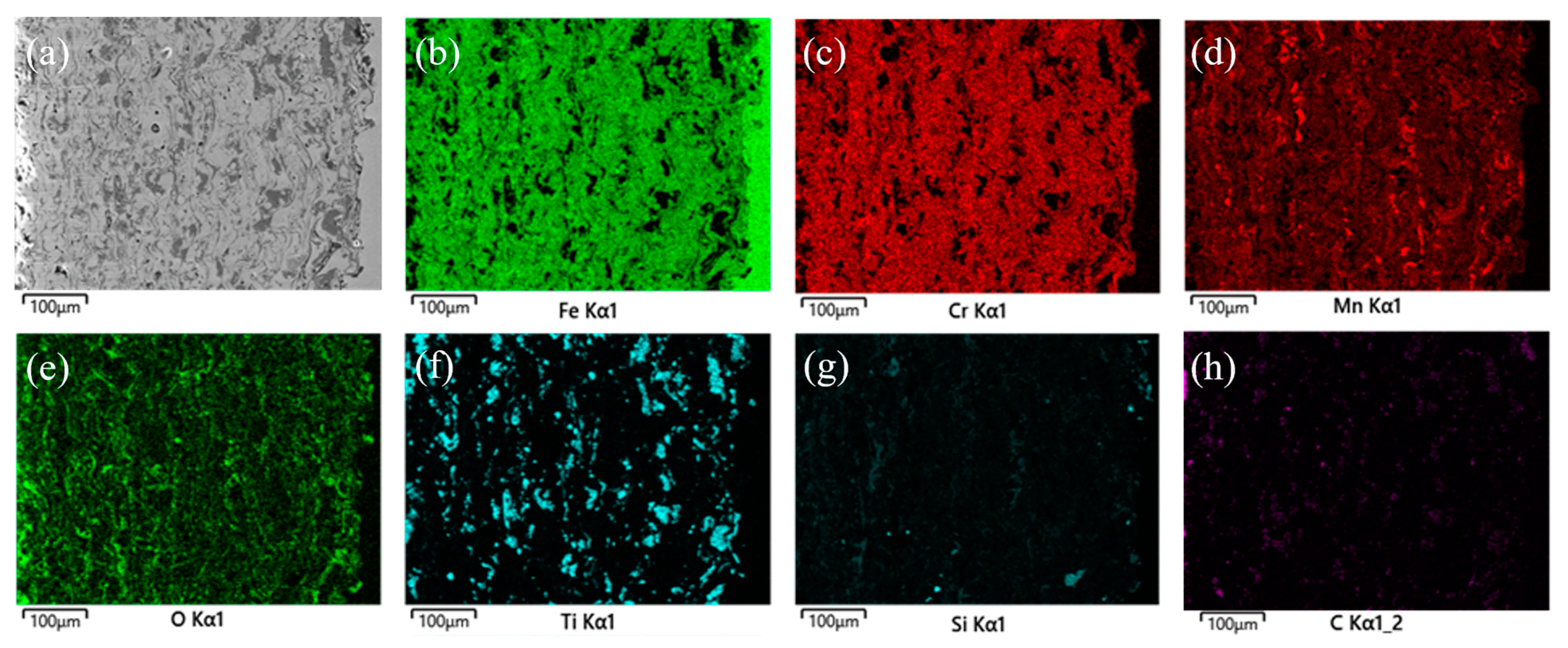
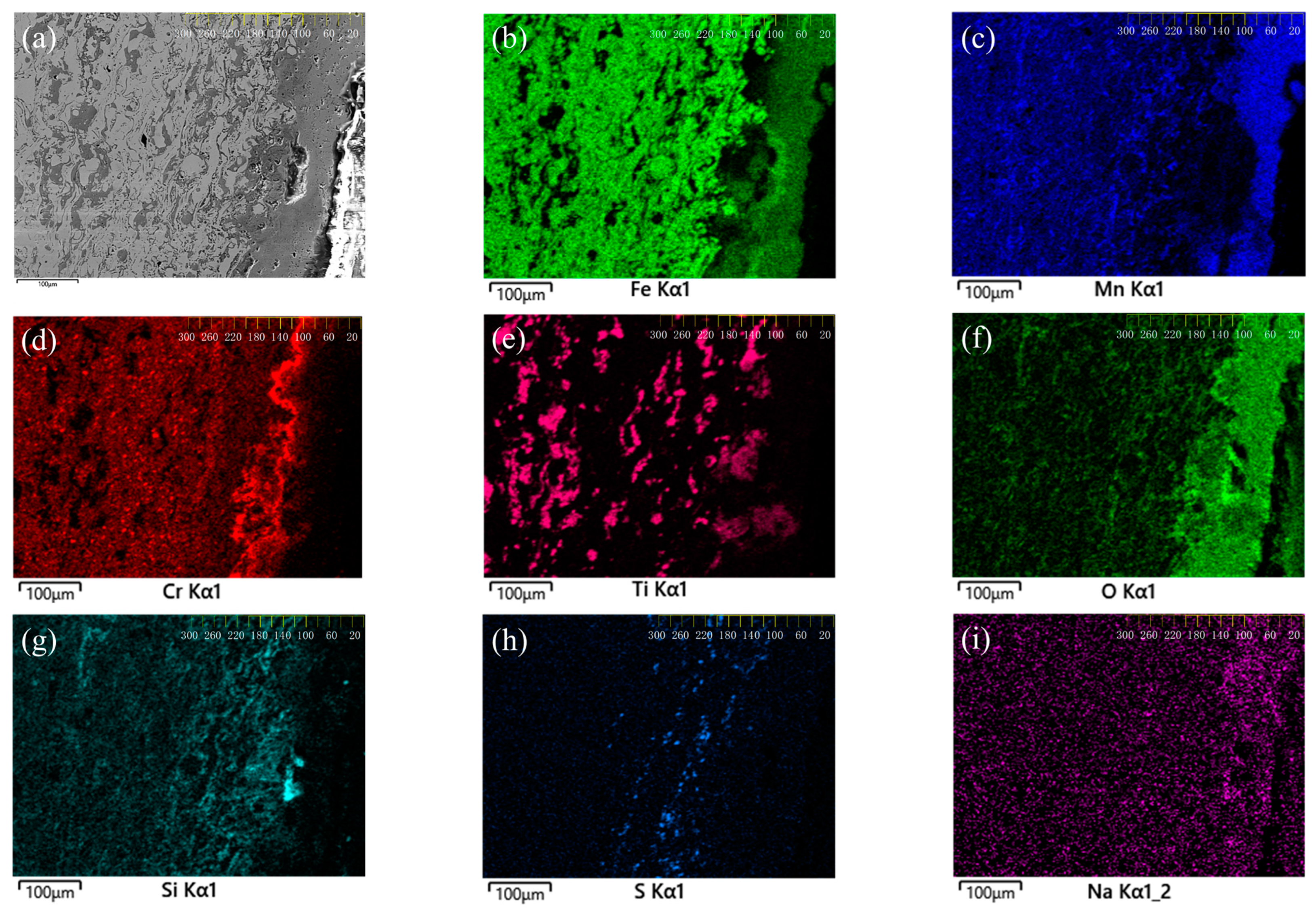
3.1. Microstructure and Phase Analysis of Coating

The SEM images in Figure 3a,b illustrate the initial surface microstructure of the FeMnCrSi/TiC coating. The coated surface is predominantly composed of overlapping flattened flake particles, formed by high-speed droplets of molten powder impinging on the substrate. Due to the substrate’s uneven surface, a sputtering phenomenon occurs, resulting in the generation of a limited number of spherical particles. Figure 3c,d illustrate the cross-sectional SEM image of the coating, revealing a characteristic laminar arrangement in its microstructure. This laminar microstructure is formed during the arc spraying process when high-velocity molten liquid strikes the substrate’s surface, spreading into flakes and rapidly condensing. These flake droplets stack on top of each other, forming a distinctive ripple-layer microstructure.
Despite the overall uniform and dense microscopic morphology of the coating, a small number of pores and microcracks are present, particularly at the coating–substrate interface. This is likely due to the limited mobility of oxide and unfused particles at the interface, resulting in a suboptimal mechanical bond between the coating and the substrate. Using Image Pro Plus 6.0 image processing software, the coating porosity is calculated by randomly selecting five SEM images of its section, with specific values presented in Table 4. The FeMnCrSi/TiC coatings exhibit an average porosity of less than 5%, indicating successful application of process parameters during spraying, effective flattening of droplet particles upon impact with the substrate, and close particle bonding.
Figure 3d displays distinct variations in the deposition degree within the coating, primarily comprising two regions—a grey-white metallic crystalline phase and a dark grey oxide phase. The EDS energy spectrum analysis of points A and B in Figure 3d, as detailed in Table 5, reveals that the metallic crystalline phase at point A mainly consists of Fe, Mn, Cr, Si, C, and other elements, with notably low levels of Ti. This suggests an absence of hard TiC particles within the metallic crystalline phase. Conversely, the oxide phase at point B has a higher oxygen content and primarily consists of Ti, C, Mn, O, and Si, along with traces of Fe and Cr elements.
To gain a more comprehensive understanding of the elemental distribution within the coating, a scanning electron microscopy–energy dispersive spectroscopy (SEM-EDS) analysis of elemental distribution scanning was conducted on the cross-section of the coating. The results of this investigation are presented in Figure 4. It is observed that Fe and Cr exhibit homogeneity within the grey-white metallic matrix phase, while being noticeable in the dark oxidation phase. Conversely, the elements Mn, Si, C, and O are predominantly concentrated within this dark oxidation phase. Furthermore, the Ti elements primarily manifest in the dark-grey oxide phase.
This observed distribution may be a consequence of the rapid solidification of the molten droplets during the arc spraying process. Considering that TiC has an exceptionally high melting point of 3140 °C, significantly higher than that of Fe (1538 °C) and Cr (1857 °C), Fe and Cr elements are difficult to combine with TiC particles.
The X-ray Diffraction (XRD) analysis conducted on the surface of the FeMnCrSi/TiC coating is presented in Figure 5. The analysis reveals that the primary constituents of the coating consist of an Fe-based solid solution α-Fe (body-centered cubic, BCC), β-Fe (face-centered cubic, FCC), and TiC particles. These findings are consistent with the previous EDS energy spectrum analysis and elemental surface distribution analysis. The presence of a solid-solution structure potentially enhances both the hardness and phase stability of the material. The formation of this structure can be attributed to the high mixing entropy of the components designed for this coating material, which facilitates the rapid generation of a stable solid-solution structure [27,28].

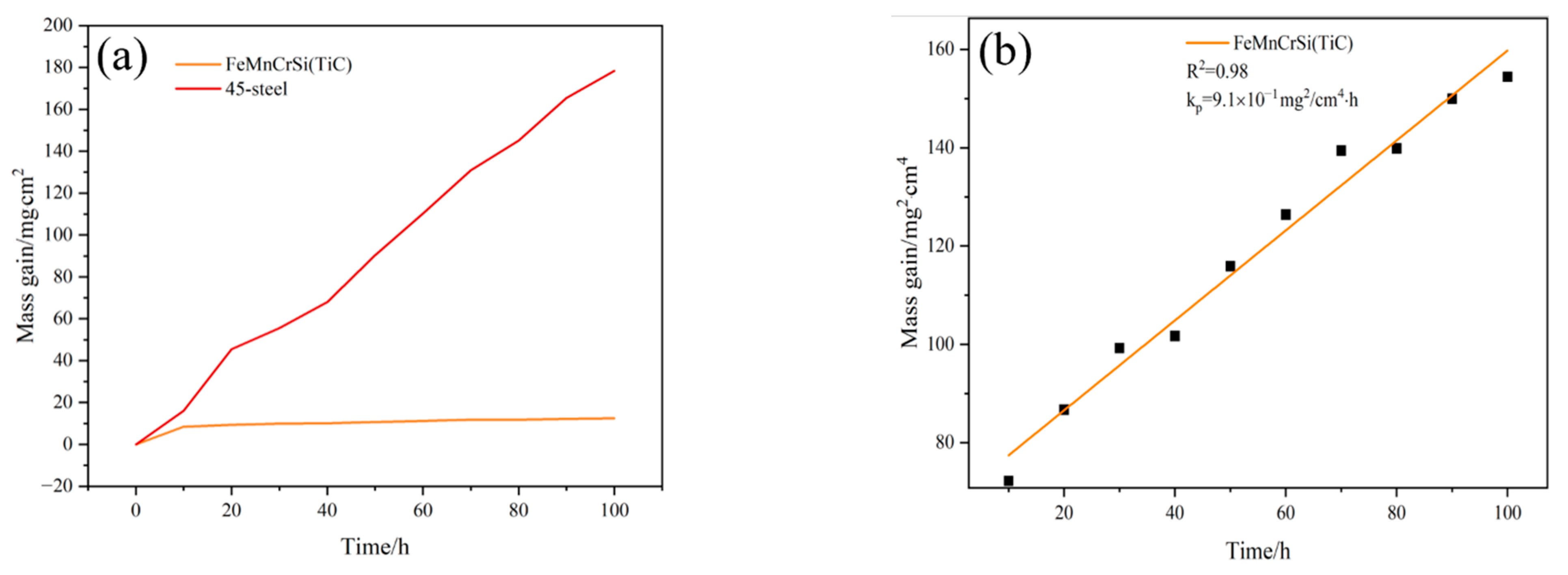
3.2. Hot Corrosion Kinetic Analysis

The changes in unit weight (mg/cm2) of the FeMnCrSi/TiC coating and 45 steel samples during the hot corrosion process are shown in Figure 6a. After 100 h of hot corrosion, the FeMnCrSi/TiC coating and 45 steels exhibited weight gains of 12.43 mg/cm2, while the 45 steels sample showed a weight gain of 178.4 mg/cm2, indicating the superior corrosion resistance of the FeMnCrSi/TiC coating. Additionally, a significant reduction and stabilization in the weight gain rate of the FeMnCrSi/TiC coating were observed at 10 h, suggesting the formation of a protective oxide film on its surface that reduces oxidation and corrosion reaction rates. Figure 6b demonstrates an excellent linear relationship between the squared weight gain variation (ΔM/h)2 for the FeMnCrSi/TiC coating material and the thermal corrosion time. The calculated parabolic rate constant (kp = 9.1 × 10⁻¹ mg2/cm4·h) and degree of fit (R2 = 0.98) indicate that this coating material follows parabolic law kinetics during hot corrosion.

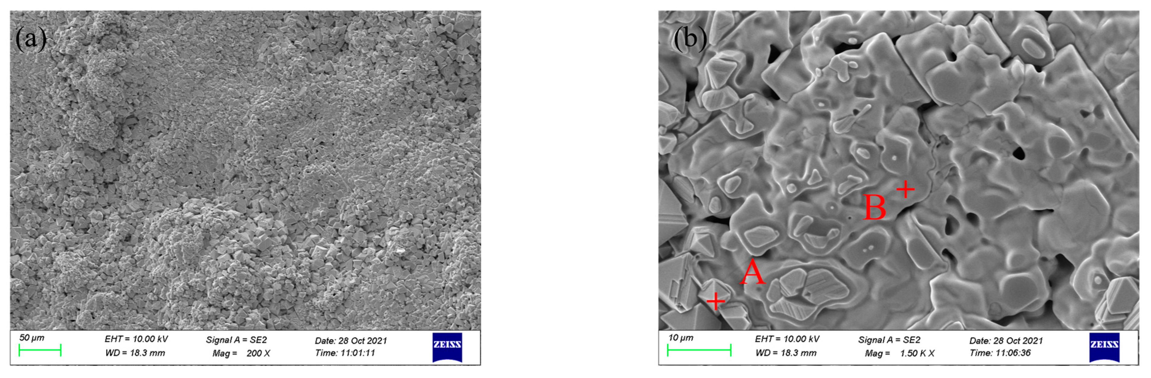
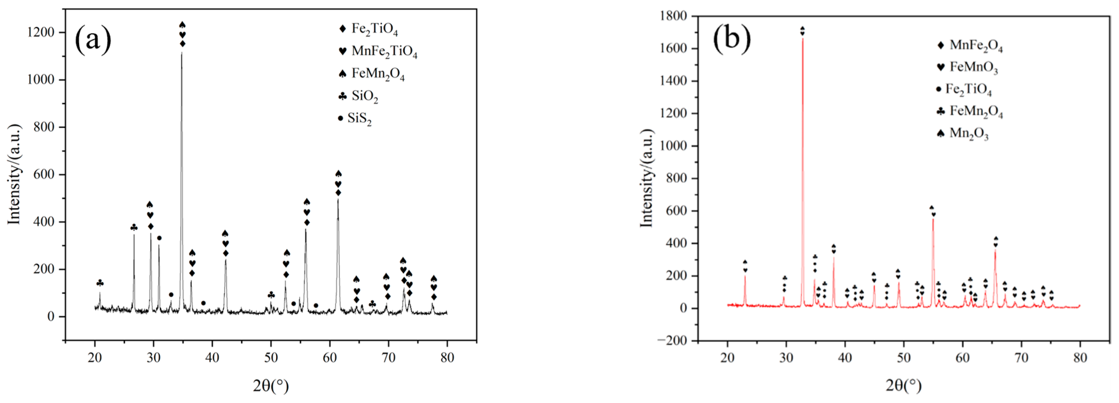
3.3. Surface Morphology and Phase Analysis of Coating after Hot Corrosion

The surface morphology of the FeMnCrSi/TiC coating after 10 h of hot corrosion is illustrated in Figure 7a,b. The coating surface exhibits a granular accumulation of spinel, interspersed with occasional cracks and pores among the corrosion products. Additionally, some particles exhibit a mushy film enveloping their surfaces and cracks. An energy spectrum analysis of points A and B, which exhibit distinct morphologies, as shown in Figure 7b, is detailed in Table 6. Granular oxidation products at point A primarily consist of Fe, Mn, Cr, and O elements, while the mushy films at point B comprise Fe, Mn, Cr, O, and Ti elements. XRD analysis (Figure 8a) reveals that point A predominantly produces FeMn2O3, and point B, with a higher Ti element content than point A, is presumed to generate two kinds of oxides, MnFe2TiO4 and Fe2TiO4. Figure 7c,d depict the morphology of the FeMnCrSi/TiC coating after 100 h of hot corrosion. The oxide layer’s structure remains intact and free of spalling or cracking. The grain size of certain granular corrosion products is significantly increased and the coverage area of the paste-like film is expanded, leading to a reduction in the number of cracks and pores on the coating surface. These observations suggest that the presence of the paste-like film enhances the coating’s corrosion resistance. The EDS analysis of points C and D in Figure 7d (Table 6) reveals that point C primarily contains Fe, Mn, Cr, O, etc., while point D mainly comprises Fe, Mn, Cr, O, Ti, etc. Further examination using XRD, as depicted in Figure 8b, suggests that the granular oxide at point C is predominantly Mn2O3, while the mushy film oxide at point D contains FeMn2O3, Fe2TiO4, MnFe2O4, and other oxides.
The transformation of the primary phase In the oxide film surface could be correlated with the rapid diffusion of Mn elements within the surface oxide layer [29]. Initially, oxidation on the coating surface generates Fe and Mn oxides. As the oxide layer thickens, the rapid diffusion of Mn towards the surface triggers the formation of Mn2O3 particles, which preferentially nucleate in the voids of the oxide layer. This reduces the activity of O2 within the overall oxide layer and promotes the generation of stable Cr2O3 oxides at the oxide layer/metal interface. The comparison of the elemental content at points C and D with that at points A and B (Table 6) reveals an increase in the O content. This finding suggests an exacerbation of coating oxidation during thermal corrosion, spanning from 10 to 100 h. The TiC particles in the coating undergo decarburization reactions at high temperatures, leading to the continuous diffusion of the internal C element to the surface and thereby elevating the surface C elemental content [30,31]. Concurrently, an increase in the thickness of the coating oxide layer is accompanied by a decline in the Cr diffusion rate within the oxide layer [32]. Simultaneously, the reduction in the oxygen partial pressure within the coating stimulates the formation of a more stable oxide layer like the Cr2O3 layer, on the inner side of the oxide layer, thereby reducing the surface Cr content accordingly.

3.4. Cross-Sectional Morphology and Phase Analysis of Coating after Hot Corrosion

The cross-sectional SEM-EDS elemental distribution of the FeMnCrSi/TiC coating after 100 h of hot corrosion is presented in Figure 9. The color differentiation within the figure represents the distribution of each element in the coating. After 100 h of hot corrosion, the internal microstructure of the coating has undergone considerable modifications compared to its initial state. Notably, an oxide layer, approximately 100 μm thick, has formed on the coating surface, primarily composed of Fe, Mn, and Cr. This layer exhibits a layered band structure, with a pronounced enrichment of Cr elements on the inner side of the oxide layer, as depicted in Figure 9d.
Both Mn and Cr elements tend to diffuse into the oxide layer, which results in the formation of a region at the oxide layer/metal interface that is enriched in Fe elements and has reduced Mn and Cr content. To further explore the formation mechanism of the oxide layer/metal interface, the surface of the corroded coated sample was thinned. Initially, the same sample was thinned to approximately 100 μm (reaching the inner side of the oxide layer) for XRD inspection, followed by thinning to about 140 μm (reaching the unoxidized layer) for further XRD inspection. The thickness of the sample was measured using image analysis, and the results are shown in Figure 10. The outer side of the oxide layer predominantly consists of FeMnO3 and Mn2O3, which are oxides of Fe and Mn elements. Conversely, a dense Cr2O3 film deposits to form the inner side of the oxide layer. This film impedes ion exchange during oxidative corrosion, thereby bolstering the anti-oxidation corrosion resistance of the Fe-based material [33]. Fe becomes the principal element at the metal/oxide layer interface, where Cr and Mn are deficient. As illustrated in Figure 9b, this region predominantly comprises a BCC solid solution of Fe, with minor amounts of Fe2TiO4 and TiC. Previous research [21,34] indicates that Mn can act as a stabilizer for the FCC phase, and its substantial depletion triggers the transformation of the coating from a dual-phase structure to a single BCC phase. Figure 9g distinctly indicates a degree of Si element enrichment in this region. According to Huntz et al. [35], Si serves as a stabilizer of the BCC structure of Fe, reducing the oxidation rate of Fe without significant loss during oxidation. This effect partially compensates for the voids created due to the extensive diffusion of Mn.
Figure 9h reveals that the S element traverses the oxide layer and infiltrates the coating interior. It reacts with Cr and Fe elements in the sulfidation and oxidation processes, generating loosely structured, non-protective sulfides such as CrS and FeS. This indicates that the coating undergoes a hot corrosion reaction. As the reaction proceeds, the initially formed sulfides undergo decomposition. The generated S2− can form new sulfides along the grain boundaries or diffuse into the grain interior as a solid solution [36,37].

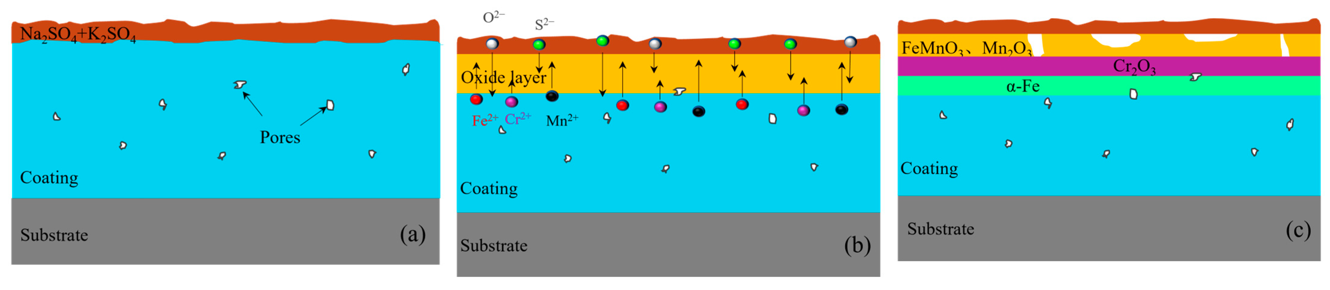
4. Discussion of Hot Corrosion Behavior

The findings of this study reveal that the FeMnCrSi/TiC coating experiences a hot corrosion reaction at 900 °C under molten salt conditions. A dense Cr2O3 layer forms on the inner side of the Mn-rich oxide layer, and concurrently, an Mn-deficient zone, primarily composed of an Fe-based BCC solid solution, emerges at the metal/oxide interface. This structure equips the coating with the ability to safeguard the substrate under high-temperature salt corrosion conditions, providing robust resistance to hot corrosion. The high-temperature hot corrosion process of the coating consists of two primary stages (illustrated in Figure 11): the initial stage and the developed stage.
During the initial stage of hot corrosion, S2− and O2− are generated through the decomposition of the molten salt medium, leading to the sulfidation and oxidation of Fe, Cr, and Mn in the coating. Selective oxidation of Mn and Fe elements [38,39] and the high diffusion rate of Mn in both the coating metal and the oxide layer [40,41] facilitate the preferential formation of FeMn2O3, MnFe2O4, and other Fe-Mn spinel products on the coating’s surface. Furthermore, as the oxide layer continuously thickens under the deposited sulfate, the partial pressure of oxygen is reduced, which weakens the oxidation reaction of the Fe and Mn elements, favoring the formation of oxides of the Cr elements. The Mn element diffuses more rapidly than Cr, leading to the absence of Mn at the interface, which in turn forms a protective and more continuous Cr2O3 layer. Throughout this stage, the ongoing decrease in O2 movement at the oxide/molten salt interface enhance the activity of S. According to the Rapp–Goto criterion [42,43], this establishes a negative solubility gradient at the oxide/molten salt interface.
The S element from the oxide layer diffuses into the coating interior and generates sulfides beneath the oxide film. Simultaneously, the alkalinity of the sulfate augments, leading to alkaline melting at the oxide/molten salt interface, which results in the formation of structurally loose oxides. The molten salt layer can migrate to the alloy’s surface through the accessible oxide layer, persistently degrading the inner Cr2O3 film and accelerating the coating’s corrosion.
At a temperature of 900 °C, the 70% Na2SO4 + 30% K2SO4 mixed salt corrosion medium reaches a molten state, and the thermodynamic equilibrium reaction proceeds as follows:
2 N a 2 S O 4 = 2 N a 2 O + S 2 + 3 O 2
O 2 + 4 e = 2 O 2
S 2 + 4 e = 2 S 2
In the initial stage:
M 2 + + O 2 = M O
2 M 3 + + 3 O 2 = M 2 O 3
M + M O = M · M O
M + M 2 O 3 = M · M 2 O 3
M 2 + + S 2 = M S
2 M 3 + + 3 S 2 = M 2 S 3
In the developed stage:
M + M O = M · M O
2 M 3 + + 3 O 2 = M 2 O 3
M + M S = M · M S
M + M 2 S 3 = M · M 2 S 3
M · M S + 1 2 O 2 = M O + M S
2 M · M 2 S 3 + 3 2 O 2 = M 2 O 3 + 2 M 2 S 3
N a 2 S O 4 + 3 M S = 4 S + 3 M O + N a 2 O
N a 2 S O 4 + M 2 S 3 = S + M 2 O 3 + N a 2 O
As the reaction proceeds, the developed stage of hot corrosion is reached, characterized by the exacerbation of oxidation and sulfidation reactions. The high-temperature molten salt medium fosters the decomposition of sulfur and metal cations, which readily react with the oxygen in the system, thereby accelerating the oxidation process of surface Mn and Cr elements.
Compared to Cr, Mn exhibits preferential oxidation and a higher diffusion rate [44], triggering the preferential formation of Mn-deficient regions beneath the oxide layer. This promotes the transformation of the coated metal from an FCC + BCC dual phase to a BCC single phase. With the formation of the Mn-deficient region, the partial pressure of O decreases, favoring the formation of a stable Cr2O3 phase. Simultaneously, owing to the high diffusivity of Cr in BCC [20,45], Cr near the oxide layer continuously migrates to the oxide layer. This results in the Mn-deficient region rapidly becoming Cr deficient, with Cr enriched at the metal/oxide interface to form a continuous, dense Cr2O3 layer with O [1,33] and reducing the rate of oxidative corrosion. Furthermore, the Cr cations in the coating have a stronger oxygen affinity than the cations of Fe and Mn. They displace the Fe and Mn ions in the Cr2O3 layer, forming localized iron- and manganese-depleted bands (Figure 9b,c). This reduces their content in the Cr2O3 layer and enhances the oxidation corrosion resistance of the coating.

5. Conclusions

(1) After high-velocity arc spraying, the FeMnCrSi/TiC wire generates a wavy, layer-like coating on the substrate’s surface, characterized by a uniform and dense microstructure. The primary metal phases are α-Fe (BCC) solid solutions, which are formed by Fe, Mn, Cr, Si, C, and other elements. Additionally, the coating contains minor amounts of β-Fe (FCC) solid-solution phase and unmelted TiC particles.
(2) The FeMnCrSi/TiC coating, when exposed to molten salt conditions at 900 °C, experiences a high-temperature hot corrosion reaction triggered by the selective oxidation of Mn. This results in a significant increase in coating mass in a relatively short period, with the subsequent weight gain curve adhering to the parabolic law. This indicates that the coating exhibits robust corrosion resistance under these conditions. As the diffusion of the Mn and Cr elements persists, the lower part of the oxide layer becomes depleted of these elements, leading to the transformation of the coating metal from an FCC + BCC dual phase to an α-Fe (BCC) monophase. The rapid growth of the Mn-rich oxide layer reduces the activity of O2 and prompts the formation of a dense Cr2O3 layer at the oxidation layer/metal interface. This structure grants the coating with the capability to protect the substrate from high-temperature molten salt corrosion.

Author Contributions

X.T.: Conceptualization, Data curation, Validation, Visualization, Writing—Original draft. L.L.: Resources, Formal Analysis, Methodology. Z.H.: Data curation, Investigation. J.Z. (Jieji Zhou): Software, Investigation. Y.Q.: Methodology, Visualization. S.Z.: Investigation, Visualization. D.L.: Software, Methodology. Z.X.: Funding acquisition, Project administration, Writing—Original draft, Writing—Review and editing, Supervision. J.Z. (Jianmin Zeng): Project administration, Resources, Supervision. H.T.: Resources, Supervision. Y.W.: Formal Analysis, Visualization. All authors have read and agreed to the published version of the manuscript.

Funding

This project was supported by the National Natural Science Foundation of China (51961008), the Regional Joint Fund of the National Natural Science Foundation of China (U20A20276), and the Guangxi Science and Technology Major Program (No. AA23073019-1 and AA23073017-1).

Data Availability Statement

The raw data supporting the conclusions of this article will be made available by the authors on request.

Conflicts of Interest

The authors declare no conflicts of interest.

References

  1. Prashar, G.; Vasudev, H. Hot corrosion behavior of super alloys. Mater. Today Proc. 2020, 26, 1131–1135. [Google Scholar] [CrossRef]
  2. Hou, B.; Li, X.; Ma, X.; Du, C.; Zhang, D.; Zheng, M.; Xu, W.; Lu, D.; Ma, F. The cost of corrosion in China. npj Mater. Degrad. 2017, 1, 4. [Google Scholar] [CrossRef]
  3. Hu, S.; Finklea, H.; Liu, X. A review on molten sulfate salts induced hot corrosion. J. Mater. Sci. Technol. 2021, 90, 243–254. [Google Scholar] [CrossRef]
  4. Muthu, S.; Arivarasu, M.; Arivazhagan, N. Investigation of hot corrosion resistance of bare and Ni-20% Cr coated superalloy 825 to Na2SO4-60% V2O5 environment at 900 °C. Procedia Struct. Integr. 2019, 14, 290–303. [Google Scholar] [CrossRef]
  5. Löbel, M.; Lindner, T.; Grimm, M.; Rymer, L.-M.; Lampke, T. Influence of Aluminum and Molybdenum on the Microstructure and Corrosion Behavior of Thermally Sprayed High-Entropy Alloy Coatings. J. Therm. Spray Technol. 2022, 31, 1366–1374. [Google Scholar] [CrossRef]
  6. Patel, N.S.; Pavlík, V.; Boča, M. High-temperature corrosion behavior of superalloys in molten salts—A review. Crit. Rev. Solid State Mater. Sci. 2017, 42, 83–97. [Google Scholar] [CrossRef]
  7. Yang, L.; Ouyang, J.; Wang, Z.-M.; Song, G.-L. The Early-Stage Propagation of Localized Corrosion of a Sintered NdFeB Alloy in Aqueous Environments. J. Mater. Eng. Perform. 2023. [Google Scholar] [CrossRef]
  8. Cheng, J.; Wu, Y.; Shen, W.; Hong, S.; Qiao, L.; Wang, Y. A study on hot corrosion performance of high velocity arc-sprayed FeCrNiAlMnB/Cr3C2 coating exposed to Na2SO4 + K2SO4 and Na2SO4 + NaCl. Surf. Coat. Technol. 2020, 397, 126015. [Google Scholar] [CrossRef]
  9. Prashar, G.; Vasudev, H. Application of thermal spraying techniques used for the surface protection of boiler tubes in power plants: Thermal spraying to combat hot corrosion. In Advanced Surface Coating Techniques for Modern Industrial Applications; IGI Global: Hershey, PA, USA, 2021; pp. 112–134. [Google Scholar]
  10. Liu, C.; Lu, H.; Qin, E.; Ye, L.; Wu, S. The FeCr-based coating by on-site twin-wire arc spraying for proactive maintenance of power plant components. J. Therm. Spray Technol. 2021, 30, 959–967. [Google Scholar] [CrossRef]
  11. Galedari, S.A.; Mahdavi, A.; Azarmi, F.; Huang, Y.; McDonald, A. A comprehensive review of corrosion resistance of thermally-sprayed and thermally-diffused protective coatings on steel structures. J. Therm. Spray Technol. 2019, 28, 645–677. [Google Scholar] [CrossRef]
  12. Tian, H.; Wang, C.; Guo, M.; Tang, Z.; Wei, S.; Xu, B. Study of the frictional-wear performance and abrasion resistance mechanism of a high-speed arc-sprayed FeNiCrAl coating. Surf. Coat. Technol. 2019, 370, 320–330. [Google Scholar] [CrossRef]
  13. Li, R.; He, D.; Zhou, Z.; Wang, Z.; Song, X. Wear and high temperature oxidation behaviour of wire arc sprayed iron based coatings. Surf. Eng. 2014, 30, 784–790. [Google Scholar] [CrossRef]
  14. Luo, L.; Liu, S.; Li, J.; Yucheng, W. Oxidation behavior of arc-sprayed FeMnCrAl/Cr3C2–Ni9Al coatings deposited on low-carbon steel substrates. Surf. Coat. Technol. 2011, 205, 3411–3415. [Google Scholar] [CrossRef]
  15. Abdallah, I.; Kim, T.; Wu, X.; Bailly-Salins, L.; Elbakhshwan, M.; Carroll, M.; Tonks, M.R.; Perepezko, J.H.; Couet, A. Oxidation kinetics and microstructure evolution of high Mn stainless-steel alloy in CO2 at 700 °C. Corros. Sci. 2022, 195, 110013. [Google Scholar] [CrossRef]
  16. Ndumia, J.N.; Kang, M.; Gbenontin, B.V.; Lin, J.; Nyambura, S.M. A review on the wear, corrosion and high-temperature resistant properties of wire arc-sprayed Fe-based coatings. Nanomaterials 2021, 11, 2527. [Google Scholar] [CrossRef]
  17. Luo, L.-M.; Liu, S.-G.; Jia, Y.; Juan, L.; Jian, L. Effect of Al content on high temperature erosion properties of arc-sprayed FeMnCrAl/Cr3C2 coatings. Trans. Nonferrous Met. Soc. China 2010, 20, 201–206. [Google Scholar] [CrossRef]
  18. Boulos, M.I.; Fauchais, P.L.; Heberlein, J.V.R. Industrial Applications of Thermal Spray Technology. In Thermal Spray Fundamentals: From Powder to Part; Boulos, M.I., Fauchais, P.L., Heberlein, J.V.R., Eds.; Springer International Publishing: Cham, Switzerland, 2021; pp. 997–1096. [Google Scholar]
  19. Mahajan, S.; Chhibber, R. Hot corrosion studies of boiler steels exposed to different molten salt mixtures at 950 °C. Eng. Fail. Anal. 2019, 99, 210–224. [Google Scholar] [CrossRef]
  20. Silva, R.; Vacchi, G.; Santos, I.; de Sousa Malafaia, A.; Kugelmeier, C.; Mendes Filho, A.; Pascal, C.; Sordi, V.; Rovere, C. Insights into high-temperature oxidation of Fe-Mn-Si-Cr-Ni shape memory stainless steels and its relationship to alloy chemical composition. Corros. Sci. 2020, 163, 108269. [Google Scholar] [CrossRef]
  21. da Cruz Passos, J.G.; Rabelo, L.F.P.; de Freitas, B.X.; da Silva, R.; Della Rovere, C.A.; de Sousa Malafaia, A.M. Effects of silicon and manganese content on the oxidation behavior of FeMnSiCrNi alloys and the correlation between Mn-depleted zone, surface roughness and oxidation resistance. Corros. Sci. 2021, 191, 109724. [Google Scholar] [CrossRef]
  22. de Sousa Malafaia, A.M.; Latu-Romain, L.; Wouters, Y. Initial stages of FeMnSiCrNi shape memory stainless steels oxidation mechanism at 800 °C. Corros. Sci. 2021, 181, 109255. [Google Scholar] [CrossRef]
  23. Matthews, S.; James, B.; Hyland, M. High temperature erosion–oxidation of Cr3C2–NiCr thermal spray coatings under simulated turbine conditions. Corros. Sci. 2013, 70, 203–211. [Google Scholar] [CrossRef]
  24. Chen, H.; Lu, Y.; Sun, Y.; Wei, Y.; Wang, X.; Liu, D. Coarse TiC particles reinforced H13 steel matrix composites produced by laser cladding. Surf. Coat. Technol. 2020, 395, 125867. [Google Scholar] [CrossRef]
  25. Zhu, H.; Ouyang, M.; Hu, J.; Zhang, J.; Qiu, C. Design and development of TiC-reinforced 410 martensitic stainless steel coatings fabricated by laser cladding. Ceram. Int. 2021, 47, 12505–12513. [Google Scholar] [CrossRef]
  26. GB/T 29037-2012; Thermal Spraying—Coatings for Protection against Corrosion and Oxidation at Elevated Temperatures. The Standardization Administration of the People’s Republic of China: Beijing, China, 2013.
  27. Sun, S.; Zhang, Y.; Xue, Z.; Lin, J.; Chen, X. Deformation Mechanism in Fe61Mn18S11Cr10 Medium Entropy Alloy Under Different Strain Rates. Acta Metall. Sin. (Engl. Lett.) 2021, 34, 1109–1119. [Google Scholar] [CrossRef]
  28. Zhang, R.; Zhao, S.; Ding, J.; Chong, Y.; Jia, T.; Ophus, C.; Asta, M.; Ritchie, R.O.; Minor, A.M. Short-range order and its impact on the CrCoNi medium-entropy alloy. Nature 2020, 581, 283–287. [Google Scholar] [CrossRef]
  29. Su, M.; Zhao, J.; Gu, C. Investigation of the high-temperature oxidation behavior of Fe-14Cr-9Mn-2.5Ni austenitic stainless steel in N2-21 vol%O2 environment. Corros. Sci. 2023, 220, 111294. [Google Scholar] [CrossRef]
  30. Katranidis, V.; Gu, S.; Cox, D.C.; Whiting, M.J.; Kamnis, S. FIB-SEM sectioning study of decarburization products in the microstructure of HVOF-sprayed WC-Co coatings. J. Therm. Spray Technol. 2018, 27, 898–908. [Google Scholar] [CrossRef]
  31. Du, J.; Li, F.; Li, Y.; Lu, H.; Qi, X.; Yang, B.; Li, C.; Yu, P.; Cao, Y. High temperature oxidation behavior and interface diffusion of Cr3C2-NiCrCoMo/nano-CeO2 composite coatings. J. Alloys Compd. 2022, 905, 164177. [Google Scholar] [CrossRef]
  32. Chandra-ambhorn, S.; Saranyachot, P.; Thublaor, T. High temperature oxidation behaviour of Fe–15.7 wt.% Cr–8.5 wt.% Mn in oxygen without and with water vapour at 700 °C. Corros. Sci. 2019, 148, 39–47. [Google Scholar] [CrossRef]
  33. Kumar, S.; Kumar, R. Influence of processing conditions on the properties of thermal sprayed coating: A review. Surf. Eng. 2021, 37, 1339–1372. [Google Scholar] [CrossRef]
  34. Ma, R.; Peng, H.; Wen, Y.; Zhang, L.; Zhao, K. Oxidation behavior of an austenitic stainless FeMnSiCrNi shape memory alloy. Corros. Sci. 2013, 66, 269–277. [Google Scholar] [CrossRef]
  35. Leong, A.; Yang, Q.; McAlpine, S.W.; Short, M.P.; Zhang, J. Oxidation behavior of Fe-Cr-2Si alloys in high temperature steam. Corros. Sci. 2021, 179, 109114. [Google Scholar] [CrossRef]
  36. Chen, Z.; Li, S.; Wu, M.; Pei, Y.; Gong, S.; Zhang, H. Effects of Different surface native pre-oxides on the hot corrosion properties of nickel-based single crystal superalloys. Materials 2020, 13, 5774. [Google Scholar] [CrossRef] [PubMed]
  37. Jin-tao, L.; Yan, L.; Zhen, Y.; Jin-yang, H.; Ming, Z.; Gu, Y. Effect of Sulfur and Chlorine on Fireside Corrosion Behavior of Inconel 740 H Superalloy. High Temp. Mater. Process. 2018, 37, 245–251. [Google Scholar] [CrossRef]
  38. Souza, V.F.d.; Araújo, A.J.; Santos, J.L.d.N.; Rovere, C.A.D.; Malafaia, A.M.d.S. Kinetics oxidation and characterization of cyclically oxidized layers at high temperatures for FeMnSiCrNiCe and FeSiCrNi alloys. Mater. Res. 2017, 20, 365–373. [Google Scholar] [CrossRef]
  39. Lehmusto, J.; Sattari, M.; Halvarsson, M.; Hupa, L. Should the oxygen source be considered in the initiation of KCl-induced high-temperature corrosion? Corros. Sci. 2021, 183, 109332. [Google Scholar] [CrossRef]
  40. Inoue, Y.; Hiraide, N.; Hayashi, A.; Ushioda, K. Effect of Mn addition on scale structure of Nb containing ferritic stainless steel. ISIJ Int. 2018, 58, 1850–1859. [Google Scholar] [CrossRef]
  41. Zhang, H.; Wu, J.; Liu, X.; Baker, A. Studies on elements diffusion of Mn/Co coated ferritic stainless steel for solid oxide fuel cell interconnects application. Int. J. Hydrogen Energy 2013, 38, 5075–5083. [Google Scholar] [CrossRef]
  42. Xu, Z.; Zhang, H.; Du, X.; He, Y.; Luo, H.; Song, G.; Mao, L.; Zhou, T.; Wang, L. Corrosion resistance enhancement of CoCrFeMnNi high-entropy alloy fabricated by additive manufacturing. Corros. Sci. 2020, 177, 108954. [Google Scholar] [CrossRef]
  43. Birbilis, N.; Choudhary, S.; Scully, J.R.; Taheri, M.L. A perspective on corrosion of multi-principal element alloys. npj Mater. Degrad. 2021, 5, 14. [Google Scholar] [CrossRef]
  44. Liu, Y.; Zhang, L.; Du, Y.; Yu, D.; Liang, D. Atomic mobilities, uphill diffusion and proeutectic ferrite growth in Fe–Mn–C alloys. Calphad 2009, 33, 614–623. [Google Scholar] [CrossRef]
  45. de Sousa Malafaia, A.M.; Latu-Romain, L.; Wouters, Y. High temperature oxidation resistance improvement in an FeMnSiCrNi alloy by Mn-depletion under vacuum annealing. Mater. Lett. 2019, 241, 164–167. [Google Scholar] [CrossRef]
Figure 1. The process of preparing the coated samples.
Metals 14 00504 g001
Figure 2. The coated sample preparation process.
Metals 14 00504 g002
Figure 3. Surface and cross-sectional morphology of FeMnCrSi/TiC coating. Surface morphology: (a,b); cross-sectional morphology: (c,d).
Metals 14 00504 g003
Figure 4. SEM-EDS element distribution map of FeMnCrSi/TiC coating cross-section: (a) cross-section morphology; (b) Fe element distribution map; (c) Cr element distribution map; (d) Mn element distribution map; (e) O element distribution map; (f) Ti element distribution map; (g) Si element distribution map; (h) C element distribution map.
Metals 14 00504 g004
Figure 5. XRD patterns of FeMnCrSi/TiC coating surface.
Metals 14 00504 g005
Figure 6. Corrosion kinetics of FeMnCrSi/TiC coatings at 900 °C: (a) corrosion weight gain curve; (b) corrosion weight gain squared (ΔM/h)2 curve.
Metals 14 00504 g006
Figure 7. SEM images of FeMnCrSi/TiC coating after 900 °C corrosion for 10 h and 100 h: (a,b) after 10 h corrosion; (c,d) after 100 h corrosion.
Metals 14 00504 g007aMetals 14 00504 g007b
Figure 8. XRD patterns of FeMnCrSi/TiC coatings after hot corrosion at 900 °C for 10 h and 100 h: (a) 10 h; (b) 100 h.
Metals 14 00504 g008
Figure 9. SEM-EDS element distribution of FeMnCrSi/TiC coating after corrosion at 900 °C for 100 h: (a) cross-sectional morphology after corrosion; (b) Fe distribution; (c) Mn distribution; (d) Cr element distribution map; (e) Ti element distribution map; (f) O element distribution map; (g) Si element distribution map; (h) S element distribution map; (i) Na element distribution map.
Metals 14 00504 g009
Figure 10. XRD patterns of the oxide layer formed after the FeMnCrSi/TiC coating was corroded at 900 °C for 100 h after thinning treatment: (a) thinned by 100 μm; (b) thinned by 140 μm.
Metals 14 00504 g010
Figure 11. Diagram of hot corrosion of coating: (a) molten salt state of the coating; (b) initial stage of hot corrosion of the coating; (c) developed stage of hot corrosion of the coating.
Metals 14 00504 g011
Table 1. Composition of core wire materials of powder ratio (wt.%).
FeMnCrSi/TiCTiCMnCrSiFe
5%20%15%11%47%
Table 2. The composition ratio (wt.%) of 403 stainless steel strips and 45 steels.
SteelCrMnSiCPSFe
430 steel strips (Saky Steel, Shanghai, China)16%≤1.00%0.5%≤0.12%≤0.03%≤0.04%Bal.
45 steels≤0.25%0.6%0.25%0.45%≤0.035%≤0.035%Bal.
Table 3. Arc spraying process parameters.
Voltage/VCurrent/AAtomized Air Pressure/MPaSpray Distance/mm
30~35220~2400.65~0.75160~180
Table 4. The porosity of FeMnCrSi/TiC coating.
CoatingPorosity (%)Average Value (%)
FeMnCrSi/TiC5.554.434.554.944.824.86
Table 5. The phase composition at points A and B of FeMnCrSi/TiC coating.
CoatingPointElement (at%)
FeMnCrSiTiCO
FeMnCrSi/TiCA61.6220.3211.293.950.372.450.01
B0.7911.730.352.0951.887.6025.56
Table 6. EDS analysis results of FeMnCrSi/TiC coating after hot corrosion for 10 h and 100 h (wt.%).
FeMnCrSi/TiCPointElement (wt.%)
FeMnCrSiTiCOSNaK
10 hA33.2939.411.290.310.560.8722.671.52
10 hB35.8438.11.280.482.770.6620.170.66
100 hC31.8736.240.150.231.3629.81
100 hD32.2530.680.130.921.5234.39
Disclaimer/Publisher’s Note: The statements, opinions and data contained in all publications are solely those of the individual author(s) and contributor(s) and not of MDPI and/or the editor(s). MDPI and/or the editor(s) disclaim responsibility for any injury to people or property resulting from any ideas, methods, instructions or products referred to in the content.

