Article

The Effect of Refined Coherent Grain Boundaries on High-Temperature Oxidation Behavior of TiAl-Based Alloys through Cyclic Heat Treatment

School of Materials Science and Engineering, Xi’an Shiyou University, Xi’an 710065, China
*
Author to whom correspondence should be addressed.
Metals 2024, 14(5), 521; https://doi.org/10.3390/met14050521
Submission received: 28 March 2024 / Revised: 23 April 2024 / Accepted: 28 April 2024 / Published: 29 April 2024
(This article belongs to the Special Issue Advances in Lightweight Alloys)

Abstract

:
The grain size of the full lamellae TiAl-based alloy changes from ~400 μm to ~40 μm through the precipitation of metastable structures by cyclic heat treatment. Based on this, two kinds of variant selection processes—coherent metastable γ variants precipitated during the air-cooling process and αs variants precipitated during the holding at a single α phase region process—are identified to promote the formation of refined Type I and Type II coherent grain boundaries. The oxidation tests at 1000 °C for 100 h show that the formation of refined coherent grain boundaries can greatly improve oxidation resistance by inducing the continuous multi-layer protective barrier consisting of (Ti, (Nb, Ta))O2, TiN, and Al(Nb,Ta)2. This protective barrier inhibits the inward diffusion of oxygen and nitrogen.

1. Introduction

Due to their high specific stiffness, good creep properties, and oxidation resistance at high temperatures, cast TiAl-based alloys with low density (3.8~4.3 g/cm3) are important for applications in aerospace and automotive engines to improve fuel economy [1,2,3]. However, the lack of oxidation resistance over 800 °C and the associated embrittlement of γ-TiAl and α2-Ti3Al intermetallic phases could limit the application of TiAl-based alloys [4]. Although the Al content is relatively high, it is difficult to form a protective continuous Al2O3 oxide film in the outermost layer due to the similar thermodynamic activity of TiO2 and Al2O3 and the faster growth velocity of TiO2. Instead, a TiO2 + Al2O3 mixed layer or TiO2 layer is preferred [5,6]. The intrinsic porous structure of rutile TiO2 and the loose structure of TiO2 + Al2O3 are not helpful in improving the oxidation resistance [7,8].
Therefore, numerous methods have been attempted to improve high-temperature oxidation resistance. For micro-alloying elements added in TiAl-based alloys, the addition of Nb [7], Si [4], Ta [6], Mo [5], and Sn [8] has been found to be beneficial in promoting the formation of a strong and continuous oxide Al2O3 layer or other continuous metal-oxide layer. Besides, changes in microstructure, including grain size, can also affect the oxidation behavior of TiAl alloys [9,10,11,12]. The fine full lamellae (FFL) microstructure has been demonstrated to have the best mechanical properties, particularly in terms of tensile ductility at room temperature [13,14,15,16,17]. However, it has been found that the influence of the grain size of the α2 + γ lamellae colony on the oxidation behavior of a TiAl-based alloy presents both positive and negative effects. On the one hand, the grain refinement can introduce more grain boundaries, which provide channels for oxygen or nitrogen diffusion to the substrate and consequently reduce oxidation resistance [9,10]. On the other hand, an increased number of grain boundaries can also facilitate the movement of Al atoms to form a continuous and strong Al2O3 protective layer on the surface, thereby preventing further diffusion of oxygen or nitrogen [18]. Therefore, it is necessary to clearly illustrate whether grain size has a positive or negative effect on the oxidation behavior of TiAl alloys.
In this study, we investigated the effects of grain size and grain boundary structure on the high-temperature oxidation resistance of a TiAl-based alloy by performing isothermal oxidation tests at 1000 °C for 100 h. Surprisingly, our research presents clear evidence that the FFL TiAl alloy has coherent grain boundaries and much better oxidation resistance than the coarse full lamellae (CFL) TiAl alloy. Moreover, the mechanism of oxidation behavior affected by the coherent grain boundaries was discussed in depth.

2. Materials and Methods

The cast γ-TiAl ingot (Ti-48Al-3Nb-2Ta (at.%)) was melted by a consumable electrode arc melting furnace in an argon atmosphere and repeated three times. Then the ingot was hot isostatically pressed (HIP) at 1280 °C/150 MPa for 4 h, followed by homogenization treatment at 1430 °C (above the single α-phase region) for 2 h. A cyclic heat treatment was conducted. One cycle of heat treatment includes heating to 1430 °C for 5 minutes, then cooling to room temperature in the air. After that, heat to 1280 °C (in the α + γ two-phase region) for 4 hours, then cool in the air. After 5 cycles of heat treatment, the samples were heated at 1430 °C for 5 minutes, then cooled in the air for post-processing.
For oxidation tests, 8 mm × 8 mm × 8 mm samples were cut off from the homogenized and cyclic heat treatment samples. Prior to oxidation, samples were mechanically ground by standard SiC papers with different meshes (from 400 to 5000 mesh) to obtain sufficient surface polish. Then, each sample was ultrasonically cleaned in acetone for 20 minutes. To ensure the repeatability and scatter of the experiment, two duplicate specimens of each alloy were measured simultaneously. The high-temperature oxidation tests were performed in a corundum crucible at 1000 °C for 100 h in laboratory air conditioning in a box furnace. The samples were transferred into an oven, with the oven door open at a certain angle to ensure that all surfaces of the samples were in full contact with the air. The weight of each specimen was measured after a particular period (5 h, 15 h, 25 h, 35 h, 50 h, 70 h, and 100 h) using a high-precision (0.001 mg) FA2204B electronic balance (Shandong, China) after being cooled in air for approximately 40 min. Afterward, the crucibles were placed back in the furnace operated at 1000 °C.
The surface phase composition after 100 h of isothermal oxidation was characterized by X-ray diffraction (XRD, D/max-RB) with Cu Kα radiation performed with a 2θ angle of 20° to 90° and a scanning speed of 5°/min. The morphologies of the oxide surface and cross-sectional morphology of the oxide film were observed by SEM using FEI Helios NanoLab G3 (Waltham, MA, USA). It is necessary to ensure that the oxide film in the image is long enough and the oxide film/substrate interface can be clearly seen. The oxide film thicknesses were measured at five different positions at equal intervals. Due to the resolution of EBSD, which is not able to differentiate between the six variants of γ phase, the γ-L10 structure has a tetragonality symmetry (c/a = 1.02) (which is possible using TEM), and the γ variants were indexed as a faced-centered cubic (fcc) crystal. The HRTEM and HAADF images were carried out on a FEI Themis Z double Cs corrector transmission microscope (Waltham, MA, USA) operating at 300 kV.

3. Results

3.1. Microstructure of CFL and FFL Alloys

The schematics of the cyclic heat-treatment route of the as-cast Ti-48Al-3Nb-2Ta (at.%) alloy are illustrated in Figure 1a. A coarse full lamellae (CFL) microstructure with an average grain size of ~400 μm can be observed after homogenization treatment (Figure 1b). Metastable structures: feathery-like structures and massive γ phase are observed embedding in the lamellae colony with different crystal orientations. Previous studies have shown that [19,20] metastable structures are preferred after heat treatment in a single α-phase region and cooling at a relatively high rate. Furthermore, the cooling rate, which needs to promote the formation of metastable structures, is found to be lowered by the addition of heavy elements such as Nb and Ta [21,22]. Therefore, in this study, the feathery-like structures and massive γ phase can be observed after the air cooling condition of the Ti-48Al-3Nb-2Ta alloy. Finally, after five cycles of cyclic heat treatment and post-processing, the primary CFL microstructure is completely different from the fine full lamellae (FFL) microstructure (Figure 1c).
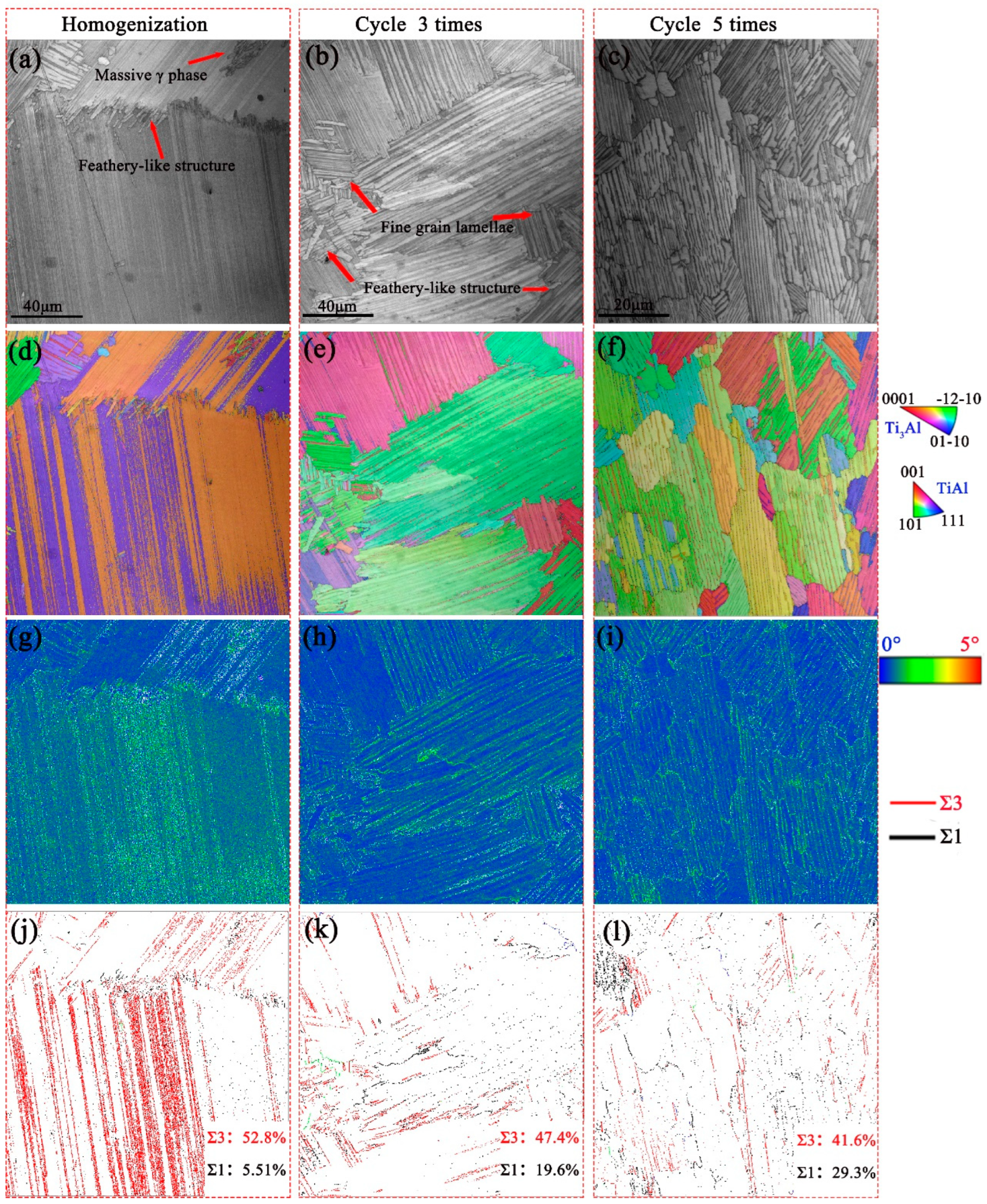
The inverse pole figure (IPF), kernel average misorientation (KAM) maps, grain boundary maps, and misorientation distributions of alloys after cyclic heat treatment with zero, three, and five cycles are shown in Figure 2 to further investigate the characteristics of the refinement of these lamellar colonies. All the samples consist of α2 + γ lamellar colonies. The metastable structure of feathery-like structures and massive γ phase with different grain orientations can be observed when the grain size is large, as shown in Figure 2a,b. After five cyclic heat treatment processes, the coarse microstructure disappears and a fine, fully α2 + γ lamellar microstructure is observed. The grain size was refined from 400 μm to about 40 μm (Figure 2d–f).
Furthermore, during cyclic heat treatment, the structure of the interface also changes, as shown in Figure 2j–l. The lamellar colonies with the following Σ1, Σ3 coincidence site lattice (CSL) boundaries are observed: It can be found that the volume fraction of Σ3 60°< 111 > twin-related boundary decreases from 52.8% to 41.6%, and that of Σ1 boundary increases from 5.51% to 20.3% after five times cyclic heat treatment. It should be noticed that for CFL alloy, the inner lamellar colony mainly consists of Σ3 CSL boundaries, indicating the interfaces between γ/γ lamellae are primarily twin-related interfaces. But the grain boundaries are found to be disordered, large-angle boundaries. For FFL alloy, the majority of grain boundaries are identified as Σ1 and Σ3 coincidence site lattice boundaries. The misorientations after 0° to 5° for 0, 3, and 5 cycles are illustrated by utilizing the KAM maps shown in Figure 2g–i, where the CFL alloy with a metastable structure presented a higher strain than the FFL alloy due to the longtime heat treatment (Figure 2j–l).
Figure 3 shows the enlargement of the local grain orientation information of the microstructure after five cycles. According to the PFs, the Blackburn orientation relationship of {0001}α2//{111}γ between α2 and γ phases can be well-defined. Furthermore, it can be seen that Grain 1 and Grain 2 share the same γ grain that {111}γ1 equal to {111}γ2, but have different α2 grain, that αs1 has 71° misorientation with αs2; for Grain 3 and Grain 4, the orientation of α2 grain is nearly the same, but γ3 and γ4 grain have deviation of 2°, which low-angle grain boundaries may confirm to be 120° rotational interface.
Typical TEM observations were carried out to further characterize the structure of grain boundaries after cycle five times. Two typical grain boundaries are identified using SADPs and HAADF techniques, as shown in Figure 4. From the relationship of [ 1 - 10 ] γ1// [ 1 - 10 ] γ2// [ 11 2 - 0 ] αs1 of Type I boundary shown in Figure 4a,c,f, it can be concluded that although the lamellar orientation of Grain 1 and Grain 2 has 71° misorientation, the crystal structure of γ grain in Grain 1 and Grian 2 is totally the same. It is in accordance with the EBSD results of Grain 1 and Grain 2 shown in Figure 3. Furthermore, from the [ 1 - 10 ] γ2// [ 101 ] γ3// [ 11 2 - 0 ] αs3 relationship of Type II boundary shown in Figure 4b,d,e, it can be concluded that the crystal structure of αs grain in Grain 2 and Grain 3 is identical, while γ2 and γ3 show 120° rotational boundaries with 2° misorientation of α2 lamellae. It is also certified by the EBSD results of Grain 3 and Grain 4 shown in Figure 3.
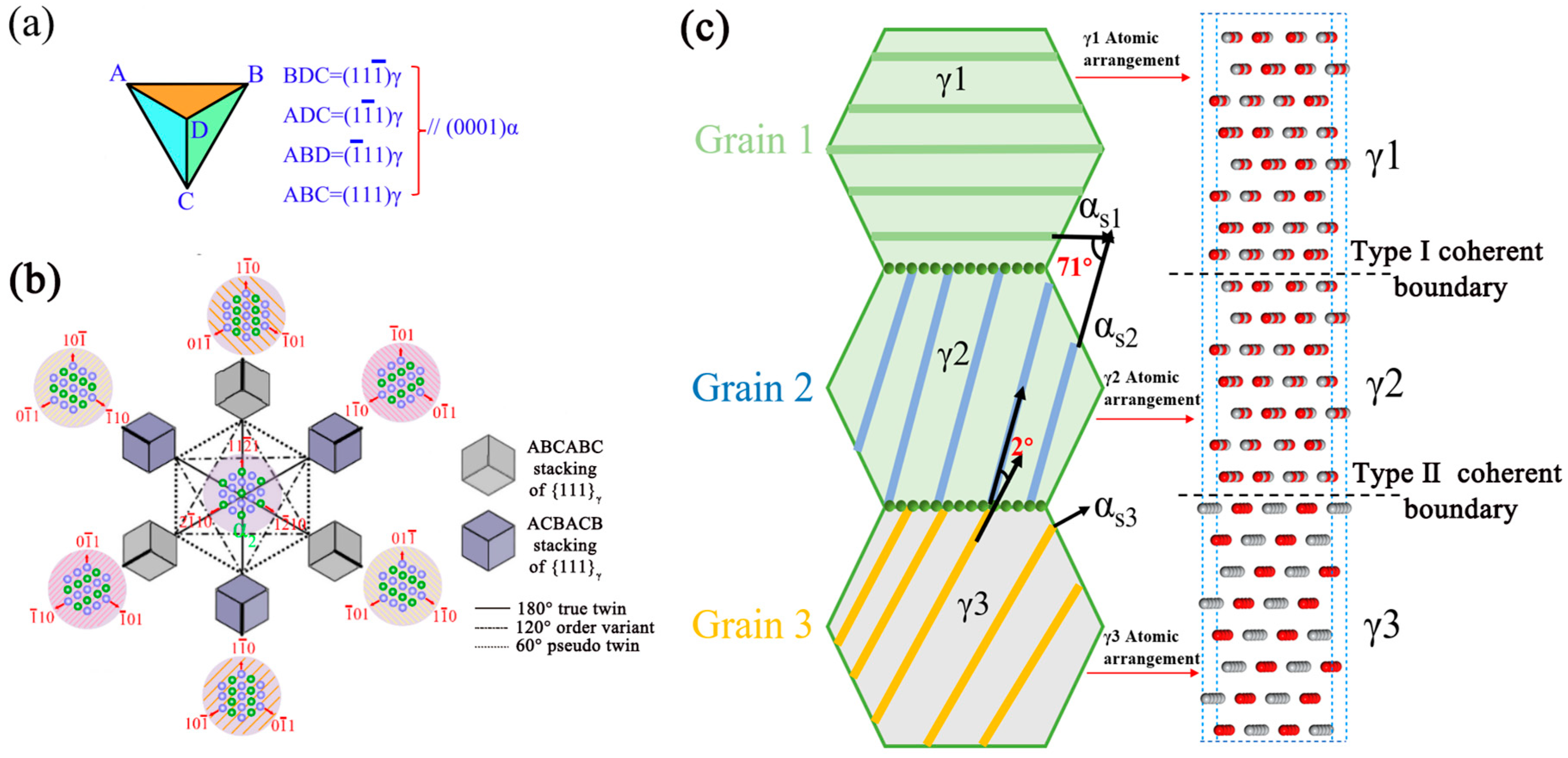
Therefore, it can be found that after cyclic heat treatment, the grain boundaries change from disordered large-angle grain boundaries to fine, coherent small-angle grain boundaries. The formation of refined grain with coherent boundaries is identified as two kinds of variant selection processes: (1) During the cooling process in the single-phase region, metastable γ structure can be promoted by Ta in TiAl-based alloys. Due to the tetragonality in the L10 γ metastable phase, the length in a direction is larger than the b and c directions. The (110] direction is not equivalent to the other two (101] directions; three possible (110] directions can be identified in the {111} habit plane (Figure 5a). Meanwhile, two stacking faults, ABCABC and ACBACB, are observed. Thereafter, there exist six possible orientation variants for the γ metastable phase that originated from one given α grain. Thereafter, the growth of subgrains in metastable γ is the variants selection process along {111}γ habit plane [13], that make the adjacent γ grain have 120° rotational, twin-related (pseudo-twin or true-twin) coherent interface; (2) On the other hand, during short time holding at single α phase region, due to one γ phase having four close packed planes labeled as BCD, ADC, ABD, and ABC followed by the Thopmpson tetrahedral model (Figure 5b), four possible αsvariants are confined to precipitate from the coherent γ metastable phase. Based on this, the 71° misorientation of adjacent αs grain in Figure 4a demonstrates these two αs variants originated from one γ grain, which have been observed to be { 3 - 301 } < 11 2 - 0 > α2 twinning [23]. Thereafter, based on the EBSD and TEM results, two types of coherent grain boundaries can be identified, as illustrated in Figure 5c. For Type I coherent boundary, the crystal structures of γ1 and γ2 grains are identical, while αs1 and αs2 grains display as twins. For the Type II coherent boundary, γ2 and γ3 grains display a 120° rotational interface, while the crystal structures of αs2 and αs3 grains are identical.

3.2. Isothermal Oxidation Behaviors

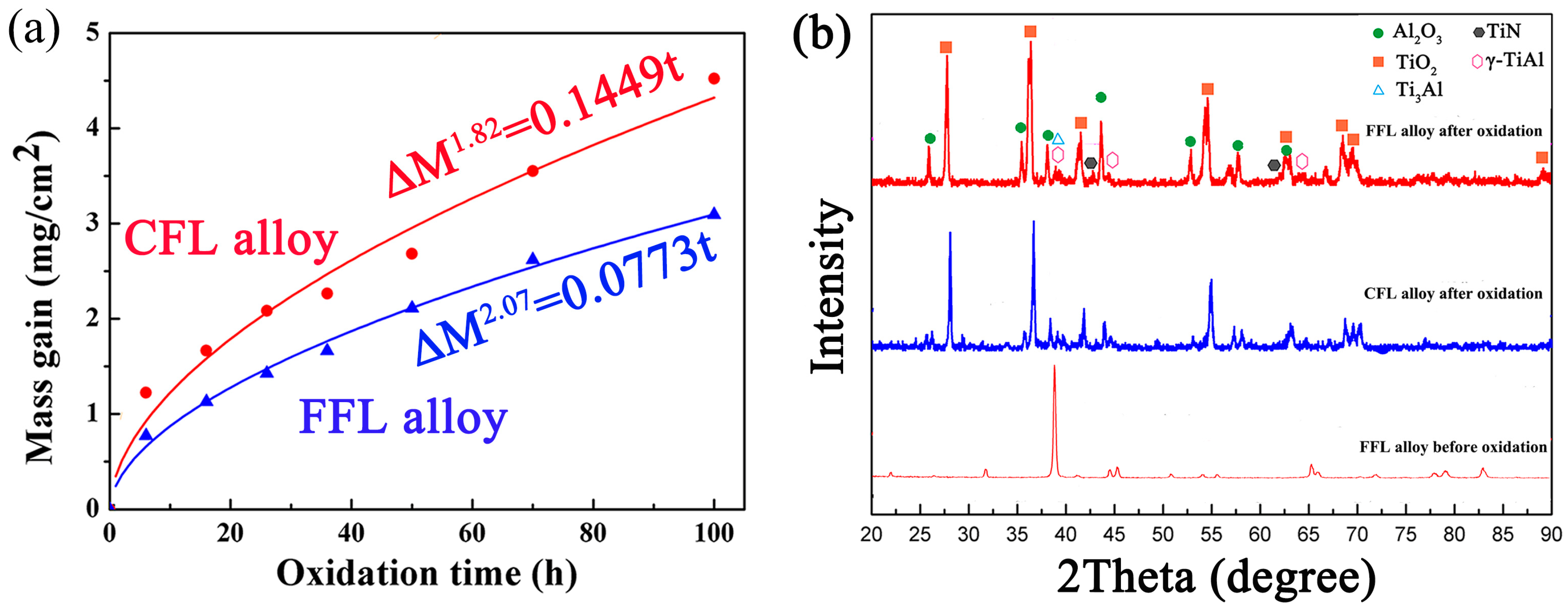
The original microstructures of both coarse FL (CFL) and fine FL (FFL) alloys are shown in Figure 1b,c, respectively. After being isothermally exposed at 1000 °C for 100 h, the mass gain of both CFL and FFL alloys is measured and summarized in Figure 6a. It is obvious that the mass gain increases significantly with the increase in exposure time. The details of the relationship between oxidation mass gain (∆M) and oxidation time (t) can be calculated by the linear fitting equation in Equation (1):
( M ) n = k t
where k is the oxidation reaction rate constant (mgn/cm2n⋅h) and n is the oxidation reaction exponent [10,24]. After fitting calculation, the values of n for CFL alloy and FFL alloy are 1.82 and 2.07, respectively. Compared with the CFL alloy, the FFL alloy has a higher n value, which indicates better oxidation resistance at 1000 °C. In general, the mass gain of the FFL alloy is 3.09 mg/cm2, which is 31.6% lower than that of the CFL alloy (4.52 mg/cm2). Under this condition, the oxidation rate constant of FFL alloy (k = 0.0773) is 46.7% lower than that of CFL alloy (k = 0.1449).
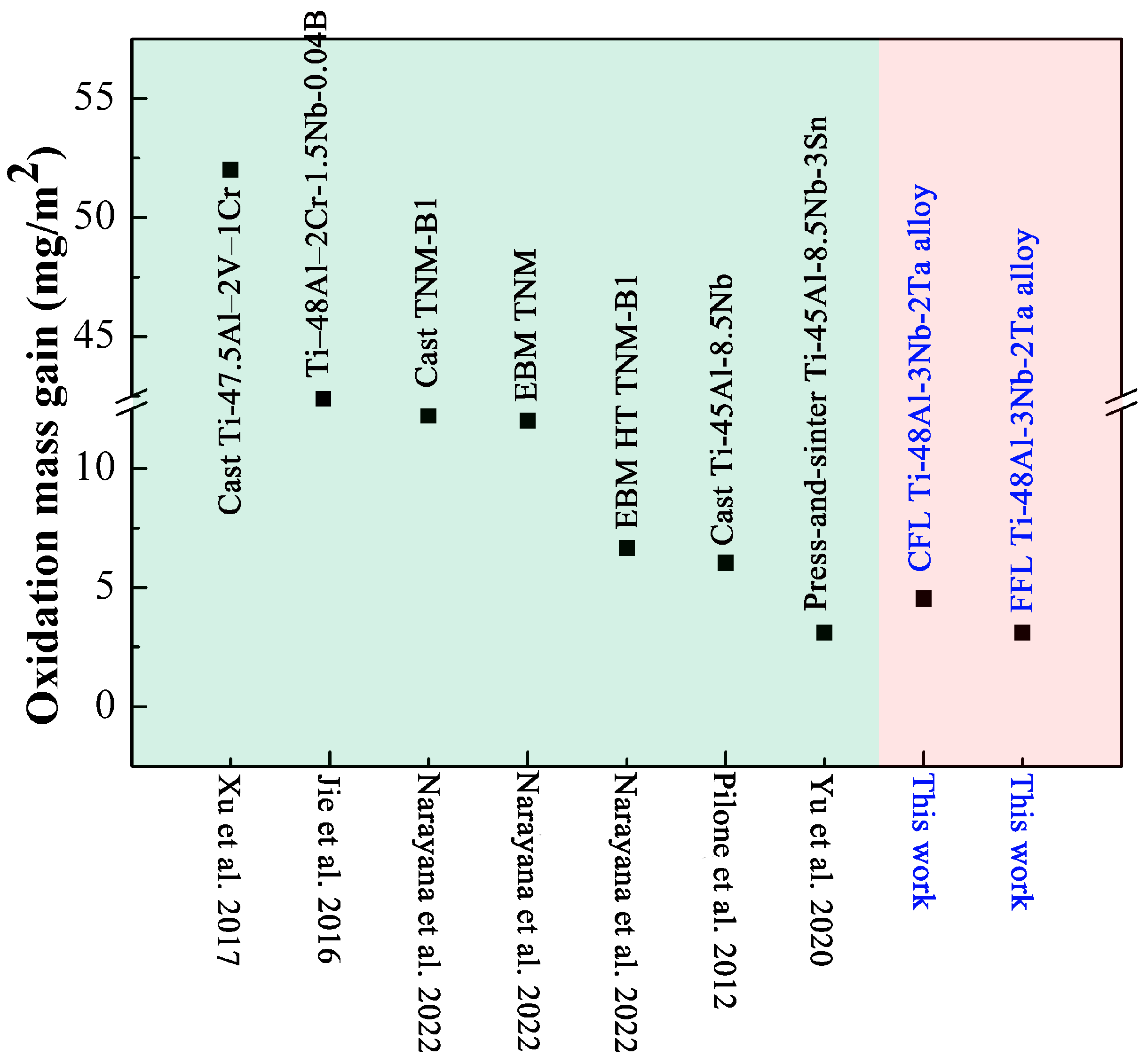
Figure 6b illustrates the XRD diffraction patterns of FFL alloys before the oxidation process and CFL and FFL alloys after the oxidation process at 1000 °C for 100 h. It is clearly shown that the surface of both alloys is mainly composed of TiO2 and Al2O3 particles. Furthermore, the peak intensity of TiO2 increases while that of Al2O3 decreases in the FFL alloy compared with the CFL alloy, indicating that the oxidation surface of the FFL alloy is mainly composed of TiO2. The weak diffraction peaks of TiN can also be identified by the XRD patterns. Nitrogen at high temperatures has a strong binding force with the Ti element; thus, TiN is identified after oxidation. Moreover, compared with other TiAl-based alloys conducted in previous studies [8,11,25,26,27], the FFL alloys possess the best oxidation resistance at 1000 °C for 100 h, which is even higher than the high Nb-containing TiAl-based alloys, attributed to the refinement of grain size (Figure 7).

3.3. Microstructure of Surface and Cross-Section after Oxidation

The surface morphology of CFL and FFL alloys after 100 h of oxidation is depicted in Figure 8. For CFL alloy, oxidation surface morphologies (Figure 8a) illustrate coarse and less dense non-uniform oxidation particles. The corresponding composition measured by EDS (Figure 8c,d, spot 1) shows the large particles containing 42% O and 23% Al should be Al2O3 particles. The small particles that gather together contain 29% O and 51% Ti (Figure 8c,d, spot 2) and should be TiO2. This indicates that the surface is composed of large TiO2 + Al2O3 particles. In contrast, the oxidation particles of the FFL alloy are more uniform and smaller (Figure 8b) compared with those of the CFL alloy. The EDS analysis reveals uniformly distributed small TiO2 oxide particles on the surface, as shown in Figure 8e,f, spot 1, with a composition of 32% O and 5% Ti. The small Al2O3 particles containing 38% O and 29% Al (spot 2) distribute under the TiO2 layer.
The SEM images of oxide layers and their corresponding compositional maps in the cross-section are shown in Figure 9. For the CFL alloy (Figure 9a), layer I is identified as an Al2O3 + TiO2 mixed layer, and the size of Al2O3 and TiO2 particles is growing to be large for the high-temperature oxidation process. Meanwhile, the N element is enriched near the TiO2 particles, which is confirmed to be TiN by XRD (Figure 6b). The mixed layer is then replaced by a continuous and protective Al2O3 layer (II). Layer III is a continuous layer of TiO2, while layer IV represents another mixed Al2O3 + TiO2 layer with solid solutions of Nb and Ta in TiO2. Finally, the innermost layer V is identified as a mixed layer of TiN, Al2O3, and a discontinuous (Nb,Ta)-rich phase.
For the FFL alloy (Figure 9b), however, layer I is identified as a single TiO2 layer, which is also confirmed by XRD in Figure 6b and SEM in Figure 8b. Layer II consists of a continuous Al2O3 protective layer, followed by a continuous TiO2 layer (III). Layer IV is a TiO2 and Al2O3 mixed layer. It should be noted that layer V is a single and continuous TiO2 layer again with solid solutions Nb and Ta. And layer VI is a continuous TiN layer with many fine-grained Al2O3 oxide pegs. The innermost layer VII is composed of a white and continuous (Nb,Ta)-rich layer about 1 μm.
Besides, a distinct feature is a Nb and Ta-depletion zone in the TiN layer, both in the CFL and FFL alloys, indicating the solubility of Nb and Ta in the TiN phase is limited. Furthermore, the thickness of the whole oxide film of CFL alloy and FFL alloy (Figure 9a,b) decreases from 35 µm to 30 µm.
In order to further illustrate the typical microstructure of the innermost oxide layer of both alloys, the transition zone morphology is illustrated in Figure 10, and the EDS composition content of points 1 to 7 is shown in Table 1. It can be clearly seen that for the CFL alloy in Figure 10a, the inner layer (IV) TiO2 particles (point 1) with solid solution Nb and Ta are porous with white contrast and mixed with massive Al2O3 (point 2) with black contrast. For the innermost layer, TiN (point 3) is identified among the large Al2O3 peg and the discontinuous (Nb,Ta)-rich phase (Al (Nb,Ta)2 (point 4)). It is worth noticing that this kind of discontinuous oxide film, especially the boundaries between the Al2O3 peg and the Al (Nb,Ta)2 particle, cannot inhibit the oxygen from diffusing into the substrate; therefore, internal oxidation occurs during the whole oxidation process in the CFL alloy. In addition, for the FFL alloy (Figure 10b), a continuous TiO2 layer (layer V) with solid solutions of Nb and Ta is observed (point 5). Especially, the content of Nb and Ta in TiO2 of the point 1 and point 5 are 3.07Nb, 1.89Ta (CFL alloy), 8.47Nb, and 3.81Ta (FFL alloy), respectively, indicating more Nb and Ta can enrich the TiO2 of the FFL alloy. A continuous TiN (VI, point 6) layer is identified, followed by the TiO2 layer accompanied by fine-grained Al2O3 oxide pegs. The innermost layer VII is confirmed as continuous Al(Nb,Ta)2 (point 7). Thereafter, continuous (Ti, (Nb, Ta))O2, TiN, and Al(Nb,Ta)2 multi-layers can provide good protection during oxidation.

4. Discussion

Figure 11 schematically describes the oxidation mechanisms of CFL and FFL alloys. The oxidation behavior is mainly controlled by element diffusion, which involves the outward diffusion of Ti, Al, Nb, and Ta ions and the inward diffusion of O and N ions, as indicated by the analysis of the oxidation mass gain curve (Figure 6a). Diffusion and oxidation occur at a given temperature T of 1000 °C. Oxygen diffusion is similar to the classical solid-state diffusion theory described by Equation (2):
D = D 0 e x p ( Q k T )
where D0 is the pre-exponential, Q is the activation energy, and k is the universal gas constant. The diffusion coefficients D in the grain area and the boundary area are different due to the different values of Q. In the grain area with a coherent interface, the barrier over which atoms jump is larger than that in the boundary area. It has been certified that the D value in the boundary area is at least two orders higher than the grain area [18]. In other words, the diffusion at large-angle grain boundaries is much faster than the grain phase or the coherent interfaces.
Based on this, although CFL alloys have a small amount of grain boundaries, they can provide the path for the diffusion of Ti, Nb, Ta, and Al ions to the outside and diffusion of O and N ions to the inside, resulting in large and less dense TiO2 + Al2O3 mixed oxide particles at the outmost layer. With the consumption of Ti and Al, the Al2O3 layer, Al2O3 + TiO2 mixed layer, TiO2 layer, Al2O3 + TiO2 mixed layer, and discontinuous TiO2, TiN, and Al (Nb,Ta)2 phases are formed in sequence. In this situation, the oxide films, especially the discontinuous innermost Al2O3 peg and Al (Nb,Ta)2 particles, are not protective enough to inhibit the inward diffusion of O and N ions, which is also certified by other studies [10,28]. The study conducted by Gao et al. [29] also confirms that the discontinuous TiO2, TiN, and Al (Nb,Ta)2 phases next to the substrate are observed after oxidation for 200 h at 900 °C in the TiAl-1.5 Ta alloy with a coarse lamellae microstructure.
For the FFL alloy, due to the formation of different kinds of coherent grain boundaries, the diffusion velocity for O, N, Ti, and Al can be slowed down in contrast with the large-angle grain disorder grain boundaries. TiO2, with more oxygen vacancies, grows faster than Al2O3 [18]. As a result, uniformly distributed small TiO2 oxide particles form on the surface. Furthermore, Ti, Nb, and Ta have similar valence electronic structures and ionic radii for 0.64 Å of Nb5+, 0.72 Å Ta5+, and 0.605 Å of Ti4+ [30]. Ti, Nb, and Ta can mutually dissolve [31], resulting in Nb and Ta occupying the position of Ti to form the (Ti, (Nb, Ta))O2 layer. Therefore, Nb and Ta can be distributed uniformly during the diffusion process instead of segregating at disordered grain boundaries, which can promote the formation of a continuous (Ti, (Nb, Ta))O2 layer near the substrate.
While the concentration of O can be reduced by the continuous (Ti, (Nb, Ta))O2 layer, nitrogen remains trapped in the innermost area. Due to the strong binding force with the Ti element, Equation (3) is activated to form a continuous TiN layer, as shown below:
Ti + [N] = TiN
where [N] represents atoms or ions initiating the dissolution and decomposition of nitrogen at high temperatures. Usually, TiN, which is selected as a wear-resistant coating, is an extremely hard ceramic material. The nano hardness and elastic modulus for TiN film are 20.50 GPa and 281.66 GPa, respectively [31], which can improve the wear, corrosion, and even oxidation properties of alloys because a continuous nitride layer can prevent fast internal oxidation [32].
Besides, the formation of TiN could consume the Ti element, and TiN has a low solubility for Nb and Ta (Figure 10 and Table 1) due to the strong Ti-N bond [33]. The reaction of (Nb,Ta)O2 and Al at the film/substrate interface can be promoted to form the Al(Nb,Ta)2 phase with fine-grained Al2O3 oxide pegs via Equation (4) [8].
11Al + 6(Nb,Ta)O2 = 3Al(Nb,Ta)2 + 4Al2O3
As a result, the innermost oxide films with continuous multi-layered (Ti, (Nb, Ta))O2, TiN, and Al(Nb,Ta)2 layers in FFL alloys are formed, which can greatly reduce the diffusion rate of oxygen and nitrogen. Evidently, the FFL alloys possess the best oxidation resistance at 1000 °C for 100 h, which is even higher than the high Nb-containing TiAl-based alloys, attributed to the refinement of grain size.
The improvement in oxidation resistance of the FFL TiAl alloy is mainly contributed by the following aspects: (1) the coherent boundaries have lower diffusion coefficients than the grain boundaries, which can slow down the diffusion of oxidation towards the substrate; (2) heavy elements such as Nb and Ta are uniformly distributed during the diffusion process instead of being segregated at disordered grain boundaries, which promotes the formation of a continuous (Ti, (Nb, Ta))O2 layer; (3) the formation of a continuous TiN and Al(Nb,Ta)2 layer can be induced by the (Ti, (Nb, Ta))O2 layer, inhibiting O and N atom diffusion.

5. Conclusions

The refinement of TiAl-based alloys (CFL and FFL) prepared by cyclic heat treatment and their corresponding isothermal oxidation behavior were compared in detail. The grain refinement process and related oxidation mechanisms are revealed. The main results are as follows:
(1)
The CFL (~400 μm) TiAl alloy can be refined to 40 μm through metastable γ structures by cyclic heat treatment. After oxidation tests at 1000 °C for 100 h, the lowest mass gain is 3.09 mg/cm2 of the FFL alloy, which is 31.6% lower than the CFL alloy.
(2)
Two kinds of variant selection processes: the coherent metastable γ variants of 120° rotational interface precipitated during the air-cooling process to form a Type II coherent boundary, as well as αs variants originated from one metastable γ variant during holding at the single α phase region process, could promote the formation of Type I coherent boundaries of FFL alloy.
(3)
Coherent grain boundaries can reduce oxidation diffusion toward the substrate. Additionally, heavy elements of Nb and Ta are uniformly distributed during the diffusion process instead of being segregated at disordered grain boundaries. This promotes the formation of a continuous protective barrier consisting of (Ti, (Nb, Ta))O2, TiN, and Al(Nb,Ta)2 layers.

Author Contributions

Conceptualization, K.Z. and L.Z.; Methodology, J.L.; Investigation, K.Z. and L.Z.; Resources, J.L.; Data curation, L.Z.; Writing—original draft, L.Z.; Writing—review and editing, K.Z.; Funding acquisition, K.Z. All authors have read and agreed to the published version of the manuscript.

Funding

This work was financially supported by the Natural Science Basic Research Program of Shaanxi (Program No. 2022JQ-359) and the Scientific Research Program Funded by the Shaanxi Provincial Education Department (Program No. 23JK0598).

Data Availability Statement

The original contributions presented in the study are included in the article, further inquiries can be directed to the corresponding author/s.

Conflicts of Interest

The authors declare no conflicts of interest.

References

  1. Chen, G.; Peng, Y.; Zheng, G.; Qi, Z.; Wang, M.; Yu, H.; Dong, C.; Liu, C.T. Polysynthetic twinned TiAl single crystals for high temperature applications. Nat. Mater. 2016, 14, 876–881. [Google Scholar] [CrossRef] [PubMed]
  2. Kim, J.Y.; Park, E.S.; Lee, T.; Ryu, S.; Kim, S.E.; Kim, S.W. Origin of enhanced room temperature ductility in TiAl alloys: Reducing activation difference of deformation mechanism of γ phase. J. Alloys. Compd. 2022, 899, 163307. [Google Scholar] [CrossRef]
  3. Fang, H.; Wang, S.; Chen, R.; Xu, Q.; Yan, Y.; Su, Y.; Guo, J. The effects of the formation of a multi-scale reinforcing phase on the microstructure evolution and mechanical properties of a Ti2AlC/TiAl alloy. Nanoscale 2021, 13, 12565. [Google Scholar] [CrossRef] [PubMed]
  4. Sun, T.; Guo, Z.; Cao, J.; Liang, Y.; Lin, J. Isothermal oxidation behavior of high-Nb-containing TiAl alloys doped with W, B, Y, and C/Si. Corros. Sci. 2023, 213, 110980. [Google Scholar] [CrossRef]
  5. Pflumm, R.; Donchev, A.; Mayer, S.; Clemens, H.; Schütze, M. High-temperature oxidation behavior of multi-phase Mo-containing γ-TiAl-based alloys. Intermetallics 2014, 53, 45–55. [Google Scholar] [CrossRef]
  6. Mitoraj, M.; Godlewska, E.M. Oxidation of Ti-46Al-8Ta in air at 700 °C and 800 °C under thermal cycling conditions. Intermetallics 2013, 34, 112–121. [Google Scholar] [CrossRef]
  7. Swadźba, R.; Marugib, K.; Pyclik, Ł. STEM investigations of γ-TiAl produced by additive manufacturing after isothermal oxidation. Corros. Sci. 2020, 169, 108617. [Google Scholar] [CrossRef]
  8. Yu, P.; Xin, L.; Muhammad, D.H.; Yang, F.; Liu, C.; Li, Y.; Li, X.; Xu, W.; Qu, X.; Cao, P. Effect of Sn addition on the high-temperature oxidation behavior of high Nb-containing TiAl alloys. Corros. Sci. 2020, 166, 108449. [Google Scholar]
  9. Tian, S.; He, A.; Liu, J.; Zhang, Y.; Yang, Y.; Zhang, Y.; Jiang, H. Oxidation resistance of TiAl alloy improved by hot-pack rolling and cyclic heat treatment. Mater. Charact. 2021, 178, 111196. [Google Scholar]
  10. Liang, Z.; Xiao, S.; Yue, H.; Li, X.; Li, Q.; Zheng, Y.; Xu, L.; Xue, X.; Tian, J.; Chen, Y. Tailoring microstructure and improving oxidation resistance of an additively manufactured high Nb containing TiAl alloy via heat treatment. Corros. Sci. 2023, 220, 111287. [Google Scholar] [CrossRef]
  11. Narayana, P.L.; Kima, J.H.; Yun, D.W.; Kim, S.E.; Reddy, N.S.; Yeom, J.T.; Seo, D.; Hong, J.K. High temperature isothermal oxidation behavior of electron beam melted multi-phase γ-TiAl alloy. Intermetallics 2022, 141, 107424. [Google Scholar] [CrossRef]
  12. Garip, Y. Investigation of isothermal oxidation performance of TiAl alloys sintered by different processing methods. Intermetallics 2020, 127, 106985. [Google Scholar] [CrossRef]
  13. Zhang, K.R.; Hu, R.; Lei, T.C.; Yang, J.R. Refinement of massive γ phase with enhanced properties in a Ta containing γ-TiAl-based alloys. Scripta Mater. 2019, 172, 113–118. [Google Scholar] [CrossRef]
  14. Hu, R.; Wu, Y.; Yang, J.; Gao, Z.; Li, J. Phase transformation pathway and microstructural refinement by feathery transformation of Ru-containing γ-TiAl alloy. J. Mater. Res. Technol. 2022, 18, 5290–5300. [Google Scholar] [CrossRef]
  15. Wei, D.X.; Koizumi, Y.; Nagasako, M.; Chiba, A. Refinement of lamellar structures in Ti-Al alloy. Acta Mater. 2017, 125, 81–97. [Google Scholar] [CrossRef]
  16. Zhang, K.R.; Hu, R.; Li, J.; Yang, J.; Gao, Z. Grain refinement of 1 at.% Ta-containing cast TiAl-based alloy by cyclic air-cooling heat treatment. Mater. Lett. 2020, 274, 127940. [Google Scholar] [CrossRef]
  17. Yim, S.; Bian, H.; Aoyagi, K.; Chiba, A. Effect of multi-stage heat treatment on mechanical properties and microstructure transformation of Ti–48Al–2Cr–2Nb alloy. Mat. Sci. Eng. A 2021, 816, 141321. [Google Scholar] [CrossRef]
  18. Chepak-Gizbrekh, M.V.; Knyazeva, A.G. Oxidation of TiAl alloy by oxygen grain boundary diffusion. Intermetallics 2023, 162, 107993. [Google Scholar] [CrossRef]
  19. Liu, Y.; Hu, R.; Kou, H.; Zhang, T.; Wang, J.; Li, J. A mixture of massive and feathery microstructures of Ti48Al2Cr2Nb alloy by high undercooled solidification. Mater. Charact. 2015, 100, 104–107. [Google Scholar] [CrossRef]
  20. Dey, S.R.; Bouzy, E.; Hazotte, A. Features of feathery γ structure in a near-γ TiAl alloy. Acta Mater. 2008, 56, 2051–2062. [Google Scholar] [CrossRef]
  21. Lapin, J.; Marek, K. Effect of continuous cooling on solid phase transformations in TiAl-based alloy during Jominy end-quench test. J. Alloys Compd. 2018, 735, 338–348. [Google Scholar] [CrossRef]
  22. Saage, H.; Huang, A.J.; Hu, D.; Loretto, M.H.; Wu, X. Microstructures and tensile properties of massively transformed and aged Ti46Al8Nb and Ti46Al8Ta alloys. Intermetallics 2009, 17, 32–38. [Google Scholar] [CrossRef]
  23. Gao, Z.; Hu, R.; Zou, H.; Li, J.; Zhou, M.; Luo, X. Metastable microstructure evolution and grain refinement in a Low-Ta containing γ-TiAl alloy through heat treatment. J. Mater. Res. Technol. 2024, 29, 3642–3655. [Google Scholar] [CrossRef]
  24. Xu, Y.X.; Lu, J.T.; Yang, X.W.; Yan, J.B.; Li, W.Y. Effect and role of alloyed Nb on the air oxidation behaviour of Ni-Cr-Fe alloys at 1000 °C. Corros. Sci. 2017, 127, 10–20. [Google Scholar] [CrossRef]
  25. Jie, L.; Xiangyi, X. Isothermal oxidation behavior of TiAl-Nb-W-B-Y alloys with different lamellar colony sizes. Rare Met. Mater. Eng. 2016, 45, 1695–1699. [Google Scholar] [CrossRef]
  26. Pilone, D.; Felli, F. Isothermal oxidation behaviour of TiAl-Cr-Nb-B alloys produced by induction melting. Intermetallics 2012, 26, 36–39. [Google Scholar] [CrossRef]
  27. Gui, W.; Liang, Y.; Qin, J.; Wang, Y.; Lin, J. Fluorine Effect for Improving Oxidation Resistance of Ti-45Al-8.5Nb Alloy at 1000 °C. Materials 2022, 15, 2767. [Google Scholar] [CrossRef]
  28. Dadéa, M.; Esin, V.A.; Nazéa, L.; Sallot, P. Short- and long-term oxidation behaviour of an advanced Ti2AlNb alloy. Corros. Sci. 2019, 148, 379–387. [Google Scholar] [CrossRef]
  29. Gao, Z.; Hu, R.; Zou, H.; Zhou, M.; Luo, X. Insight into the Ta alloying effects on the oxidation behavior and mechanism of cast TiAl alloy. Mater. Design 2024, 241, 112941. [Google Scholar] [CrossRef]
  30. Zatsepin, D.A.; Boukhvalov, D.W.; Kurmaev, E.Z.; Zhidkov, I.S.; Kim, S.S.; Cui, L.; Gavrilov, N.V.; Cholakh, S.O. XPS and DFT study of Sn incorporation into ZnO and TiO2 host matrices by pulsed ion implantation. Phys. Status Solidi 2015, 252, 1890–1896. [Google Scholar] [CrossRef]
  31. Dai, J.J.; Zhu, J.Y.; Chen, C.Z.; Weng, F. High temperature oxidation behavior and research status of modifications on improving high temperature oxidation resistance of titanium alloys and titanium aluminides: A review. J. Alloys Compd. 2016, 685, 784–798. [Google Scholar] [CrossRef]
  32. Quadakkers, W.J.; Schaaf, P.; Zheng, N.; Gil, A.; Wallura, E. Beneficial and detrimental effects of nitrogen on the oxidation behaviour of TiAl-based intermetallics. Mater. Corros. 1997, 48, 28–34. [Google Scholar]
  33. Wang, S.; Zhang, Y.; Qin, Y.; Lu, J.; Liu, W. Improvement of TiN coating on comprehensive performance of NiTi alloy braided vascular stent. Ceram. Int. 2023, 49, 13405–13413. [Google Scholar] [CrossRef]
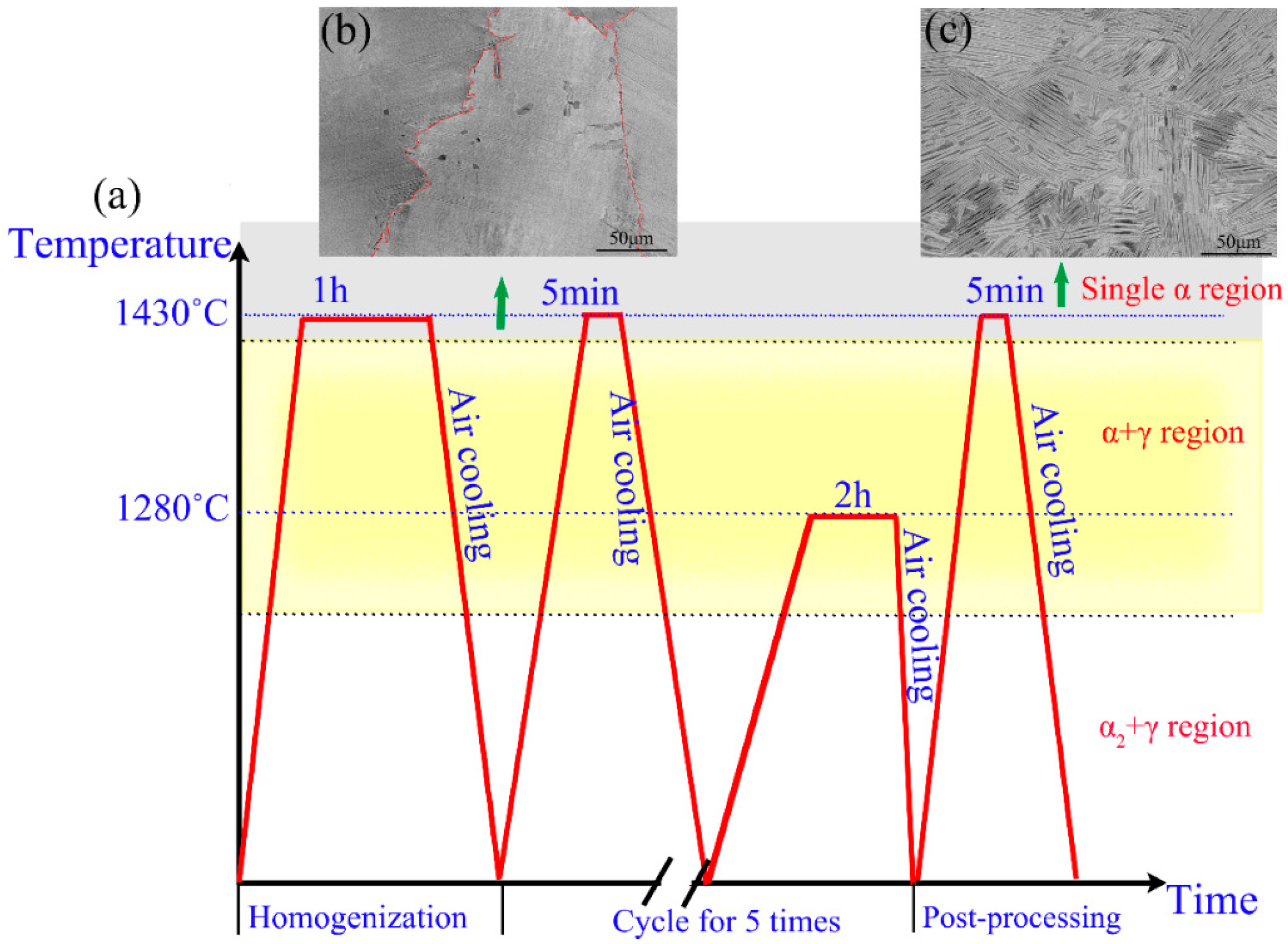
Figure 1. Schematics of cyclic heat-treatment route (a) and corresponding microstructure (b) after homogenization treatment, (c) after five cycles of cyclic heat treatment.
Metals 14 00521 g001
Figure 2. Band contrast, Inverse pole figure (IPF), KAM and boundary maps of the Ti-48Al-3Nb-2Ta alloy with different cycle times; (a,d,g,j) after homogenization; (b,e,h,k) 3 cycles; (c,f,i,l) 5 cycles.
Metals 14 00521 g002
Figure 3. Inverse pole figure (IPF) and pole figures (PFs) maps of Ti-48Al-3Nb-2Ta alloy after cycling five times.
Metals 14 00521 g003
Figure 4. TEM images of coherent grain boundaries: (a) Type I coherent grain boundary and (c) corresponding SADPs in red cycle in (a); (b) Type II coherent boundary and (d,e) corresponding SADPs in red cycle in (b); (f,g) HAADF images of Type I and Type II coherent boundaries, respectively.
Metals 14 00521 g004
Figure 5. Schematic images: (a) Thopmpson tetrahedral model of the γ phase; (b) the six orientation variants of γ phase with the basal plane of a α grain; (c) the structure of coherent boundaries.
Metals 14 00521 g005
Figure 6. (a) Oxidation mass gain curve of CFL and FFL alloys at 1000 °C for 100 h; (b) corresponding XRD diffraction patterns.
Metals 14 00521 g006
Figure 7. Oxidation resistance of CFL and FFL alloys at 1000 °C for 100 h compared with the data in literature (note: EBM: electron beam melting; HT: Heat treatment) [8,11,24,25,26].
Metals 14 00521 g007
Figure 8. The surface morphology after oxidation of CFL alloy (a) and FFL alloy (b); (c,d) the enlarged view and corresponding composition marked in (a); (e,f) the enlarged view and corresponding composition marked in (b).
Metals 14 00521 g008
Figure 9. The cross-sectional morphologies of CFL and FFL alloys after oxidation at 1000 °C for 100 h: (a) SEM images of CFL alloy; (a1a6) EDS composition mapping of rectangles marked in (a); (b) SEM images of FFL alloy; (b1b6) EDS composition mapping of rectangles marked in (b).
Metals 14 00521 g009
Figure 10. The transition zone morphology of (a) CFL alloy and (b) FFL alloy.
Metals 14 00521 g010
Figure 11. Schematic diagram of oxidation process of CFL alloy (a) and FFL alloy (b).
Metals 14 00521 g011
Table 1. The EDS composition results of sites from 1 to 7 are marked in Figure 10.
SiteElement Composition (wt.%)Corresponding Oxide
TiAlNbTaON
147.6610.523.071.8933.273.59TiO2
219.2141.172.271.2136.140Al2O3
33814.61.41.234.610.2TiN
421.3542.2218.137.064.976.27Al(Nb, Ta)2
550.3413.238.473.8120.923.23TiO2
650.0727.321.671.38.5511.09TiN
724.7644.615.286.355.633.38Al(Nb, Ta)2
Disclaimer/Publisher’s Note: The statements, opinions and data contained in all publications are solely those of the individual author(s) and contributor(s) and not of MDPI and/or the editor(s). MDPI and/or the editor(s) disclaim responsibility for any injury to people or property resulting from any ideas, methods, instructions or products referred to in the content.