Abstract
In this work, two types of nanoporous alumina membranes were prepared and tested. Structural features of the samples obtained by using different acids were investigated by scanning electron microscopy (SEM). And further SEM-images were analyzed by different types of fractal dimension estimation methods. The transmission and scattering of accelerated He+ ions were studied in experiments on the ion irradiation of dielectric channels based on porous alumina. An ion accelerator was used as a source of the He+ beam with an energy of 1.7 MeV. Ion scattering was studied by Rutherford backscattering spectrometry. Helium transition through nanoporous alumina at various angles between the normal to the sample and the beam direction were observed. It is shown that the porous structure of anodic aluminum oxide is excellent as a dielectric matrix of nanocapillaries. Owing to the small angle scattering, it allows for the transportation of the accelerated charged particles through the dielectric capillaries, and, as a result, the localization of high energy ion irradiation effects. Additionally, according to the transmission of UV–V is spectra, the energy gaps of samples obtained were calculated.
1. Introduction
Synthesis, the study of nanomaterials and the consideration of new areas of their application are increasingly attracting the attention of scientists from different countries) [1,2,3]. For many applications, materials with capillaries or porous membranes that can be used as focusing devices are interesting because of their transmitting properties. For such purposes, a crucial objective is the dependence of the ion transmission coefficient on the incidence angle of the beam. Authors [4,5,6] have shown that a dielectric channel can form mechanically or by chemical etching. In addition, the publications considered present structures based on porous alumina [7,8,9] and silicon [10] and others [11,12] as promising materials in the field of sensing and the separation of chemicals and compounds, where the properties of the devices being created depend significantly on pore parameters.
In [13,14], the transition of charged Ne7+ ion beams with an energy of 3 keV through dielectric nanocapillaries in a PET film with a thickness of 10 μm was considered. It was found that the output current could be observed even at large angles of inclination of the sample relative to the beam axis, and many ions maintained their charge state. The experiment was repeated using different types of ions in a wide range of energies and different nanocapillary structures. It was also shown that the charge state of the incident ions affects the angular distribution of the ions passed through capillaries. In the case of the beam co-direction and the capillary axis, the shape of the angular distributions for different charge states was identical.
The focusing coefficient is defined as the ratio of the densities of the input and output currents. It depends on the type and energy of the ions and the shape of the capillary. This coefficient varies in a wide range, from 10 for Ar8+ with an energy of 8 keV to 1000 for He+ with an energy of 2 MeV. Studies [15,16,17,18,19] showed that dielectric micro- and nanocapillary structures have great potential for solving a large number of problems, such as bringing an ion beam to air for the microelement analysis of particle-induced X-ray emission (PIXE) and Rutherford backscattering spectrometry (RBS) methods, local microelement analysis, micro- and nanolithography and irradiation of biological objects.
Regarding alumina oxide with a porous structure, some work associated with beam transition and the change of its parameters at the output was conducted. Much attention was paid to the influence of the porous structure parameters on the outgoing beam properties. Nanoporous alumina matrices, also known as porous anodic alumina (PAA), are widely studied for their unique optical properties by Feng S. and Ji W. [20], Domagalski J.T. et al. [21], Ruiz-Clavijo A. et al. [22], Davoodi E. et al. [23], Alvarez-Carrizal R.P. et al. [24], Pandey V.K. et al. [25]. The structural parameters of these matrices can significantly influence their optical characteristics. Controlling these structural parameters in nanoporous alumina matrices allows researchers to improve the optical properties of such materials for various applications in different type of devices, including photonic devices, sensors, optical filters, and photovoltaics, and others. Specific experimental techniques and fabrication processes can influence the optical properties of nanoporous alumina matrices, and further research in this field continues to find new optical phenomena and applications.
Authors [26,27,28] have demonstrated that, while passing through a dielectric channel, positive ions can interact with the channel material and undergo various reactions and processes. Positive ions directed along the dielectric channel can penetrate through the material, passing through its structure. Passing can occur through open pores and channels or through the matrix of the material itself. During this process, ions can collide with the atoms and molecules of the channel material, leading to scattering. Scattering and collisions can alter the trajectories and energies of the ions. This charge exchange interaction can influence the trajectory and energy of the ions. In work [29], the stopping cross-sections for protons and deuterons in aluminum oxide foils were studied at the energy region of 0.9–2.5 MeV. Manzoor S. et al. [30] showed that pores could affect energy loss during the transition of particles through the sample but, at the same time, a guiding effect could appear in the required pore configuration. In [31], the transition of a proton beam with energy from 150 to 320 keV through tapered glass capillaries was considered. As it was presented, when the beam passes through capillaries, the angular width of the initial beam remains almost unchanged. For this case, the transmittance of the target was 10−3. In [32], by means of RBS, it was shown that the maximum transmission of two MeV He+ ions through thick membranes varied from 30% to 65%, which is comparable to the relative surface area covered by pores. The effective atomic surface density of the investigated material was about 4–5 times lower than that for bulk Al2O3. To evaluate the influence of the charge state and the effects of the charge exchange of the incident ion on guiding, in several works, ions were used in the multiply charged state. By means of the Ne6+ irradiation of the alumina, the capillary angular distribution of ions was determined by Juhász Z. et al. [33]. A clear guiding effect was found for 3 and 6 keV ion energies. An important detail was the observation of photons originating from the tilted capillaries. Additionally, authors [34,35] have considered that the low divergence of the beam at the exit from the membrane makes nanoporous alumina a promising material for use as masks for nanolithography.
Thus, the purpose of this research covers several aspects of different scientific fields. Firstly, the aim is to perform a study of the optical properties of porous alumina membranes obtained in various electrolytes over a wide range of wavelengths, which has not been carried out by other scientific groups. Secondly, the passage of accelerated ion beams through nanoporous dielectric capillary matrices is investigated. Thirdly, the fractal dimension of such structures based on porous aluminum oxide is analyzed. And fourthly, by combining all the results, a new theory that explains the electrical properties of nanoporous aluminum oxide membranes is proposed.
2. Materials and Methods
2.1. Production of Porous Alumina Membranes
Matrices of dielectric channels based on porous anodic alumina (PAA) were formed by electrochemical anodizing. The purity of the original substrate determines the ordered hexagonal arrangement of the pores relative to each other. If you use technical foil, then rolling lines will be clearly visible, known as the so-called faceting of the surface. This article discusses porous alumina obtained on 99.999% pure aluminum foil with a thickness of 150 μm. Before anodizing, aluminum foil was subjected to preliminary heat treatment at T = 650 °C for t = 6 h. Next, the surface was washed successively in the following solutions: acetone, alcohol, and distilled water. Concentrated HCl acid (38%) was used to remove the barrier layer.
Studies [36,37] (Min et al., 2020, Romero et al., 2022) have shown that the geometric dimensions of pores depend on technological conditions of membrane formation in a wide range. Pore diameters can vary from nanometers to micrometers. It was investigated how variable technological parameters (electrolyte composition, voltage, etc.) can influence structures. In our study, the used conditional parameters are presented in Table 1.

Table 1.
Technological parameters of electrochemical anodizing of aluminum foil.
For the formation of highly ordered porous alumina with a pore diameter of ≈30 nm, additional stages of the chemical pre-structuring of aluminum foil are required. At the first stage of anodizing, pores are generated in energetically advantageous places, then the upper sacrificial layer is etched away, and nuclei remain on the surface for subsequent pore formation. The introduction of such stages makes it possible to obtain a porous structure as a close-packed ordered structure. As was shown in [38], viscosity plays significant role in a structural formation. The viscosity of the solution slows ionic conductivity to the desired limits to reduce the effect of diffusion polarization near the surface of the processed sample. So, glycerol was used to raise the viscosity of solvents in the etching process.
2.2. Helium İon Transition through Alumina Membrane
To study [39,40,41] the transition of an ion beam through dielectric channels, a facility based on the AN-2500 accelerator (High Voltage Engineering Europa B.V., Amersfoort, Netherlands), located at the SINP MSU, was used. The accelerator, based on the Van de Graaff system, is capable of accelerating particles (protons and He+ ions) to an energy of 2.5 MeV. For the convenience of operations inside the accelerator’s vacuum chamber, all the membranes were fixed using a fluoroplastic disk frame (Figure 1). This made it possible to avoid specimen deformation during testing.
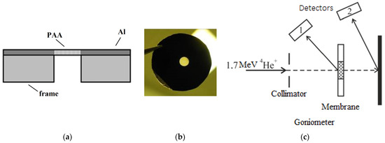
Figure 1.
Schematic image (a) and photograph (b) of the frame for the PAA membrane. Schematic illustration of the experimental setup (c).
A special experimental chamber was created, including collimating diaphragms, a beam monitoring system, a back-scattered ion detection system, and a goniometric system. A collimated beam of 1.2 MeV He+ ions entered the membrane; one part of the beam passed through the capillaries and the current was recorded using a Faraday cup, while the other part was scattered and recorded using a semiconductor detector. In all experiments, the detected scattering angle was 120°. The diameter of the beam on the membrane was about 1 mm. The residual pressure in the chamber did not exceed 5 × 10⁻⁴ Pa. The current density on the target was kept constant at 4 nA.
3. Results and Discussion
3.1. Structural Characterization
3.1.1. SEM Measurements
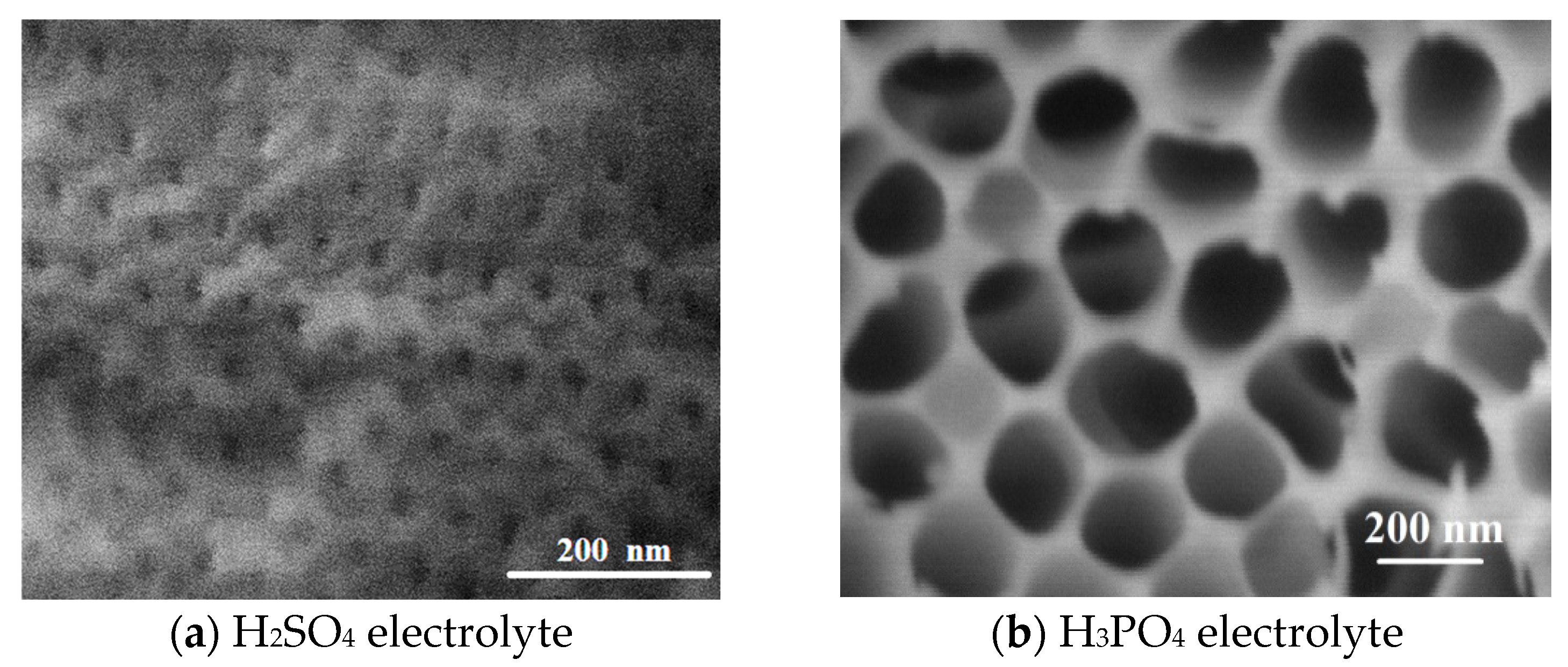
The structure of the obtained membranes was examined using a scanning electron microscope (SEM). The surface structure of the membranes obtained in various electrolytes are shown in Figure 2.

Figure 2.
SEM images of the surface of membranes PAA obtained in different electrolytes.
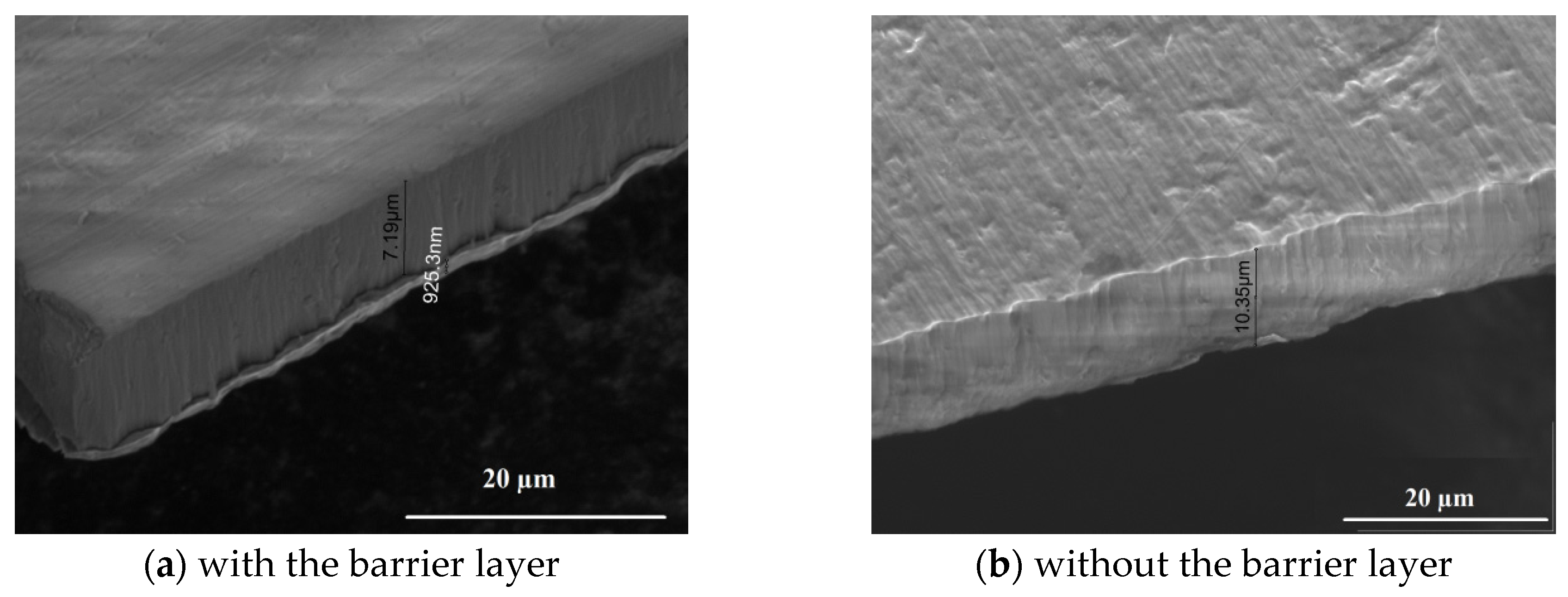
Two series of obtained membranes have pores with significantly different diameter sizes (Figure 2). When using the electrolyte based on H2SO4, membranes with a thickness of about 10 μm are formed, with an average pore diameter of 32 ± 10 nm, a barrier layer thickness of ≈200 nm, and a pore concentration of 350 pieces/μm2. On the other hand, the geometrical parameters of the membranes obtained in the H3PO4-based electrolyte are as follows: an average pore diameter of 207 ± 30 nm, a porous layer thickness of 10 μm, a barrier layer thickness of ≈200 nm, and a pore concentration of 50 pieces/μm2. In all the resulting membranes, there is a barrier layer—the bottom of the pore—that is a layer of dense alumina separating the porous layer from the substrate (Figure 3).
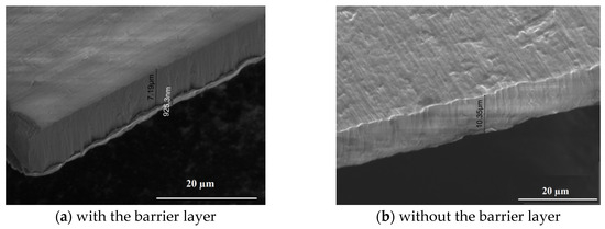
Figure 3.
SEM images of the cross-section of PAA_S membranes before and after the removal of the barrier layer.
The presence of a barrier layer greatly affects the transmittance in experiments on the interaction of membranes with ion beams. In this case, the transmittance is the ratio of the intensity of the transmitted beam of helium ions to the incident beam. The difference in transmittance with and without a barrier layer can differ tenfold. Taking this important point into account, the removal of the barrier layer was carried out by chemical etching of the back side of the membrane in concentrated hydrochloric acid (HCl) for 10 min.
3.1.2. Fractal Dimension Evaluation
Surface topography is usually described in terms of surface roughness. Surface roughness is solely a function of height, that is, information about lateral topography is lost. Studies [42] have shown that fractal dimension parameters allow for a more accurate representation of how sample structural features depend on different factors, such as fabrication conditions, treatment procedures, material compositions and so on.
Here, fractal dimension was estimated from SEM images using cube counting, triangulation and power spectra density methods. Calculation methods are described in detail in [42,43,44]. The algorithm for determining the surface fractal dimension of samples using the cube counting method is as follows: a cubic lattice with lattice constant l is superimposed on a surface stretched along z; starting with X/2 (where X is half the side of the surface), the result is a lattice of 2 × 2 × 2 = 8 cubes; then, N(l) is the number of cubes that contain at least one pixel of the image; the lattice constant l is then successively halved at each step, and the process is repeated until l becomes equal to the distance between two adjacent pixels; the slope of a plot of log(N(l)) versus log(1/l) directly provides the fractal dimension Df.
The triangulation method is quite similar to the cube counting algorithm. It works as follows. A grid with a cell size of one unit of measurement l is placed on the surface. This defines the positions of the vertices of a set of triangles. When, for example, l = X/4, the surface is covered with 32 triangles of different areas, inclined at different angles with respect to the xy plane. The areas of all triangles are calculated and summed to obtain the approximate surface area S(l) corresponding to l. The grid size is then successively halved at each step, as before; the process continues until then, meaning until l becomes equal to the distance between two neighboring points. The slope of the graph of S(l) versus log(1/l) corresponds to Df − 2.
In the power spectrum method, the signal is identified by the roughness profile. In the power spectrum method, a Fourier transform is applied to each height profile along the lines that make up the image; the power spectrum is calculated, and all these spectra are averaged. As a result, PSD represents how the values of Fourier transformed surface heights are distributed over the wavenumbers of spatial frequencies in reciprocal space, i.e., in this way, the spatial frequencies of the occurrence of geometric features observed in surface topography are identified. The fractal dimension is determined from the slope β of the fitting line as Df = 7/2 − β/2, as for self-similar structures.
Results are shown in Table 2. As can be seen from the presented data, the values of the fractal dimension of the samples differ depending on the fabrication method, but they are in good agreement regardless of the estimation method used.
Table 2.
Fractal dimension of obtained PAA samples.
3.2. Optical Properties
3.2.1. He+ Ion Beam Transmission Measurements
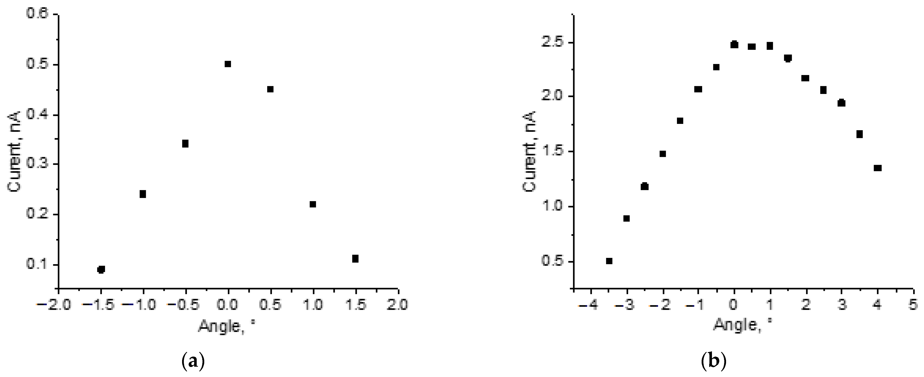
The results of the ion beam transmission through the membranes obtained in an electrolyte based on H3PO4 are demonstrated in Figure 4a. A small part of the ion beam passes through a porous matrix. The transmittance of 0.15 was registered by means of a current measurement device, and a significant current drop was observed when the membrane deviated from the norm by 1.5 degrees.
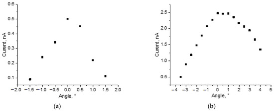
Figure 4.
Dependence of the He+ ion number passing through membranes at the angle of inclination. Membranes obtained in electrolytes based on H3PO4 (a) and H2SO4 (b).
At the same time, the results of accelerated beam transition through membranes prepared in an electrolyte based on H2SO4 (Figure 4b) showed that the intensity of the transmitted beam practically does not change within 2.5 degrees. A twofold reduction in the signal occurs with the rotation of the target by 3 degrees. Measured transmittance was in the range of 0.50–0.625, depending on the sample thickness.
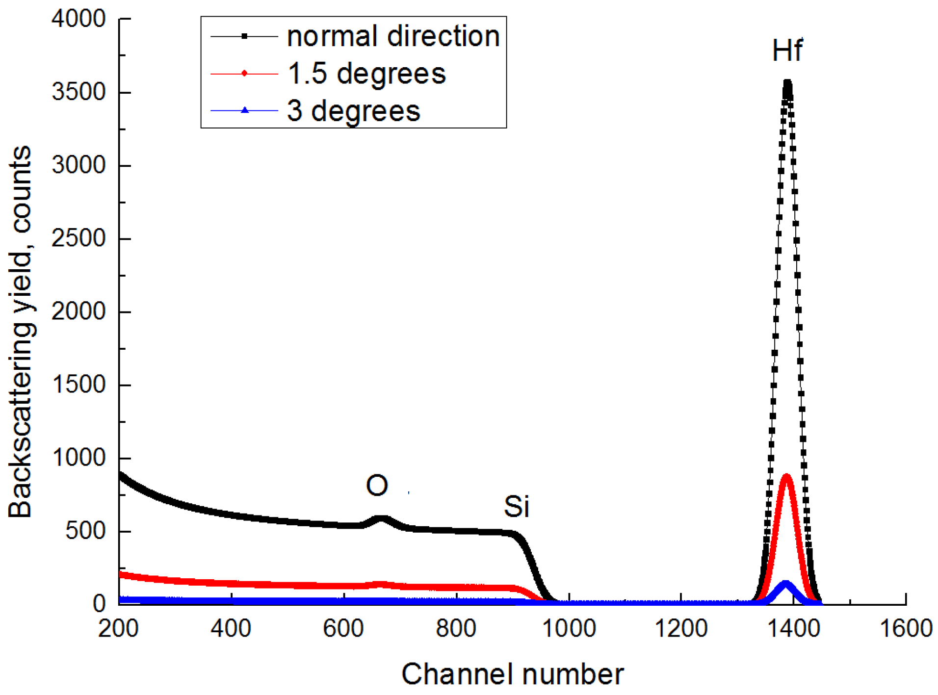
When we registered the number of transmitted ions by a Faraday cup, we did not take into account the secondary electrons emitted from the pore surface. But this could cause an error in the study of the angular distributions and the number of transmitted ions. To exclude secondary electron contribution, a sample consisting of a 20 nm HfO2 film on a monocrystalline silicon substrate was installed behind a porous alumina membrane. Comparing the statistics of the maximum distribution of backscattered particles (Figure 5), the number of high-energy particles passed was ≈0.6 of the initial beam current, as shown in Figure 4. However, with a deviation of 1.5 degrees, the current of the transmitted particles decreased four times, in comparison with the orientation relative to the beam axis (Figure 5). Herewith, up to half of the charged particles passed through the membrane in accordance with the current device. At the same time, with a deviation of 3 degrees in the high-energy part of the spectrum, there were practically no backscattered particles from Hf, and in the case of registration with a current device, 25% of the beam passed through. This suggests that with a small angular scattering on the membrane wall, a sufficiently large number of electrons are generated, which must be considered for the further use of such membranes.
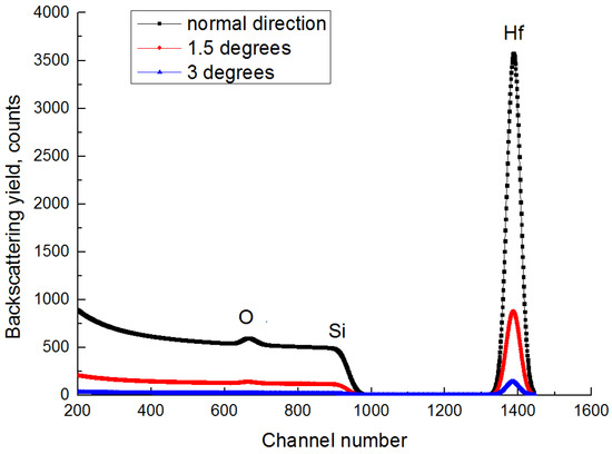
Figure 5.
The energy spectrum of backscattered He+ ions with an energy of 1200 keV. The black curve is the spectrum along the normal direction; the red curve is the spectrum when the deviation is 1.5 degrees from the normal; the blue curve is the spectrum when the deviation is 3 degrees.
The beam energy resolution was estimated using SIMNRA simulation of the slope of the signal obtained by scattering helium ions from the layer of hafnium dioxide. Kots I.N. et al. [45] showed that the resolution of the used spectrometry path is 15 keV. The energy resolution of the RBS technique with the use of a porous alumina membrane worsened and amounted to about 40 keV.
When studying using the energy-dispersive X-ray spectroscopy (EDS) and RBS methods, there were no significant differences in the composition and stoichiometry of the membranes obtained in the electrolytes based on H2SO4 and H3PO4.
3.2.2. Ultraviolet–Visible Spectroscopy (UV–Vis)
The authors [20,46,47,48] of the work carried out studies of the optical properties of PAA membranes (Figure 6) in the visible wavelength range in order to analyze the width of the energy gap.
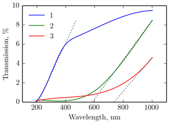
Figure 6.
Transmission spectra of porous alumina membranes obtained in the electrolytes based on the following: 1—H2SO4 + 15% glycerol, 2—H3PO4, and 3—H3PO4 + 15% glycerol.
According to the transmission spectra, it is possible to calculate the energy gaps for PAA membranes with different pore diameters using the following formula (Equation (1)):
where h—Planck’s constant, c—light speed, λ—critical wavelength, at the increase of which light transmission begins. The results of the calculations are presented in Table 3.
Table 3.
Energy gap of Al2O3 membranes with different pore diameters.
The decrease in the band gap in the work is explained by the presence of oxygen vacancies near the valence band (alumina is characterized by an oxygen deficiency). Oxygen vacancies form localization centers for both electrons and holes, and, consequently, cause the splitting of energy levels. When comparing two electrolytes, during dissociation, phosphoric acid releases three hydrogen ions, while sulfuric acid dissociates into SO42− and 2H+. Free hydrogen ions tend to form a bond with oxygen to form water. Consequently, in the first case, more oxygen ions are required and, as a result, more oxygen vacancies are formed in the structure, which leads to the formation of additional levels in the forbidden zone. All this leads to the fact that the formed porous layer in the electrolyte based on H2SO4 has fewer localized levels and, consequently, a larger energy gap (≈6 eV) than when based on H3PO4 (≈2 eV).
Thus, the valence band of the porous layer based on H2SO4 is completely filled with electrons and separated from the free zone following it by a wide energy gap. This structure corresponds to dielectrics that are characterized by a full valence band filled with electrons and a completely free conduction band. If there is no thermal excitation of electrons to conduction band levels, then such materials behave like insulators. With our experimental parameters (the beam current in all experiments did not exceed 15 nA), this condition was always fulfilled. In this case, according to experimental data, a much larger number of ions passes through the membrane based on H2SO4. Thus, the mechanism of ion transition through the membrane is associated not only with small angular scattering, but also, probably, with the effect of charging the pore walls.
4. Conclusions
We have studied porous anodic aluminium oxide membranes with a system of ordered nanoscale (pore diameter of 30 nm and more) capillaries with an aspect ratio of up to five hundred. It was shown that the transmittance of high-energy ion beams for membranes based on H2SO4 is significantly greater than for those based on H3PO4. This could be explained by structural differences. Membranes fabricated using H2SO4 have a higher pore concentration, as well as a higher fractal dimension.
Based on a study of the transmission spectra, the choice of the membrane type for studying the transmission of accelerated beams through the membranes was made in favor of membranes formed in the electrolyte based on H2SO4. Nanoporous alumina-based membranes were used successfully to provide the transporting of high-energy helium ions. For the membrane with a pore diameter of ~32 nm, the transmittances were in the range of 0.50–0.625.
Author Contributions
Methodology, A.A.P., A.P.E. and O.Y.K.; Software, E.N.M., A.A.S. and V.A.M.; Validation, E.N.M., A.A.S., Y.V.B. and A.A.Z.; Formal analysis, E.N.M., A.A.S., A.A.Z. and O.Y.K.; Investigation, E.N.M.; Resources, A.A.P., Y.V.B., V.A.M. and O.Y.K.; Data curation, Y.V.B.; Writing—original draft, A.P.E.; Funding acquisition, A.A.Z. All authors have read and agreed to the published version of the manuscript.
Funding
The study was supported by the Russian Science Foundation Grant No. 23-42-10029, https://rscf.ru/en/project/23-42-10029/. The research is partially funded by the Ministry of Science and Higher Education of the Russian Federation as part of the World-class Research Center program: Advanced Digital Technologies (contract No. 075-15-2022-312 dated 20 April 2022).
Data Availability Statement
The original contributions presented in the study are included in the article material, further inquiries can be directed to the corresponding authors.
Conflicts of Interest
The authors declare no conflict of interest.
References
- Ahmad, N.; Javed, M.; Qamar, M.A.; Kiran, U.; Shahid, S.; Akbar, M.B.; Sher, M.; Amjad, A. Synthesis, characterization and potential applications of Ag@ZnO nanocomposites with S@g-C3N4. Adv. Mater. Res. 2022, 11, 225–235. [Google Scholar] [CrossRef]
- Saad, M.; Hadji, L.; Tounsi, A. Effect of porosity on the free vibration analysis of various functionally graded sandwich plates. Adv. Mater. Res. 2021, 10, 293–311. [Google Scholar] [CrossRef]
- Hamad, L.B.; Khalaf, B.S.; Faleh, N.M. Analysis of static and dynamic characteristics of strain gradient shell structures made of porous nano-crystalline materials. Adv. Mater. Res. 2019, 8, 179–196. [Google Scholar] [CrossRef]
- Stolterfoht, N.; Yamazaki, Y. Guiding of charged particles through capillaries in insulating materials. Phys. Rep. 2016, 629, 1–107. [Google Scholar] [CrossRef]
- Borka, D.; Jovanović, V.B.; Lemell, C.; Tőkési, K. Electron transmission through a macroscopic platinum capillary. Nucl. Instrum. Methods Phys. Res. Sect. B Beam Interact. Mater. At. 2017, 406, 413–416. [Google Scholar] [CrossRef]
- Pinilla, S.; Campo, T.; Sanz, J.M.; Márquez, F.; Morant, C. Highly ordered metal-coated alumina membranes: Synthesis and RBS characterization. Surf. Coat. Technol. 2019, 377, 124883. [Google Scholar] [CrossRef]
- Su, T.; He, L.; Mo, R.; Zhou, C.; Wang, Z.; Wang, Y.; Hong, P.; Sun, S.; Li, C. A non-enzymatic uric acid sensor utilizing ion channels in the barrier layer of a porous anodic alumina membrane. Electrochem. Commun. 2018, 96, 113–118. [Google Scholar] [CrossRef]
- Costa, C.M.; Lee, Y.-H.; Kim, J.-H.; Lee, S.-Y.; Lanceros-Méndez, S. Recent advances on separator membranes for lithium-ion battery applications: From porous membranes to solid electrolytes. Energy Storage Mater. 2019, 22, 346–375. [Google Scholar] [CrossRef]
- Liu, G.; Li, K.; Zhang, Y.; Du, J.; Ghafoor, S.; Lu, Y. A facile periodic porous Au nanoparticle array with high-density and built-in hotspots for SERS analysis. Appl. Surf. Sci. 2020, 527, 146807. [Google Scholar] [CrossRef]
- Evseev, A.P.; Kozhemiako, A.V.; Kargina, Y.V.; Balakshin, Y.V.; Zvereva, E.A.; Chernysh, V.S.; Gongalsky, M.B.; Shemukhin, A.A. Radiation-induced paramagnetic defects in porous silicon under He and Ar ion irradiation. Radiat. Phys. Chem. 2020, 176, 109061. [Google Scholar] [CrossRef]
- Bensaid, I.; Bekhadda, A. Thermal stability analysis of temperature dependent inhomogeneous size-dependent nano-scale beams. Adv. Mater. Res. 2018, 7, 1–16. [Google Scholar] [CrossRef]
- Abdel-Zaher, N.A.; Moselhey, M.T.H.; Guirguis, O.W. Ultraviolet-ozone irradiation of HPMC thin films: Structural and thermal properties. Adv. Mater. Res. 2017, 6, 1–12. [Google Scholar] [CrossRef]
- Stolterfoht, N.; Herczku, P.; Juhász, Z.; Kovács, S.T.S.; Rácz, R.; Biri, S.; Sulik, B. Long-term stable transmission of 3-keV Ne7+ ions guided through nanocapillaries in polymers. Nucl. Instrum. Methods Phys. Res. Sect. B Beam Interact. Mater. At. 2016, 387, 96–102. [Google Scholar] [CrossRef]
- Stolterfoht, N.; Bremer, J.-H.; Hoffmann, V.; Hellhammer, R.; Fink, D.; Petrov, A.; Sulik, B. Transmission of 3 keV Ne7+ Ions through Nanocapillaries Etched in Polymer Foils: Evidence for Capillary Guiding. Phys. Rev. Lett. 2002, 88, 133201. [Google Scholar] [CrossRef]
- Du, G.; Guo, J.; Wu, R.; Guo, N.; Liu, W.; Ye, F.; Sheng, L.; Li, Q.; Li, H. The first interdisciplinary experiments at the IMP high energy microbeam. Nucl. Instrum. Methods Phys. Res. Sect. B Beam Interact. Mater. At. 2015, 348, 18–22. [Google Scholar] [CrossRef]
- Fujita, N.; Ishii, K.; Ogawa, H. Development of two-dimensional mapping technique by in-air-PIXE with metal capillary. Nucl. Instrum. Methods Phys. Res. Sect. B Beam Interact. Mater. At. 2011, 269, 1023–1025. [Google Scholar] [CrossRef]
- Folkard, M.; Prise, K.M.; Grime, G.; Kirkby, K.; Vojnovic, B. The use of microbeams to investigate radiation damage in living cells. Appl. Radiat. Isot. 2009, 67, 436–439. [Google Scholar] [CrossRef]
- Grotzer, M.A.; Schültke, E.; Bräuer-Krisch, E.; Laissue, J.A. Microbeam radiation therapy: Clinical perspectives. Phys. Medica. 2015, 31, 564–567. [Google Scholar] [CrossRef]
- Michelet, C.; Moretto, P. 3D mapping of individual cells using a proton microbeam. Nucl. Instrum. Methods Phys. Res. Sect. B Beam Interact. Mater. At. 1999, 150, 173–178. [Google Scholar] [CrossRef]
- Feng, S.; Ji, W. Advanced nanoporous anodic alumina-based optical sensors for biomedical applications. Front. Nanotechnol. 2021, 3, 678275. [Google Scholar] [CrossRef]
- Domagalski, J.T.; Xifre-Perez, E.; Marsal, L.F. Recent Advances in Nanoporous Anodic Alumina: Principles, Engineering, and Applications. Nanomaterials 2021, 11, 430. [Google Scholar] [CrossRef]
- Ruiz-Clavijo, A.; Caballero-Calero, O.; Martín-González, M. Revisiting anodic alumina templates: From fabrication to applications. Nanoscale 2021, 13, 2227–2265. [Google Scholar] [CrossRef]
- Davoodi, E.; Zhianmanesh, M.; Montazerian, H.; Milani, A.S.; Hoorfar, M. Nano-porous anodic alumina: Fundamentals and applications in tissue engineering. J. Mater. Sci. Mater. Med. 2020, 31, 60. [Google Scholar] [CrossRef]
- Alvarez-Carrizal, R.P.; Rodríguez-García, J.A.; Cortés-Hernández, D.A.; Esparza-Vázquez, S.J.; Rocha-Rangel, E. Manufacture of Al2O3/Ti composite by aluminum bonding reaction for their use as a biomaterial. Adv. Mater. Res. 2021, 10, 331–341. [Google Scholar] [CrossRef]
- Pandey, V.K.; Patel, B.P.; Guruprasad, S. Mechanical properties of Al/Al2O3 and Al/B4C composites. Adv. Mater. Res. 2016, 5, 263–277. [Google Scholar] [CrossRef]
- Vokhmyanina, K.A.; Zhukova, P.N.; Irribarra, E.F.; Kubankin, A.S.; Hoai, L.T.; Nazhmudinov, R.M.; Nasonov, N.N.; Pokhil, G.P. Investigation of contactless electron transmission through dielectric channels. J. Surf. Investig. 2013, 7, 271–275. [Google Scholar] [CrossRef]
- Zhang, H.Q.; Akram, N.; Schuch, R. Guiding and scattering of ions in transmission through mica nanocapillaries. Phys. Rev. A 2016, 94, 032704. [Google Scholar] [CrossRef]
- Röding, M.; Tomaszewski, P.; Yu, S.; Borg, M.; Rönnols, J. Machine learning-accelerated small-angle X-ray scattering analysis of disordered two- and three-phase materials. Front. Mater. 2022, 9, 956839. [Google Scholar] [CrossRef]
- Turner, D.C.; Mangelson, N.F.; Rees, L.B. Determination of aluminum oxide stopping cross sections for protons and deuterons by backscattering from thin targets. Nucl. Instrum. Methods Phys. Res. Sect. B Beam Interact. Mater. At. 1995, 103, 28–32. [Google Scholar] [CrossRef]
- Manzoor, S.; Ashraf, M.W.; Tayyaba, S.; Tariq, M.I.; Hossain, M.K. Recent Progress of Fabrication, Characterization, and Applications of Anodic Aluminum Oxide (AAO) Membrane: A Review. Comput. Model. Eng. Sci. 2022, 135, 1007–1052. [Google Scholar] [CrossRef]
- Komarov, F.F.; Kamyshan, A.S.; Grishin, P.A. Peculiarities of proton transmission through tapered glass capillaries. Nuovo Cim. Della Soc. Ital. DiFis. C 2011, 34, 365–372. [Google Scholar] [CrossRef]
- Romero, V.; Vega, V.; García, J.; Prida, V.M.; Hernando, B.; Benavente, J. Ionic transport across tailored nanoporous anodic alumina membranes. J. Colloid Interface Sci. 2012, 376, 40–46. [Google Scholar] [CrossRef] [PubMed]
- Juhász, Z.; Sulik, B.; Biri, S.; Iván, I.; Tokési, K.; Fekete, É.; Mátéfi-Tempfli, S.; Mátéfi-Tempfli, M.; Víkor, G.; Takács, E.; et al. Ion guiding in alumina capillaries: MCP images of the transmitted ions. Nucl. Instrum. Methods Phys. Res. Sect. B Beam Interact. Mater. At. 2009, 267, 321–325. [Google Scholar] [CrossRef]
- Rehn, L.E.; Birtcher, R.C.; Kestel, B.J.; Baldo, P.M.; Hiller, J.; McCormick, A.W. Generating Nanoscale Arrays Using Self-Organized Porous-Alumina Ion Implantation Masks. MRS Proc. 2003, 777, 22. [Google Scholar] [CrossRef]
- Reddy, P.R.; Ajith, K.M.; Udayashankar, N.K. Structural and optical analysis of silver nanoparticles grown on porous anodic alumina membranes by electro-less deposition. Mater. Today Proc. 2019, 19, 2633–2638. [Google Scholar] [CrossRef]
- Zhai, M.; Locquet, A.; Jung, M.; Woo, D.; Citrin, D.S. Characterization of nanoporous Al2O3 films at terahertz frequencies. Opt. Lett. 2020, 45, 4092–4095. [Google Scholar] [CrossRef] [PubMed]
- Romero, V.; Benavente, J. Electrochemical Characterization of Nanoporous Alumina-Based Membranes with Different Structure and Geometrical Parameters by Membrane Potential Analysis. Micro 2022, 2, 475–487. [Google Scholar] [CrossRef]
- Stępniowski, W.J.; Forbot, D.; Norek, M.; Michalska-Domańska, M.; Król, A. The impact of viscosity of the electrolyte on the formation of nanoporous anodic aluminum oxide. Electrochimica Acta 2014, 133, 57–64. [Google Scholar] [CrossRef]
- Abdelbagi, H.A.A.; Jafer, T.A.O.; Skuratov, V.A.; Njoroge, E.G.; Mlambo, M.; Hlatshwayo, T.T.; Malherbe, J.B. Effects of swift heavy ion irradiation and annealing on the microstructure and recrystallizationof SiC pre-implanted with Sr ions. Front. Nucl. Eng. 2022, 1, 1034114. [Google Scholar] [CrossRef]
- Shemukhin, A.A.; Muratova, E.N. Investigation of transmission of 1.7-MeV He+ beams through porous alumina membranes. Tech. Phys. Lett. 2014, 40, 219–221. [Google Scholar] [CrossRef]
- Lei, W.; McKenzie, D.R. Nanoscale Capillary Flows in Alumina: Testing the Limits of Classical Theory. J. Phys Chem Lett. 2016, 7, 2647–2652. [Google Scholar] [CrossRef] [PubMed]
- Ponomareva, A.A.; Moshnikov, V.A.; Suchaneck, G. Mesoporous gas-sensitive SnO2-SiO2 nanocomposites. In Handbook of Functional Nanomaterials V.2; Nova Science Publishers, Inc.: New York, NY, USA, 2013. [Google Scholar]
- Gwyddion–Data Analysis Software. Available online: http://gwyddion.net (accessed on 21 December 2023).
- Zhou, W.; Cao, Y.; Zhao, H.; Li, Z.; Feng, P.; Feng, F. Fractal Analysis on Surface Topography of Thin Films: A Review. Fractal Fract. 2022, 6, 135. [Google Scholar] [CrossRef]
- Kots, I.N.; Polyakova, V.V.; Morozova, Y.V.; Kolomiytsev, A.S.; Klimin, V.S.; Ageev, O.A. Nanosized Modification of the Silicon Surface by the Method of Focused Ion Beams. Russ Microelectron 2022, 51, 126–133. [Google Scholar] [CrossRef]
- Mikhailov, I.N.; Nikulin, Y.V.; Volchkov, S.S.; Vasilkov, M.Y.; Malofeeva, N.A.; Kosobudsky, I.D.; Ushakov, N.M. Optical spectroscopy of nanoporous membranes based on anodic alumina in an ammonia gas flow. Izv. Saratov Univ. Phys. 2023, 23, 209–220. [Google Scholar] [CrossRef]
- Tian, M.-W.; Yan, S.-R.; Mohammadzadeh, A.; Tavoosi, J.; Mobayen, S.; Safdar, R.; Assawinchaichote, W.; Vu, M.T.; Zhilenkov, A. Stability of Interval Type-3 Fuzzy Controllers for Autonomous Vehicles. Mathematics 2021, 9, 2742. [Google Scholar] [CrossRef]
- Matyushkin, L.B.; Muratova, E.N.; Panov, M.F. Determination of the alumina membrane geometrical parameters using its optical spectra. Micro Nano Lett. 2017, 12, 100–103. [Google Scholar] [CrossRef]


Disclaimer/Publisher’s Note: The statements, opinions and data contained in all publications are solely those of the individual author(s) and contributor(s) and not of MDPI and/or the editor(s). MDPI and/or the editor(s) disclaim responsibility for any injury to people or property resulting from any ideas, methods, instructions or products referred to in the content. |
© 2024 by the authors. Licensee MDPI, Basel, Switzerland. This article is an open access article distributed under the terms and conditions of the Creative Commons Attribution (CC BY) license (https://creativecommons.org/licenses/by/4.0/).