Article

Comparative Analysis of Three Different Probe Designs for Reducing Hook Defects in FSW of AA6005-T6 Aluminum Alloy

School of Materials Science and Engineering, Taiyuan University of Technology, Taiyuan 030012, China
*
Author to whom correspondence should be addressed.
Metals 2024, 14(6), 653; https://doi.org/10.3390/met14060653
Submission received: 22 April 2024 / Revised: 20 May 2024 / Accepted: 21 May 2024 / Published: 30 May 2024
(This article belongs to the Special Issue Recent Trends in Friction Stir-Related Manufacturing Technologies)

Abstract

:
Hook defects are common in FSW butt–lap joints, resulting in a significant safety hazard for the parts that suffer cyclic load. In this study, a numerical simulation based on the Euler–Lagrange coupling method was conducted to investigate the formation process of hook defect during FSW of AA6005-T6 aluminum alloy. The simulation results were validated with experimental data, showing good agreement. The formation of the hook defect is caused by the threads on the probe promoting material flow in the thickness direction. In order to further study the effect of probe morphology on hook defects, three kinds of probe models with different morphology were established and numerically simulated by the CEL method. The simulation results show that all three kinds of probes can reduce the size of the hook. The welds obtained using the left–left probe (LLP) and the three-plane probe (TPP) both exhibit void defects, while the welds obtained by a right–left probe (RLP) have no internal void defects. The experimental results show the same characteristics as the simulation results, and the size of the hook defect is reduced to 58 μm.

1. Introduction

Due to the advantages of high efficiency, a pollution-free process, low cost, and high-quality joints, friction stir welding (FSW) has rapidly replaced traditional fusion welding methods in high-speed rail train bodies manufacturing, where the joining of long, straight aluminum-alloy profiles is strongly needed [1,2,3]. In order to eliminate the requirements for backing supports during FSW, the welds among aluminum profiles are usually designed as butt–lap ones. However, it is inevitable that there will be hook defects in the FSW butt–lap joints, which results from the upward bending of the lap interface near the edge of the thermo-mechanically affected zone (TMAZ) [4]. Several researchers found that the size and morphology of the hook defect affect the crack growth state in the tensile shear test, which is macroscopically manifested as a change in the fracture location of the joint [5,6,7]. Importantly, the existence of the hook defect is a key factor in reducing fatigue strengths because the tip of a hook defect always causes a change in stress concentration, providing a desirable site for fatigue crack initiation, and also because the hook defect reduces the effective thickness of the upper plate and the effective lap width of the joint, facilitating crack propagation by offering a suitable orientation, and thereby diminishing the load-bearing capacity of the welded parts [8,9,10]. In order to ensure safety, EN ISO 25239-5:2020 [11] also stipulates that the size of the hook defect should be less than 0.1 t (where t is the thickness of the upper plate), which seems to be so large that it loses its guiding significance in actual production. In addition to providing the critical value of the hook defect, it is better to eliminate it as much as possible.
Studies have shown that FSW parameters affect the size of hook defects [12,13,14]. Increasing the welding speed can significantly reduce the size of the hook defects. This reduction is believed to be due to the decreased heat input and material flow during the welding process as a result of the increased welding speed. Tucci et al. [15] and Astarita et al. [16] found that the combination of welding speed (WS) and tool rotational speed (TRS) plays a crucial role in determining the heat input during the welding process. Higher TRS increases the heat input, leading to more pronounced material softening and plastic flow, which can result in larger hook defects. Conversely, lower TRS results in less heat input, reducing the size of hook defects. As the core of friction stir welding technology, the tool is the primary factor influencing heat input and material flow during the welding process. Badarinarayan et al. [17] pointed out that tools with concave shoulders can achieve smaller hook defect sizes compared to those with convex or flat shoulders. Yue et al. [18] found that adding reverse threads to the probe altered the flow of plastic metal, which not only suppressed the formation of hook defects but also increased the lap width of the joint. Zhang et al. [19] designed a probe with a notch at the end to alter the flow of plastic metal and suppress the formation of hook defects. Salari et al. [20] designed four kinds of probes and studied the effects of probe geometry on the defects size, stir zone microstructure, and mechanical properties of joints. The results show that the stepped taper thread pin improved the mechanical properties of the joint by improving the material flow. Baratzadeh et al. [21] designed the probe in sections. The end of the probe adopted a three-plane structure and the root of the probe used a threaded structure, which reduced the migration of materials in the thickness direction and reduced the size of the hook defects. Meng et al. [22] designed a probe characterized by the conical threaded probe with triple milling facets. Its thread and triple facets design effectively improved the flow property of the material, thereby suppressing the formation of hook defects. However, these studies have not deeply explored the formation mechanism of hook defects. Although adjusting the welding process parameters can suppress the formation of hook defects, the narrow process window still imposes significant limitations on manufacturing. Additionally, altering the tool morphology to suppress hook defects still relies on a trial-and-error approach that consumes a significant amount of time, financial resources, and materials from design to production.
In order to suppress hook defects, it is necessary to understand the formation process and mechanism of hook defects. Numerical simulation is considered to be an effective method to reveal the formation process of hook defects. Xiao et al. [23] combined experimental work with Computational Fluid Dynamics (CFD) simulations to understand the impact of pin morphology on weld joint defects and mechanical properties. The simulation results indicated that longer threads enhanced the plastic metal flow velocity near the pin, resulting in more extensive material mixing and interaction, which in turn affected the width of the weld nugget and the morphology of the defects. Chen et al. [24] modeled the friction stir spot welding process and employed the Johnson–Cook material law in their model. By comparing the simulation results with experimental outcomes, the model predicted relatively large hook defects. The analysis suggested two potential reasons for this discrepancy. Firstly, the material’s constitutive model might be inaccurate and insufficient to describe the material behavior, which consequently affects the material flow pattern. Secondly, the model did not consider the formation of intermetallic compounds (IMCs). In reality, the IMCs formed at the Al-Fe interface isolate the contact between steel and aluminum, thereby inhibiting the further flow of steel along the tool shoulder. Chu et al. [25] developed a numerical model for probeless friction stir spot welding (P-FSSW). The simulation results indicate that hook defects form when material in the bottom sheet is symmetrically extruded upwards relative to the centerline. Geng et al. [26] conducted a numerical simulation of the FSLW process using 5052 aluminum alloy and high-strength DP590 steel and elucidated that the rotational probe affected the hook formation through the shearing and squeezing of the steel migration flow. However, in the aforementioned studies, the probe model is oversimplified, and the thread structure of the probe is ignored during simulations. These morphological aspects significantly influence material flow and the formation of hook defects.
In this work, a coupled Euler–Lagrange model is built and a realistic tool is used to simulate the welding process. By analyzing the material flow around the probe during welding, the formation process and mechanism of hook defects are revealed, and the influence of three kinds of probe on the size of hook defects is compared.

2. Experimental Details
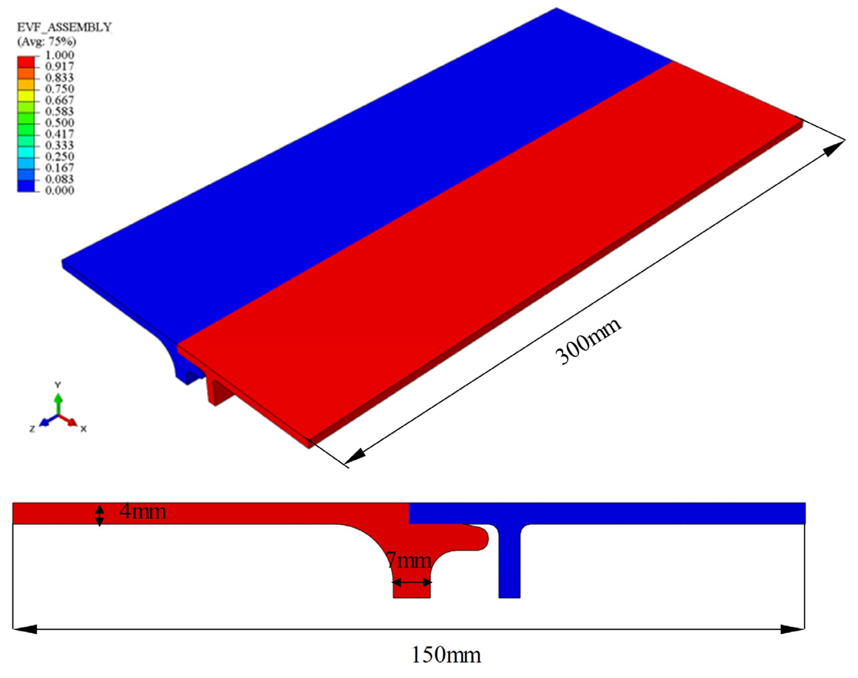
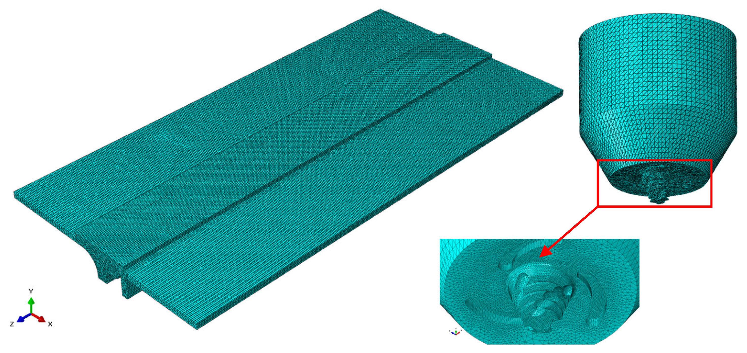
In this work, AA6005-T6 aluminum hollow extrusions with a nominal thickness were utilized for experimental validation. The equipment employed in the experiment was a FOOKE FSW150-type gantry FSW machine. The tool was made of H13 steel. The shoulder diameter of the tool was 20 mm, the root diameter of the probe was 7 mm, and the length of the probe was 4.8 mm. Right-handed thread was machined on the pin side, and three spiral grooves were added to the internal concave shoulder.
During the welding process, the tool’s tilting angle was 2.5° and the shoulder plunge depth was 0.2 mm. Welding parameters included a rotational speed of 2000 rpm and a translational speed of 1500 mm/min. Post-welding, the metallographic samples were taken in the direction of the vertical weld by an electric spark cutting machine and the metallographic samples were polished and etched with Keller reagent (2 mL HF + 3 mL HCl + 5 mL HNO3 + 190 mL H2O) to prepare metallographic specimens. Optical microscopy was used to observe the interface defects morphology of the butt–lap joint, and the heights of the hook defects were marked. Axial force data during the welding process were collected every 0.1 s by a sensor integrated into the equipment.

3. Modeling Details

The local finite element model of the butt–lap joint was established by Abaqus 2021 to simulate the hook defects of AA6005-T6 aluminum alloy in the process of FSW. In the CEL model, the entire workpiece model is initially created and set as a Eulerian body. It is then divided into two parts, with each part being assigned specific material properties. The contact between these two parts is modeled using the general contact approach to simulate the interactions between them during the actual welding process. The size of the workpiece is 300 × 150 mm and the thickness is 4 mm. The Eulerian partition is shown in Figure 1.
The tool has been accurately modeled based on its real geometry and inclined at an angle of 2.5°. The rotation and movement of the tool are precisely controlled by defining reference points coupled to the tool, enabling accurate control over tool movements. The interaction between the tool and the workpiece adheres to the Coulomb friction law.
In the process of friction stir welding, the material will experience large temperature changes and drastic plastic deformation. Therefore, it is necessary to accurately describe the relationship between the plastic strain, strain rate, and flow stress at different temperatures. Therefore, the plastic deformation of materials is described by the Johnson–Cook constitutive model, and its flow stress is given by
σ = A + B ε n 1 + C ε ˙ ε ˙ 0 1 T T r o o m T m e l t T r o o m m
where Troom and Tmelt stand for the ambient temperature and material melting temperature, respectively. ε is the effective plastic strain, ε ˙ is the strain rate, and ε ˙ 0 is the reference strain-rate (1.0 s−1). A, B, C, m, and n are material constants, and the constants for AA6005-T6 are listed in Table 1. Other temperature-dependent material properties are shown in Table 2; the material parameters used by the tool are shown in Table 3.
The heat sources in FSW come from plastic heat and friction heat, as expressed in Equation (2). The plastic heat is controlled by the product of stress and strain rate, as expressed in Equation (3). The inelastic heat fraction, denoted as η, has a defined value of 0.9, signifying that 90% of the energy produced by the material’s deformation is transformed into heat. The friction heat is controlled by the product of tangential stress ( τ ) and the slip rate ( γ ) as expressed in Equation (4). is the frictional heat factor; its value is defined as 1, indicating that all the work done by friction is converted to heat. The temperature distribution in the whole welding process is controlled by Fourier’s law, as expressed in Equation (5). The contact state between the tool and the workpiece follows the Coulomb friction law, and the friction coefficient is 0.2.
q ˙ = q ˙ p + q ˙ f
q ˙ p = η σ · ε ˙
q ˙ f = τ · γ
k 2 T + q ˙ = ρ c T t
In this model, the heat is exchanged between the workpiece and the environment. The convective heat transfer coefficient between the workpiece and the air is low, while the convective heat transfer coefficient between the workpiece bottom and the fixture is high. The specific heat dissipation values are displayed in Table 4.
During the welding process, the heat distribution between the workpiece and the tool is calculated according to the following equation:
f w = k ρ c p w k ρ c p w + k ρ c p t  
The subscripts w and t denote the workpiece and the tool, respectively. f w represents the heat transferred to the workpiece. Its value is 0.75, meaning that 75% of the total heat is transferred to the workpiece and the remaining 25% goes to the tool.
The material region was meshed using eight-node thermally coupled Eulerian elements (EC3D8RT). In order to optimize computational efficiency, the material region welding area is discretized into a finer element (1 mm), while the remaining area is divided into a coarser element (4 mm), resulting in a total of 400,000 elements, as shown in Figure 2. The tool is divided by a four-node thermally coupled tetrahedral element with a global mesh size of 1 mm and a probe mesh size of 0.2 mm and a total of 340,712 elements.

4. Results and Discussion

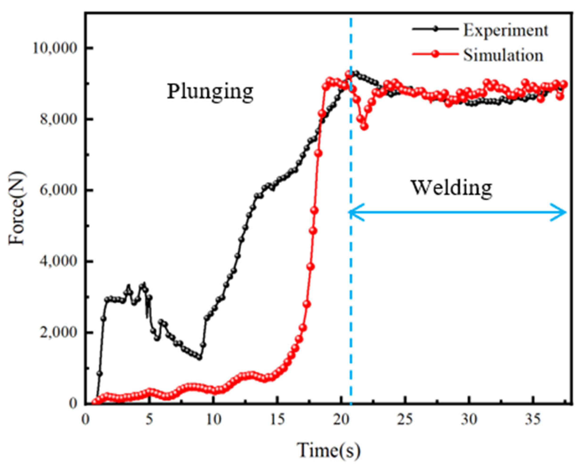
4.1. Validation of Model

Figure 3 presents axial force data obtained through numerical simulations and experiments under a welding speed of 2000 RPM and a travel speed of 1500 mm/min. The good agreement between the two curves demonstrates preliminary validation of the model. At the beginning of welding, the axial force rapidly increases as the probe initially comes into contact with the cold workpiece. As the tool rotates at high speed, the temperature in the welding area increases, causing the material in the stir zone to soften and the axial force to decrease. At t = 17 s, the tool is fully inserted into the workpiece. The shoulder begins to make contact with the surface of the workpiece and moves downward, increasing the contact area and, thus, the axial force rises again. By t = 20 s, as the tool moves forward, the welding enters a steady phase, and the axial force stabilizes, fluctuating around 9000 N. To compare the experimental and simulation results, we specifically focused on two key aspects: the morphology of the weld nugget and the size and shape of the hook defects at the lap interface. By precisely measuring the cross-sections of the welded joints in experiments and comparing these with the simulation results, we validated the effectiveness of the model. This is the first time numerical simulation methods were used to present the morphology and size of hook defects. The comparison results show that the existing model can accurately describe the shape of the plastic deformation zone, as well as the size and deflection direction of hook defects. The error between the simulation results and the experimental results is only 10.2%, as shown in Figure 4. The black lines at the plastic deformation zone and the lap surface represent the boundary of the Euler domain, showing the deformation of the material in the Euler domain.

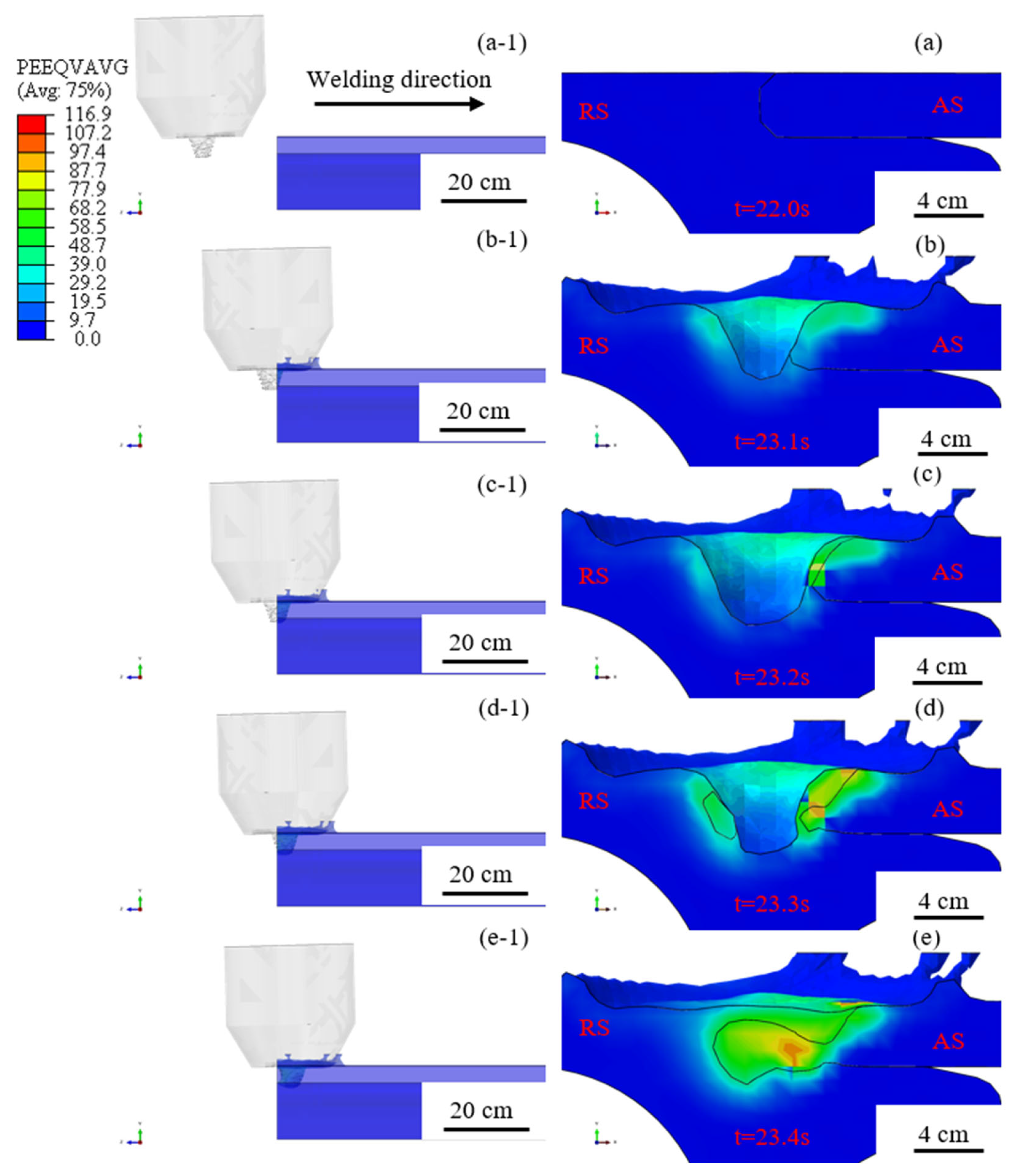
4.2. Hook Formation Process

The strain field of the section at different times was obtained using ABAQUS’s internal slicing command to analyze the formation process of the hook defects at the lap interface.
To demonstrate the continuous deformation process of the lap interface, the welding process of a certain cross-section in the model is divided into five different moments to observe the evolution of the lap interface pre- and post-welding. The formation process of the hook defects during the welding procedure is illustrated in Figure 5. Figure 5a–e shows the continuous evolution of the lap interface at different moments, while Figure 5(a-1)–(e-1) illustrates the relative position of the probe and the cross-section at different moments. The tool rotates counterclockwise, with the advancing side positioned on the lap surface. In the initial state of welding (t = 22.0 s), the lap interface does not initially make contact with the probe, and the lap surface is a flat straight line, as shown in Figure 5a. At the second moment (t = 23.1 s), the root of the probe makes contact with the material. At this time, the butt interface disappears and the lap interface near the plastic deformation zone noticeably bends upward, while the distant lap interface remains flat, as shown in Figure 5b. At the third moment (t = 23.2 s), the entire probe is in contact with the material, and the plastic deformation zone expands. The lap interface in the stir zone disappears under the action of the probe, while the lap interface at the edge of the plastic deformation zone exhibits an upward-bent shape, as shown in Figure 5c. At the fourth moment (t = 23.3 s), the upward bending degree of the lap interface near the plastic deformation zone increases further, as shown in Figure 5d. At the fifth moment (t = 23.0 s), the probe completely passes through the lap surface. The degree of upward bending of the lap interface located at the edge of the plastic deformation zone on the forward side continues to increase, while the distant lap interface remains flat, as shown in Figure 5e.
Based on the above analysis, the evolution of the hook defects can be summarized as follows: when the probe contacts the lap interface, the lap interface begins to deflect, and the interface defects begins to form. At this time, the height of the hook defects is relatively low. As the welding process continues, the interaction between the interface defects and the probe intensifies, leading to a steady increase in the height of the hook defects. Ultimately, the height of the hook defects peaks when the probe fully penetrates the lap interface.

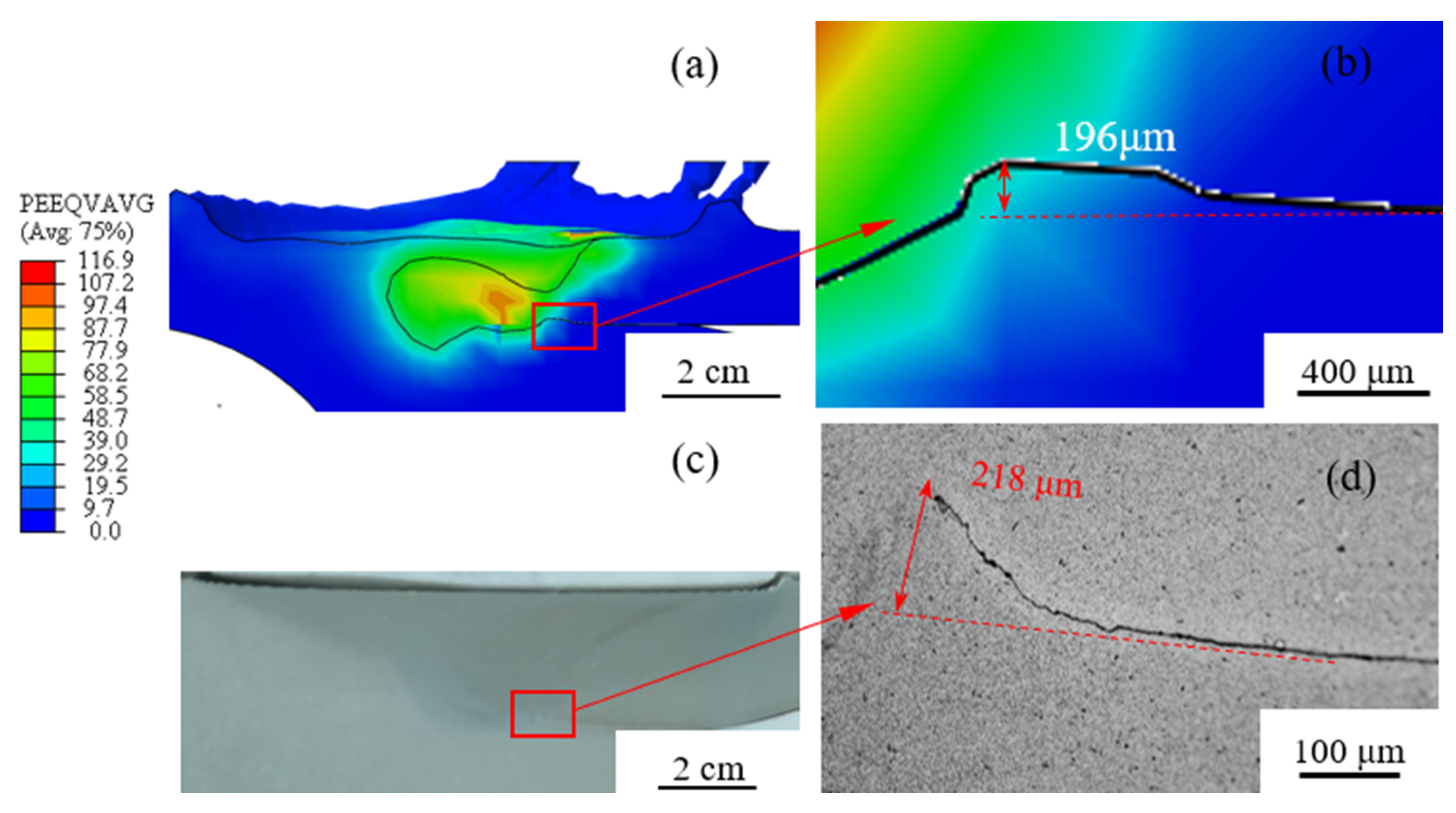
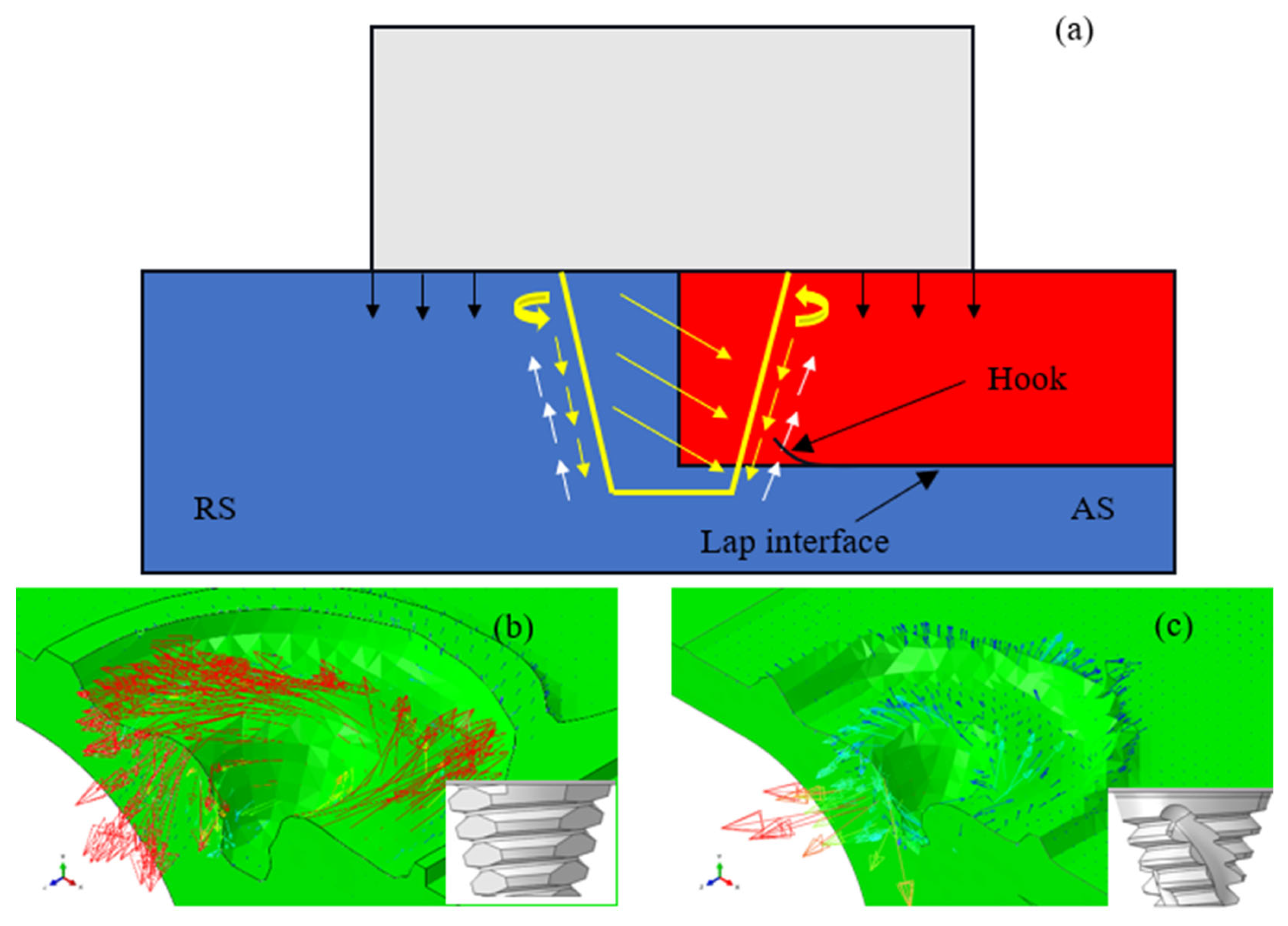
4.3. Formation Mechanism of Hook Defects

In order to investigate the causes of hook defects, the formation mechanism of hook defects was studied through numerical simulation, as shown in Figure 6. As depicted in Figure 6a,b, before the probe comes into contact with the lap surface, the lap interface in front of the probe remains flat; when the probe passes through the lap interface, the lap interface behind the probe undergoes plastic deformation and forms hook defects. The effects of temperature and force on the plastic metal are two factors that generate hook defects. Before the probe passes through the lap surface, the highest temperature at the lap interface is 278.4 °C, and after the probe passes through the lap surface, the highest temperature at the interface reaches 336.3 °C, as shown in Figure 6c,d. However, temperature is not the most fundamental factor affecting the generation of the hook. This is because the increase in the material’s temperature will only significantly reduce its yield stress; it will not cause plastic deformation of the material. The force driving the plastic metal is the main reason for the production of the hook. Before the probe passes through the lap interface, the plastic metal in front of the probe flows from the advancing side (AS) to the retreating side (RS) under the action of the probe, as shown in Figure 6e. When the probe passes through the lap interface, a large amount of plastic metal behind the probe is forced to move from the upper part of the retreating side to the bottom of the advancing side under the action of the probe (the red arrow part in the figure), and the lap interface naturally flows upward under the extrusion of the probe (the red circle part in the figure) to form the hook defects, as shown in Figure 6f.
In essence, the generation of the hook is attributed to the threads on the probe, which facilitate the migration of plastic metal material in the thickness direction, and this part of the plastic metal is squeezed by the probe, causing the vertical upward flow of the lap interface.
During the FSW process, the friction and stirring action between the tool and the workpiece generate heat, which softens the metal. The rotation of the tool induces the flow of plasticized metal. Figure 7a shows the direction of plastic metal flow at the cross-section of the joint. The plastic metal flow at the bottom of the lap interface is divided into two parts: in the shoulder action area, the plastic metal flow first rotates around the shoulder and then flows downward around the probe, pushing the plastic metal flow into the probe action area; under the compressive force of the probe and shoulder, the plastic metal flow in the probe action area moves downward and concentrates at the bottom of the weld zone. As the FSW process progresses, the accumulated amount of plasticized metal at this location increases, as does the pressure. Therefore, the lower layer of plastic metal flow tends to move upward and then forming hook defects.
According to the material flow field shown in Figure 7b, due to the addition of a planar structure, TPP significantly increases the material flow speed in the horizontal direction, while the reduction in thread structure decreases the migration of plasticized metal in the thickness direction. This reduction weakens the accumulation and compressive action of plasticized metal at the lap interface, resulting in smaller interface defects. However, it also leads to the formation of void defects due to an insufficient flow of plasticized metal in the thickness direction. On the other hand, in Figure 7c, RLP, which has an increased thread structure, enhances the migration of plasticized metal in the thickness direction. The left-handed groove structure prevents the excessive accumulation of plasticized metal at the lap interface, thereby producing smaller interface defects and also avoiding the formation of void defects.

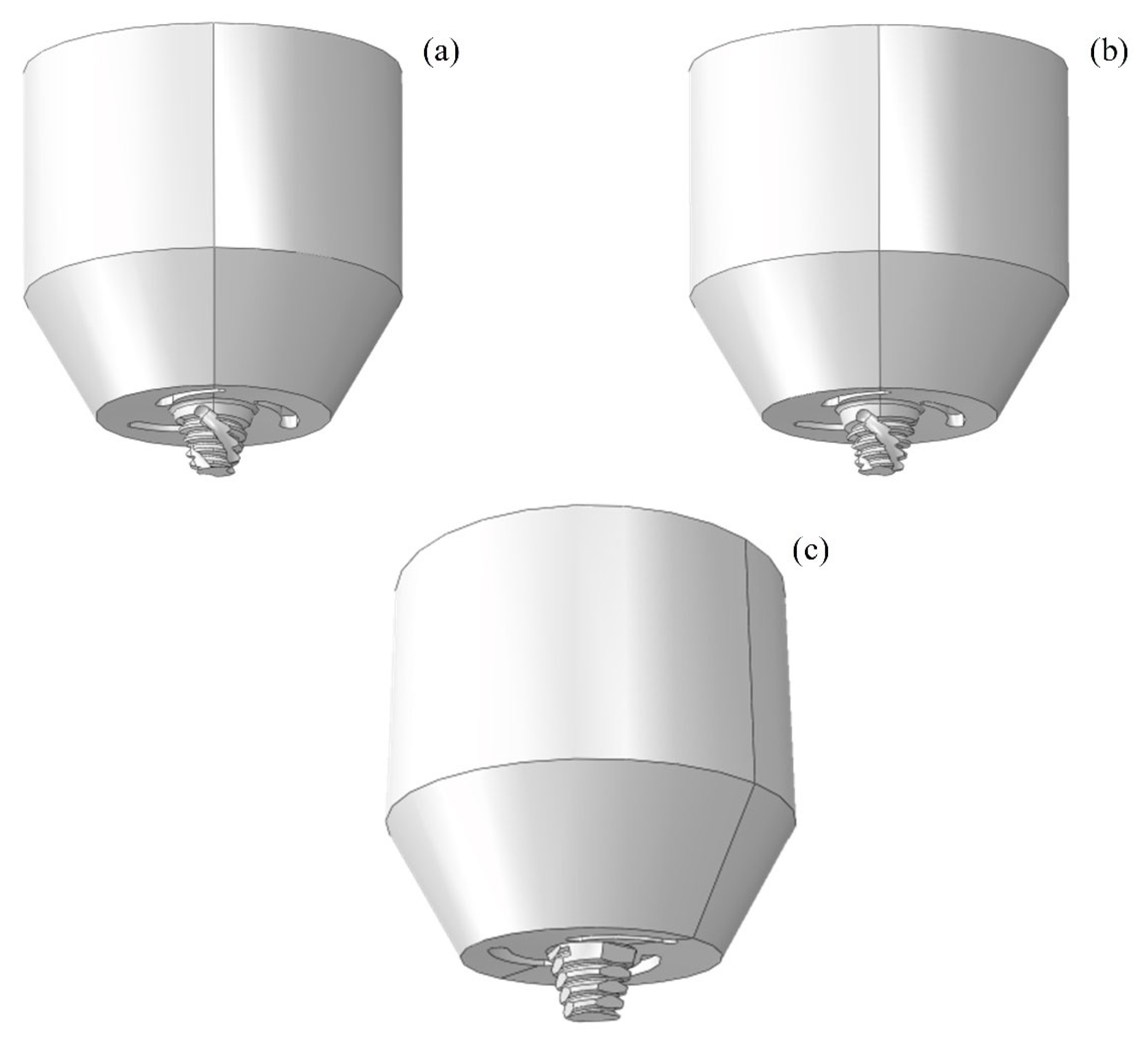
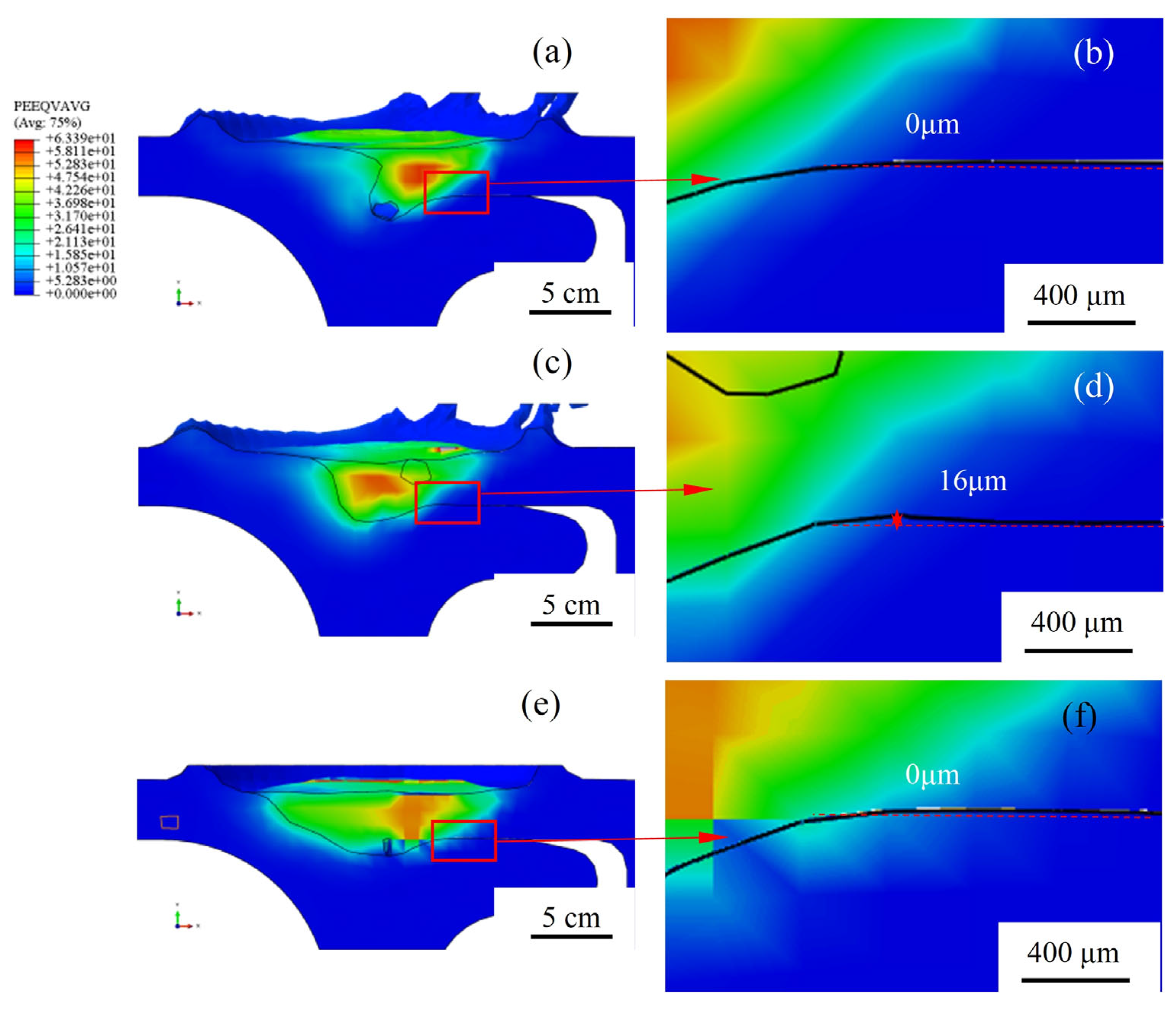
4.4. The Impact of Three Probes on Hook Defects

Based on the above analysis, the hook defects are caused by the threaded structure on the probe, which promotes material migration in the thickness direction. Therefore, by changing the direction of the threads and grooves on the probe or reducing the amount of threaded structure, the migration of plastic metal in the thickness direction can be minimized, thus decreasing the size of the hook defects. The probe that only changes the direction of the grooves is called a right–left probe (RLP), while a probe that changes the direction of both the threads and grooves is called a left–left probe (LLP), and one that adds a three-plane structure is called a three-plane probe (TPP). The morphology of the three probes is shown in Figure 8.
The influence of the three types of probes on the hook defects was predicted by numerical simulation, and the simulation results are shown in Figure 9. By observing the equivalent strain field, we note that all three types of probes can significantly reduce the height of the hook defects. The RLP probe achieved a hook defects size of only 16 μm at the lap interface, while the LLP and TPP nearly eliminated the hook defects at the lap interface, with sizes reaching almost 0 μm. However, both the LLP and TPP under high-speed welding conditions produced void defects at the bottom of the plastic deformation zone, which severely affected the quality of the joint. The left-handed groove structure on the probe not only promotes the flow of plastic metal material but also reduces the amount of plastic metal migrating in the thickness direction. This reduction in migration diminishes the accumulation of plastic metal at the bottom of the plastic deformation zone, thereby producing smaller hook defects sizes. However, when both the groove and thread are changed to a left-handed orientation, it can lead to insufficient plastic metal flow, resulting in void defects at the bottom of the plastic deformation zone. Additionally, the planar structure on the probe enhances the horizontal flow of plastic metal, increasing the volume of the plastic deformation zone. However, this increase in planar structure, coupled with a reduction in threaded structure, leads to insufficient migration of plastic metal material in the thickness direction. Although this configuration prevents the formation of hook defects at the lap interface, it also results in the creation of small-sized void defects at the bottom of the stir zone.
To test whether the tool meets the design requirements, the RLP was fabricated and subjected to corresponding FSW experiments. The welding process parameters were set as follows: a welding speed of 2000 rpm and a travel speed of 1500 mm/min. Figure 10 shows the cross-sectional morphology of the stir zone and the size of the hook defects at the lap interface produced by the RLP. The experimental results are largely consistent with those obtained from the simulations. The joint with the RLP tool has a well-formed internal structure and produces smaller hook defects at the lap interface, with the size of the defects reduced to 58 μm.

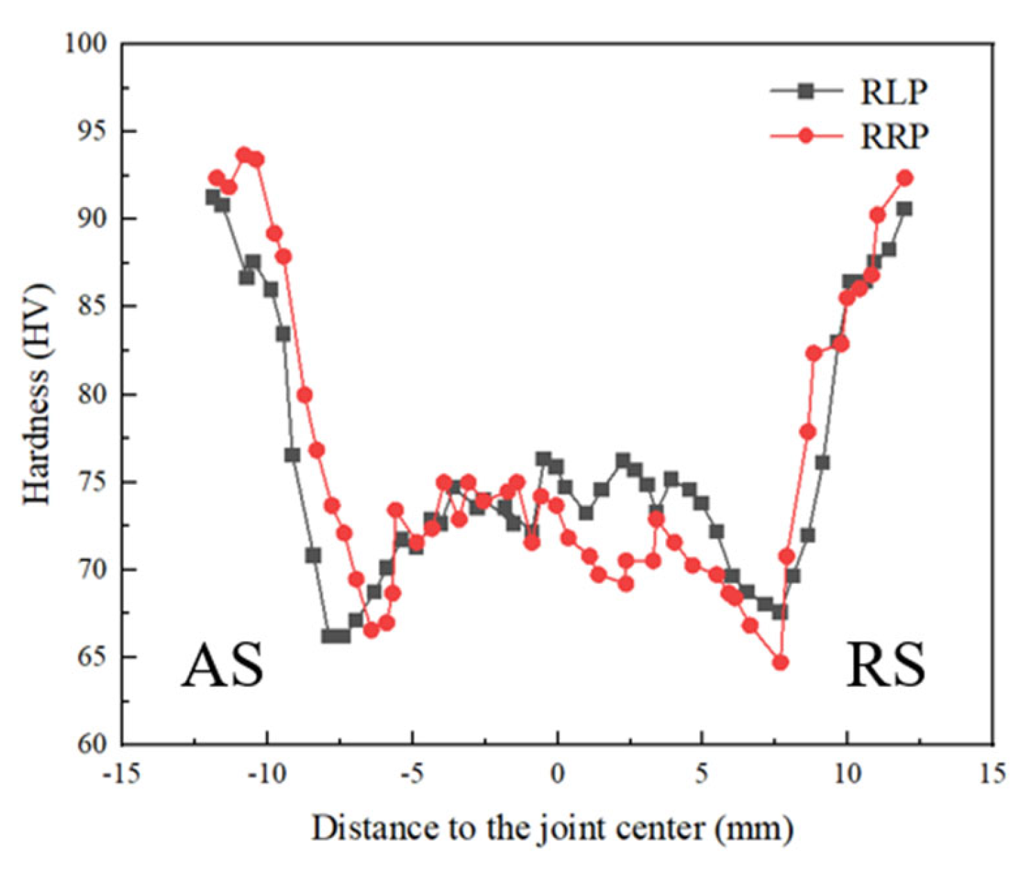
4.5. Mechanical Properties of the Butt–Lap Joints

Figure 11 illustrates the microhardness distribution on the cross-section of butt–lap joints under the same parameters using RRP and RLP. The hardness of the joints significantly softened, displaying a typical W-shaped hardness distribution across the joint. The lowest hardness values were found on the retreating side, with the lowest microhardness in the heat-affected zone being only 64 Hv. The hardness was relatively higher in the base metal, but there was a significant decline as it transitioned towards the weld zone, across both the thermo-mechanical-affected zone and the heat-affected zone, followed by a recovery in hardness within the weld zone. This pattern arose because the grains in the heat-affected zone underwent growth due to the high-temperature thermal cycles, while some grains in the thermo-mechanical-affected zone recrystallized due to the compressive action of the plastic metal, resulting in a mixed grain size in this area and severe grain deformation. These microstructural changes led to a substantial decrease in the strength and hardness of the joints. The grains in the weld zone underwent recrystallization due to the intense stirring action of the probe, resulting in grain refinement, thereby improving the strength and hardness to some extent.
Figure 12 presents the tensile shear results for butt–lap joints made of 6005A-T6 aluminum alloy. The tensile strength of the parent material was 252 MPa. The joints using the RRP achieved a tensile strength of 189.27 MPa, which is 75.1% of the base metal’s strength; meanwhile, joints using the RLP showed a tensile strength of 194.06 MPa, reaching 77% of the base metal’s strength. The reduction in the size of hook defects led to an improvement in the tensile strength of the joints.

5. Conclusions

In this study, we explored the efficacy of three distinct probe designs to reduce hook defects in the FSW of AA6005-T6 aluminum alloy. The research was underpinned by both extensive numerical simulations and experimental validations, providing a robust framework for understanding the mechanisms behind hook defects formation and mitigation. Our findings confirm that probe design plays a crucial role in influencing the dynamics of material flow during the welding process, which in turn affects the formation and magnitude of hook defects. The RLP, LLP, and TPP each demonstrated varying degrees of success in minimizing these defects:
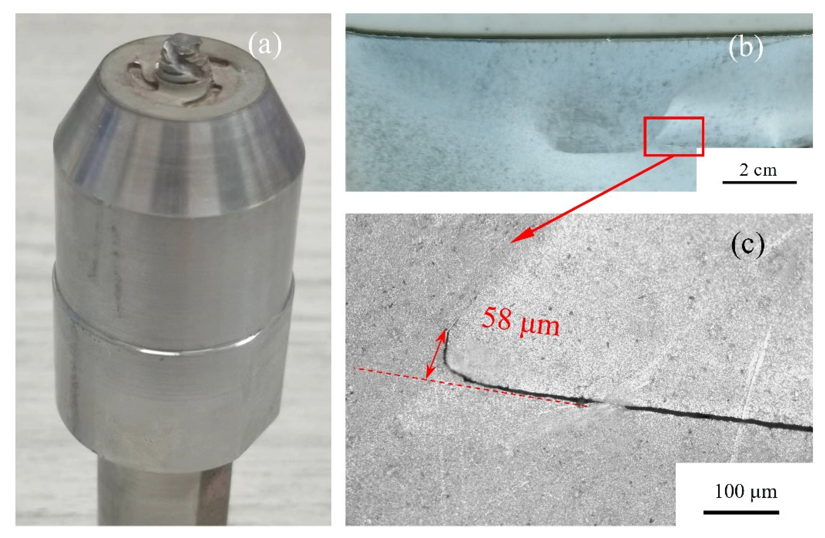
  • The RLP was effective in reducing the size of the hook defects to 58 μm without introducing internal voids, making it a viable option for enhancing joint quality without compromising structural integrity.
  • The LLP and TPP almost eliminated the hook defects at the lap interface, achieving defect sizes close to 0 μm. However, these designs were also associated with the formation of void defects under high-speed welding conditions, which could potentially degrade the joint quality.

Author Contributions

Conceptualization, P.D.; methodology, P.D. and G.B.; software, G.B. and L.Q.; validation, L.Q. and G.B.; investigation, P.D.; resources, P.D.; data curation, L.Q.; writing—original draft preparation, L.Q.; writing—review and editing, P.D., K.L. and H.Z.; visualization, G.B.; supervision, P.D., K.L. and H.Z.; project administration, P.D.; funding acquisition, P.D. All authors have read and agreed to the published version of the manuscript.

Funding

This research received no external funding.

Data Availability Statement

The original contributions presented in the study are included in the article. Further inquiries can be directed to the corresponding authors.

Acknowledgments

The authors thank CRRC Tangshan Co., Ltd. for providing financial support to this work, and thank Xujing Niu for conducting the FSW experiments.

Conflicts of Interest

The authors declare no conflict of interest.

References

  1. Meng, X.; Huang, Y.; Cao, J.; Shen, J.; dos Santos, J.F. Recent progress on control strategies for inherent issues in friction stir welding. Prog. Mater. Sci. 2021, 115, 100706. [Google Scholar] [CrossRef]
  2. Singh, V.P.; Patel, S.K.; Ranjan, A.; Kuriachen, B. Recent research progress in solid state friction-stir welding of aluminium–magnesium alloys: A critical review. J. Mater. Res. Technol. 2020, 9, 6217–6256. [Google Scholar] [CrossRef]
  3. Liu, X.; Liu, H.; Wang, T.; Wang, X.; Yang, S. Correlation between microstructures and mechanical properties of high-speed friction stir welded aluminum hollow extrusions subjected to axial forces. J. Mater. Sci. Technol. 2018, 34, 102–111. [Google Scholar] [CrossRef]
  4. Ji, S.; Li, Z. Reducing the Hook Defect of Friction Stir Lap Welded Ti-6Al-4V Alloy by Slightly Penetrating into the Lower Sheet. J. Mater. Eng. Perform. 2017, 26, 921–930. [Google Scholar] [CrossRef]
  5. Xu, X.; Yang, X.; Zhou, G.; Tong, J. Microstructures and fatigue properties of friction stir lap welds in aluminum alloy AA6061-T6. Mater. Des. 2012, 35, 175–183. [Google Scholar] [CrossRef]
  6. Chen, H.; Fu, L.; Liang, P.; Liu, F. Defect features, texture and mechanical properties of friction stir welded lap joints of 2A97 Al-Li alloy thin sheets. Mater. Charact. 2017, 125, 160–173. [Google Scholar] [CrossRef]
  7. Song, Y.; Yang, X.; Cui, L.; Hou, X.; Shen, Z.; Xu, Y. Defect features and mechanical properties of friction stir lap welded dissimilar AA2024–AA7075 aluminum alloy sheets. Mater. Des. 2014, 55, 9–18. [Google Scholar] [CrossRef]
  8. Trimech, M.; Annan, C.D.; Walbridge, S.; Maljaars, J. Fatigue behaviour of butt-lap friction stir welded joints used with aluminum bridge decks. Structures 2023, 51, 1795–1805. [Google Scholar] [CrossRef]
  9. Fersini, D.; Pirondi, A. Fatigue behaviour of Al2024-T3 friction stir welded lap joints. Eng. Fract. Mech. 2007, 74, 468–480. [Google Scholar] [CrossRef]
  10. Ericsson, M.; Jin, L.; Sandstrom, R. Fatigue properties of friction stir overlap welds. Int. J. Fatigue 2007, 29, 57–68. [Google Scholar] [CrossRef]
  11. EN ISO 25239-5:2020; Friction Stir Welding—Aluminium—Part 5: Quality and Inspection Requirements. ISO: Geneva, Switzerland, 2020.
  12. Liu, H.; Hu, Y.; Peng, Y.; Dou, C.; Wang, Z. The effect of interface defect on mechanical properties and its formation mechanism in friction stir lap welded joints of aluminum alloys. J. Mater. Process. Technol. 2016, 238, 244–254. [Google Scholar] [CrossRef]
  13. Xiao, Y.; Li, Y.; Shi, L.; Wu, C.; Liu, H.; Sun, Z. Experimental and numerical analysis of friction stir additive manufacturing of 2024 aluminium alloy. Mater. Today Commun. 2023, 35, 105639. [Google Scholar] [CrossRef]
  14. Cao, X.; Jahazi, M. Effect of tool rotational speed and probe length on lap joint quality of a friction stir welded magnesium alloy. Mater. Des. 2011, 32, 1–11. [Google Scholar] [CrossRef]
  15. Tucci, F.; Carlone, P.; Silvestri, A.T.; Parmar, H.; Astarita, A. Dissimilar friction stir lap welding of AA2198-AA6082: Process analysis and joint characterization. CIRP J. Manuf. Sci. Technol. 2021, 35, 753–764. [Google Scholar] [CrossRef]
  16. Astarita, A.; Tucci, F.; Silvestri, A.T.; Perrella, M.; Boccarusso, L.; Carlone, P. Dissimilar friction stir lap welding of AA2198 and AA7075 sheets: Forces, microstructure and mechanical properties. Int. J. Adv. Manuf. Technol. 2021, 117, 1045–1059. [Google Scholar] [CrossRef]
  17. Badarinarayan, H.; Shi, Y.; Li, X.; Okamoto, K. Effect of tool geometry on hook formation and static strength of friction stir spot welded aluminum 5754-O sheets. Int. J. Mach. Tools Manuf. 2009, 49, 814–823. [Google Scholar] [CrossRef]
  18. Yue, Y.; Li, Z.; Ji, S.; Huang, Y.; Zhou, Z. Effect of Reverse-threaded Pin on Mechanical Properties of Friction Stir Lap Welded Alclad 2024 Aluminum Alloy. J. Mater. Sci. Technol. 2016, 32, 671–675. [Google Scholar] [CrossRef]
  19. Zhang, Y.; Huang, Y.; Meng, X.; Li, J.; Xie, Y.; Fan, Q. Friction stir lap welding of AA2024-T4 with drastically different thickness. Int. J. Adv. Manuf. Technol. 2020, 106, 3683–3691. [Google Scholar] [CrossRef]
  20. Salari, E.; Jahazi, M.; Khodabandeh, A.; Ghasemi-Nanesa, H. Influence of tool geometry and rotational speed on mechanical properties and defect formation in friction stir lap welded 5456 aluminum alloy sheets. Mater. Des. 2014, 58, 381–389. [Google Scholar] [CrossRef]
  21. Baratzadeh, F.; Boldsaikhan, E.; Nair, R.; Burford, D.; Lankarani, H. Investigation of mechanical properties of AA6082-T6/AA6063-T6 friction stir lap welds. J. Adv. Join. Process. 2020, 1, 100011. [Google Scholar] [CrossRef]
  22. Meng, X.; Cao, B.; Qiu, Y.; Chen, H.; Xie, Y.; Wan, L.; Huang, Y. Equal-load-bearing joining of alclad AA2024-T4 alloy stringers and skins in aviation via friction stir lap welding. J. Manuf. Process. 2021, 68, 1295–1302. [Google Scholar] [CrossRef]
  23. Xiao, X.; Qin, D.; Mao, Y.; Fu, L. Effects of pin morphology on the interface defects of the FSWed lap joints of 2A12 aluminum alloy. J. Manuf. Process. 2021, 68, 128–140. [Google Scholar] [CrossRef]
  24. Chen, K.; Liu, X.; Ni, J. Thermal-mechanical modeling on friction stir spot welding of dissimilar materials based on Coupled Eulerian-Lagrangian approach. Int. J. Adv. Manuf. Technol. 2016, 91, 1697–1707. [Google Scholar] [CrossRef]
  25. Chu, Q.; Yang, X.W.; Li, W.Y.; Vairis, A.; Wang, W.B. Numerical analysis of material flow in the probeless friction stir spot welding based on Coupled Eulerian-Lagrangian approach. J. Manuf. Process. 2018, 36, 181–187. [Google Scholar] [CrossRef]
  26. Geng, P.; Ma, Y.; Ma, N.; Ma, H.; Aoki, Y.; Liu, H.; Fujii, H.; Chen, C. Effects of rotation tool-induced heat and material flow behaviour on friction stir lapped Al/steel joint formation and resultant microstructure. Int. J. Mach. Tools Manuf. 2022, 174, 103858. [Google Scholar] [CrossRef]
  27. Peng, Y.; Chen, X.; Peng, S.; Chen, C.; Li, J.; Liu, G. Strain Rate-Dependent Constitutive and Low Stress Triaxiality Fracture Behavior Investigation of 6005 Al Alloy. Adv. Mater. Sci. Eng. 2018, 2018, 2712937. [Google Scholar] [CrossRef]
  28. Simar, A.; Bréchet, Y.; de Meester, B.; Denquin, A.; Gallais, C.; Pardoen, T. Integrated modeling of friction stir welding of 6xxx series Al alloys: Process, microstructure and properties. Prog. Mater. Sci. 2012, 57, 95–183. [Google Scholar] [CrossRef]
Figure 1. The material distribution of the butt–lap structure.
Metals 14 00653 g001
Figure 2. Meshing of workpiece and tool.
Metals 14 00653 g002
Figure 3. Comparison of experimental and simulated results of axial force.
Metals 14 00653 g003
Figure 4. Comparison of the simulated hook size and the experimental results. (a) Simulation result of hook defects. (b) Partial enlarged view of hook defects simulation results. (c) Hook defects experimental results. (d) Partial enlarged view of hook defects experimental results.
Metals 14 00653 g004
Figure 5. Hook defects formation process. (a-1) The position of the probe relative to the cross section at t = 22.0 s (b-1) The position of the probe relative to the cross section at t = 23.1 s (c-1) The position of the probe relative to the cross section at t = 23.2 s (d-1) The position of the probe relative to the cross section at t = 23.3 s (e-1) The position of the probe relative to the cross section at t = 23.4 s (a) Hook defect morphology at t = 22.0 s (b) Hook defect morphology at t = 23.1 s (c) Hook defect morphology at t = 23.2 s (d) Hook defect morphology at t = 23.3 s (e) Hook defect morphology at t = 23.4 s.
Metals 14 00653 g005
Figure 6. Schematic diagram of hook defects formation mechanism. (a) Relatively flat interface topography features (b) Hook defect formation (c) The interface temperature is 278.4 ° C (d) The interface temperature is 336.3 ° C (e) Velocity field at the lap surface before the probe (f) Velocity field at the lap surface behind the probe.
Metals 14 00653 g006
Figure 7. (a) Schematic diagram of plastic metal flow in FSW. (b) Flow field of a three-plane probe (c) Flow field of a right–left probe.
Metals 14 00653 g007
Figure 8. FSW tools (a) left–left probe (LLP), (b) right–left probe (RLP), (c) three-plane probe (TPP).
Metals 14 00653 g008
Figure 9. Simulation results of two types of probe (a) the LLP, (b) the size of hook defects, (c) the RLP, (d) the size of hook defects. (e) the TTP (f) the size of hook defects.
Metals 14 00653 g009
Figure 10. Experimental results of two types of tool. (a) actual image of the tool. (b) Macro appearance of weld (c) the size of hook defects.
Metals 14 00653 g010
Figure 11. Microhardness distribution of the cross-section with different probe.
Metals 14 00653 g011
Figure 12. Influence of probe on experimental weld strength.
Metals 14 00653 g012
Table 1. Material constant of Johnson–Cook model Reprinted from Ref. [27].
A (MPa)B (MPa)CnTroom (°C)
255.25411.690.01860.8224
Table 2. Thermal properties used for the AA6005-T6 alloy as a function of temperature Reprinted from Ref. [28].
Temperature, T (°C)Density, ρ (kg·m−3)Specific Heat, cp (J·kg−1·K−1)Thermal Conductivity, (W·m−1 K−1)
252680--
502680920206.6
1002670930208.3
1502660950210.3
2002650970210.3
2502630990210.9
30026201010208.6
35026101020205.6
40026001040201.9
45025901060197.5
50025801080190.0
550-1110182.8
Table 3. Physical and mechanical properties of H13 steel.
ParameterParameter ValuesTemperature (°C)
Density, ρ (kg·m−3)7800-
Young’s modulus (GPa)20720
20093
186300
158540
Poisson’s ratio0.3-
Thermal conductivity (W·m−1 K−1)17.627
23.4214
25.2437
26.8659
Specific heat (J·kg−1·K−1)43020
470100
521200
571300
621400
673500
722600
Expansion coefficient (10−6 m/m·°C)10.4103
11.3214
12.4306
13.1417
13.5548
Table 4. Convective heat transfer coefficient between workpiece and environment.
Coefficient of Bottom-Convection Heat Transfer (W/m2·°C)Air Convection Heat Transfer Coefficient (W/m2·°C)Ambient Temperature (°C)
5001025
Disclaimer/Publisher’s Note: The statements, opinions and data contained in all publications are solely those of the individual author(s) and contributor(s) and not of MDPI and/or the editor(s). MDPI and/or the editor(s) disclaim responsibility for any injury to people or property resulting from any ideas, methods, instructions or products referred to in the content.

