Abstract
This paper aims to investigate the response and local buckling of locally sharp-notched C2700 brass circular tubes (LSN C2700 brass circular tubes) under cyclic bending loads. The study considers four different notch orientations (0°, 30°, 60°, and 90°) and five distinct notch depths (0.2, 0.4, 0.6, 0.8, and 1.0 mm). The results reveal that notch orientation and depth exert minimal impact on the moment–curvature relationship, leading to the formation of stable loops. The ovalization–curvature graphs demonstrate a trend of symmetry, serration, and growth with an increasing number of bending cycles. Additionally, larger notch orientations or smaller notch depths result in reduced ovalization. Furthermore, the double logarithmic coordinates of controlled curvature–number of cycles necessary to induce local buckling reveal five non-parallel lines representing different notch depths when the notch orientation is fixed. Finally, by adopting the formulas for smooth tubes and for locally sharp-notched 304 stainless steel circular tubes (LSN SS304 circular tubes), this study adjusts the related material parameters accordingly. These modifications effectively describe the controlled curvature–number of cycles necessary to induce local buckling for LSN C2700 brass circular tubes with different notch orientations and depths under cyclic bending, demonstrating reasonable agreement with the experimental results.
1. Introduction
Tubes are commonly subjected to prolonged cyclic bending loads, causing a gradual decrease in their strength as the cycle count increases. Simultaneously, these tubes undergo ovalization, defined as the reduction in the outer diameter (∆D) divided by the original outer diameter (Do), indicating irreversible deformation. When ΔD/Do reaches a critical value, the tube may undergo local buckling, leading to structural failure. Such failure modes can result in the tube’s inability to withstand loads, ultimately resulting in scenarios such as leakage or blockage of transported substances.
Numerous researchers have investigated the bending behavior of smooth tubes. Kyriakides and Shaw [1] developed a device capable of performing both monotonic and cyclic bending tests on tubes, with or without external pressure. This equipment has been extensively utilized in the study of tubes made from various materials, including 6061-T6 aluminum alloy, 304 stainless steel, 1018 steel, 1020 steel, and NiTi smooth tubes [1,2,3,4,5,6,7,8,9].
Several researchers have made notable contributions to the study of tube behavior under various bending conditions. For instance, Yuan and Mirmiran [10] focused on the buckling behavior of concrete-filled fiber-reinforced plastic tubes subjected to bending. Elchalakani et al. [11] conducted explorations into the slenderness limit of cold-formed hollow sections through cyclic bending tests. Additionally, Elchalakani and Zhao [12] studied the cyclic bending performance of concrete-filled cold-formed steel tubes, while Zhi et al. [13] examined the stability and instability of cylindrical shells under earthquake conditions. In a separate study, Yazdani and Nayebi [14] analyzed the damage sustained by pipelines when bending under stable internal pressure. Guo et al. [15] focused on studying the bending behavior of thin-walled hollow tubes, whereas Elchalakani et al. [16] established novel ductile slenderness limits based on strains for concrete-filled tubes through bending tests.
Other researchers have explored various aspects of tube behavior, including instability following non-proportional paths [17], the effect of corrosion on the bending performance of curved tubes [18], and local buckling behavior under bending and axial loads [19]. Additionally, Silveira et al. [20] demonstrated the applicability of the constructal law in evaluating the mechanical geometry of materials engineering systems. Montes [21] focused on the experimental study on the bending of a polyamide tube using high-power ultrasound. Shi et al. [22] found that the fracture of steel wires leads to the failure of the tube, and higher temperature has a negative effect on the tubes’ bending capacity. Chen et al. [23] experimentally and theoretically examined the flexural behavior of hollow section concrete-filled GFRP tubular (HS-CFGT) members. Lavayen-Farfan et al. [24] proposed the theoretical approach by validating with three-point bending experimental tests and an adequate agreement with experiments. He et al. [25] proposed the relationship between the bending angle and the length of the transition section formation zone through experimental and simulation verification. Wang et al. [26] conducted a four-point bending experimental study on the bending response of square steel tube concrete reinforced by internal angle steel. Meanwhile, Wu et al. [27] explored the response and damage of stacked sequentially braided composite pipes with 45° and 60° braids under three-point bending. Duda et al. [28] proposed a discrete model that can be applied to finite element analysis to model and predict the mechanical behavior of thin-walled CFRP tubes.
C2700 brass circular tubes are widely used materials in various industries, valued for their good mechanical properties, corrosion resistance, excellent machinability, and high conductivity. They serve diverse purposes in industries such as manufacturing precision instruments, hip parts, gun shells, HVAC (Heating, Ventilation, and Air Conditioning), and construction. Examples of their applications include oil–water separators for ships, tubes for transporting liquids and gases in HVAC systems, roof drainage systems, and underwater cable structures. Due to the functional requirements in these applications, C2700 brass circular tubes often undergo various machining processes, including drilling, grooving, and circumferential cutting. Consequently, this study aims to investigate the response and local buckling of LSN C2700 brass circular tubes with different notch orientations and depths under cyclic bending.
Although Lee et al. [29] conducted relevant research on the response and local buckling of LSN SS304 circular tubes with different notch orientations and depths under cyclic bending loads, questions have arisen regarding the consistency of observed behaviors in LSN C2700 brass circular tubes. These questions include the relationships of moment–curvature, ovalization–curvature, and the controlled curvature–number of cycles necessary to induce local buckling. Additionally, can the empirical formulas proposed for the locally sharp-notched SUS304 stainless steel tubes be applied to the locally sharp-notched C2700 brass circular tubes? Furthermore, this paper will thoroughly discuss the applicability of the theory they proposed to other materials.
2. Experiments
2.1. Experimental Devices
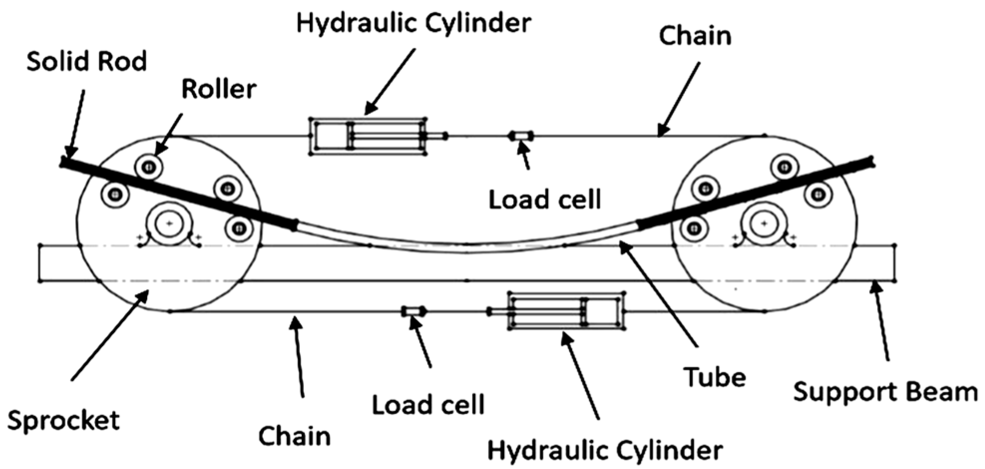
In this study, cyclic bending tests were performed on LSN C2700 brass circular tubes using a pure bending (four-point bending) machine, illustrated in Figure 1. The test setup includes two sprockets mounted on beams and a strong chain running around them, capable of accommodating tube specimens up to 1 m in length. To facilitate testing, each tube is fitted with solid rod extensions. During the bending process, the interaction between the tube and the roller allows for free axial movement. The applied load is generated by two concentrated loads from a pair of rollers. Retraction of the upper or lower cylinder initiates sprocket rotation, enabling pure bending of the test tube. Reverse bending is achieved by reversing the hydraulic circuit’s flow direction. For a more comprehensive understanding of the machine, readers are directed to the detailed exposition by Pan et al. [30].
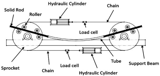
Figure 1.
Schematic diagram of the tube-bending machine.
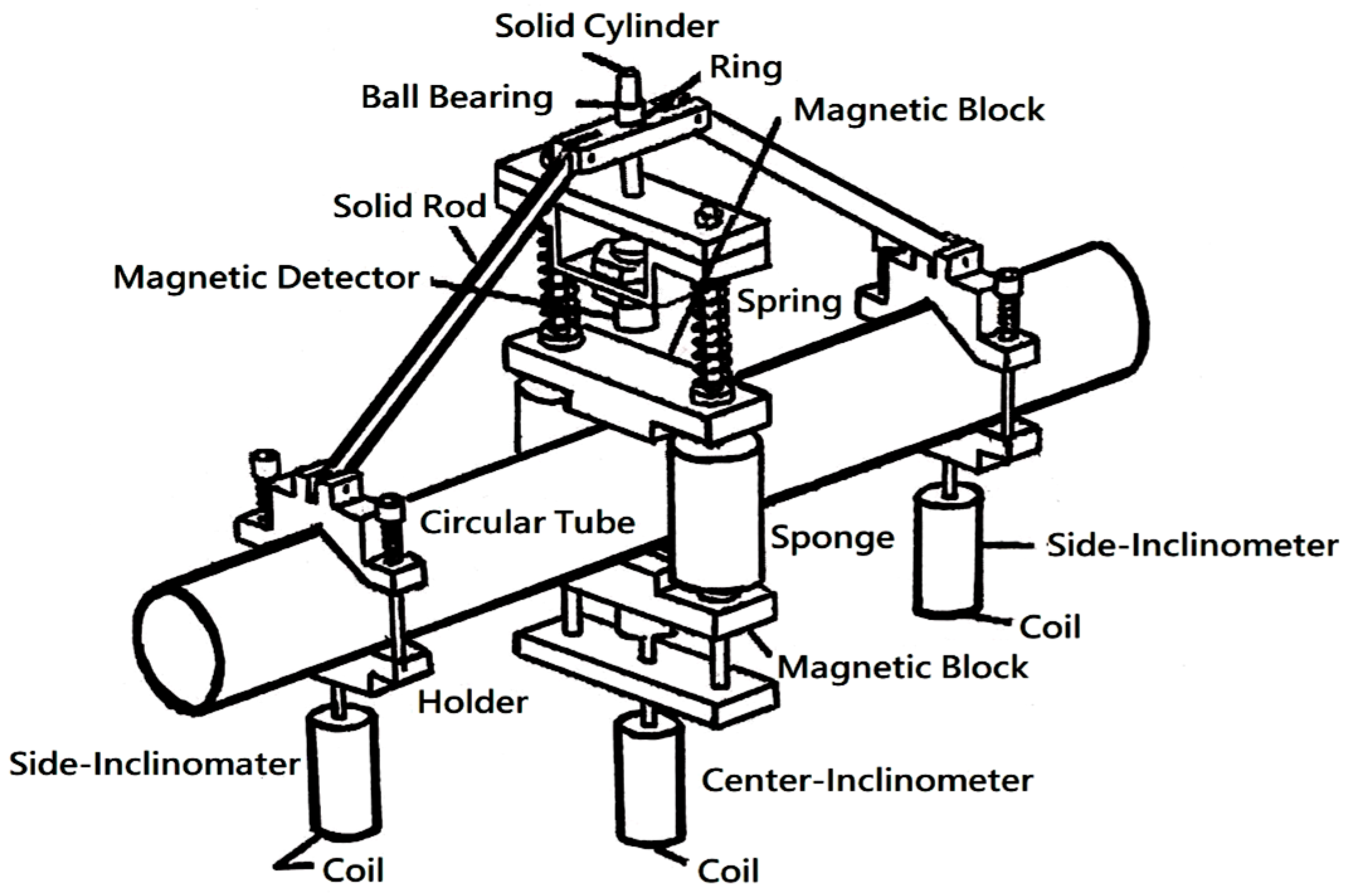
The Curvature and Ovalization Measurement Apparatus (COMA), developed by Pan et al. [30] and depicted in Figure 2, is a valuable tool for assessing tube curvature (κ) and ovalization (ΔD/Do), crucial parameters in this study. It is a lightweight instrument that can be mounted close to the tube mid-span. The COMA includes three inclinometers. Two of them, referred to as side-inclinometers, are fixed on two holders. These holders are attached to the circular tube before testing begins. The distance between the two side-inclinometers is denoted as Lo.
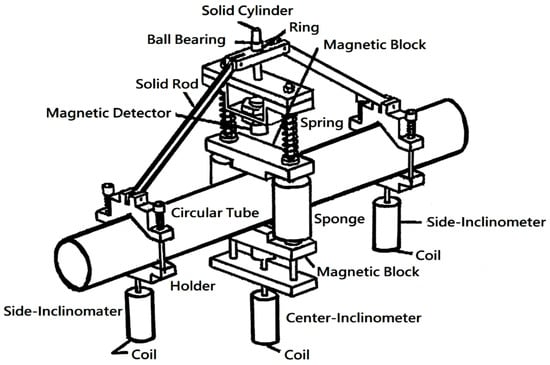
Figure 2.
Schematic diagram of the COMA.
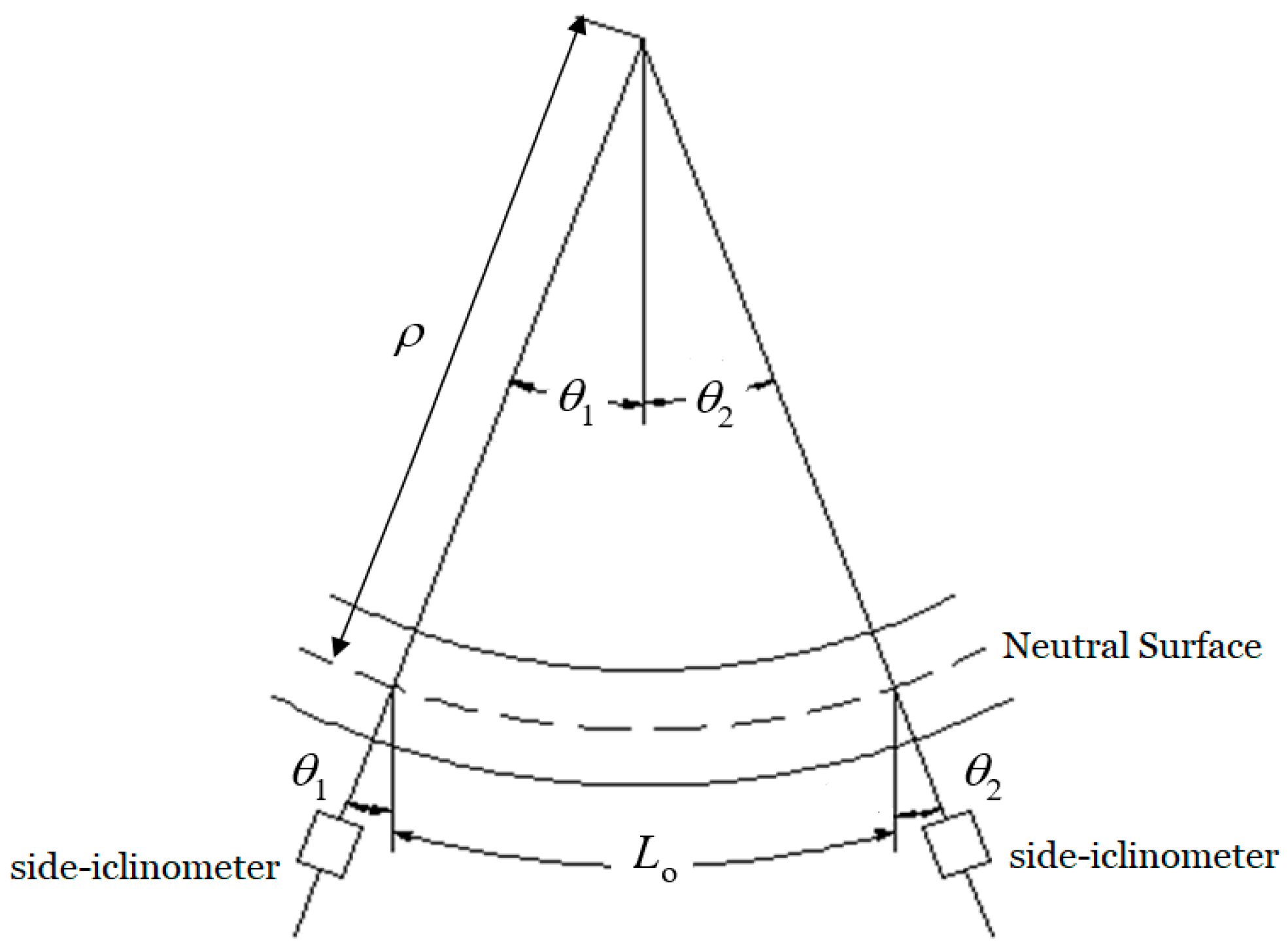
Consider that the circular tube is subjected to pure bending, as shown in Figure 3. The angle changes detected by the two side-inclinometers are denoted as θ1 and θ2. From Figure 3, the value of Lo is determined as
where ρ is the radius of the curvature. The κ is
Lo = ρ (θ1 + θ2),
κ = 1/ρ = (θ1 + θ2)/Lo
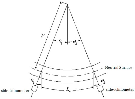
Figure 3.
Longitudinal deformation between two side-inclinometers under pure bending.
2.2. Material and Specimens
In this study, tubes fabricated from C2700 brass were utilized. The chemical composition of the tubes includes Pb (0.05%), Fe (0.05%), Zn (32.0%), and the rest is Cu. The material properties are as follows: density of 8450 kg/m3, elastic modulus of 103 GPa, Poisson’s ratio of 0.31, yield strength of 275 MPa, and ultimate strength of 380 MPa.
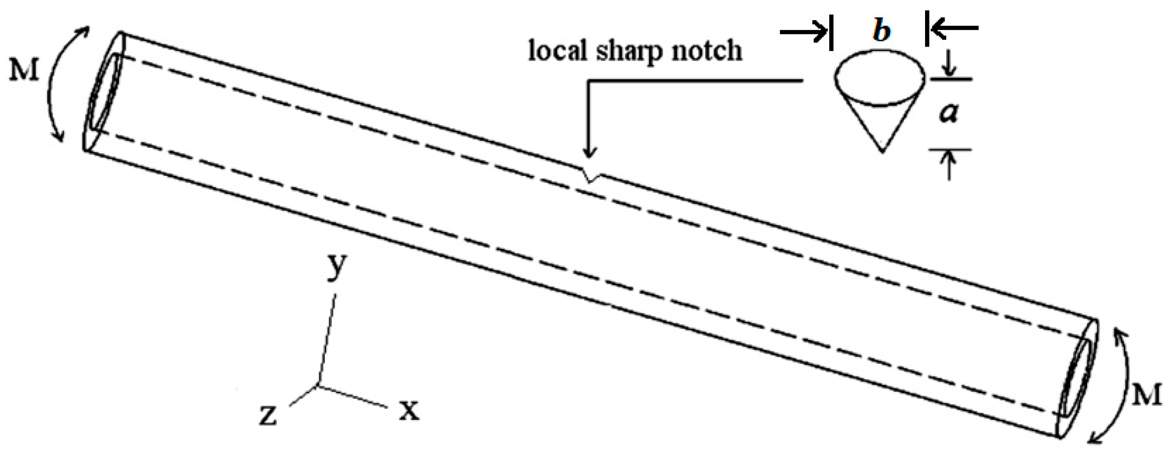
The initial, raw C2700 brass circular tubes had an outer diameter (Do) of 31.8 mm and a wall thickness (t) of 1.5 mm. To introduce local sharp notches, the raw tubes underwent drilling on the outside surface to achieve expected notch depths (a) of 0.2, 0.4, 0.6, 0.8, and 1.0 mm. Figure 4 depicts the schematic diagram of the LSN tube. Based on the drill size used, the corresponding surface width (b) of the notches was 0.6, 1.2, 1.8, 2.4, and 3.0 mm, respectively. Figure 5 provides a visual representation of the LSN C2700 brass circular tubes, highlighting the appearance of the introduced sharp notches.
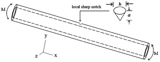
Figure 4.
Schematic diagram of the LSN tube.
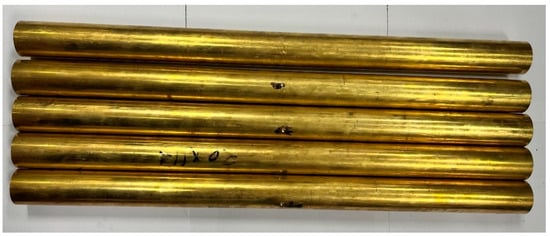
Figure 5.
Visual representation of the LSN C2700 brass circular tubes.
Since the sharp notch is local, the orientation (ϕ) of the sharp notch is expected to influence the response and local buckling of the LSN tubes. Therefore, ϕ must be taken into consideration. In Figure 6, orientations of ϕ at 0°, 30°, 60°, 90°, 120°, 150°, and 180° were examined. Since the bending moment is exerted in the z-direction, similar responses are expected to be observed for ϕ = 0° and ϕ = 180°, ϕ = 30° and ϕ = 150°, and ϕ = 60° and ϕ = 120° when subjected to cyclic bending loads. Consequently, this study focused solely on four orientations, specifically ϕ = 0°, 30°, 60°, and 90°.
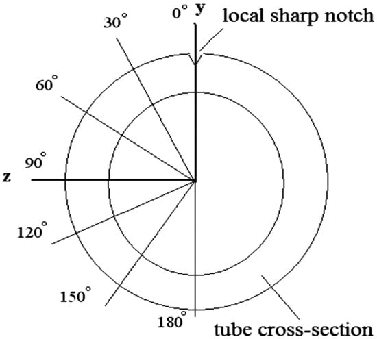
Figure 6.
Schematic diagram of the LSN tube with the notch positioned at various orientations.
2.3. Test Procedures
LSN C2700 brass circular tubes were subjected to curvature-controlled cyclic bending at a curvature rate of 0.01 m−1 s−1. The bending moment (M) was determined by using load cells in the bending machine, as depicted in Figure 1. The κ and ΔD/Do were measured by using the COMA shown in Figure 2. The number of cycles necessary to induce local buckling (Nb) was recorded, which was defined as when the M decreased by 20%.
3. Experimental Results and Discussion
3.1. M-κ Relationships
Figure 7 illustrates the M-κ relationship of the LSN C2700 brass circular tube under cyclic bending with ϕ = 0° and a = 0.2 mm. The controlled curvature ranges from −0.5 m−1 to 0.5 m−1. The experimental results indicate that in the initial stage of loading, the LSN C2700 brass circular tube undergoes elastic deformation, exhibiting a linear trend in the M-κ relationship. However, upon entering the plastic region, the M-κ relationship becomes nonlinear, with the slope of the curve gradually decreasing, indicating permanent plastic deformation of the LSN C2700 brass circular tube. When the curvature reaches the control peak value of 0.5 m−1, the bending test machine initiates reverse bending, reducing the curvature from the peak value of 0.5 m−1 to −0.5 m−1. In the initial unloading stage, the linear M-κ relationship is parallel to the linear M-κ relationship in the initial elastic range. Subsequently, the later part of the negative bending exhibits a similar behavior to the positive bending, with the slope of the curve gradually decreasing, indicating a nonlinear trend as it enters the plastic range. After completing the first cycle, the M-κ relationship graph shows a loop, and with an increase in cycles, the loops almost overlap. Due to the localized and small nature of the local sharp notches, the M-κ relationships for different values of ϕ and a are nearly identical. Therefore, only the M-κ relationship for the case of ϕ = 0° and a = 0.2 mm is presented in this study. This phenomenon aligns with the experimental findings of Lee et al. [29] on LSN SS304 circular tubes under cyclic bending loads, where stable loops remain unaffected by ϕ and a.
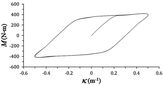
Figure 7.
M-κ relationship of the LSN C2700 brass circular tube under cyclic bending with ϕ = 0° and a = 0.2 mm.
3.2. D/Do-κ Relationships
Figure 8a–e, respectively, depict the ΔD/Do-κ relationships of LSN C2700 brass circular tubes under cyclic bending with a fixed ϕ = 0° and different a values: 0.2, 0.4, 0.6, 0.8, 1.0 mm. The controlled curvature ranges from −0.5 m−1 to 0.5 m−1. The experimental results show that regardless of deformation in the elastic or plastic range, the ΔD/Do-κ curve exhibits a nonlinear trend. When the LSN C2700 brass circular tube is loaded, ΔD/Do shows an increasing trend, reaching its peak when the curvature is 0.5 m−1. Subsequently, in the unloading phase, ΔD/Do shows a decreasing trend, and when the curvature reaches 0.0 m−1, ΔD/Do is not zero, indicating plastic deformation in the LSN C2700 brass circular tube. During the reverse loading phase, ΔD/Do shows an increasing trend again, reaching its peak when the curvature is −0.5 m−1. Then, in the reloading phase, when the curvature returns to 0.0 m−1, ΔD/Do increases slightly. Through repeated cyclic loading, the ΔD/Do-κ curve exhibits an increasing, serrated, and symmetrical trend. It is observed that as a increases, the growth of ΔD/Do also increases. This phenomenon is consistent with the experimental results of Lee et al. [29]. However, a less consistent observation is that when a is small, the ΔD/Do-κ relationships are symmetrical, but when a is large, the ΔD/Do-κ relationships are asymmetrical.
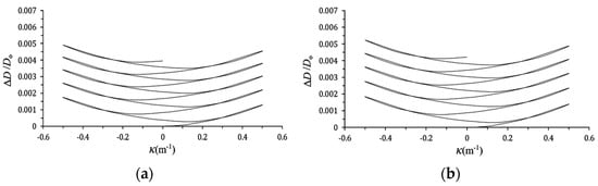
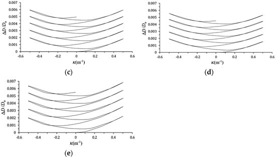
Figure 8.
ΔD/Do-κ relationships of LSN C2700 brass circular tubes under cyclic bending with a fixed ϕ = 0° and different a values: (a) 0.2, (b) 0.4, (c) 0.6, (d) 0.8, (e) 1.0 mm.
Figure 9a–d, respectively, illustrate the ΔD/Do-κ relationships of LSN C2700 brass circular tubes under cyclic bending with different ϕ values: 0°, 30°, 60°, 90° and a fixed a = 1.0 mm. It can be observed that a smaller ϕ leads to a larger ΔD/Do. This phenomenon is consistent with the experimental results of Lee et al. [29]. However, our study found that the ΔD/Do-κ curve exhibits an increasing, serrated, and symmetrical trend for any ϕ. This differs from the experimental results of Lee et al. [29], where they observed asymmetrical ΔD/Do-κ relationships for small values of ϕ but symmetrical relationships for large values of ϕ.
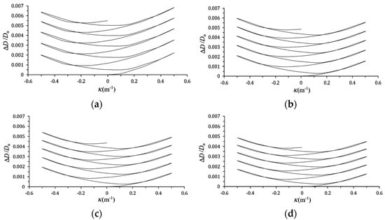
Figure 9.
ΔD/Do-κ relationships of LSN C2700 brass circular tubes under cyclic bending with different ϕ values: (a) 0°, (b) 30°, (c) 60°, (d) 90° and a fixed a = 1.0 mm.
3.3. Controlled Curvature (κc/κo)-Nb Relationships
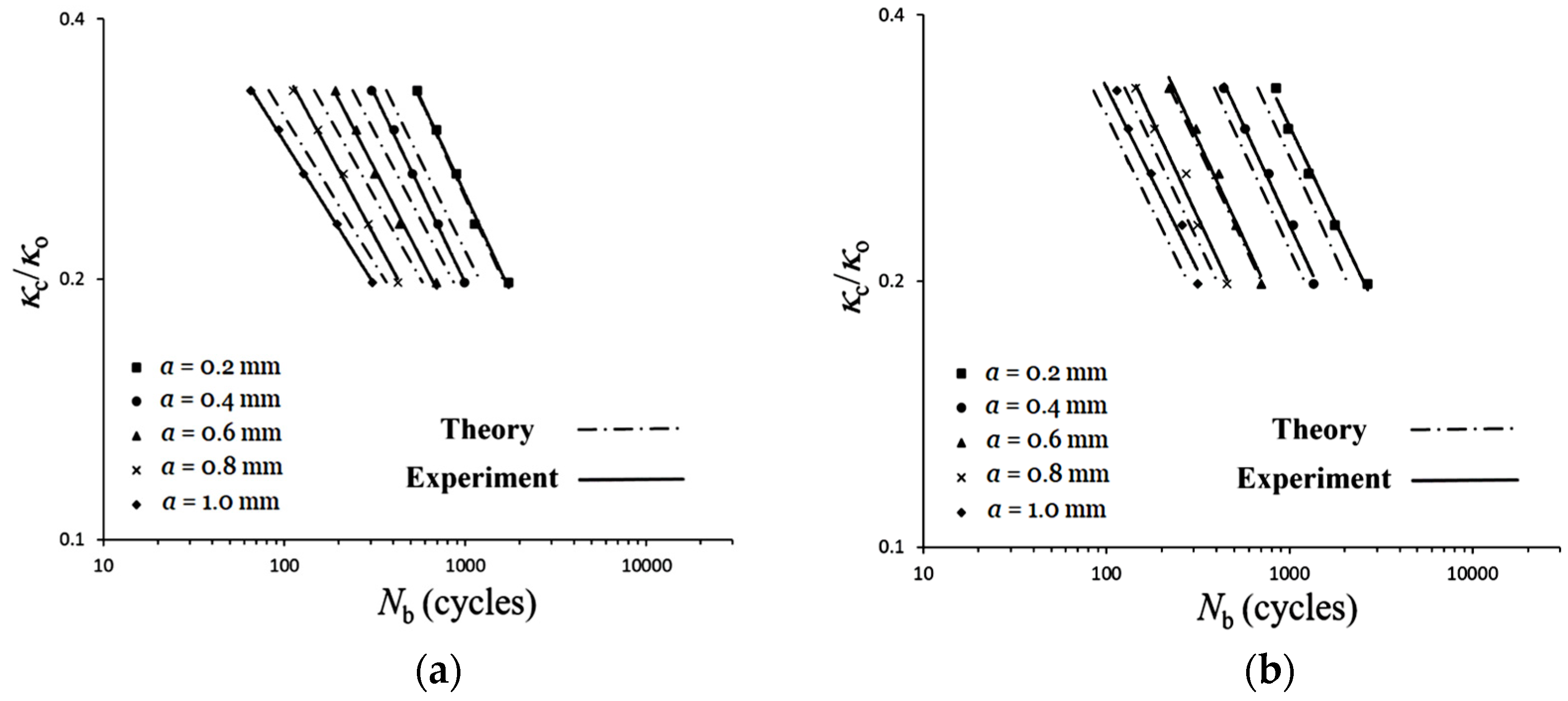
Table 1a–d present the Nb values for LSN C2700 brass circular tubes under cyclic bending with different a and κc/κo at ϕ values: 0°, 30°, 60°, and 90°. Additionally, Figure 10a–d illustrate the experimental κc/κo-Nb relationships for LSN C2700 brass circular tubes under cyclic bending with varying ϕ values: 0°, 30°, 60°, 90°, as well as different a. Here, κo is used to nondimensionalize κc, calculated as κo = t/Do2. The experimental results indicate that, for fixed values of ϕ and a, larger values of κc/κo correspond to a reduced Nb. Similarly, when ϕ and κc/κo are fixed, larger values of a result in a decreased Nb. Meanwhile, for fixed values of a and κc/κo, larger values of ϕ lead to an increased Nb. Figure 11a–d depict the same data as Figure 10a–d using double logarithmic coordinates, with straight lines representing the results of least squares fitting. This phenomenon is consistent with the experimental results of Lee et al. [29]. However, an inconsistency arises. For a certain ϕ, Lee et al. [29] showed five almost-parallel straight lines, while this study found five non-parallel straight lines. Note that for each κc/κo, two LSN C2700 brass circular tubes were tested, and there was no significant difference in the obtained Nb.

Table 1.
Nb values for LSN C2700 brass circular tubes under cyclic bending with different a and κc/κo at different ϕ.
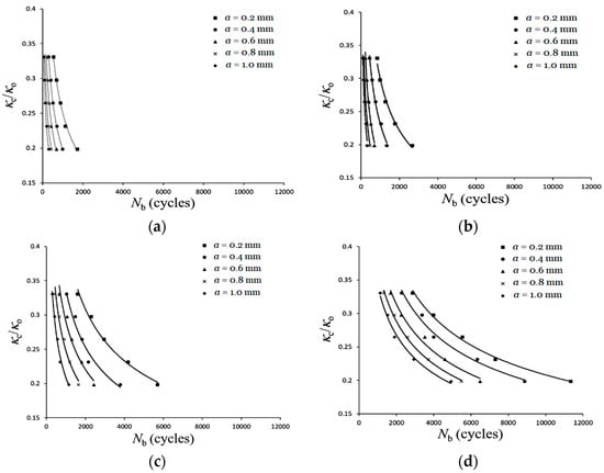
Figure 10.
Experimental κc/κo-Nb relationships for LSN C2700 brass circular tubes under cyclic bending with varying ϕ values: (a) 0°, (b) 30°, (c) 60°, (d) 90° and different a.
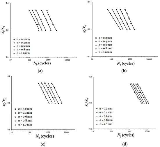
Figure 11.
Experimental κc/κo-Nb relationships for LSN C2700 brass circular tubes under cyclic bending with varying ϕ values: (a) 0°, (b) 30°, (c) 60°, (d) 90° and different a on double logarithmic coordinates.
Shaw and Kyriakides [1] proposed the following κc/κo-Nb relationship for smooth tubes under cyclic bending in 1987:
or
in which C and α are material parameters associated with the mechanical properties of the material and the geometric shape. The value of α represents the slope of the double logarithmic coordinates line relationship between κc/κo and Nb, while C indicates the corresponding value of κc/κo when Nb is 1. However, this formula cannot cover the κc/κo-Nb relationship for LSN SS304 circular tubes under cyclic bending with different ϕ and a. Therefore, Lee et al. [29] proposed that the relationship between C and a is as follows:
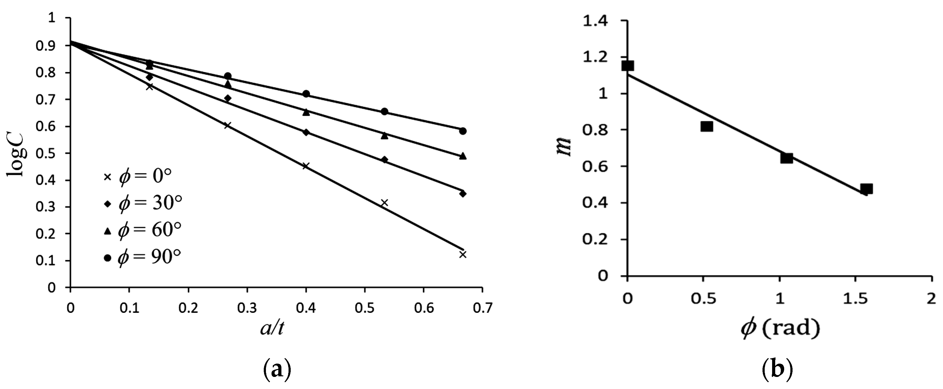
in which m and b are material parameters. The quantity m represents the slope of the logC versus a/t relationship line, while b is the logC value when a/t is 0. Through experiments, the logC versus a/t relationships for different ϕ are shown in Figure 11a. It can be observed that Equation (4) is also applicable to LSN C2700 brass circular tubes. Four lines with different slopes are shown in Figure 12a. If these lines are extended to a/t = 0, they represent the scenario without notches. The logC values at this point converge to approximately 0.91; hence, b is 0.91. In addition, the values of m are determined for ϕ = 0°, 30°, 60°, and 90°, corresponding to 1.15, 0.82, 0.64, and 0.48, respectively, as shown in Figure 12b. Through curve fitting, a linear relationship is found; thus, this study proposes:
where m1 and m2 are material parameters, and they can be derived as −0.4196 and 1.1029, respectively. However, based on the experimental results of Lee et al. [29], it was found that the relationship between m and ϕ is described by the following equation:
κc/κo = C(Nb)−α
logκc/κo = logC − αlogNb,
logC = −m(a/t) + b,
m = m1ϕ + m2, 0 ≤ ϕ ≤ π/2,
(1.37 − m)m1 = m2ϕ, 0 ≤ ϕ ≤ π/2.
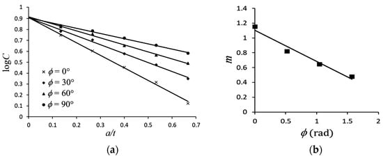
Figure 12.
(a) Relationship between logC and a/t for different ϕ, and (b) relationship between m and ϕ.
Next, this paper continues to discuss the form of α. Lee et al. [29] found that for a specific ϕ, the κc/κo-Nb relationship on double logarithmic coordinates showed five almost-parallel straight lines. Based on this observation, they proposed the form of α to be:
where a1 and a2 are material parameters. However, the κc/κo-Nb relationship on double logarithmic coordinates showed five non-parallel straight lines in this study. Therefore, this study first attempts to establish the relationship between α and a/t. From Figure 11a–d, the α-a/t relationship for different ϕ can be obtained, as shown in Figure 13a. Thus, the following proposal is made:
where β and γ are material parameters. The quantity β represents the slope of the line in the α versus a/t relationship, while γ is the value of α when a/t is 0. The values of β for ϕ = 0°, 30°, 60°, and 90° are 0.213, 0.0338, 0.036, and 0.054, respectively. The relationship between the two is depicted in Figure 13b. Based on the results of curve fitting, this study proposes:
where β1, β2, β3, and β4 are material parameters, and their values are determined as β1 = −0.1923, β2 = 06329, β3 = −0.6209, and β4 = 0.2131. As for γ values, they are found to be 0.4864, 0.4507, 0.4134, and 0.3892 for ϕ = 0°, 30°, 60°, and 90°, respectively. The relationship between the two is shown in Figure 13c. Due to its linear nature, this study proposes:
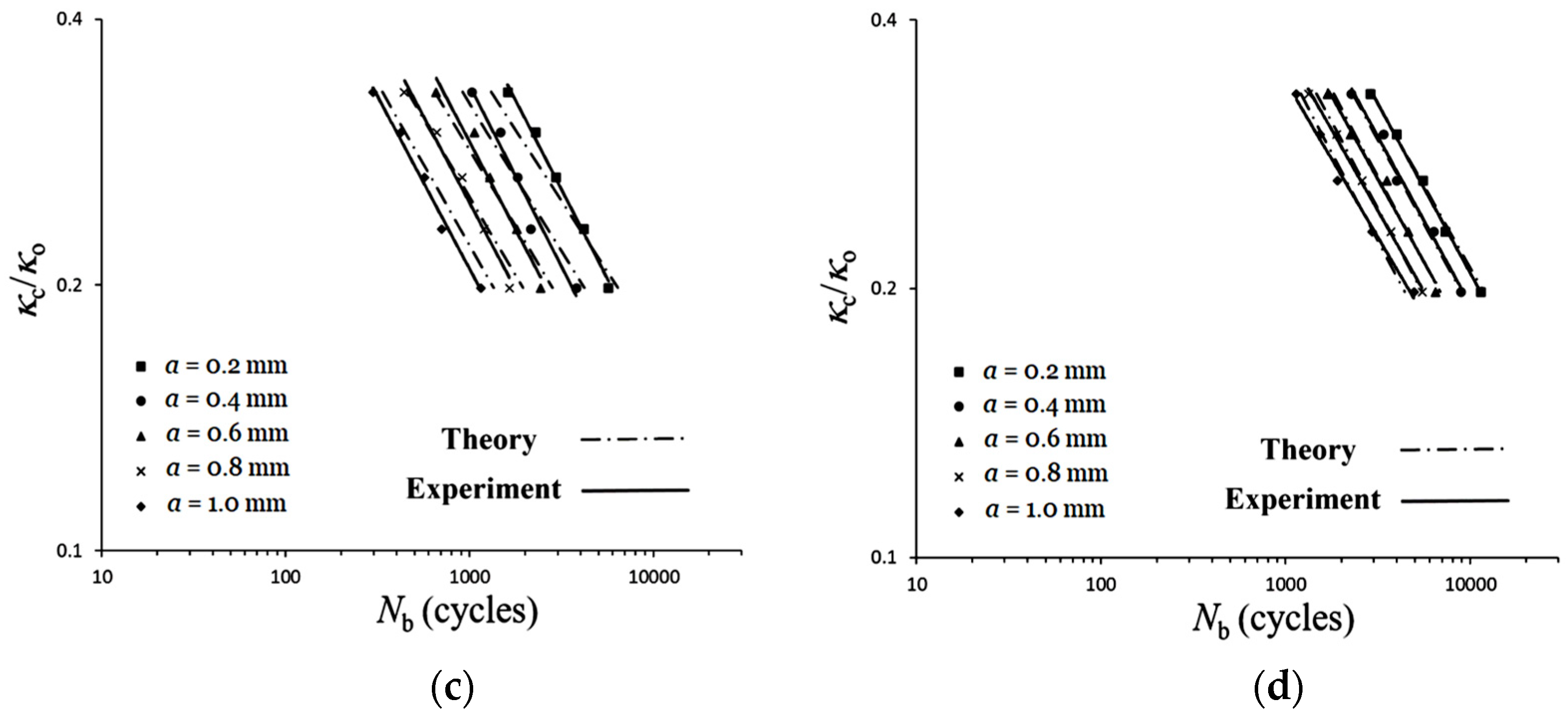
where γ1 and γ2 are material parameters, and their values are determined as γ1 = −0.0628 and γ2 = 0.4843. Figure 14a–d illustrate the experimental and theoretical κc/κo-Nb relationships for LSN C2700 brass circular tubes under cyclic bending with varying ϕ values: 0°, 30°, 60°, 90°, and different a on double logarithmic coordinates. The comparison results demonstrate that the theoretical predictions reasonably describe the experimental results.
α1/3= a1ϕ + a2, 0 ≤ ϕ ≤ π/2,
α = −β(a/t) + γ,
β = β1ϕ3 + β2ϕ2 + β3ϕ + β4, 0 ≤ ϕ ≤ π/2
γ = γ1ϕ + γ2, 0 ≤ ϕ ≤ π/2
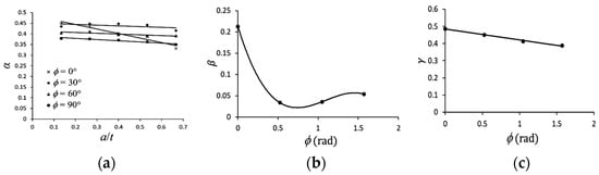
Figure 13.
(a) Relationship between α and a/t for different ϕ, (b) relationship between β and ϕ, and (c) relationship between γ and ϕ.
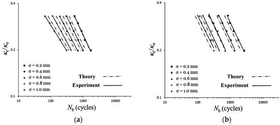
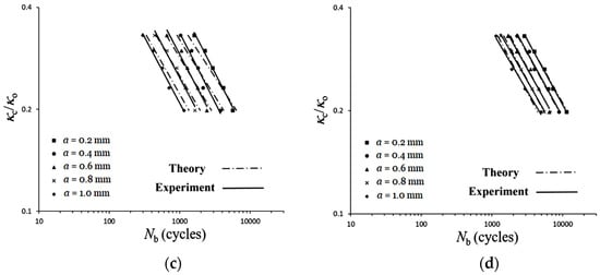
Figure 14.
Experimental and theoretical κc/κo-Nb relationships for LSN C2700 brass circular tubes under cyclic bending with varying ϕ values: (a) 0°, (b) 30°, (c) 60°, (d) 90° and different a on double logarithmic coordinates.
4. Conclusions
This study primarily investigates the response and local buckling of LSN C2700 brass circular tubes at different ϕ of 0°, 30°, 60°, and 90° and different a of 0.2, 0.4, 0.6, 0.8, and 1.0 mm under cyclic bending loads. The behavior of LSN SS304 circular tubes with different ϕ and a under cyclic bending tested by Lee et al. [29] is compared. Based on tested, analyzed, and compared data, the following conclusions can be drawn:
- (1)
- When local buckling has not yet occurred, it is observed from the experimental M-κ relationships that as κ increases, M also increases. Under cyclic bending loads, the M-κ relationship exhibits a stable loop until eventual local buckling failure. Additionally, results indicate that for different values of ϕ and a, the M-κ relationships show similar loops. This phenomenon is consistent with the experimental results reported by Lee et al. [29].
- (2)
- When local buckling has not yet occurred, it is observed from the experimental ΔD/Do-κ relationships that higher κ leads to increased ΔD/Do. Larger a or smaller ϕ values correspond to increased ΔD/Do. This phenomenon is consistent with the experimental results of Lee et al. [29]. In addition, under cyclic bending loads, the ΔD/Do-κ relationships exhibit a ratcheting, symmetrical, and growing trend. A less consistent observation with the experimental results of Lee et al. [29] is that when a is small, the ΔD/Do-κ relationships are symmetrical, but when a is large, the ΔD/Do-κ relationships are asymmetrical.
- (3)
- The experimental κc/κo-Nb relationships reveal that, when ϕ and a are fixed, larger κc/κo leads to fewer Nb. Fixing ϕ and κc/κo, larger a results in fewer Nb. Conversely, when fixing a and κc/κo, larger ϕ leads to more Nb. When ϕ is fixed, the relationships of κc/κo-Nb for five different a on double logarithmic coordinates exhibit nearly straight lines. This phenomenon is consistent with the experimental results of Lee et al. [29]. However, for a certain ϕ, they show almost-parallel lines, while we found non-parallel lines.
- (4)
- This study adopts the formula (Equation (3)) proposed by Kyriakides and Shaw [1] to describe the κc/κo-Nb relationships. The formulation of the material parameter C in Equation (4) proposed by Lee et al. [29] was used in this study. However, the material parameter m (Equation (5)) was proposed based on the experimental data. Additionally, a new equation for the material parameter α is proposed (Equation (8)), where material parameters β and γ are derived from Equations (9) and (10), respectively. Note that Equations (5), (9) and (10) are restricted to use between 0° and 90°. Finally, the theoretical Equations (Equations (3)–(5) and (7)–(10)) are employed to describe the κc/κo-Nb relationships for LSN C2700 brass circular tubes under cyclic bending with varying ϕ values: 0°, 30°, 60°, 90°, and different a (dashed lines in Figure 14a–d), and the results of experimental and theoretical analyses are reasonably consistent.
Author Contributions
Conceptualization, W.-F.P. and Y.-A.C.; methodology, W.-F.P.; software, Y.-A.C.; validation, W.-F.P. and Y.-A.C.; formal analysis, W.-F.P. and Y.-A.C.; investigation, Y.-A.C.; resources, W.-F.P.; data curation, Y.-A.C.; writing—original draft preparation, W.-F.P.; writing—review and editing, W.-F.P. All authors have read and agreed to the published version of the manuscript.
Funding
This research was supported by the National Science and Technology Council Funds (NSTC 112–221–E–006–174).
Data Availability Statement
The original contributions presented in the study are included in the article, further inquiries can be directed to the corresponding author.
Acknowledgments
The research was conducted with the generous support of the National Science and Technology Council. We extend our heartfelt gratitude for their invaluable assistance.
Conflicts of Interest
The authors declare no conflicts of interest.
References
- Kyriakides, S.; Shaw, P.K. Inelastic buckling of tubes under cyclic bending. J. Press. Vessel Technol. 1987, 109, 169–178. [Google Scholar] [CrossRef]
- Corona, E.; Kyriakides, S. An experimental investigation of the degradation and buckling of circular tubes under cyclic bending and external pressure. Thin-Walled Struct. 1991, 12, 229–263. [Google Scholar] [CrossRef]
- Corona, E.; Kyriakides, S. Asymmetric collapse modes of pipes under combined bending and pressure. Int. J. Solids Struct. 2000, 24, 505–535. [Google Scholar] [CrossRef]
- Corona, E.; Lee, L.H.; Kyriakides, S. Yield anisotropic effects on buckling of circular tubes under bending. Int. J. Solids Struct. 2006, 43, 7099–7118. [Google Scholar] [CrossRef]
- Limam, A.; Lee, L.H.; Corana, E. Inelastic wrinkling and collapse of tubes under combined bending and internal pressure. Int. J. Mech. Sci. 2010, 52, 37–47. [Google Scholar] [CrossRef]
- Limam, A.; Lee, L.H.; Corona, E.; Kyriakides, S. On the collapse of dented tubes under combined bending and internal pressure. Int. J. Solids Struct. 2012, 55, 1–12. [Google Scholar] [CrossRef]
- Bechle, N.J.; Kyriakides, S. Localization of NiTi tubes under bending. Int. J. Solids Struct. 2014, 51, 967–980. [Google Scholar] [CrossRef]
- Jiang, D.; Kyriakides, S.; Bechle, N.J.; Landis, C.M. Bending of pseudoelastic NiTi tubes. Int. J. Solids Struct. 2017, 124, 192–214. [Google Scholar] [CrossRef]
- Kazinakis, K.; Kyriakides, S.; Jiang, D.; Bechle, N.J.; Landis, C.M. Buckling and collapse of pseudoelastic NiTi tubes under bending. Int. J. Solids Struct. 2021, 221, 2–17. [Google Scholar] [CrossRef]
- Yuan, W.; Mirmiran, A. Buckling analysis of concrete-filled FRP tubes. Int. J. Struct. Stab. Dyn. 2001, 1, 367–383. [Google Scholar] [CrossRef]
- Elchalakani, M.; Zhao, X.L.; Grzebieta, R.H. Plastic mechanism analysis of circular tubes under pure bending. Int. J. Mech. Sci. 2002, 44, 1117–1143. [Google Scholar] [CrossRef]
- Elchalakani, M.; Zhao, X.L.; Grzebieta, R.H. Variable amplitude cyclic pure bending tests to determine fully ductile section slenderness limits for cold-formed CHS. Eng. Struct. 2006, 28, 1223–1235. [Google Scholar] [CrossRef]
- Zhi, X.D.; Fan, F.; Shen, S.Z. Failure mechanism of single-layer cylindrical reticulated shells under earthquake motion. Int. J. Struct. Stab. Dyn. 2012, 12, 233–249. [Google Scholar] [CrossRef]
- Yazdani, H.; Nayebi, A. Continuum damage mechanics analysis of thin-walled tube under cyclic bending and internal constant pressure. Int. J. Appl. Mech. 2013, 5, 1350038. [Google Scholar] [CrossRef]
- Guo, L.; Yang, S.; Jiao, H. Behavior of thin-walled circular hollow section tubes subjected to bending. Thin-Walled Struct. 2013, 73, 281–289. [Google Scholar] [CrossRef]
- Elchalakani, M.; Karrech, A.; Hassanein, M.F.; Yang, B. Plastic and yield slenderness limits for circular concrete filled tubes subjected to static pure bending. Thin-Walled Struct. 2016, 109, 50–64. [Google Scholar] [CrossRef]
- Shamass, R.; Alfano, G.; Guarracino, F. On elastoplastic buckling analysis of cylinders under nonproportional loading by differential quadrature method. Int. J. Struct. Stab. Dyn. 2017, 17, 1750072. [Google Scholar] [CrossRef]
- Chegeni, B.; Jayasuriya, S.; Das, S. Effect of corrosion on thin-walled pipes under combined internal pressure and bending. Thin-Walled Struct. 2019, 143, 106218. [Google Scholar] [CrossRef]
- Jin, S.; Cheng, P.; Saneian, M.; Yong, B. Mechanical behavior of thin tubes under combined axial compression and bending. Thin-Walled Struct. 2021, 159, 107255. [Google Scholar] [CrossRef]
- Silveira1, T.; Pinto, V.T.; Neufeld, J.P.S.; Pavlovic, A.; Rocha, L.A.O.; Santos, E.D.; Isoldi, L.A. Applicability evidence of constructal design in structural engineering: Case study of biaxial elasto-plastic buckling of square steel plates with elliptical cutout. J. Appl. Comp. Mech. 2021, 7, 922–934. [Google Scholar]
- Montes, D.; Janer, M.; Caminati, R.; Plantà, X. Experimental study on the bending of a polyamide tube using high-power ultrasound. J. Adv. Man. Sys. 2021, 20, 191–204. [Google Scholar] [CrossRef]
- Shi, J.; Zhong, S.; Nie, X.; Shi, J.; Zheng, J. Study on steel wire reinforced thermoplastic pipes under combined internal pressure and bending moment at various temperatures. Thin-Walled Struct. 2022, 169, 108381. [Google Scholar] [CrossRef]
- Chen, J.; Zhu, Y.; Wang, F.; Feng, B. Experimental and analytical study of hollow section concrete-filled GFRP tubes in bending. Thin-Walled Struct. 2022, 177, 109297. [Google Scholar] [CrossRef]
- Lavayen-Farfan, D.; Butenegro-Garcia, J.A.; Boada, M.J.L.; Martinez-Casanova, M.A.; Rodriguez-Hernandez, J.A. Theoretical and experimental study of the bending collapse of partially reinforced CFRP–Steel square tubes. Thin-Walled Struct. 2022, 177, 109457. [Google Scholar] [CrossRef]
- He, Z.R.; Li, G.J.; Yang, J.C.; Guo, X.Z.; Duan, X.Y.; Guo, W.; Liu, X.; Deng, Y.Y.; Cheng, C. Insight into the deformation transition effect in free bending of tubes. Mater. Lett. 2023, 348, 134673. [Google Scholar] [CrossRef]
- Wang, J.; Li, J.R.; Li, H.; Lv, L.Y. Behaviour of square concrete-filled steel tubes reinforced with internal latticed steel angles under bending. Structures 2023, 48, 1436–1454. [Google Scholar] [CrossRef]
- Wu, Z.; Li, J.; Shi, L.; Chen, X. Effect of stacking configuration on the mechanical property and damage behavior of braided composite tube under three-point bending. Thin-Walled Struct. 2023, 187, 110762. [Google Scholar] [CrossRef]
- Duda, S.; Smolnicki, M.; Stabla, P.; Zielonka, P.; Osiecki, T.; Gao, C.; Lesiuk, G. Experimental characterization and modeling of cylindrical CFRP structures under quasi-static multiaxial loading conditions. Thin-Walled Struct. 2024, 195, 111364. [Google Scholar] [CrossRef]
- Lee, K.L.; Chang, K.H.; Pan, W.F. Effects of notch depth and direction on stability of local sharp-notched circular tubes subjected to cyclic bending. Int. J. Struct. Stab. Dyn. 2018, 18, 1850099. [Google Scholar] [CrossRef]
- Pan, W.F.; Wang, T.R.; Hsu, C.M. A curvature-ovalization measurement apparatus for circular tubes under cyclic bending. Exp. Mech. 1998, 38, 99–102. [Google Scholar] [CrossRef]

Disclaimer/Publisher’s Note: The statements, opinions and data contained in all publications are solely those of the individual author(s) and contributor(s) and not of MDPI and/or the editor(s). MDPI and/or the editor(s) disclaim responsibility for any injury to people or property resulting from any ideas, methods, instructions or products referred to in the content. |
© 2024 by the authors. Licensee MDPI, Basel, Switzerland. This article is an open access article distributed under the terms and conditions of the Creative Commons Attribution (CC BY) license (https://creativecommons.org/licenses/by/4.0/).