Article

Effect of Printing Orientation on the Mechanical Properties of 3D-Printed Cu–10Sn Alloys by Laser Powder Bed Fusion Technology

1
School of Materials Science and Engineering, Jiangsu University of Science and Technology, Zhenjiang 212100, China
2
College of Materials Science and Engineering, Beijing University of Technology, Beijing 100124, China
3
Material Science and Technology of Metals, Admiral Makarov National University of Shipbuilding Institute, 54025 Nikolaev, Ukraine
*
Author to whom correspondence should be addressed.
Metals 2024, 14(6), 660; https://doi.org/10.3390/met14060660
Submission received: 18 April 2024 / Revised: 24 May 2024 / Accepted: 28 May 2024 / Published: 1 June 2024
(This article belongs to the Topic Laser Processing of Metallic Materials)

Abstract

:
This article focuses on investigating the effect of printing direction on the mechanical properties of Cu–10Sn alloys prepared by laser powder bed fusion (LPBF) technology. Specimens with different forming angles (0°, 15°, 30°, 45°, 60°, 75°, and 90°) were fabricated using LPBF technology, and their mechanical properties were systematically tested. During the testing process, we used an Instron 5985 electronic universal material testing machine to accurately evaluate the mechanical properties of the material at a constant strain rate of 10−3/s. The experimental results showed that the mechanical properties of the specimens were the best when the test direction was perpendicular to the growth direction (i.e., the 0° direction). As the angle between the test direction and the growth direction increased, the mechanical properties of the material exhibited a trend of first decreasing, then increasing, and then decreasing again, which was consistent with the direction of the microtexture of the specimens. The root cause of this trend lies in the significant change in the stress direction borne by the columnar crystals under different load directions. Specifically, as the load direction gradually transitions from being parallel to the columnar crystals to perpendicular to them, the stress direction of the columnar crystals also shifts from the radial direction to the axial direction. Due to the differences in the number and strength of grain boundaries in different stress directions, this directly leads to changes in mechanical properties. In particular, when the specimen is loaded in the radial direction of the columnar crystals, the grain boundary density is higher, and these grain boundaries provide greater resistance during dislocation migration, thus significantly hindering tensile deformation and enabling the material to exhibit superior tensile properties. Among all the tested angles, the laser powder bed fusion specimen with a forming angle of 0° exhibited the best mechanical properties, with a tensile strength of 723 MPa, a yield strength of 386 MPa, and an elongation of 33%. In contrast, the specimen with a forming angle of 90° performed the worst in terms of tensile properties. These findings provide important insights for us to deeply understand the mechanical properties of Cu–10Sn alloys prepared by LPBF.

1. Introduction

Cu–Sn alloys possess numerous advantageous properties, including remarkable mechanical strength, superior wear resistance, high corrosion resistance, elasticity, electrical conductivity, and excellent weldability. These properties have rendered them indispensable in military and civilian electronics, industrial electrical equipment, and cutting-edge network communication technologies [1,2,3]. Generally speaking, tin bronzes with low tin content (less than 5%) are extensively utilized in the electrical and electronics industry for plastic processing applications, such as in sensitive components in pressure gauges, electrical connectors, and high-precision springs [4,5]. As the tin content increases, the mechanical properties of tin bronzes are enhanced accordingly. A tin content of approximately 10% is considered to be the optimal composition for achieving superior mechanical properties, balancing strength and ductility [6]. When the tin content exceeds 10%, high tin bronzes exhibit exceptional mechanical properties, wear resistance, and corrosion resistance, making them ideal for applications in the marine and mechanical industries, such as in ship components and bearings [7,8]. However, high-tin bronzes are prone to brittle δ-phase formation and encounter difficulties in plastic deformation, and thus their primary manufacturing process is casting [3]. Consequently, the Cu–10Sn alloy, with a tin content of 10%, was selected as the focus of this study.
Owing to the escalating demands for geometrically intricate structures, LPBF technology has gained widespread adoption due to its proficiency in rapidly fabricating complex and precise components [9]. LPBF, a layer-by-layer additive manufacturing technique, offers the unique advantage of shaping parts with intricate internal geometries, which is a challenge in traditional subtractive manufacturing methods. Traditional methods are inherently limited in processing components with enclosed cavities or highly intricate internal microstructures. However, with LPBF, microstructured parts can be precisely crafted, and under the condition of ensuring part accuracy, walls or holes with a minimal thickness of 0.1 mm can be achieved. Furthermore, the LPBF method enables the fabrication of components with internal structures that are unattainable through traditional means, significantly reducing the weight of the parts while still fulfilling the performance requirements [10,11,12]. Conversely, tin bronze parts produced via the conventional casting process are prone to numerous defects, including shrinkage, micro-cracking, and severe segregation [13]. Consequently, there is a pressing need to develop novel technological tools to enhance the mechanical properties and mitigate defects in tin bronze, aiming to broaden its industrial applicability. Unlike conventional preparation methods, LPBF, an additive manufacturing technique utilizing a powder bed, enables the fabrication of near-full-density metal components. This process employs a computer-controlled laser to selectively melt metal powder layer by layer on a build platform, thereby permitting the production of parts with virtually any geometry and complexity [14,15,16]. LPBF technology boasts a range of advantages compared to traditional manufacturing methods. Firstly, the LPBF process can directly manufacture structures and highly complex parts that are challenging or even impossible to process with conventional techniques. Secondly, the performance of the parts obtained is comparable to those fabricated by forging. Thirdly, LPBF manufacturing does not necessitate expensive tools or auxiliary machining equipment, significantly reducing costs and processing time [17]. Moreover, LPBF technology not only facilitates the manufacture of parts with intricate shapes but also introduces the possibility of sub-stable phases and microstructures. During the forming process, LPBF is capable of generating micron-sized melt pools, accompanied by extremely high cooling rates.
Numerous studies have demonstrated the unique processing parameters inherent in LPBF, which influence the microstructural characteristics and resulting mechanical properties [18,19,20]. Of particular importance is the high cooling rate, up to 108 K/s [21]. Due to this high cooling rate, there is a high chance of forming sub-stable phases or finely solidified substructures. For example, in Cu–Sn, the LPBF microstructure obtained is that of fine columnar crystals [22]. During the LPBF forming process, due to the extreme temperature gradient in the melt pool and remelting and cooling between neighboring melt pools, the grains grow outwards and form columnar crystals. Cu–Sn alloys show significant epitaxial growth [23]. When the Sn content is increased to 15 wt.%, the columnar grains in the alloy can be epitaxially grown through one to two melt pools and the columnar grains grow along the center of the melt pool. Most of the columnar grains in the copper alloy grow along multiple melt cell trajectories parallel to the growth direction. This further suggests that the formation and evolution of the microstructure in Cu–Sn alloys is mainly controlled by the Sn content and the solidification of the deposited layers during the forming process. In addition, the mechanical properties of LPBF-formed Cu–Sn alloy specimens are better than those of cast specimens. This is due to the large number of fine grains produced by the extremely fast melting and cooling rate during the LPBF forming process. At the same time, there is a large number of dislocations entangled within the grains. The high density of dislocations and fine grain reinforcement greatly improve the mechanical properties of the LPBF-formed parts. Almost all metal alloys currently formed in LPBF exhibit epitaxial growth from the previous build layer, resulting in grain elongation in the build direction. Titanium alloys in particular exhibit very large columnar crystals in LPBF Ti–6Al–4V [24,25]. However, there is no report on the effect of forming angle of LPBF on the mechanical properties of its microstructure and tensile parts. The scanning strategy has a significant impact on the quality and performance of LPBF-formed parts. Although significant progress has been made in recent years through extensive research into the materials, processes, microstructures, and properties of LPBF forming, the process has had to face one major drawback, namely, poor surface quality. Good surface quality is particularly critical to prevent premature failure due to surface cracking, so parts are generally machined in a post-treatment process to improve the surface quality of the part, but this undoubtedly increases part cycle time and manufacturing costs. As such, this paper focuses on the correlation between different forming angles and the mechanical properties of its LPBF-formed parts.
This study deeply explored the influence of processing parameters such as laser power, scanning speed, and hatch space on the density of LPBF Cu–10Sn bronze parts through the comprehensive application of experimental methods, especially response surface methodology (RSM) and analysis of variance (ANOVA) techniques. We aim to manufacture LPBF Cu–10Sn bronze parts with optimal density through the optimization of these parameters. This method provides a scientific and efficient approach to the optimization of the LPBF process, echoing previous studies [23,26]. After successfully manufacturing nearly fully dense LPBF Cu–10Sn specimens, we further explored the evolution mechanism of microstructure and mechanical properties in different forming directions. This step aims to deeply reveal the intrinsic relationship between microstructure and mechanical properties, providing strong support for our comprehensive understanding of alloy properties.

2. Materials and Methods
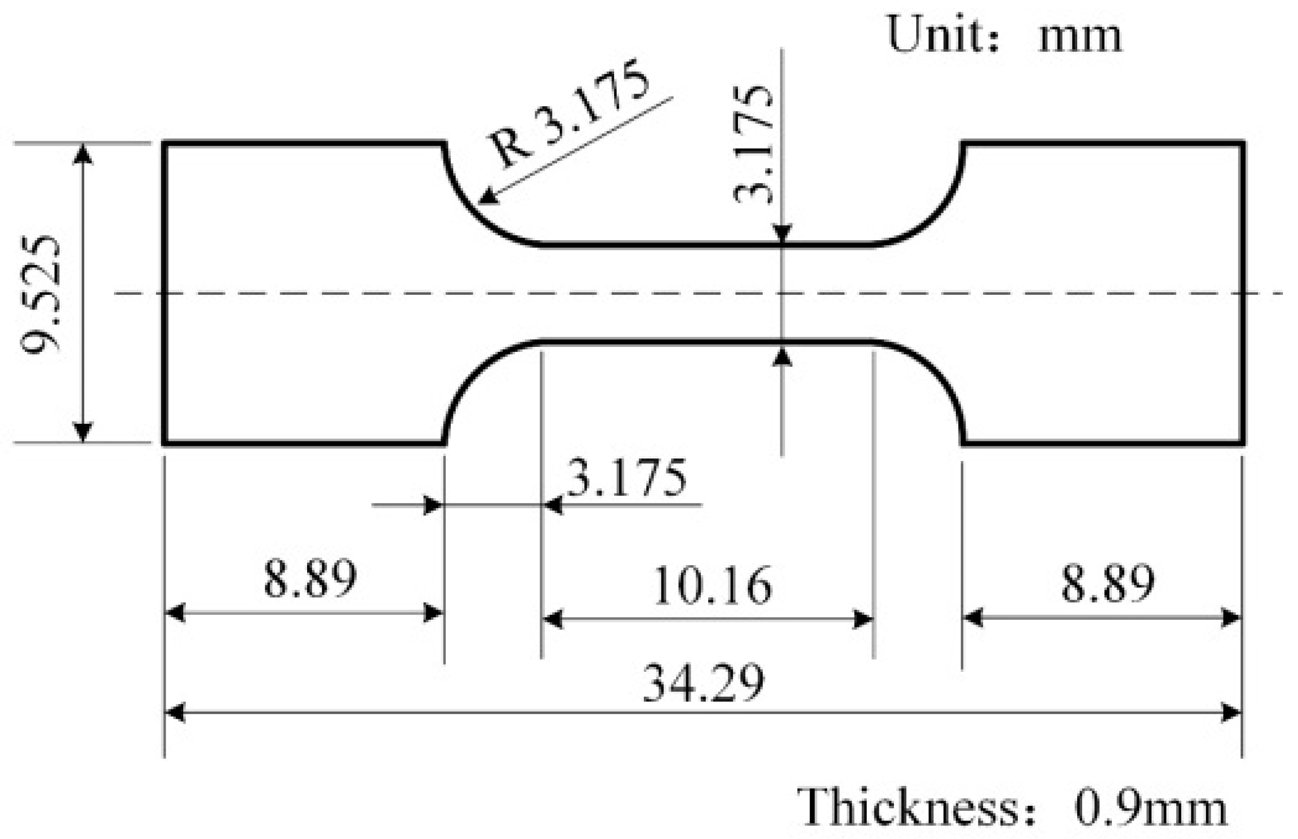
2.1. Materials

In this paper, the Cu–10Sn alloy powder required for LPBF forming was prepared using the inert gas atomization method. The raw powder was sieved with a special sieve to get the powder suitable for the LPBF process, and the particle size was concentrated in the range of 20–80 μm. The higher sphericity improved the fluidity of powder, promoted the uniformity of powder spreading, reduced the distribution of defects, and improved the quality of specimen forming. The fluidity of the powder was 23.04 s/50 g and the bulk density was 4.3818 g/mL measured by a Hall flowmeter. In the LPBF forming process, the higher bulk density of the powder resulted in a thicker powder layer thickness, and the melt pool could absorb sufficient powder to facilitate specimen forming. The oxygen content of the powder was measured to be 0.138% using a G8 Galileo ON/H analyzer (Bruker Corporation, Billerica, MA, USA). A lower oxygen content increased the wettability of the liquid melt pool, reduced the spheroidization during printing, and reduced the generation of pores during LPBF forming, improving the LPBF forming quality of the printed specimens.

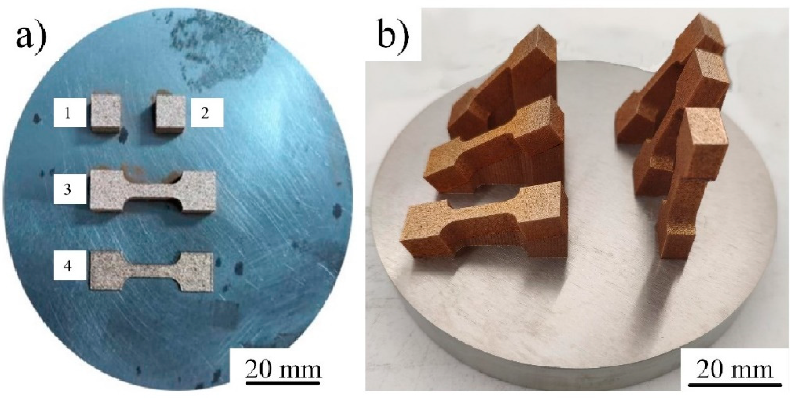
2.2. LPBF Process and Machine

In this experiment, the EOS M100 forming equipment was used for LPBF forming test, which mainly contained the computer control device, Yb-fiber laser, automatic powder dropping and scraping device with maximum laser power of 200 W, spot diameter of 40 μm, maximum scanning speed of 7 m/s, and powder laying thickness of 20–100 μm. In addition, the substrate used in this device was a circular substrate of 100 mm diameter, which uses less powder (≥2 kg) and facilitates the molding of smaller specimens. The LPBF parameters were optimized using orthogonal tests and the response surface method. The optimal process parameters were obtained as follows: laser power (LP) 120 W, scanning speed (SS) 600 mm/s, and hatch space (HS) 0.05 mm. In order to reduce the moisture content of the powder, improve its flowability and ensure the quality of LPBF-formed specimens, the powder was dried in an SG-HX300 drying oven (Shanghai Institute of Optical Precision Machinery, Chinese Academy of Sciences, Shanghai, China) for 3 h in advance. Stainless steel substrate was preheated at 80 °C. The printing chamber was filled with ≥99.999% high-purity argon gas when the chamber oxygen content was lower than 0.1% for printing.

2.3. Analysis

The mechanical properties of the materials were tested at a strain rate of 10−3/s using an Instron 5985 electronic universal material testing machine (Instron (Shanghai) Test Equipment Trading Co., Shanghai, China). The optimum process parameters (LP 120w, SS 600 mm/s, HS 0.05 mm) were used to prepare the tensile specimens, and three specimens were measured for each specimen to ensure the accuracy of the experiment. The surfaces of the specimens were ground and polished in the order of 200#, 400#, 600#, 800# and 1000# sandpaper. A schematic diagram of the tensile specimens is shown in Figure 1.
Photographic observation was carried out using a PMG3 optical microscope from Olympus (Tokyo, Japan). Surface morphology of alloy powder, tissue characteristics of LPBF-formed specimens and tensile fracture morphology analysis were characterized by scanning electron microscopy (SEM) (QUANTA-200 Scanning Electron Microscope from FEI, Hillsboro, OR, USA) using an FEI Quanta. The polished specimens were prepared in an ion polisher (Leica EM TIC 3X, Leica Mikrosysteme GmbH, Wetzlar, German) with an electron beam voltage of 4.5 kV, an electron beam gun current of 2.0 mA, an angle of 4.0°, a grinding angle of 4.0°, and a polishing time of 30 min. The degree of grain orientation, grain size, shape, and subcrystalline and lattice distortion within the formed specimen was observed using an HKL Nordlys scanning electron microscope (EBSD) (QUANTA-200 Scanning Electron Microscope from FEI, Hillsboro, OR, USA).

3. Results and Discussion

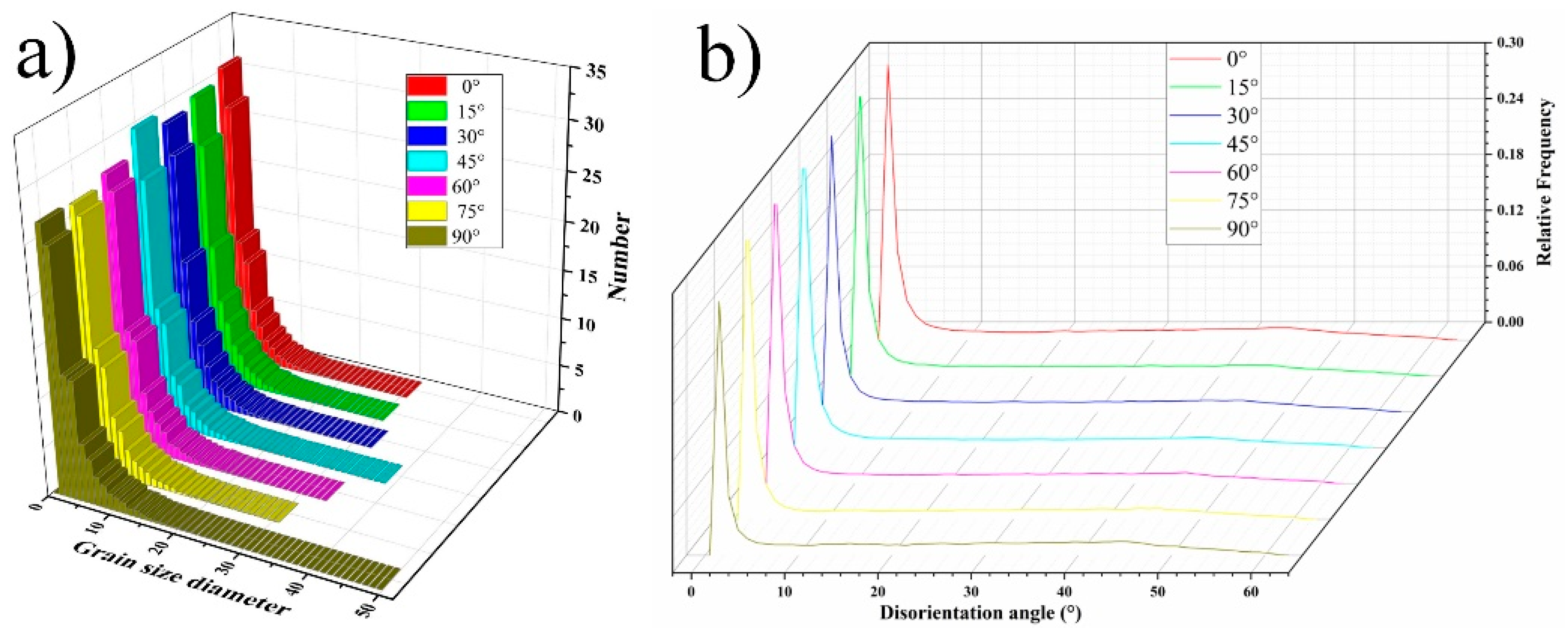
3.1. Phase and Microstructures

Figure 2 shows the XRD spectra of Cu–10Sn powder and an LPBF-built specimen. It was found that the powder and the specimen were both composed of α-Cu solid solution and Cu5.6Sn intermetallic compound. Compared with the XRD spectrum of Cu–10Sn powder, the strong diffraction peaks of LPBF-built components were in the same position, which meant that the lattice structure remains unchanged even after melting. In the detection range of XRD, there were no diffraction peaks of other phases.
Figure 3 clearly shows the 0° microstructure of the Cu–10Sn alloy specimen prepared by LPBF technology. On the horizontal plane parallel to the scanning plane, the overlapping phenomenon of the melting tracks unique to LPBF technology can be observed. These melting scanning tracks reveal the elliptical characteristics of the molten pool. In the side view, the molten pool exhibits a fan-shaped structure, with its direction perpendicular to the temperature gradient. In the vertical plane, a significant layered microstructure is observed, which is formed by the overlap of the melt channel and the boundary of the molten pool. Further observation reveals a fine arrangement in the fish-scale region. When the laser scans the surface of the specimen, the temperature gradually decreases from the center to the periphery, forming a large temperature gradient. Under such conditions, the microstructure grows along the direction of the temperature gradient, forming columnar grains. Under the layer-by-layer action of the laser, a unique fish-scale laser action zone is eventually formed. Each columnar grain has a regular geometric size in the crack region, with a width of about 10 μm and a length of up to 40 μm. Their growth direction is consistent with the temperature gradient, which is a typical grain morphology in LPBF technology. These columnar grains are usually formed by epitaxial growth, resulting from the combined effect of the remelting of the previously deposited layer and the significant temperature gradient between the deposited layers. During the LPBF formation process, the temperature gradient at the bottom of the molten pool is particularly significant. The heat flow diffuses downward along the deposited layer from the bottom of the molten pool, enabling the columnar crystals to grow epitaxially along the direction opposite to the heat dissipation direction during solidification. Additionally, the liquid composition in the molten pool is consistent with the alloy composition of the deposited layer substrate, ensuring good wettability between adjacent layers. Therefore, there is no nucleation barrier between layers, and the columnar crystals can continue to grow epitaxially along the direction of the previous layer after remelting. It is worth noting that during the LPBF process, the columnar grains growing along the build direction are significantly influenced by the direction of heat conduction. This unique growth mechanism enables the Cu–10Sn alloy to exhibit excellent properties in its microstructure [27,28,29].
The columnar crystals form on the melt pool layer and grow epitaxially along the stacking direction. It was also observed that although the columnar crystals grow along the stacking direction, the growth path was more tortuous and not exactly parallel to the stacking direction, which may be caused by the instability of the melt pool during the processing. The hole defects observed in the formed specimens were small, with a diameter of about 7 μm. During the deposition process, when the selected process parameters were not suitable or when the forming process parameters fluctuated widely causing instability of the melt pool, it was possible to form holes, interlayer unfused inclusions, porosity, and even cracks in the formed parts. For LPBF processes, it was difficult to produce fully dense formed parts, and some porosity and interlayer unfused defects would inevitably arise. The presence of these defects could seriously affect the fatigue and creep life of the material, and hot isostatic pressing was usually used to eliminate these defects and thus improve the mechanical properties of the formed part [30]. It can be seen in Figure 3 that the LPBF-formed specimens have good densities with very few pores.
Figure 4 shows the macroscopic morphology of the tensile test specimens formed by LPBF at different angles. Two cubic styles, no. 1 and no. 2, were used to analyze microstructure, XRD and densification. Specimens 3 and 4 were used to test the tensile properties of different layer thicknesses. The thickness of specimen 3 is 10 mm and that of specimen 4 is 1.5 mm. Tensile parts with different angles of 0°, 15°, 30°, 45°, 60°, 75° and 90° were prepared, and then the effect of forming angle on their microstructure and properties was analyzed.
Figure 5 clearly shows the microstructure of the LPBF specimens under different angles. We noticed that as the LPBF forming angle changes, the growth direction of the molten pool also exhibits corresponding adjustments. More remarkably, upon precise measurement, the angle between the growth direction of the molten pool and the LPBF forming direction is almost identical to the theoretical design value, fully demonstrating the precision and reliability of the technology. From a microscopic perspective, the morphology of the molten pool clearly exhibits typical LPBF technology characteristics. In Figure 5, black dotted lines and red dotted lines are marked as important reference lines. Red dotted lines indicate the forming direction of the specimen, while black dotted lines represent the inclined angle direction during design. Deep into each molten pool, we can observe that columnar crystals are distributed in multiple deposition layers, showing a tendency of epitaxial growth along the stacking direction. This discovery provides us with a valuable microscopic perspective for understanding the LPBF forming process.
To accurately reveal the texture direction distribution characteristics in the microstructure of the alloy, we conducted a series of EBSD experiments on the specimen and obtained serial results shown in Figure 6. Figure 6 shows the IPF images of the side surface (parallel to the forming direction) under different forming angles (0°, 15°, 30°, 45°, 60°, 75°, and 90°), where YD represents the forming direction and XD represents the scanning direction. In these images, the color changes intuitively reflect the diversity of grain orientations, while similar or identical colors map the consistency of grain orientations. Through the IPF image analysis of EBSD, we clearly observed the significant epitaxial grain growth phenomenon in the microstructure of Cu–10Sn specimens prepared by the LPBF process. This epitaxial growth phenomenon is mainly influenced by the heat flow direction, as the change in heat flow direction directly leads to a variation in temperature gradient, thus affecting the direction and intensity of epitaxial growth. Specifically, epitaxial growth mainly occurs in the interlayer regions along the height direction, which is closely related to the scanning strategy we chose. It is particularly noteworthy that a large number of fine grains are found in the marginal region of the molten pool. This phenomenon is attributed to the unique turbulent heat flow environment at the edge of the molten pool, where a large number of nucleated grains reduce their size in competition with each other, and only a few grains can maintain the trend of epitaxial growth. This finding is consistent with the preferential growth law of traditional face-centered crystals, further confirming the accuracy and reliability of our experimental results.
In order to determine the grain size within the alloy and the direction between adjacent grains more visually, the grain size data and grain boundary direction within the LPBF-formed alloy specimen were further analyzed using EBSD, as shown in the grain size distribution and grain boundary direction plots in Figure 7. As shown in Figure 7a, the grain size was mainly distributed between 1.5 and 5.5 μm, and the average grain size was 4.8 μm, which was small. When alloys were prepared using LPBF, they experienced extremely fast cooling rates, resulting in a high nucleation momentum that did not fully mature. The statistical graph of grain boundary direction in Figure 7b shows that there is a clear peak in the grain boundary direction on the angle of 1.5°, which has certain meritocratic direction.

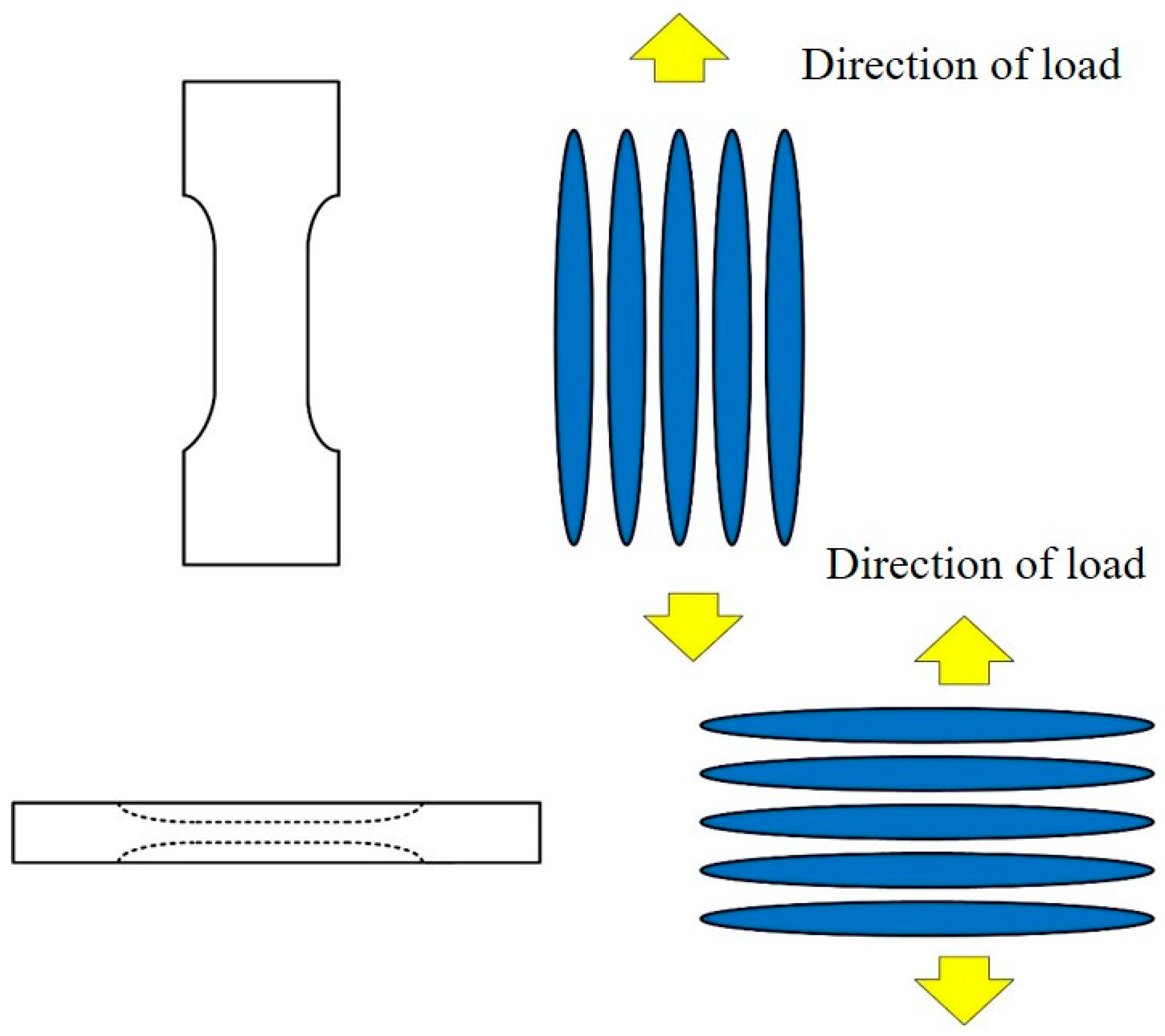
3.2. Mechanical Performance

After conducting a detailed microstructural analysis of the LPBF-formed alloy specimens, we observed a clear growth pattern of columnar grains extending along the build direction. Figure 8 not only indicates the sampling positions for tensile testing but also vividly depicts how the loading force interacts with the columnar grains during tensile testing. Notably, changes in the loading direction are directly associated with corresponding adjustments in the stress orientation of the columnar grains. Specifically, as the loading direction gradually transitions from being aligned with the columnar grains to perpendicular to them, the stress direction of the columnar grains undergoes a significant shift from radial to axial. Similarly, when the loading force is initially applied along the direction of the columnar grains and then gradually shifted to a direction perpendicular to them, the stress orientation of the grains also undergoes a similar transition from radial to axial. These significant differences in stress orientation have a profound impact on the number and strength of grain boundaries, thereby profoundly altering the mechanical properties of the alloy. To comprehensively and accurately assess the specific impact of these changes on alloy performance, we carefully selected tensile specimens at multiple different angles for tensile performance testing. This approach aimed to deeply reveal the intrinsic relationship between the loading direction and the stress orientation of the columnar grains, as well as their specific impact on the alloy’s performance.
Tensile experiments were first carried out on LPBF-formed parts with 0° angle. Due to the characteristics of LPBF formation by melting and solidifying the powder layer by layer, different layer thicknesses of the formed parts were firstly selected for tensile experiments. The stress–strain curves of the experimental results are shown in Figure 9 (LPBF-built-1 is the tensile part cut at forming 1.5 mm, and LPBF-built-2 is the tensile part cut at forming 5.5 mm), and it can be seen that the two curves almost coincide. The corresponding yield strength, tensile strength and elongation data are given in Table 1. The layer thickness of the tensile specimen is 10 mm. LPBF-built-1 is the tensile part cut at forming 1.5 mm, and LPBF-built-2 is the tensile part cut at forming 5.5 mm. From the results, it can be seen that the results of tensile experiments on specimens selected with different layer thicknesses are almost the same, indicating that there is no effect of different layer thicknesses in the sampling process. This result also provides practical data to support the sampling of specimens for later tensile experiments. The reason for this was assumed to be that the thickness of the powder spread was 20 μm for each layer during the LPBF forming process. However, the thickness of the tensile test specimens was 900 μm, which is much higher than the thickness of the powder laid in each layer. Each tensile part consists of multiple solidification layers. The microstructure of LPBF-formed specimens is homogeneous, so the selection of different layer thicknesses does not affect the accuracy of the tensile experimental data. Therefore, when LPBF forms tensile specimens, we can form n number of specimens at a time and then perform wire-cutting slicing for sampling, which greatly saves the time spent on specimen making and improves the efficiency of the experiment.
Tensile experiments were carried out on the prepared tensile specimens at room temperature at a tensile rate of 1 μm/s during stretching. In each direction, three groups of specimens were tested. The stress–strain curves are shown in Figure 10, and the mechanical property data are shown in Table 2. It can be seen from the results that the performance of LPBF-formed tensile specimens varies considerably as the forming angle is changed. The mechanical properties of the alloys show a monotonically decreasing trend when the forming angle is increased from 0° to 45° and from 60° to 90° in both intervals. The average elongation of the alloy was highest at 33% in the 0° direction and lowest at 12% in the 90° direction. The tensile strength of the 0°-directional specimen was about 723 MPa, which was much higher than the 557 MPa of the 90°-directional specimen. The average yield strength of the 0°-directional specimen was about 386 MPa, which was slightly higher than the 379 MPa of the 90°-directional specimen. The higher density of grain boundaries in the radial direction of the columnar crystals can effectively hinder the migration of dislocations, which further hinders the deformation of the stretched specimens and therefore improves the mechanical properties of the specimens. From the above data, it can be seen that the specimens have good plasticity, tensile strength and yield strength in the 0° direction and show anisotropic mechanical properties. This is consistent with the Ti–6Al–4V alloy [31,32,33]. As Lu et al. elaborate in detail [31], the key factors in shear fracture in transverse specimens lie in vertical β grain boundaries and large α colonies containing long α plates. The shear mode is particularly crucial in this context, as it significantly enhances tensile strength and fracture strength, primarily due to its excellent ability to resist microcrack propagation. Ren et al.’s research further reveals the formation of shear bands at α–β interfaces and the emergence of slip bands within α laths, which jointly contribute to the serrated crack attenuation in LSF Ti–6Al–4V alloy under a basket-weave microstructure. These findings suggest that materials with small columnar prior β grains and fine basket-weave microstructures, owing to their abundant α–β interfaces and α laths, can more effectively disperse loads borne by LSF Ti–6Al–4V components and resist deformation [32]. Moreover, the morphological characteristics of long and thin prior β grains growing along the building direction lead to anisotropic tensile elongation, resulting in significantly better ductility in the transverse direction compared to the longitudinal direction. When tensile forces are applied in the longitudinal direction, the morphology of prior β grains can accelerate the destruction of grain boundary α phases under tensile opening mode, thereby resulting in lower ductility performance in the longitudinal direction compared to the building direction or transverse direction [33]. The superior mechanical properties at 0° primarily stem from the abundance of columnar grains and fine-grained structures aligned with the build direction during the LPBF process. The columnar grains oriented in the build direction provide more grain boundaries during tensile testing, thereby contributing to superior tensile strength.
Figure 11 demonstrates the microscopic morphologies of tensile fracture surfaces of alloy specimens formed using LPBF at various build angles (0°, 15°, 30°, 45°, 60°, 75°, and 90°). It was evident from these images that the dimple sizes in the LPBF specimens were significantly smaller compared to those of cast specimens, with an average size ranging from approximately 150 nm to 300 nm. Notably, the accumulation of nanopores at subgrain boundaries often served as the initiation points for crack nucleation and propagation, ultimately leading to fracture. Further analysis revealed that the dimple sizes in the LPBF specimens were closely related to the subgrain sizes, indicating a strong correlation between the two. This phenomenon not only underscored the significant influence of subgrain size on dimple size but also explained why the tensile strength of LPBF specimens was superior to that of cast specimens due to their smaller dimples, signifying higher material strength and ductility. This finding holds significant implications for optimizing material properties and enhancing manufacturing processes.

4. Conclusions

The selection of different layer thickness does not affect the accuracy of the tensile experimental data. Therefore, when forming tensile parts, we can form more than one part at a time and then perform wire-cut slicing and sampling, which greatly saves specimen-making time and improves the efficiency of the experiment.
The grain boundary density of the columnar crystals had a significant effect on the mechanical properties of the alloys, and the tensile specimens with different forming angles were selected as the specimens for tensile property tests for the Cu–10Sn alloy. The average elongation of the alloy was highest at 33% in the 0° direction and lowest at 12% in the 90° direction. The tensile strength of the 0° direction specimen was about 723 MPa, which was much higher than the 557 MPa of the 90° direction specimen. The radial direction had higher grain boundary density, so when the load was applied in the 0° direction, the grain boundaries provided resistance to hinder the tensile deformation, and the specimens had better plasticity and tensile strength in the 0° direction.
Since copper alloys have a wide range of engineering applications, this paper achieves the requirement of tuning the mechanical properties of Cu–10Sn alloys by modulating the scanning strategy to give the copper alloys unique mechanical properties. The latter provides a technical basis for the preparation of complex structural parts. For example, when a complex-structure copper alloy has high yield strength and elastic deformation, it can be applied to IGBT devices used in advanced power transmission technology. It can effectively compensate for the uneven pressure distribution brought about by the thickness difference and solve the current rigid crimped IGBT chip pressure uniformity requirements and the problem of the production of high-precision parts.

Author Contributions

Conceptualization, P.Y.; methodology, P.Y. and D.O.; software, F.S., S.C. and D.O.; formal analysis, F.S., D.H. and X.G.; resources, D.H. and X.G.; data curation, F.S., D.H. and X.G.; writing—original draft preparation, P.Y. and L.C.; writing—review and editing, L.C., S.C. and S.L.; supervision, S.L., L.C. and D.O.; project administration, L.C. and S.L.; funding acquisition, L.C. and S.L. All authors have read and agreed to the published version of the manuscript.

Funding

The authors would like to thank the financial support for this work from the Starting Research Fund from the Jiangsu University of Science and Technology (1062932212).

Data Availability Statement

The data presented in this study are available on request from the corresponding author. The data are not publicly available due to privacy.

Conflicts of Interest

The authors declare no conflicts of interest.

References

  1. Karthik, M.; Abhinav, J.; Shankar, K. Morphological and mechanical behaviour of Cu–Sn alloys—A review. Met. Mater. Int. 2021, 27, 1915–1946. [Google Scholar] [CrossRef]
  2. Manu, K.; Jezierski, J.; Ganesh, M.; Shankar, K.; Narayanan, S. Titanium in cast Cu-Sn alloys—A review. Materials 2021, 14, 4587. [Google Scholar] [CrossRef]
  3. Kannojia, H.; Dixit, P. A review of intermetallic compound growth and void formation in electrodeposited Cu–Sn Layers for microsystems packaging. J. Mater. Sci.-Mater. Electron. 2021, 32, 6742–6777. [Google Scholar] [CrossRef]
  4. Walsh, F.; Low, C. A review of developments in the electrodeposition of tin-copper alloys. Surf. Coat. Technol. 2016, 304, 246–262. [Google Scholar] [CrossRef]
  5. Mao, Z.; Zhang, D.; Jiang, J.; Fu, G.; Zhang, P. Processing optimisation, mechanical properties and microstructural evolution during selective laser melting of Cu-15Sn high-tin bronze. Mater. Sci. Eng. A 2018, 721, 125–134. [Google Scholar] [CrossRef]
  6. Maddin, R. The history of the evolution and development of metal. In Proceedings of the Forum for International Conference on the Beginning of the Use of Metals and Alloys (BUMA-IV), Shimane, Japan, 16–17 January 1996. [Google Scholar]
  7. Chiavari, C.; Colledan, A.; Frignani, A.; Brunoro, G. Corrosion evaluation of traditional and new bronzes for artistic castings. Mater. Chem. Phys. 2006, 95, 252–259. [Google Scholar] [CrossRef]
  8. Tavakoli, A.; Liu, R.; Wu, X. Improved mechanical and tribological properties of tin–bronze journal bearing materials with newly developed tribaloy alloy additive. Mater. Sci. Eng. A 2008, 489, 389–402. [Google Scholar] [CrossRef]
  9. Korkmaz, M.; Gupta, M.; Robak, G. Development of lattice structure with selective laser melting process: A state of the art on properties, future trends and challenges. J. Manuf. Process. 2022, 81, 1040–1063. [Google Scholar] [CrossRef]
  10. Sajjad, U.; Rehman, T.; Ali, M.; Park, C.; Yan, W. Manufacturing and potential applications of lattice structures in thermal systems: A comprehensive review of recent advances. Int. J. Heat Mass Transf. 2022, 198, 123352. [Google Scholar] [CrossRef]
  11. Zhao, M.; Ji, B.; Zhang, D.; Li, H.; Zhou, H. Design and mechanical performances of a novel functionally graded sheet-based lattice structure. Addit. Manuf. 2022, 52, 102676. [Google Scholar] [CrossRef]
  12. Zhao, M.; Li, X.; Zhang, D.; Zhai, W. TPMS-based interpenetrating lattice structures: Design, mechanical properties and multiscale optimization. Int. J. Mech. Sci. 2023, 244, 108092. [Google Scholar] [CrossRef]
  13. Chen, X.; Wang, Z.; Ding, D.; Tang, H.; Qiu, L.; Luo, X.; Shi, G. Strengthening and toughening strategies for tin bronze alloy through fabricating in-situ nanostructured grains. Mater. Des. 2015, 66, 60–66. [Google Scholar] [CrossRef]
  14. Yang, P.; He, D.; Lu, S.; Chen, S.; Oleksandr, D.; Guo, X. Influence of surface micro-oxidation on the formability of pure copper powders by selective laser melting. J. Mater. Res. Technol. 2024, 28, 4350–4357. [Google Scholar] [CrossRef]
  15. Tümer, E.; Erbil, H. Extrusion-based 3D printing applications of PLA composites: A review. Coatings 2021, 11, 390. [Google Scholar] [CrossRef]
  16. Horn, T.; Harrysson, O. Overview of current additive manufacturing technologies and selected applications. Sci. Prog. 2012, 95, 255–282. [Google Scholar] [CrossRef]
  17. Zhang, C.; Ren, Y.; Chen, X. The development situation of selective laser melting metal powder based on 3D printing, Applied Mechanics and Materials. Appl. Mech. Mater. 2014, 518, 12–18. [Google Scholar] [CrossRef]
  18. Chen, L.; Liang, S.; Liu, Y.; Zhang, L. Additive manufacturing of metallic lattice structures: Unconstrained design, accurate fabrication, fascinated performances, and challenges. Mater. Sci. Eng. R Rep. 2021, 146, 100648. [Google Scholar] [CrossRef]
  19. Ventura, A.; Wade, C.; Pawlikowski, G.; Bayes, M.; Watanabe, M.; Misiolek, W. Mechanical properties and microstructural characterization of Cu-4.3 Pct Sn fabricated by selective laser melting. Metall. Mater. Trans. A 2017, 48, 178–187. [Google Scholar] [CrossRef]
  20. Yang, P.; He, D.; Wang, Z.; Tan, Z.; Fu, H.; Shao, W.; Guo, X. Investigation of selective laser melting process for Cu-5Sn alloy on surface roughness, microstructure and mechanical property. Rapid Prototyp. J. 2021, 28, 10–20. [Google Scholar] [CrossRef]
  21. Loh, L.; Chua, C.; Yeong, W.; Song, J.; Mapar, M.; Sing, S.; Liu, Z.; Zhang, D. Numerical investigation and an effective modelling on the Selective Laser Melting (SLM) process with aluminium alloy 6061. Int. J. Heat Mass Transf. 2015, 80, 288–300. [Google Scholar] [CrossRef]
  22. Yang, P.; Guo, X.; He, D.; Shao, W.; Tan, Z.; Fu, h.; Zhang, X. Microstructure Twinning and Mechanical Properties of Laser Melted Cu-10Sn Alloy for High Strength and Plasticity. J. Mater. Eng. Perform. 2022, 31, 2624–2632. [Google Scholar] [CrossRef]
  23. Yang, P.; He, D.; Shao, W.; Tan, Z.; Guo, X.; Lu, S.; Anton, K. Study of the microstructure and mechanical properties of Cu–Sn alloys formed by selective laser melting with different Sn contents. J. Mater. Res. Technol. 2023, 24, 5476–5485. [Google Scholar] [CrossRef]
  24. Vrancken, B.; Thijs, L.; Kruth, J.; Humbeeck, J.V. Heat treatment of Ti6Al4V produced by Selective Laser Melting: Microstructure and mechanical properties. J. Alloys Compd. 2012, 541, 177–185. [Google Scholar] [CrossRef]
  25. Donoghue, J.; Antonysamy, A.; Martina, F.; Colegrove, P.; Williams, S.; Prangnell, P. The effectiveness of combining rolling deformation with Wire–Arc Additive Manufacture on β-grain refinement and texture modification in Ti–6Al–4V. Mater. Charact. 2016, 114, 103–114. [Google Scholar] [CrossRef]
  26. Bacchewar, P.; Singhal, S.; Pandey, P. Statistical modelling and optimization of surface roughness in the selective laser sintering process. Proc. Inst. Mech. Eng. Part B J. Eng. Manuf. 2007, 221, 35–52. [Google Scholar] [CrossRef]
  27. Antonysamy, A. Microstructure, Texture and Mechanical Property Evolution during Additive Manufacturing of Ti6Al4V Alloy for Aerospace Applications. Ph.D. Thesis, The University of Manchester, Manchester, UK, 2012. [Google Scholar]
  28. Popovich, A.; Sufiiarov, V.; Polozov, I.; Borisov, E.; Masaylo, D.; Orlov, A. Microstructure and mechanical properties of additive manufactured copper alloy. Mater. Lett. 2016, 15, 38–41. [Google Scholar] [CrossRef]
  29. Kunze, K.; Etter, T.; Grässlin, J.; Shklover, V. Texture, anisotropy in microstructure and mechanical properties of IN738LC alloy processed by selective laser melting (SLM). Mater. Sci. Eng. A 2015, 620, 213–222. [Google Scholar] [CrossRef]
  30. Liu, Z.; Zhao, Z.; Liu, J.; Wang, L.; Zhu, S.; Yang, G.; Gong, S.; Wang, Q.; Yang, R. Deformation behaviors of as-built and hot isostatically pressed Ti-6Al-4V alloys fabricated via electron beam rapid manufacturing. J. Mater. Sci. Technol. 2019, 35, 2552–2558. [Google Scholar] [CrossRef]
  31. Lu, J.; Chang, L.; Wang, J.; Sang, L.; Wu, S.; Zhang, Y. In-situ investigation of the anisotropic mechanical properties of laser direct metal deposition Ti6Al4V alloy. Mater. Sci. Eng. A 2018, 712, 199–205. [Google Scholar] [CrossRef]
  32. Ren, M.; Lin, X.; Fu, X.; Tan, H.; Chen, J.; Huang, D. Microstructure and deformation behavior of Ti-6Al-4V alloy by high-power laser solid forming. Acta Mater. 2017, 132, 82–95. [Google Scholar] [CrossRef]
  33. Carroll, E.; Palmer, A.; Beese, M. Anisotropic tensile behavior of Ti–6Al–4V components fabricated with directed energy deposition additive manufacturing. Acta Mater. 2015, 87, 309–320. [Google Scholar] [CrossRef]
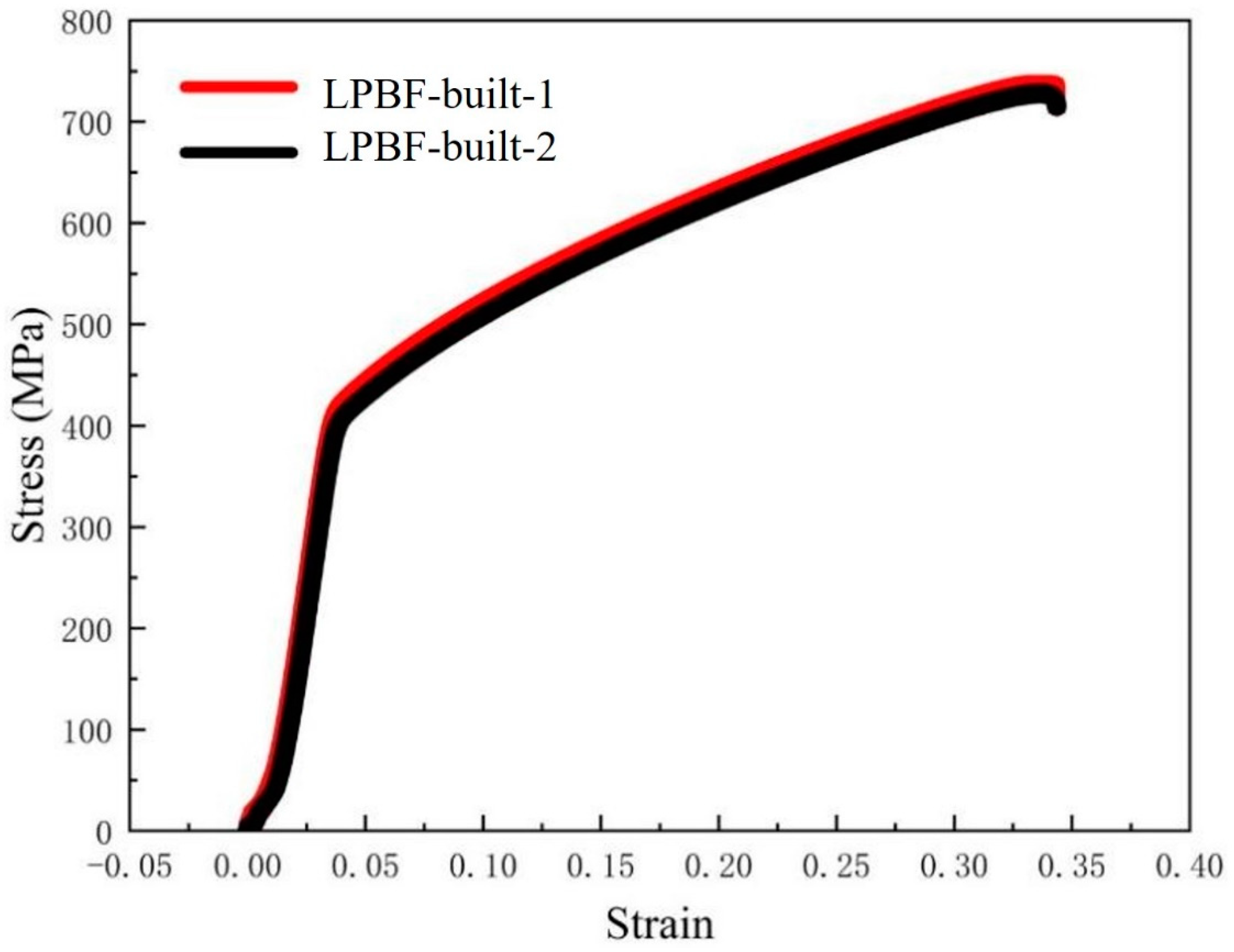
Figure 1. Schematic diagram of the tensile specimens.
Metals 14 00660 g001
Figure 2. XRD patterns of Cu–10Sn powder and LPBF-built specimen.
Metals 14 00660 g002
Figure 3. Microstructure of LPBF-built specimen: (a) parallel to the scanning plane; (b) vertical to the scanning plane; (c) three-dimensional morphology constructed by the top view and side views.
Metals 14 00660 g003
Figure 4. Macroscopic morphology of tensile specimens with different forming angles by LPBF: (a) 0° along the horizontal direction; (b) 15°, 30°, 45°, 60°, 75° and 90° respectively.
Metals 14 00660 g004
Figure 5. Microstructure of LPBF-built specimens with different angles of stretching: (a) 0°; (b) 15°; (c) 30°; (d) 45°; (e) 60°; (f) 75°; (g) 90°.
Metals 14 00660 g005
Figure 6. EBSD mappings of LPBF-built specimens at different tensile angles: (a) 0°; (b) 15°; (c) 30°; (d) 45°; (e) 60°; (f) 75°; (g) 90°; (h) IPF.
Metals 14 00660 g006
Figure 7. Grain size distribution and grain boundary direction of specimens formed by LPBF at different angles: (a) grain size; (b) grain boundary direction.
Metals 14 00660 g007
Figure 8. Schematic diagram of sampling location of LPBF-built tensile specimen and effect of load on columnar grains during tensile experiment.
Metals 14 00660 g008
Figure 9. True stress–strain curves of Cu–10Sn tensile specimens by LPBF (0° angle with different layer thickness).
Metals 14 00660 g009
Figure 10. True stress–strain curves at different angles for Cu–10Sn tensile specimens by LPBF.
Metals 14 00660 g010
Figure 11. Fracture profile of LPBF-built specimens with different angles of tension: (a) 0°; (b) 15°; (c) 30°; (d) 45°; (e) 60°; (f) 75°; (g) 90°.
Metals 14 00660 g011
Table 1. Tensile properties of LPBF-built specimens with different layer thicknesses at 0° angle.
SpecimenYield Strength (MPa)Tensile Strength (MPa)Elongation (%)
LPBF-built-1376 ± 2742 ± 233 ± 0.5
LPBF-built-2374 ± 2736 ± 233 ± 0.5
Table 2. Tensile properties of specimens with different angles by LPBF.
SpecimenYield Strength (MPa)Tensile Strength (MPa)Elongation (%)
386 ± 3723.17 ± 333 ± 0.5
15391 ± 5700.12 ± 528 ± 0.5
30°390 ± 2696.56 ± 226 ± 0.5
45°341 ± 3605.85 ± 319 ± 0.5
60°355 ± 2636.94 ± 223 ± 0.5
75°376 ± 3622.67 ± 321 ± 0.5
90°379 ± 2557.96 ± 212 ± 0.5
Disclaimer/Publisher’s Note: The statements, opinions and data contained in all publications are solely those of the individual author(s) and contributor(s) and not of MDPI and/or the editor(s). MDPI and/or the editor(s) disclaim responsibility for any injury to people or property resulting from any ideas, methods, instructions or products referred to in the content.

