Article

Study on Fracture Behavior and Toughening Mechanisms of Ultra-High-Strength Pipeline Steel

1
College of Chemistry and Life Sciences, Zhejiang Normal University, Jinhua 321004, China
2
Central Iron and Steel Research Institute Company Limited, Beijing 100081, China
3
Zhejiang Innuovo Magnetics Co., Ltd., Dongyang 322118, China
4
PetroChina Planning and Engineering Institute, Beijing 100083, China
*
Author to whom correspondence should be addressed.
Metals 2024, 14(6), 666; https://doi.org/10.3390/met14060666
Submission received: 7 April 2024 / Revised: 19 May 2024 / Accepted: 24 May 2024 / Published: 4 June 2024
(This article belongs to the Special Issue Design, Preparation and Properties of High Performance Steels)

Abstract

:
In this paper, a series of low-temperature CVN (Charpy V-notch impact test) and DWTT (drop-weight tear test) experiments were carried out to deal with the intensifying contradiction of strength and toughness of ultra-high-strength pipeline steel. The fracture behavior and toughening mechanisms of ultra-high-strength pipeline steel were investigated using scanning electron microscopy, transmission electron microscopy and backscattered electron diffraction systems. The results show that DWTT fractures in ultra-high-strength pipeline steel had a variety of unconventional morphological features compared to CVN fractures, including ridge protrusion in ductile fracture conditions and a large-size fracture platform in brittle fracture conditions. Therefore, DWTT fractures contained more information about the material fracturing process, and could better reflect the actual process of material fracturing. In ultra-high-strength pipeline steel, fine-grained granular bainite caused cracks to undergo large deflections or frequent small transitions, which consumed additional energy and improved toughness. In contrast, large-sized granular bainite, which consisted of low-angle grain boundaries, did not effectively prevent crack propagation when it encountered cracks, which was not conducive to improved toughness. Moreover, the M/A constituents in large-sized granular bainite aggregated, cracked, or fell off, which could easily lead to the formation of microcracks and was also detrimental to toughening.

1. Introduction

Increasing the strength of the pipeline steel can correspondingly increase the design pressure and thus the throughput. At the same time, improving the steel grade can also effectively reduce the wall thickness and reduces the difficulty of steel pipe manufacturing, which can not only better ensure the quality of the product, but also saves the amount of steel used and reduces the cost of steel pipe procurement [1,2,3,4].
However, as the strength of the metal materials continues to increase, the toughness decreases significantly, that is, there is an inversion between the strength and the toughness of the metal material. With the increase in the tensile strength of pipeline steel, the upper-platform energy and elongation decrease, and the tough–brittle transition temperature increases [5,6,7]. Arguably, strength is the foundation of the economic construction of pipelines, and toughness is the guarantee of safe pipeline service. This is one of the key issues that researchers are focusing on to improve both strength and toughness.
Generally, Charpy impact toughness is considered to be an essential index of dynamic ductile fracture arrest in gas pipelines. When the strength of pipeline steel exceeds grade X80, the crack arrest toughness index increases significantly, and the contradiction of strength and toughness intensifies. For ultra-high-strength pipeline steel, how to improve its fracture toughness to ensure the safe operation of the pipeline is an important direction of future research and application.
The toughening mechanism below the X100 level has been well studied. There, a good match of strength and toughness was achieved [8,9,10,11,12,13,14]. The contradiction between strengthening and toughening becomes more prominent when the steel grade reaches X100 [7,15,16,17,18,19]. However, research on the toughening mechanism of X100 ultra-high-strength pipe steel is highly insufficient.
In addition, for pipeline steel, especially for large-diameter ultra-high-strength pipeline steel, the results of the Charpy V-notch impact test (CVN) alone cannot completely evaluate the toughness of pipeline steel. The toughness level of a real steel pipe is affected by various factors such as the size, shape and stress state of the sample, and the geometrical constraints for small-size samples in CVN experiments are much smaller than those for actual components. Therefore, it is necessary to evaluate the toughness level of ultra-high-strength pipe steel more accurately using experimental methods that can better simulate real pipes. Among them, the Drop-Weight Tear Test (DWTT) is a relatively common large-scale experimental method in pipeline steel, which can give the relationship between the shear area of the fracture and the temperature. The results of DWTT experiments are in good agreement with those of the blasting test for pipelines [20,21,22].
Since DWTT samples are normally wall-thick pipes, the fracture surface contains all the information on the fracturing process, which plays an essential role in the deep understanding of crack propagation. However, the research on the DWTT of pipeline steel mainly focuses on the factors affecting its performance [23,24,25,26,27,28,29] and the analysis of abnormal fractures [30,31,32,33]. Some scholars have studied the morphological characteristics of some typical regions of DWTT fractures [34,35]. In contrast, there are few reports on the fine characterization and analysis of the DWTT fracture surface.
In this paper, we have investigated the fracture behavior of ultra-high-strength pipe steel by means of a series of temperature CVN experiments and a fine characterization and analysis of the low-temperature DWTT fracture surface, elucidating the mechanism of toughening and providing a theoretical reference for improving the toughness of ultra-high-strength pipe steels.

2. Experimental Material and Procedures

In this work, the experimental steel was produced by industrially hot-rolled steel plates. As shown in Figure 1a, the microstructure of ultra-high-strength pipeline steel was mainly a mixture of granular bainite (GB) and bainitic ferrite (BF). Then, the thermo-mechanical control process schedule is displayed in Figure 1b.
The chemical composition and tensile properties of the experimental steel are listed in Table 1 and Table 2, respectively. Two parallel specimens were processed for the tensile tests. It can be seen that the experimental steel reaches the X100 steel level of strength. X100 ultra-high-strength pipeline steel strips are usually formed by spiral welding. In this welding method, the weld is at a 30° angle to the rolling direction, and the mechanical properties in the 30° direction are the most significant. Therefore, the experimental specimens for the toughness study in this paper were also taken from the direction of 30° from the rolling direction of the steel plate.
A series of CVN tests at 0 °C, −20 °C, −40 °C, −60 °C, −80 °C and −196 °C were performed on the impact test machine (JBN-300B, Wance Testing Machine Co., Ltd., Shenzhen, China) according to ASTM E23 [36]. The specimen size was 10 mm × 10 mm × 55 mm. Three parallel specimens were processed and their mean values were taken after the experiment. A low-temperature DWTT test was carried out on the instrumental drop-weight tear tester (DIT504C, Wance Testing Machine Co., Ltd., Shenzhen, China). The size of the DWTT specimen is referred to standard GB T 8363-2018 [37]. The experimental temperatures were −0 °C and −20 °C, and the size of the specimen was 305 mm × 75 mm × original thickness of the specimen (17.8 mm). Three parallel specimens were processed for the DWTT testing. Liquid nitrogen was used to control the experimental temperature so that the test was in the desired low-temperature state.
Then, the microstructure was represented by scanning electron microscopy (SEM, FEI Quanta 650FEG, FEI, Hillsboro, OR, USA), transmission electron microscopy (TEM, Tecnai G2F20, FEI, Hillsboro, OR, USA) and electron backscattered diffraction (EBSD, Oxford Nordlys F+, Oxford, UK). The SEM specimen was ground, polished, and etched in a 4% Nital solution. The TEM specimens were first mechanically ground to less than 50 μm and punched into a diameter of 3 mm, and then prepared with 6% perchloric acid and 94% methanol for twin-jet electrolytic polishing with the current of 50–80 mA and a temperature of −30 °C. The EBSD specimens were electropolished using an electrolyte consisting of 10% perchloric acid and 90% acetic acid.

3. Results and Discussion

3.1. Fracture Behavior of Ultra-High-Strength Pipeline Steel

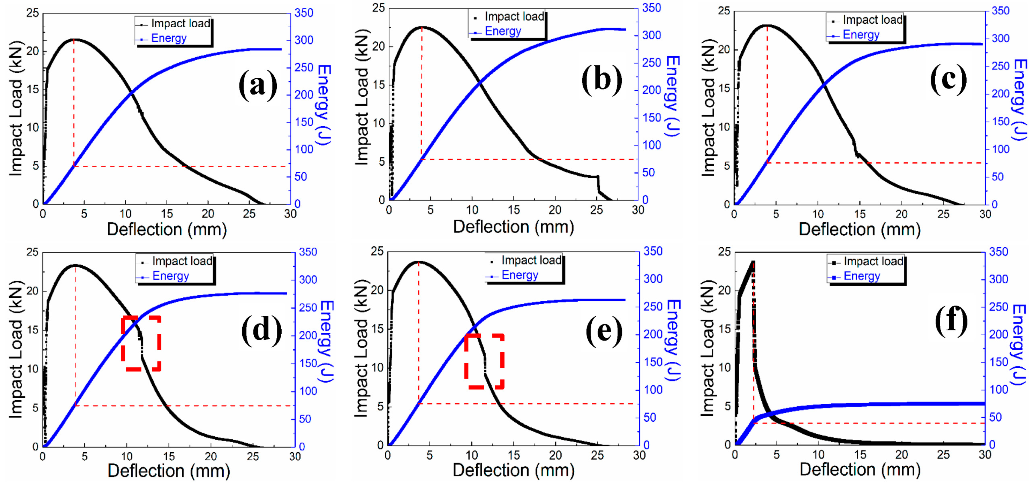
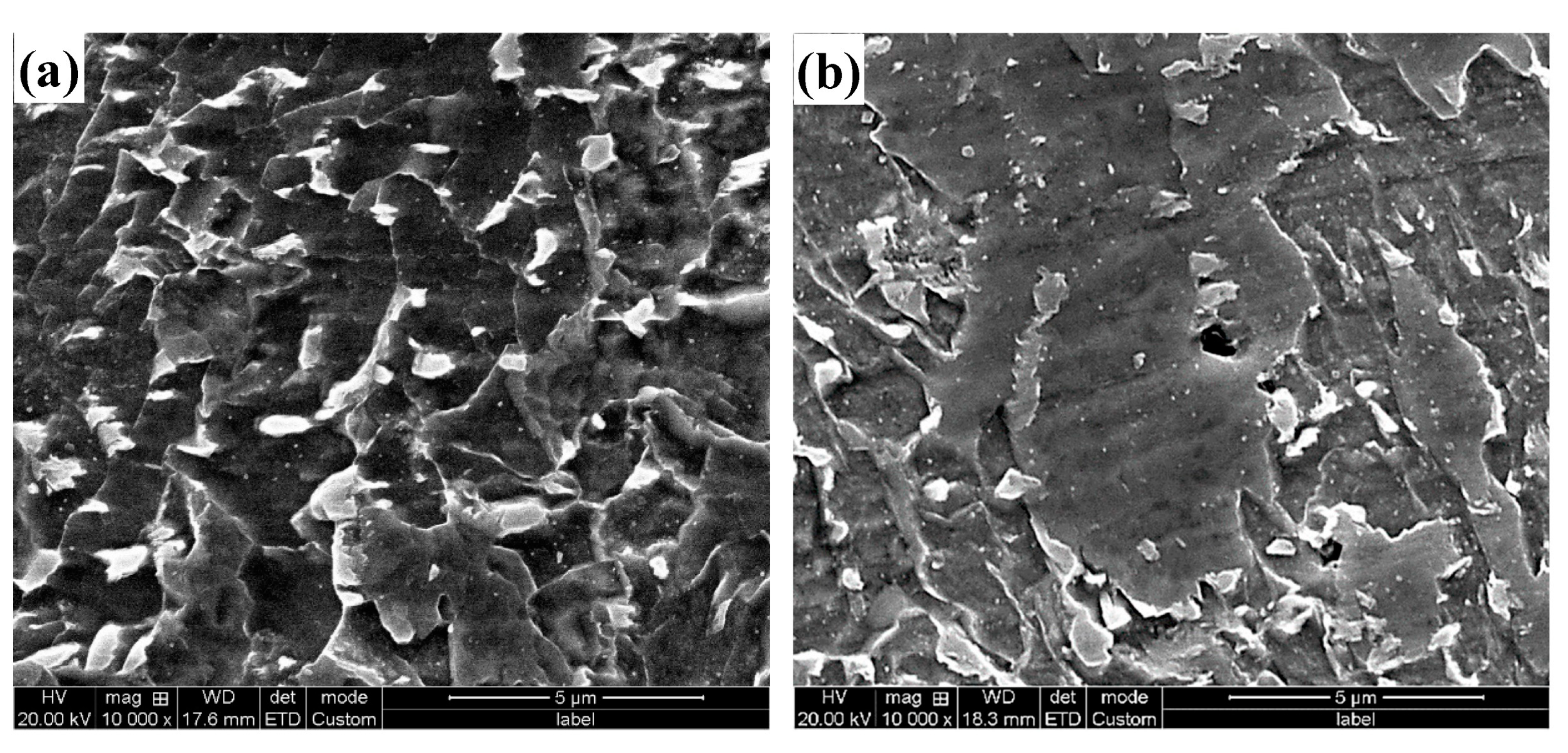
3.1.1. Series of Low Temperature CVN Tests of Ultra-High-Strength Pipeline Steel

The low-temperature CVN results for the series are listed in Table 3. As can be seen from the table, the experimental steel satisfied the standard requirements of API Spec5L up to −60 °C. Then, starting from −40 °C, low values gradually appeared in parallel samples, and the impact energy decreased significantly at −80 °C.
Figure 2 shows the impact fracture morphology of ultra-high-strength pipeline steel at low magnification. The fracture morphology from room temperature to −60 °C showed a large number of small deep dimples and large dimples interleaved. The size and distribution of the large dimples give rise to a distinct pattern. From the point of view of a microscopic mechanism, dimples are a fundamental feature of micropore aggregation and fracture as a result of micropore formation and growth. Larger and deeper micropores indicate that the material undergoes greater plastic deformation during fracture, consumes additional energy, and thus exhibits higher toughness [38]. Therefore, the morphology of the heterogenic dimple indicates a good toughness of the material. At −60 °C, microcracks were observed on the fracture marked by sky blue arrows. In the upper-right triangular frame region, the small dimples disappeared and only a few large dimples could be distinguished, and there were no features of cleavage fracture. Such morphological features indicate the onset of toughness reduction. When the experimental temperature was reduced to −80 °C, brittle fractures occurred in the experimental steel, and large cracks could be seen on the fracture marked by the sky-blue arrow. At −196 °C, the fracture morphology is also brittle fracturing, and the obvious tearing edge (marked by the yellow arrow) on the fracture can be identified as a quasi-cleavage fracture.
At high magnification, a grooved crack could be observed at −80 °C, as shown by the sky-blue arrow in Figure 3a–d, which is usually caused by “delamination” during the fracture process [30,31,32]. A cleavage fracture occurs around the grooved crack in the plastic zone, and the red arrow in Figure 3b marks the dimple band distributed along the left edge of the grooved crack.
When the temperature was reduced to −196 °C, as shown in Figure 3e,f, it could be seen that there were tear edges distributed in different directions on the section (marked by yellow arrows), and the crack stopped propagating when it met the tear edges perpendicular to it (marked by sky-blue arrows), but would expand along the direction parallel to it.
Figure 4 shows the “displacement–load–energy” curve of ultra-high-strength pipeline steel at different temperatures. At the temperature of −60 °C and above, the crack-initiation energy is the same, and the total energy leading to the final fracture of the material is also similar, and the temperature change mainly affects the crack-arresting energy. Brittle fracture features appeared on the curve starting from −40 °C, as shown in the dotted box in Figure 4d,e, but ductile fracturing was still dominant on the whole. When the temperature was reduced to −80 °C, the curve changed significantly, as shown in Figure 4f, representing the disappearance of the plastic deformation region in the ductile fracture stage. This indicates that the fracture at this time transformed into a brittle fracture. In addition, the total energy consumed by the fracture also decreased sharply, indicating that the material failed rapidly and fractures occurred under brittle fracture conditions. This is consistent with the results observed for the fracture sections in Figure 2 and Figure 3.

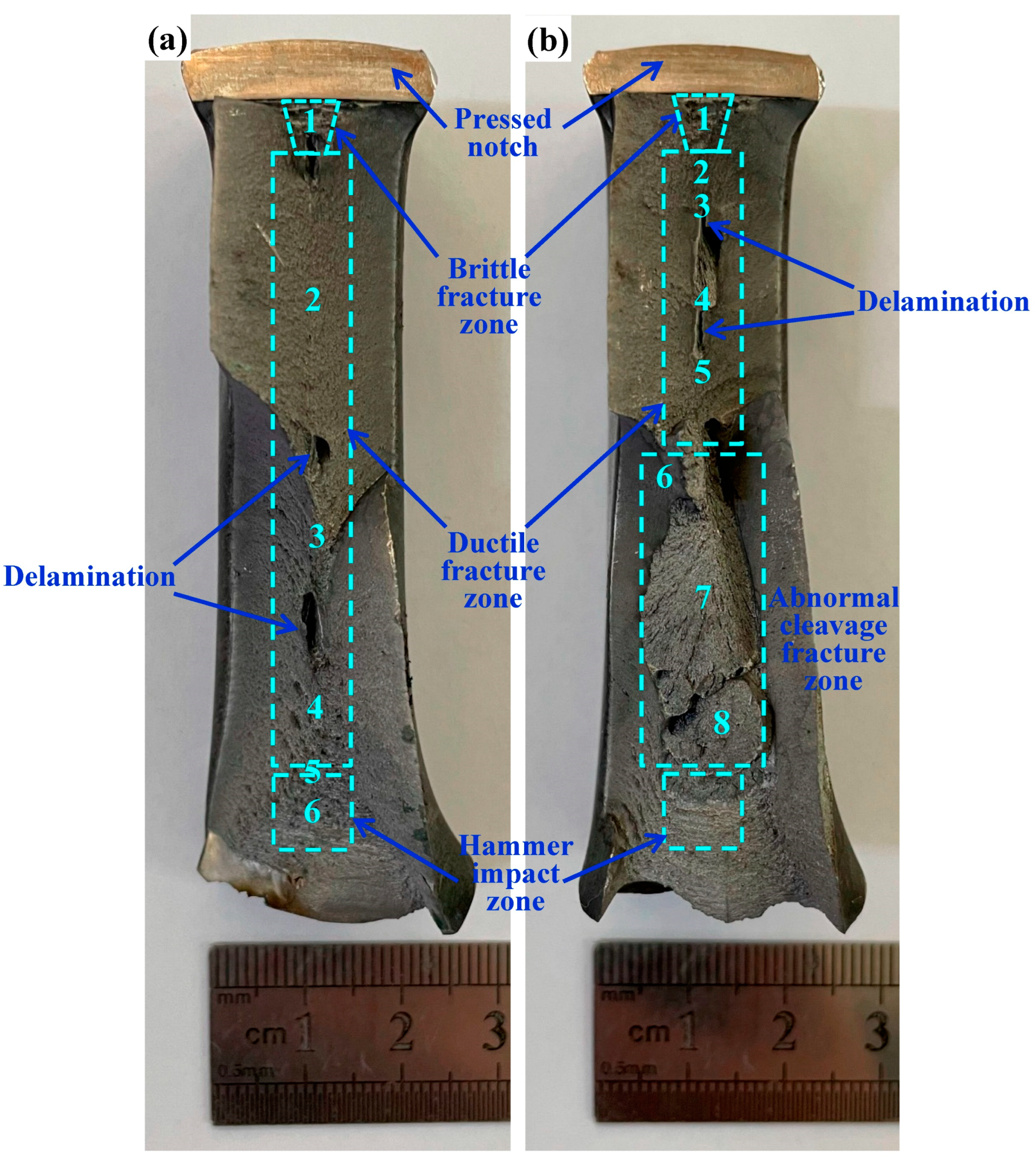
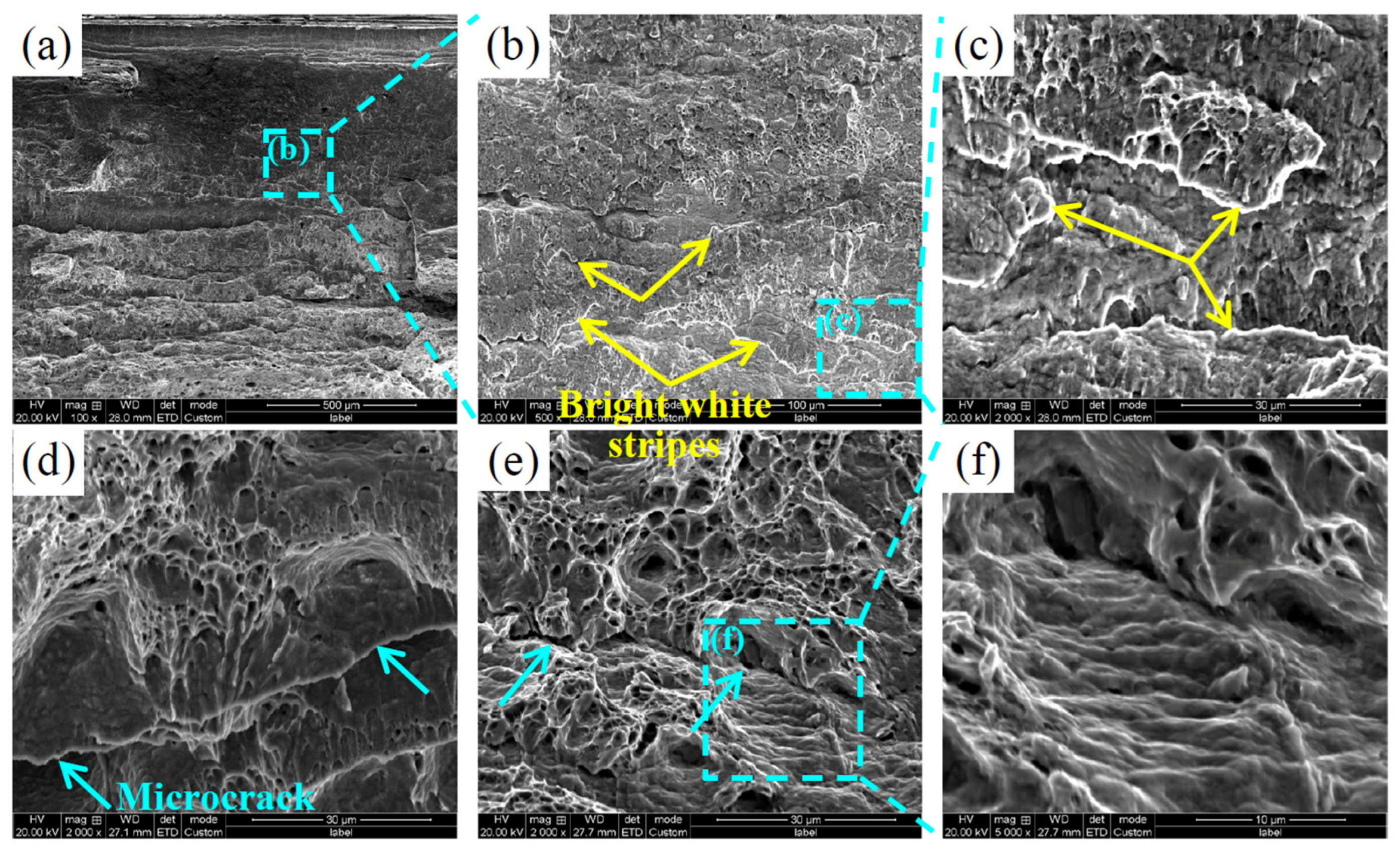
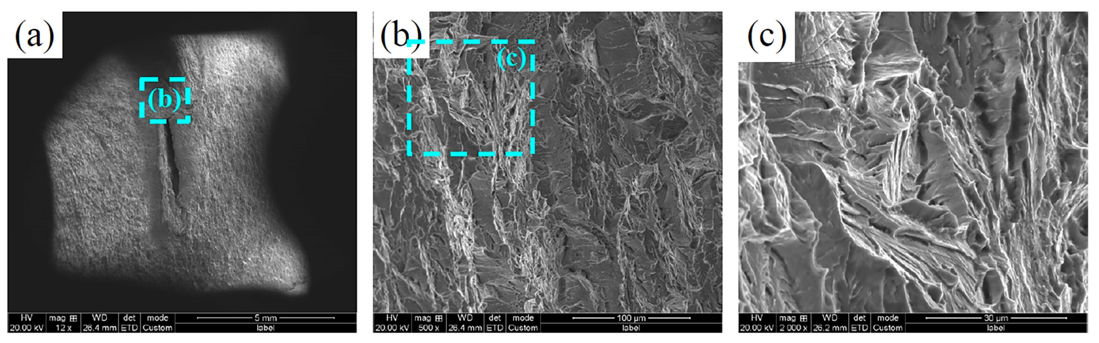
3.1.2. Characterization and Analysis of DWTT Fracture of Ultra-High-Strength Pipeline Steel

Compared to the small-size samples in the CVN experiment, the large-size DWTT sample with full plate thickness is closer to the actual stress and strain state of the pipe at the time of fracture, which better reflects the long-term expansion of the crack in the actual pipe. At the same time, a significant increase in the section length can provide more information about the fracture morphology, which is conducive to an in-depth understanding of the fracturing process.
Figure 5 shows a macroscopic picture of a DWTT fracture in ultra-high-strength pipe steel. At 0 °C and −20 °C, the shear area of the DWTT fracture is 99% and 71.6%, respectively. That is, 85% of the standard index requirements cannot be met when the temperature is reduced to −20 °C.
DWTT fractures can usually be divided into four regions: the pressing notch, brittle fracture zone, ductile fracture zone, and hammer fracture zone. Among them, the brittle and ductile fracture zones are key analysis areas that can give various information about the fracturing process.
In particular, there are delamination defects on the surface of the fracture at both temperatures, and the delamination defect is a typical morphology when the cleavage plane (100) is parallel to the rolled surface during the fracturing process.
Texture analysis in the 30° direction of ultra-high-strength pipeline steel shows that there is a {001}<100> texture in the core structure, which is prone to stratification defects when the {001} texture is distributed along the elongation direction of the flat grain [21,39].
Figure 6 shows the microstructure morphology of position 1 in the brittle fracture zone of a DWTT fracture of ultra-high-strength pipeline steel at 0 °C. Although it had brittle-fracture characteristics in the macroscopic morphology, the SEM morphology at low magnification (Figure 6a) showed a large number of dimples with mixed sizes and some flat plane regions. When the planar region was enlarged (Figure 6b,c), it could be found that the dimples had totally disappeared, leaving only some irregular holes. The dimple disappears because a brittle fracture occurs at this location, that is, the fracture pattern of the material changes from ductile to quasi-cleavage. As a result, the dimple morphology typical of ductile fractures disappears at the fracture. Although it does not have the typical characteristics of a cleavage fracture, its contribution to toughness is extremely limited. Tear edges, which are common in quasi-cleavage fracture morphology, were observed as indicated by the yellow arrows in Figure 6d. In addition, a step-like morphological feature was also observed in some regions, as indicated by the blue arrows in Figure 6e,f, which is also one of the characteristics of quasi-cleavage fracture [40].
Figure 7 shows the microstructure morphology of position 2 in the ductile fracture zone of a DWTT fracture of ultra-high-strength pipeline steel at 0 °C. The fracture morphology was typical ductile fracture morphology with an alternating distribution of small and deep and large-size dimples, showing good toughness, as shown in Figure 7a–c. On the one hand, the formation of dimples is related to the size and distribution of the second-phase particles inside the microstructure, and on the other hand, it is also related to the grain size. The presence of fine granular bainite in ultra-high-strength steel favors the formation of small and deep dimples. In particular, ridge-like protrusion similar to the tear edge of quasi-cleavage features were observed at low magnification, as shown by the yellow arrows in Figure 7d. At high magnification (Figure 7e,f), it could be found that this special morphology was formed by severe plastic deformation of a large number of small dimples. In general, the formation of tear edges consumes a large amount of energy, which increases the impact energy. Microstructures similar to tear edges formed in the ductile fracture zones are not observed in the fracture morphology of the impact specimens.
Figure 8 shows the microstructure morphology of position 3 in the ductile fracture zone of a DWTT fracture of ultra-high-strength pipeline steel at 0 °C. A ridge-like protrusion similar to that at position 2 is also observed at different magnifications, marked by the yellow arrow. Figure 9 shows the microstructural morphology of the ductile fracture zone at different magnifications of location 4. A sharper ridge-like protrusion is also observed, marked by a yellow arrow.
Although the macroscopic morphology of the fracture in Figure 5a shows the characteristics of a brittle fracture, the microscopic morphology remains ductile and also contains the tear-like edge structures observed at positions 2 and 3.
At position 5, the river pattern accompanied by micro-cracks (marked by sky-blue arrows) was observed, which is a typical brittle-fracture feature, as shown in Figure 10. However, position 5 has already reached the hammering zone and is therefore not included in the measurement range.
Figure 11 shows the microstructure morphology at position 6 of the hammering zone at different magnifications. Similarly to position 4, although the fracture morphology in Figure 8a is characterized by brittle fracturing at the macroscopic level, it still consists of ductile-fracture morphology at the microscopic level, as shown in Figure 11a–c. However, some of the dimples had significant plastic deformation (Figure 11d,e), or even had no dimple appearance at all (Figure 11f).
Observations of the microscopic morphology at positions 4 to 6 show that, unlike the fracture of the impact specimen, it is not correct to judge the fracture type by looking at the macroscopic morphological features of the DWTT specimen alone.
Figure 12 shows the microstructure morphology of position 1 in the brittle fracture zone of a DWTT fracture of ultra-high-strength pipeline steel at −20 °C. At low magnification, the fracture was extremely flat (Figure 12a,b), with bright white stripes on the surface (marked by yellow arrows in Figure 12b,c), accompanied by numerous microcracks (marked by blue arrows in Figure 12d,e). The overall morphology was characterized by brittle fracturing, but it differed from the river pattern in a typical cleavage fracture. In addition, an irregularly arranged step shape was observed around the crack, as shown in Figure 12f.
Figure 13 shows the microscopic morphology of position 2. At low magnification, the surface of the fracture is uneven (Figure 13a), and after local magnification, it shows a typical deformed dimple appearance (Figure 13b). Some of the dimples are shallow and small, with irregular morphology (Figure 13c). In some areas, a “ridge” shape consisting of a large number of distorted and elongated small dimples can also be observed (Figure 13e,f), which indicates that large plastic deformation and large energy consumption were experienced during the fracture process.
Figure 14 shows the microscopic morphology of position 3 in the ductile fracture zone of a DWTT fracture at −20 °C. As can be seen from the macroscopic morphology of Figure 5b, delamination defects appeared at this position. More “ridge”-like structures similar to those in Figure 13 could be observed above the delamination defects, as shown in Figure 14a–d. The cracks of the delamination defects are surrounded by a large number of small dimples, as can be seen from the sides of the delamination defects in Figure 14e,f.
Figure 15 and Figure 16 show the microstructures of position 4 and 5 in the DWTT fracture ductile fracture zone of X100 ultra-high-strength pipeline steel at −20 °C, respectively. As can be seen in Figure 15, the micromorphology at position 4 shows typical brittle cleavage-fracture features, including cleavage steps and river patterns. This indicates that local embrittlement occurred at the front end of the delamination defect. At position 5 under delamination defects, although a large number of edges parallel to the fracture direction can be observed at low magnification (Figure 16a), as at position 3, the entire section at high magnification shows deformed dimple morphology (Figure 16b,c), that is, it is still a ductile fracture. According to the results in Figure 14, Figure 15 and Figure 16, the occurrence of delamination defects was independent of the fracture pattern.
The micromorphology of ultra-high-strength pipeline steel at positions 6 to 8 within the brittle fracture zone of a DWTT fracture at −20 °C is shown in Figure 17, Figure 18 and Figure 19, and the micromorphology at different positions in this region is all brittle fracturing. In general, cleavage fracturing is not carried out on a single cleavage plane, but along a set of parallel crystal faces, with cleavage planes at different heights connected by cleavage steps [41]. The blue arrows in Figure 17b,c mark the large cleavage steps, while the trend of the river pattern shows the direction of crack propagation. A large number of deforming dimples (marked by the red arrow) can be observed around the cleavage plane (marked by the blue arrow) in Figure 17e, indicating that the overall fracture pattern is a quasi-cleavage fracture. Position 7 is radial in the macroscopic morphology of Figure 5b and remains as a cleavage fracture in the microscopic morphology of Figure 18. There are a number of secondary microcracks marked by sky-blue arrows along the propagation direction of the crack. In particular, a large number of small dimples were observed on the side of a large cleavage step, as shown in Figure 18e,f, indicating that local plastic deformation also occurred during the brittle fracturing.
At position 8, a large secondary crack forms along the junction of the cleavage steps, as shown in Figure 19. Similar to Figure 18f, one side of the large-size cleavage step has a large number of small dimples that are deformed and elongated. The study of L. Cho et al. [40] pointed out that the formation of ridge-like and large-size step-like microstructures is related to large-angle grain boundaries or lath boundaries, which has a significant hindering effect on the propagation of cracks.
Detailed fracture observations of DWTT specimens indicate that in actual fracturing processes, even if a brittle fracture occurs, local plastic deformation will still accompany the crack propagation.

3.2. Toughening Mechanism of Ultra-High-Strength Pipeline Steel

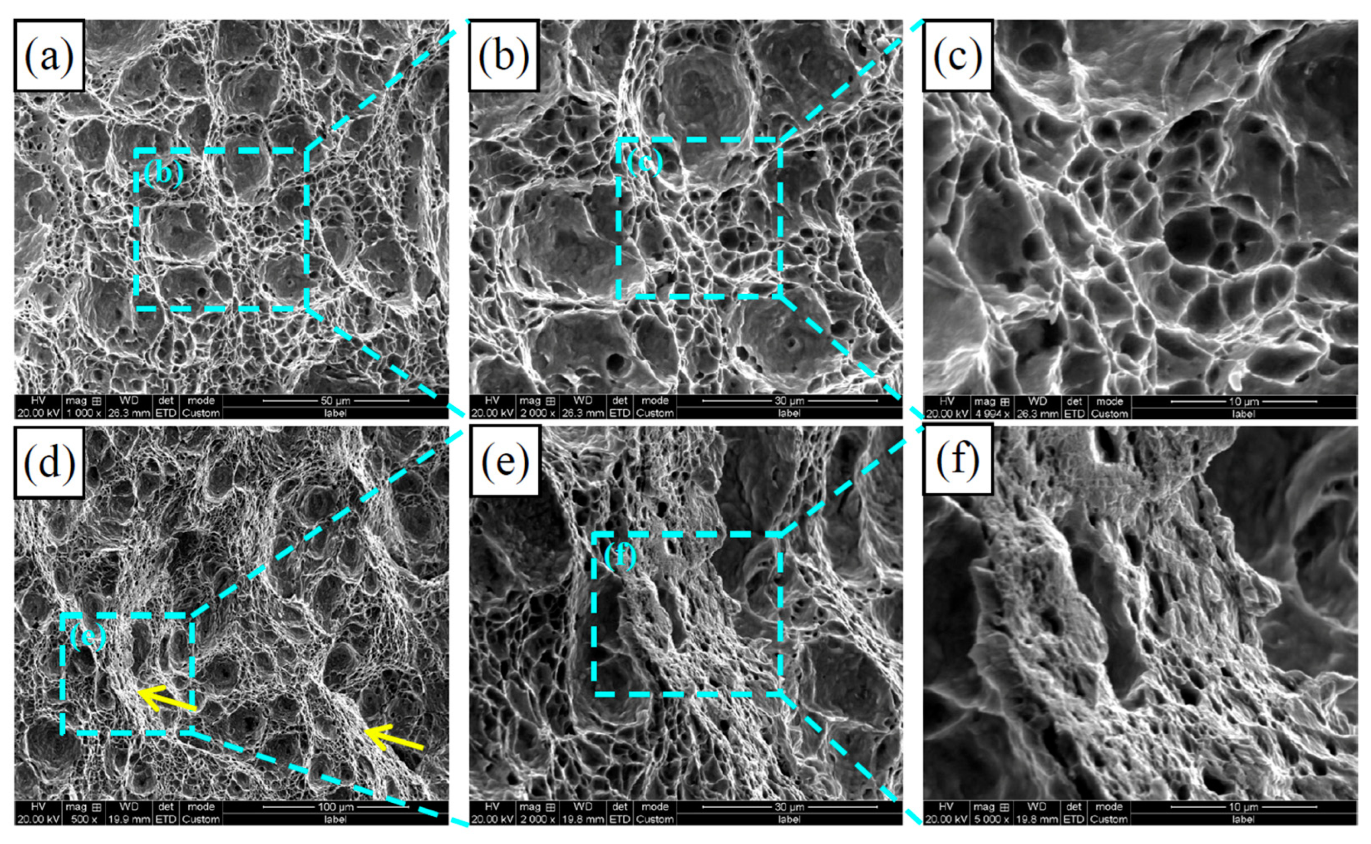
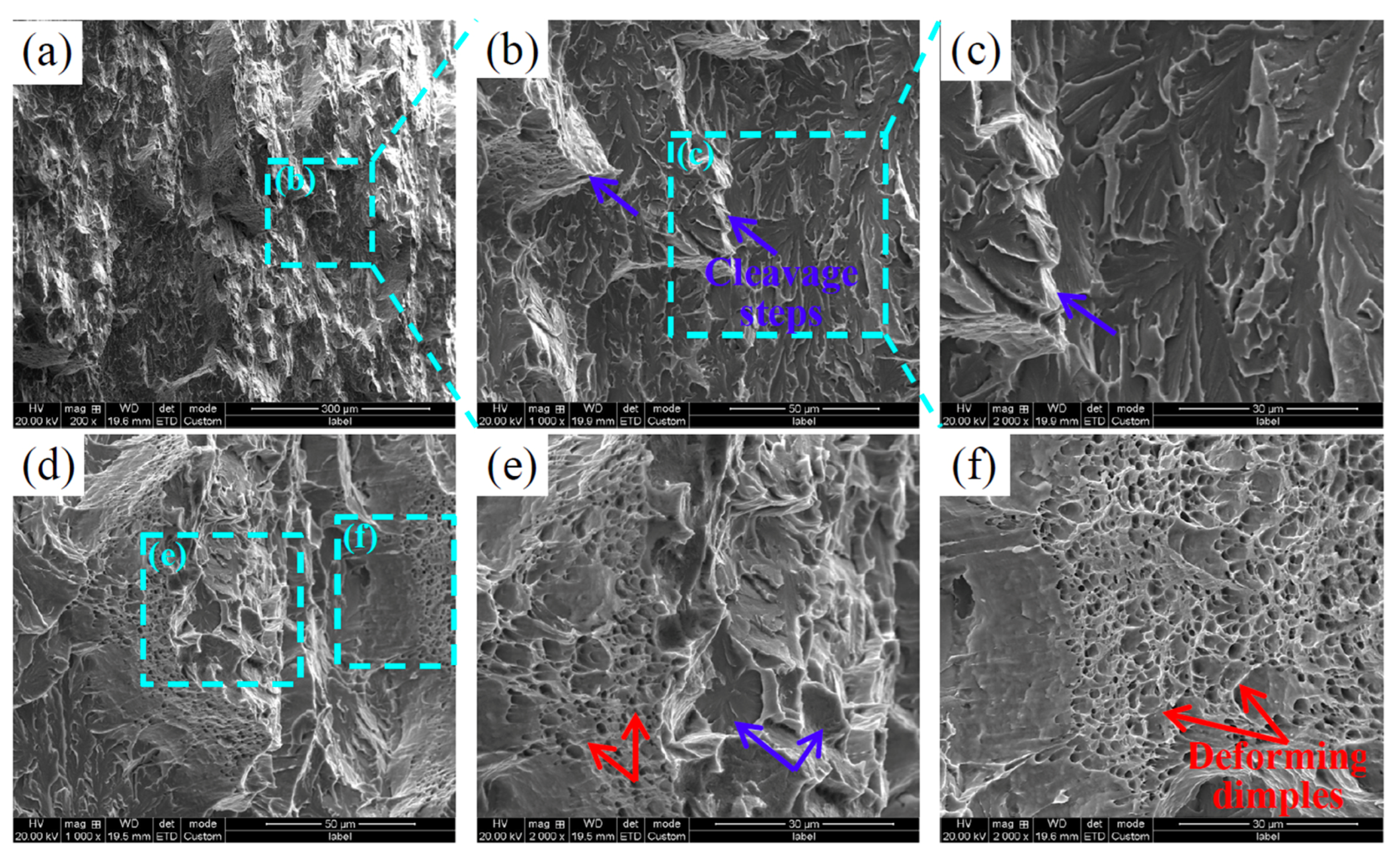
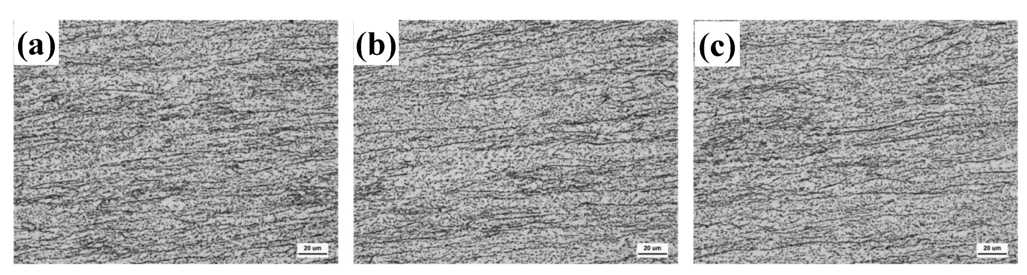
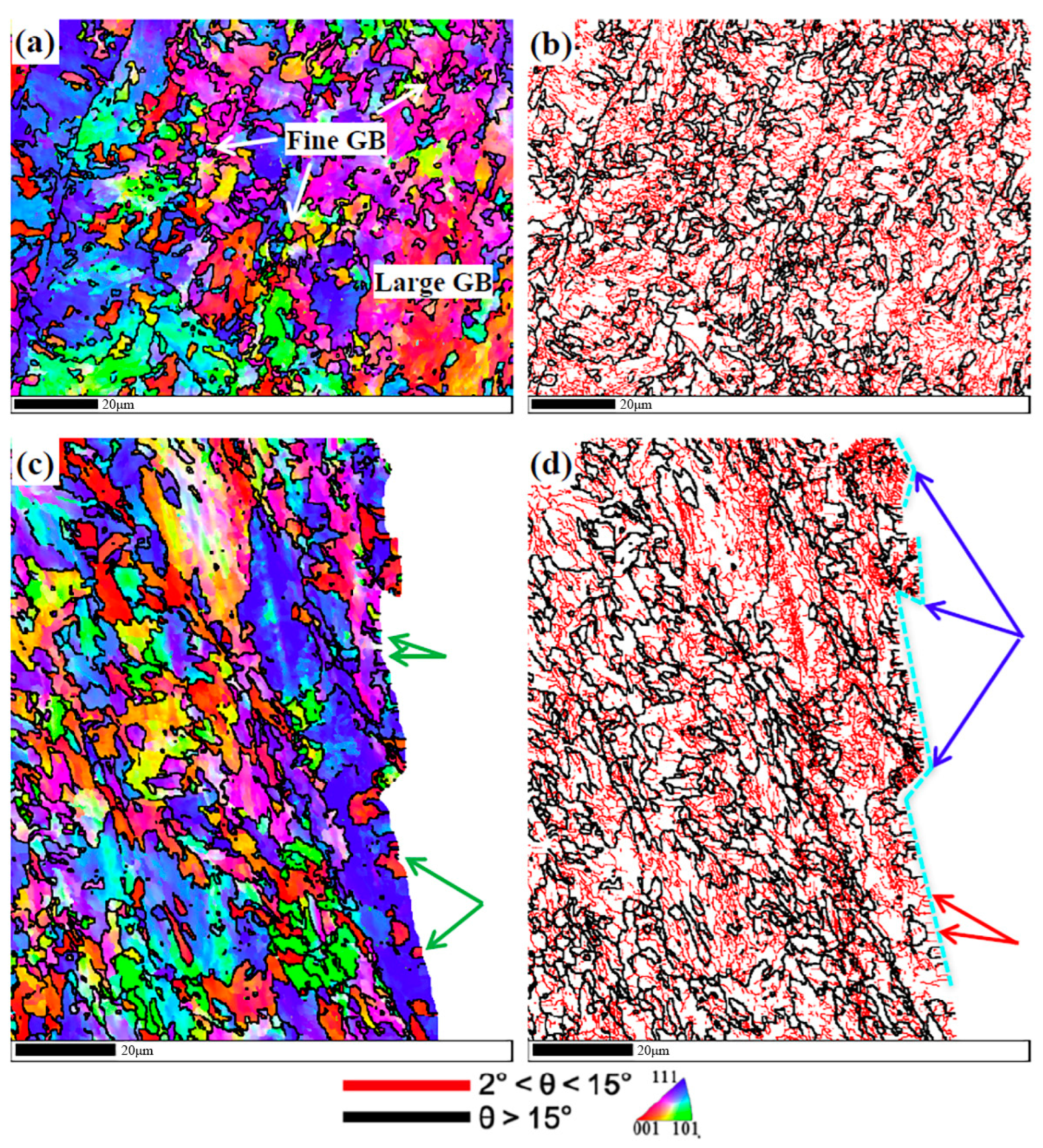
3.2.1. Effect of Deforming Austenite Size on DWTT Performance

Figure 20 shows the parent austenite grains of X100 ultra-high-strength pipe steel in the thickness direction, showing the flat austenite grain boundary morphology after TMCP. The average flat austenite height in the overall thickness direction is about 9 μm. Relevant studies have pointed out that when the flattening height of austenite is less than 9 μm, it can have excellent DWTT performance [9,41]. Thus, the complete flattening of the austenite during the controlled rolling process is one of the reasons for ensuring the toughness of the X100 ultra-high-strength pipe steel.

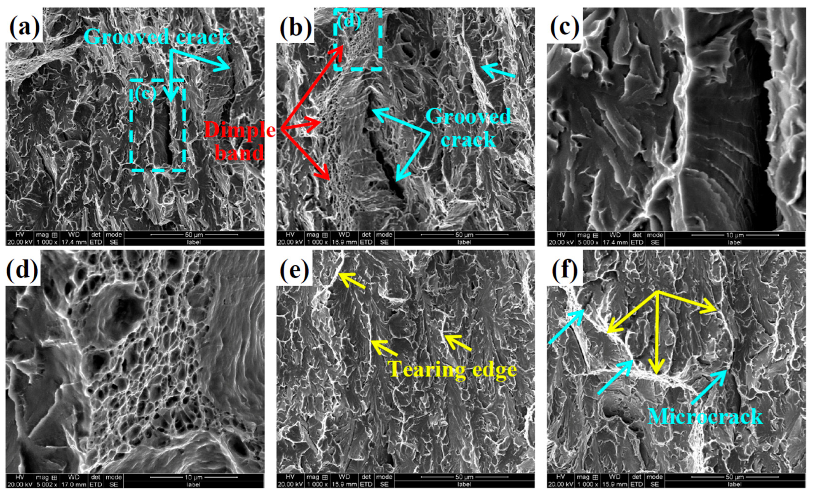
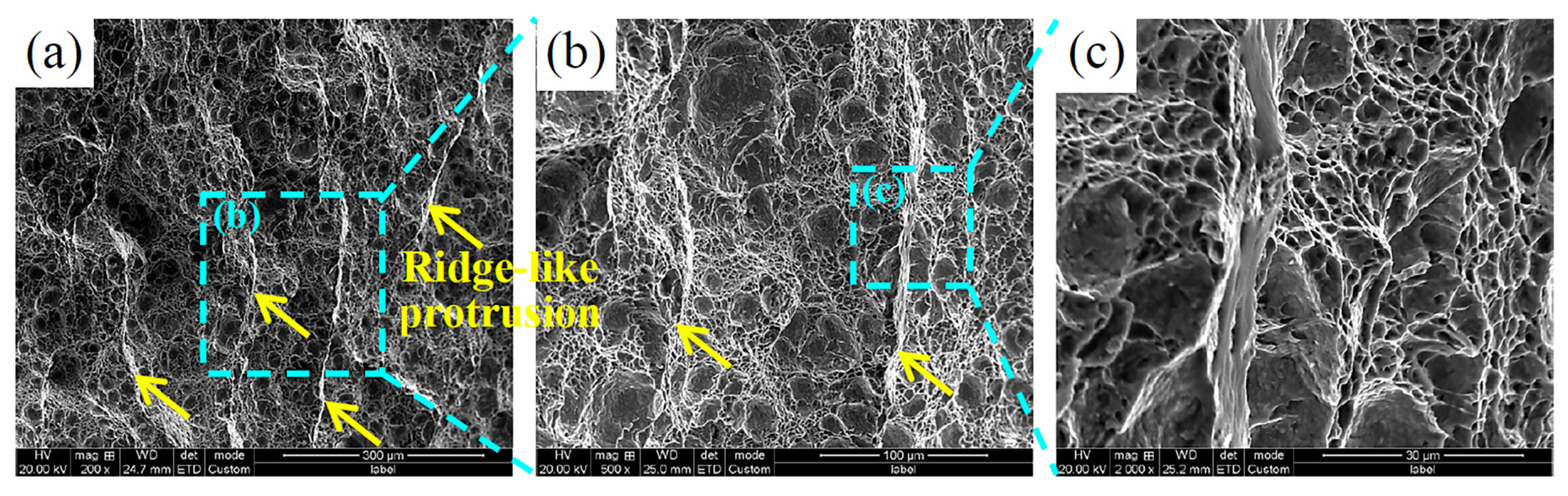
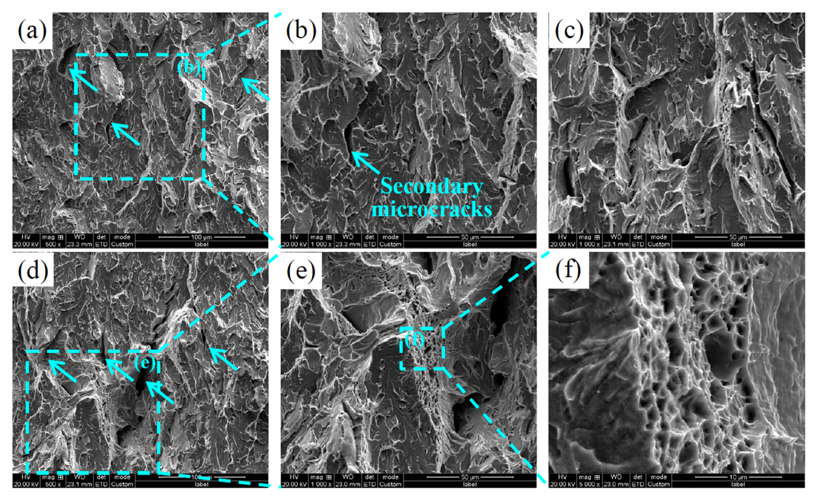
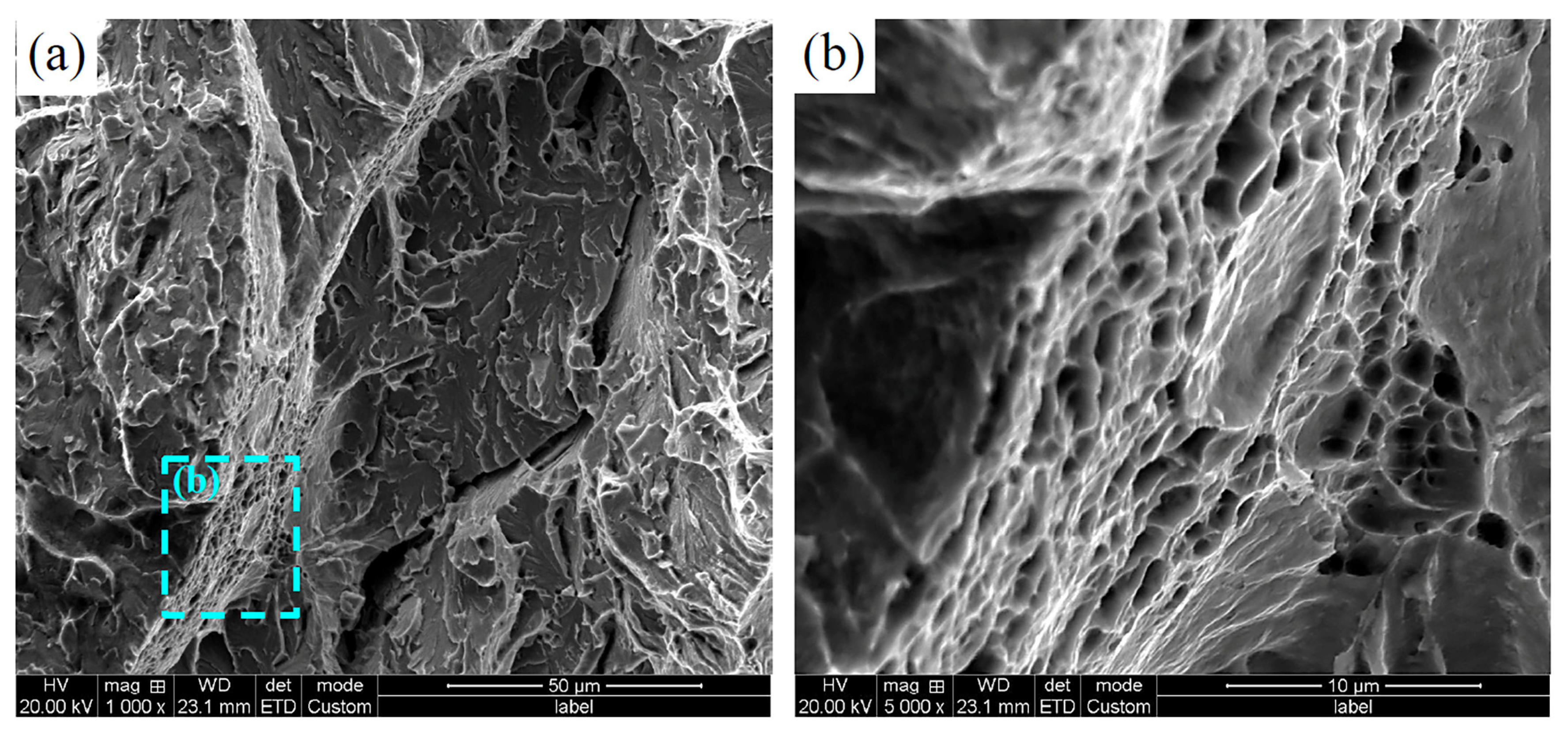
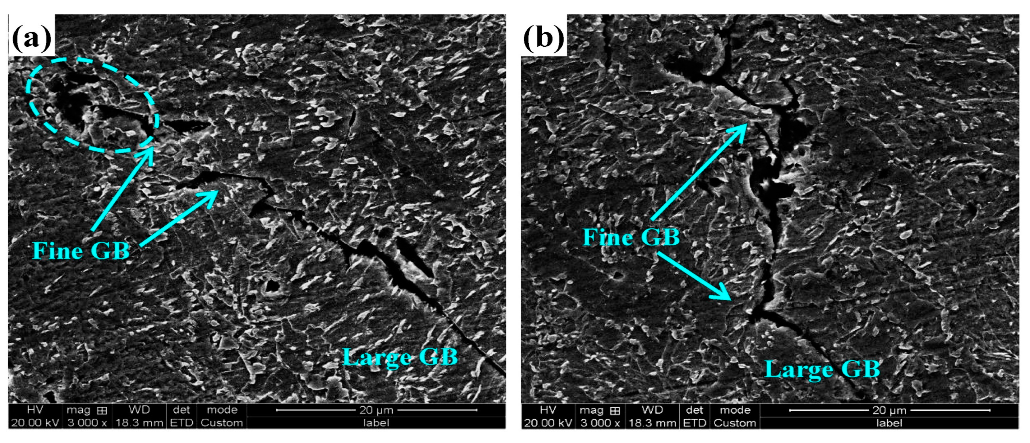
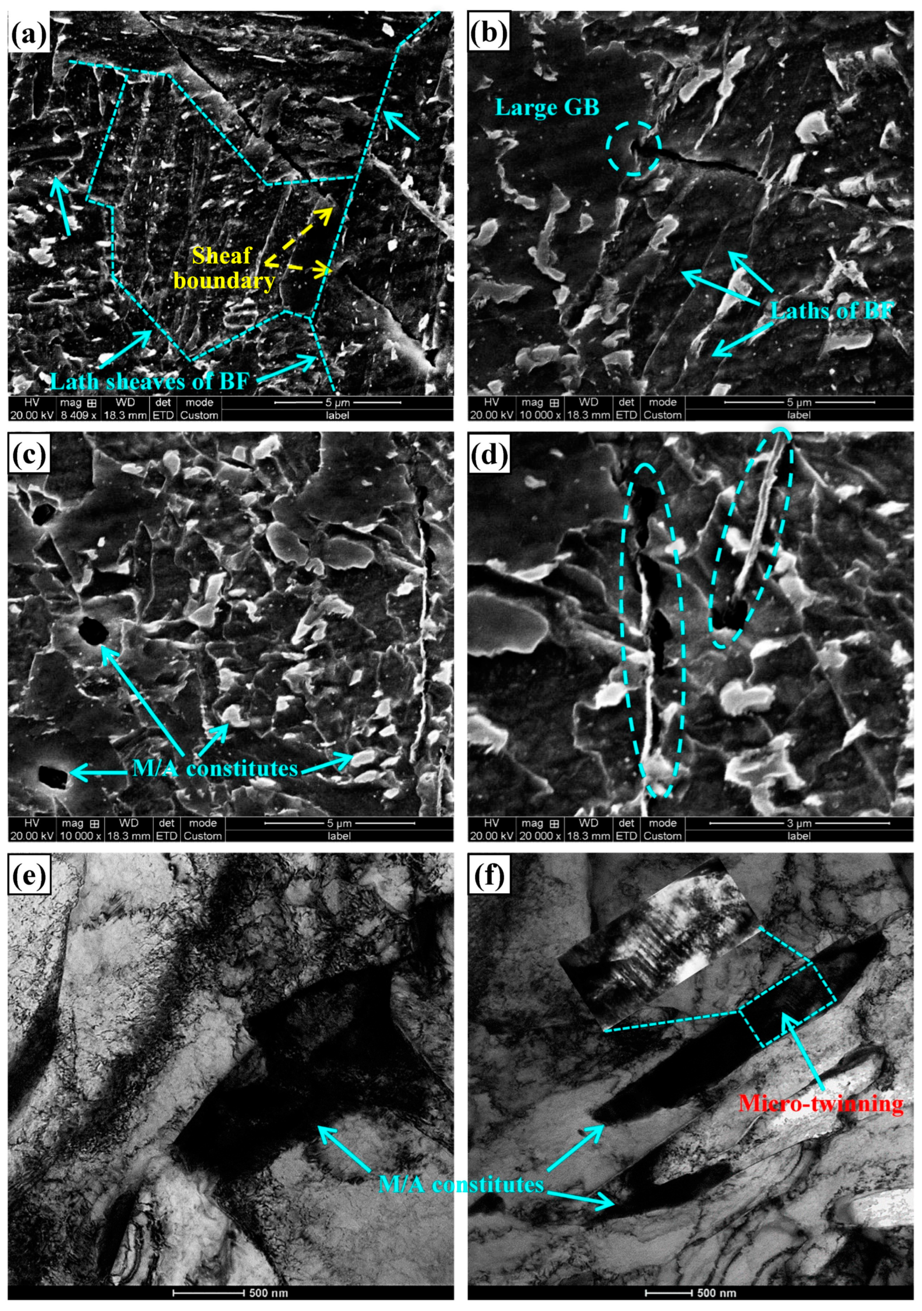
3.2.2. Characterization and Analysis of Crack Propagation Path in Fracture Section

Figure 21 shows the CVN fracture section images of X100 ultra-high-strength pipeline steel at −80 °C and −196 °C. It can be seen that, when the crack propagation encounters the fine-grained granular bainite, large deflections or frequent small turns will occur, which will consume more energy and improve the toughness. Clustered grains in a fine-grained granular bainite will disperse the high stress at the crack tip to the neighboring grains through coordinated deformation, so that the crack will deflect or even stop propagating. In contrast, when the crack propagation encounters a large-sized granular bainite, it will pass directly through it, that is, the large-sized granular bainite lacks an effective blocking effect on the crack and thus has a limited contribution to the toughness. Typical microstructure morphologies of the two granular bainites are shown in Figure 22.
In order to further study the crack propagation process, EBSD pictures of the undeformed region of the fracture section (Figure 23a,b) and the cross-section of the crack propagation path (Figure 23c,d) are presented, respectively. It can be seen from Figure 23a,b that the large-size granular bainite was composed of a large number of low-angle grain boundaries (LAGB, interfaces where the misorientation between adjacent grains is 2°–15°). In contrast, the fine-grained bainite was surrounded by high angle grain boundaries (HAGB, the interface where the misorientation between adjacent grains is greater than 15°), and the internal substructures were few and distributed in clusters. As can be seen from Figure 23c,d, when the crack encountered these small grains in the propagation process, it would have a large transition and change the direction of propagation (marked by dashed and broken lines in Figure 23d). However, when it encountered the large-sized granular bainite, it passed directly through, in agreement with SEM observations. Large-sized granular bainite, which is mainly composed of LAGBs, cannot effectively block crack propagation when it encounters a crack, which is not conducive to toughness enhancement, as indicated by the red arrows in Figure 23d.
It is commonly believed that HAGBs may inhibit crack propagation. However, it could also be found in Figure 23c that, although some of the small grains distributed separately were surrounded by HAGBs, they did not deflect the crack, as indicated by the green arrows. Relevant studies have shown that not all HAGBs have an obstruction effect on crack propagation, and only the interface with an angle of ≥35° between adjacent grain {100} cleavage planes in pipeline steel have an obvious obstruction effect on crack propagation [41]. In contrast, the clumping of fine grains will disperse the high stress at the crack tip to neighboring grains through coordinated deformation, thus deflecting or even preventing crack propagation.
In Figure 23d, high-density substructures can be observed to form inside some of the small grains at several locations where large transitions proceeded, marked by blue arrows, indicating that coordinated deformation occurred when the crack propagation encountered clusters of fine grains. Grain refinement can increase the density of boundaries with a higher special misorientation angle between {110}-planes, which is conducive to suppressing crack initiation [8]. The majority of the dislocations tend to pile along the {110} slip planes as dense dislocation walls to coordinate deformation. At low strains, grains are first divided into cell blocks that are nearly dislocation-free. At higher strains, dislocation tangled zones and lamellar boundaries develop [42]. The cell blocks, dislocation tangled zones and lamellar boundaries all belong to the substructures as marked by blue arrows in Figure 23d. Furthermore, combined with the morphological analysis of the brittle fracture, it can be seen that the large-size step morphology on the brittle zone of the fracture was most likely formed by the giant transition during the propagation of the crack.

3.2.3. Analysis of Secondary Crack in Fracture Section

Figure 24 shows the morphology of secondary cracks in the brittle-fracture cross-section of X100 ultra-high-strength pipeline steel. It can be seen that the microstructure contained a large number of M/A constituents, which were mainly granular and striated. It could also be observed that some of the M/A constituents aggregated and led to crack formation, as shown by the dashed ellipse in Figure 24a. The M/A constituent belongs to the hard and brittle phase in the microstructure of pipeline steel and is generally surrounded by a stress field. If M/A constituents aggregate, the superposition of adjacent stress fields will produce stress concentration, and it is easy to crack and form micro-cracks in the process of deformation [43,44]. These cracks occur with a large deflection in the fine-grained granular bainite region, but pass directly through the large-sized granular bainite.
Figure 25 further shows a high-magnification picture of the secondary crack in the cross-section of the −196 °C impact fracture. When the crack propagation encountered bainite ferrite in ultra-high-strength steel, it could pass directly through the bainite lath, but would deflect or stop at the sheaf boundary (indicated by the yellow dashed line in Figure 25a) or at the granular bainite grain boundary (indicated by the dashed ellipse in Figure 25b). In bainite ferrite, the interface of the lath is LAGB, so there is no blocking effect on the crack.
As a hard and brittle phase in the microstructure, the M/A constituent would also fall off (marked by the sky-blue arrow in Figure 25c) or crack (marked by the dashed ellipse in Figure 25d) during the deformation process, thus becoming the source of cracks. In particular, the strip M/A constituent is prone to micro-cracks and propagates cracks along itself. Figure 25e is a TEM image of a granular M/A constituent in granular bainite, which clearly shows the high density of dislocations inside and the entanglement of the dislocations caused by the surrounding stress field. The TEM image of the strip M/A constituent is then shown in Figure 25f, where micro-twins could be observed, which were twin martensitic transitions from the highly carbon-rich austenite, which had a higher hardness than the granular M/A in Figure 25e and was therefore more prone to micro-cracks.

4. Conclusions

In summary, the following conclusions have been drawn from the above investigation.
(1) Compared to CVN specimens, DWTT specimens of ultra-high-strength pipe steel had a variety of unconventional morphological features. The ductile fracture zone contained a large number of ridge-like protrusions and special-shaped dimples, where the ridge morphology was formed by a mass of dimples stretched along the direction of force. The brittle fracture zone contained a number of large-size fracture platforms. These features had the effect of consuming or hindering the propagation of cracks. Therefore, the DWTT fracture specimen provided more information about the material fracture process and could better reflect the actual process of the material fracturing.
(2) The sufficient flattening of the austenite in the non-recrystallized zone during the controlled rolling process was the basis for obtaining the excellent toughness of ultra-high-strength pipeline steel. During crack propagation, large angular deflections or frequent small transitions occurred when fine-grained granular bainite was encountered, which consumed more energy and improved toughness. When crack propagation encountered bainite ferrite, it would pass directly through the bainite lath composed of low-angle grain boundaries, but would deflect or stop at the lath sheaf boundaries.
(3) Large-sized granular bainite in ultra-high-strength pipe steel consisted of low-angle grain boundaries that did not effectively prevent crack propagation and were not conducive to improved toughness. Moreover, the M/A constituent in granular bainite aggregated, cracked or fell off, which was prone to lead to the formation of cracks and was also detrimental to toughness.
(4) In order to improve the toughness of ultra-high-strength pipe steel, the amount of large-sized granular bainite should be reduced while ensuring sufficient flattening of the deformed austenite.

Author Contributions

Conceptualization, J.G., B.L., X.Z., S.J., X.C., S.F. and D.Z.; Methodology, D.Z., B.L., X.Z., S.J., X.C., S.F., H.Z. and J.G.; Software and Experimental Validation, X.Z., B.L., S.J. and H.Z.; Formal Analysis and Investigation, S.J., B.L., X.Z. and X.C.; Resources, H.Z., S.F. and J.G.; Data Curation, S.F. and H.Z.; Writing-Original Draft Preparation, B.L.; Writing-Review and Editing, X.C.; B.L. and D.Z.; Supervision, S.F. and D.Z.; Project Administration, D.Z. and J.G.; Funding Acquisition, J.G. and D.Z.; All authors have read and agreed to the published version of the manuscript.

Funding

This research received no external funding.

Data Availability Statement

The original contributions presented in the study are included in the article, further inquiries can be directed to the corresponding author.

Conflicts of Interest

Authors Ba Li, Shujun Jia, Xiaoping Chen were employed by the company Central Iron and Steel Research Institute Company Limited, authors Ba Li, Song Fu, Dongliang Zhao, Haonan Zhang were employed by the company Zhejiang Innuovo Magnetics Co., Ltd., author Jie Guo was employed by the company PetroChina Planning and Engineering Institute. All authors declare that the research was conducted in the absence of any commercial or financial relationships that could be construed as a potential conflict of interest.

References

  1. Koo, J.Y.; Luton, M.J.; Bangaru, N.V.; Petkovic, R.A.; Fairchild, D.P.; Petersen, C.W.; Asahi, H.; Hara, T.; Terada, Y.; Sugiyama, M.; et al. Metallurgical design of ultra-high strength steels for gas pipelines. Int. J. Offshore Polar Eng. 2004, 14, 2–10. [Google Scholar]
  2. Witek, M. Possibilities of using X80, X100, X120 high-strength steels for onshore gas transmission pipelines. J. Nat. Gas Sci. Eng. 2015, 27, 374–384. [Google Scholar] [CrossRef]
  3. Duan, L.; Chen, Y.; Liu, Q.; Shu, J.; Cheng, C. Microstructures and mechanical properties of X100 pipeline steel strip. J. Iron Steel Res. Int. 2014, 21, 227–232. [Google Scholar] [CrossRef]
  4. Yoo, J.Y.; Ahn, S.S.; Seo, D.H.; Song, W.H.; Kang, K.B. New development of high grade X80 to X120 pipeline steels. Mater. Manuf. Process. 2011, 26, 154–160. [Google Scholar] [CrossRef]
  5. Guillal, A.; Abdelbaki, N. The optimum use of high-strength steel in the construction of gas transmission pipeline. Int. J. Struct. 2023, 14, 681–699. [Google Scholar] [CrossRef]
  6. Ferino, J.; Fonzo, A.; Di Biagio, M.; Demofonti, G.; Spinelli, C.M.; Karamanos, S.A. Onshore pipeline high-grade steel for challenge utilization. Int. J. Offshore Polar Eng. 2015, 25, 272–280. [Google Scholar] [CrossRef]
  7. Lan, L.; Chang, Z.; Kong, X.; Qiu, C.; Zhao, D. Phase transformation, microstructure, and mechanical properties of X100 pipeline steels based on TMCP and HTP concepts. J. Mater. Sci. Technol. 2017, 52, 1661–1678. [Google Scholar] [CrossRef]
  8. Li, X.C.; Zhao, J.X.; Wang, J.L.; Wang, X.L.; Liu, S.L.; Shang, C.J. Effect of Boundaries on Toughness in High-strength Low-alloy Steels from the View of Crystallographic Misorientation. Mater. Lett. 2019, 259, 126841. [Google Scholar] [CrossRef]
  9. Liu, Q.Y.; Ba, L.; Jia, S.J.; Ren, Y. Toughening Mechanism and Controlling Technology for High-grade Low Temperature Pipeline Steels. Angang Technol. 2020, 10, 8–17. [Google Scholar]
  10. Lei, Y.; Yang, W.; Siyasiya, C.W.; Tang, Z. Effect of Coiling Temperature on Microstructures and Precipitates in High-Strength Low-Alloy Pipeline Steel after Heavy Reduction during a Six-Pass Rolling Thermo-Mechanical Controlled Process. Metals 2024, 14, 249. [Google Scholar] [CrossRef]
  11. Jiang, J.; Zhang, Z.; Guo, K.; Guan, Y.; Yuan, L.; Wang, Q. Effect of Nb Content on the Microstructure and Impact Toughness of High-Strength Pipeline Steel. Metals 2023, 14, 42. [Google Scholar] [CrossRef]
  12. Liu, D.; Dong, Y.; Li, R.; Jiang, J.; Li, X.; Wang, Z.; Zuo, X. Evaluation of Mechanical Properties and Microstructure of X70 Pipeline Steel with Strain-Based Design. Metals 2022, 12, 1616. [Google Scholar] [CrossRef]
  13. Jiang, J.; Zhang, Z.; Zhao, L.; Guan, Y.; Yuan, L.; Wang, Q. Insight into the Role of Mo Content on the Microstructure and Impact Toughness of X80 Thick-Walled Low-Temperature Pipeline Steel. Metals 2023, 13, 1530. [Google Scholar] [CrossRef]
  14. Li, X.C.; Zhao, J.X.; Jia, S.J.; Lu, G.Y.; Misra, R.D.K.; Liu, Q.Y.; Li, B. Ultrafine microstructure design of high strength pipeline steel for low temperature service: The significant impact on toughness. Mater. Lett. 2021, 303, 130429. [Google Scholar] [CrossRef]
  15. Qian, C.; Liang, J.; Huang, Y.; Kang, J.; Gianetto, J.J. A comparative study on constraint parameters for characterizing fracture toughness of X60 and X100 pipe steels. Eng. Fail. Anal. 2022, 141, 106617. [Google Scholar] [CrossRef]
  16. Cheng, S.; Lv, R.; Cheng, F.; Han, B.; Fu, A.; Zhang, X.; Zhang, J.; Feng, Y.; Gao, H. Microstructure and properties of X100 large-deformability pipeline steel based on heating on-line partitioning. Mater. Today Commun. 2023, 35, 105771. [Google Scholar] [CrossRef]
  17. Qi, X.; Huan, P.; Wang, X.; Di, H.; Shen, X.; Sun, Q.; Liu, Z.; He, J. Study on the mechanism of heat input on the grain boundary distribution and impact toughness in CGHAZ of X100 pipeline steel from the aspect of variant. Mater. Charact. 2021, 179, 111344. [Google Scholar] [CrossRef]
  18. Singh, M.P.; Shukla, D.K.; Kumar, R.; Arora, K.S. The structural integrity of high-strength welded pipeline steels: A review. Int. J. Struct. Integr. 2021, 12, 470–496. [Google Scholar] [CrossRef]
  19. Bhardwaj, U.; Teixeira, A.P.; Soares, C.G. Burst strength assessment of X100 to X120 ultra-high strength corroded pipes. Ocean Eng. 2021, 241, 110004. [Google Scholar] [CrossRef]
  20. Hwang, B.; Shin, S.Y.; Lee, S.; Kim, N.; Kim, S.; Kang, K.B. Correlation of crack-tip opening angle for stable crack propagation with Charpy and drop-weight tear test properties in high-toughness API X70 pipeline steels. Metall. Mater. Trans. A 2006, 37, 371–380. [Google Scholar] [CrossRef]
  21. Demofonti, G.; Mannucci, G.; Hillenbrand, H.G.; Harris, D. Evaluation of the suitability of X100 steel pipes for high pressure gas transportation pipelines by full scale tests. Int. Pipeline Conf. 2004, 41766, 1685–1692. [Google Scholar]
  22. Zhu, D.X.K.; Leis, B.N. Ductile-fracture arrest methods for gas-transmission pipelines using Charpy impact energy or DWTT energy. J. Pipeline Sci. Eng. 2013, 12, 259–272. [Google Scholar]
  23. Wang, H.; Bao, Y.; Liu, Y.; Wang, M. Effect of microstructure and grain size on DWTT properties of 22 mm thick X80M hot rolled steel strip. Metall. Res. Technol. 2019, 116, 220. [Google Scholar] [CrossRef]
  24. Nastich, S.Y. Effect of bainite component morphology on the microstructure of X70 low-alloyed steel on thick plate cold resistance. Metallurgist 2012, 56, 196–204. [Google Scholar] [CrossRef]
  25. Shin, S.; Hwang, B.; Lee, S.; Kang, K.B. Effects of notch shape and specimen thickness on drop-weight tear test properties of API X70 and X80 line-pipe steels. Metall. Mater. Trans. A 2007, 38, 537–551. [Google Scholar] [CrossRef]
  26. Hwang, B.; Kim, Y.M.; Lee, S.; Kim, N.; Yoo, J.Y. Correlation of rolling condition, microstructure, and low-temperature toughness of X70 pipeline steels. Metall. Mater. Trans. A 2005, 36, 1793–1805. [Google Scholar] [CrossRef]
  27. Wang, H.; Bao, Y.; Wang, M.; Lin, L.; Li, Z.; Wei, X.D. Effect of inclusions on DWTT properties of thick gauge X80 hot rolled steel strip. Chin. J. Eng. Sci. 2018, 40, 1–10. [Google Scholar]
  28. Zhao, J.; Hu, W.; Wang, X.; Kang, J.; Yuan, G.; Di, H.; Misra, R.D.K. Effect of microstructure on the crack propagation behavior of microalloyed 560 MPa (X80) strip during ultra-fast cooling. Mater. Sci. Eng. A-Struct. 2016, 666, 214–224. [Google Scholar] [CrossRef]
  29. Gesing, M.A.; Simha, C.H.M.; Xu, S.; Tyson, W.R. Geometric and material property dependencies of the plastic rotation factor in the drop-weight-tear test. Eng. Fract. Mech. 2016, 153, 399–406. [Google Scholar] [CrossRef]
  30. Sung, H.K.; Sohn, S.S.; Shin, S.Y.; Lee, S.; Kim, N.; Hwan, S.C. Effects of finish rolling temperature on inverse fracture occurring during drop weight tear test of API X80 pipeline steels. Mater. Sci. Eng. A-Struct. 2012, 541, 181–189. [Google Scholar] [CrossRef]
  31. Hwang, B.; Lee, S.; Kim, Y.M.; Kim, N.; Yoo, J.Y.; Woo, C.S. Analysis of abnormal fracture occurring during drop-weight tear test of high-toughness line-pipe steel. Mater. Sci. Eng. A-Struct. 2004, 368, 18–27. [Google Scholar] [CrossRef]
  32. Fujishiro, T.; Hara, T.; Aihara, S. Effect of plastic deformation on occurrence of abnormal fracture during DWTT. Int. Pipeline Conf. 2012, 45141, 159–165. [Google Scholar]
  33. Yang, Z. The fracture during drop-weight tear test of high-performance pipeline steel and its abnormal fracture appearance. Procedia Mater. Sci. 2014, 3, 1591–1598. [Google Scholar] [CrossRef]
  34. Kang, M.; Kim, H.; Lee, S.; Shin, S. Effects of dynamic strain hardening exponent on abnormal cleavage fracture occurring during drop weight tear test of API X70 and X80 linepipe steels. Metall. Mater. Trans. A. 2014, 45, 682–697. [Google Scholar] [CrossRef]
  35. Majidi-Jirandehi, A.A.; Hashemi, S.H.; Ebrahiminejad, S.; Kheybari, M. Impact of crack propagation path and inclusion elements on fracture toughness and micro-surface characteristics of welded pipes in DWTT. Mater. Res. Express 2021, 8, 106504. [Google Scholar] [CrossRef]
  36. ASTM E23-18; Standard Test Methods for Notched Bar Impact Testing of Metallic Materials. ASTM International: West Conshohocken, PA, USA, 2018.
  37. GB T 8363-2018; Steel-Drop-Weight Tear Tests Method. China Standards Press: Beijing, China, 2018.
  38. Sun, J.; Yang, C.; Guo, S.; Sun, X.; Ma, M.; Zhao, S.; Liu, Y. A novel process to obtain lamella structured low-carbon steel with bimodal grain size distribution for potentially improving mechanical property. Mater. Sci. Eng. A 2020, 785, 139339. [Google Scholar] [CrossRef]
  39. Ye, X.; Cui, S.; Liu, T.; Ma, Q.; Liu, G.; Huang, Z.; Guo, J.; Yin, S. Microstructure Characterization and Strengthening Mechanism Analysis of X100 Pipeline Steel. Coatings 2023, 13, 706. [Google Scholar] [CrossRef]
  40. Cho, L.; Bradley, P.E.; Lauria, D.S.; Martin, M.L.; Connolly, M.; Benzing, J.; Seo, E.J.; Findley, K.; Speer, J.G.; Slifka, A.J. Characteristics and mechanisms of hydrogen-induced quasi-cleavage fracture of lath martensitic steel. Acta Mater. 2021, 206, 116635. [Google Scholar] [CrossRef]
  41. Niu, Y.; Jia, S.; Liu, Q.; Tong, S.; Li, B.; Ren, Y.; Wang, B. Influence of Effective Grain Size on Low Temperature Toughness of High-Strength Pipeline Steel. Materials 2019, 12, 3672. [Google Scholar] [CrossRef]
  42. Venkatsurya, P.K.C.; Misra, R.D.K.; Manohar, M.; Hartmann, J.E. Toward interplay between substructure evolution, dislocation configuration, and yield strength in a microalloyed steel. Mater. Sci. Eng. A 2014, 596, 121–133. [Google Scholar] [CrossRef]
  43. Lan, L.Y.; Qiu, C.L.; Song, H.Y.; Zhao, D.W. Correlation of martensite-austenite constituent and cleavage crack initiation in welding heat affected zone of low carbon bainitic steel. Mater. Lett. 2014, 15, 86–88. [Google Scholar] [CrossRef]
  44. Huda, N.; Midawi, A.R.; Gianetto, J.; Lazor, R.; Gerlich, A.P. Influence of martensite-austenite (MA) on impact toughness of X80 line pipe steels. Mater. Sci. Eng. A-Struct. 2016, 662, 481–491. [Google Scholar] [CrossRef]
Figure 1. (a) Microstructure of ultra-high-strength pipeline steel; (b) Thermo-mechanical control process schedule.
Metals 14 00666 g001
Figure 2. Low magnification SEM images of impact fracture morphology of ultra-high-strength pipeline steel: (a) 0 °C; (b) −20 °C; (c) −40 °C; (d) −60 °C; (e) −80 °C; (f) −196 °C.
Metals 14 00666 g002
Figure 3. High-magnification SEM images of impact fracture morphology of ultra-high-strength pipeline steel: (a,b) −80 °C; (c) enlarged image of the sky-blue dotted box in (a); (d) enlarged image of the sky-blue dotted box in (b); (e,f) −196 °C.
Metals 14 00666 g003
Figure 4. “Deflection–load–energy” curve of ultra-high-strength pipeline steel: (a) room temperature; (b) 0 °C; (c) −20 °C; (d) −40 °C; (e) −60 °C; (f) −80 °C.
Metals 14 00666 g004
Figure 5. Macrograph of DWTT sample fracture of ultra-high-strength pipeline steel: (a) 0 °C; (b) −20 °C. Numbers 1–8 indicate the location of the observations.
Metals 14 00666 g005
Figure 6. Micrograph of position 1 in DWTT fracture of ultra-high-strength pipeline steel at 0 °C. Figures (af) show different regions at position 1, respectively.
Metals 14 00666 g006
Figure 7. Micrograph of position 2 in DWTT fracture of ultra-high-strength pipeline steel at 0 °C. Figures (af) show different regions at position 2, respectively.
Metals 14 00666 g007
Figure 8. Micrograph of position 3 in DWTT fracture of ultra-high-strength pipeline steel at 0 °C. Figures (ac) show different magnifications at position 3, respectively.
Metals 14 00666 g008
Figure 9. Micrograph of position 4 in DWTT fracture of ultra-high-strength pipeline steel at 0 °C. Figures (ac) show different magnifications at position 4, respectively.
Metals 14 00666 g009
Figure 10. Micrograph of position 5 in DWTT fracture of ultra-high-strength pipeline steel at 0 °C. Figures (ac) show different magnifications at position 5, respectively.
Metals 14 00666 g010
Figure 11. Micrograph of position 6 in DWTT fracture of ultra-high-strength pipeline steel at 0 °C. Figures (af) show different regions at position 6, respectively.
Metals 14 00666 g011
Figure 12. Micrograph of position 1 in DWTT fracture of ultra-high-strength pipeline steel at −20 °C. Figures (af) show different regions at position 1, respectively.
Metals 14 00666 g012
Figure 13. Micrograph of position 2 in DWTT fracture of ultra-high-strength pipeline steel at −20 °C. Figures (af) show different regions and magnifications at position 2, respectively.
Metals 14 00666 g013
Figure 14. Micrograph of position 3 in DWTT fracture of ultra-high-strength pipeline steel at −20 °C. Figures (a–f) show different regions at position 3, respectively.
Metals 14 00666 g014
Figure 15. Micrograph of position 4 in DWTT fracture of ultra-high-strength pipeline steel at −20 °C. Figures (ac) show different magnifications at position 4, respectively.
Metals 14 00666 g015
Figure 16. Micrograph of position 5 in DWTT fracture of ultra-high-strength pipeline steel at −20 °C. Figures (ac) show different magnifications at position 5, respectively.
Metals 14 00666 g016
Figure 17. Micrograph of position 6 in DWTT fracture of ultra-high-strength pipeline steel at −20 °C. Figures (af) show different regions at position 6, respectively.
Metals 14 00666 g017
Figure 18. Micrograph of position 7 in DWTT fracture of ultra-high-strength pipeline steel at −20 °C. Figures (af) show different regions at position 7, respectively.
Metals 14 00666 g018
Figure 19. Micrograph of position 8 in DWTT fracture of ultra-high-strength pipeline steel at −20 °C. Figures (a,b) show different magnifications at position 8, respectively.
Metals 14 00666 g019
Figure 20. Metallograph of parent austenite grains of ultra-high-strength pipe steel in thickness direction: (a) side; (b) 1/4 position; (c) center.
Metals 14 00666 g020
Figure 21. Fracture section images of CVN specimen of ultra-high-strength pipeline steel: (ac) −80 °C; (df) −196 °C.
Metals 14 00666 g021
Figure 22. Fracture section microstructures of CVN specimen of ultra-high-strength pipeline steel: (a) fine-grained granular bainite; (b) large-sized granular bainite.
Metals 14 00666 g022
Figure 23. EBSD images of fracture section at −196 °C conditions: (a,c) inverse pole figure; (b,d) grain boundary figure. Green arrows show that the HAGBs did not deflect the crack. Blue arrows show that high-density substructures proceeded large transitions. Red arrows show that LAGBs could not effectively block crack propagation.
Metals 14 00666 g023
Figure 24. Microstructure of secondary cracks in fracture cross-section of CVN specimen at −196 °C conditions. Figures (a,b) show different regions at fracture cross-section.
Metals 14 00666 g024
Figure 25. (ad) High-magnification picture of secondary cracks in fracture cross-section of CVN specimen at −196 °C conditions; (e,f) TEM image of typical M/A component in granular bainite.
Metals 14 00666 g025
Table 1. Chemical composition of experimental steel (wt. %).
CSiMnPSNbVTiMoNiCrCu
0.060.271.930.0090.0010.0890.0270.0190.270.260.290.27
Table 2. Tensile properties of experimental steel at 30° direction.
NameRt0.5/MPaRm/MPaRt0.5/RmA/%
Specimen-17008050.8728.5
Specimen-27108050.8829
Table 3. Impact energy of experimental steel at 30° direction (J).
Temperature0 °C−20 °C−40 °C−60 °C−80 °C−196 °C
1310315292253695.9
2299300291260744.2
3310298246271433.6
Mean value306304276261624.6
Disclaimer/Publisher’s Note: The statements, opinions and data contained in all publications are solely those of the individual author(s) and contributor(s) and not of MDPI and/or the editor(s). MDPI and/or the editor(s) disclaim responsibility for any injury to people or property resulting from any ideas, methods, instructions or products referred to in the content.

