Article

Effect of Si Content on Microstructure and Properties of Low-Carbon Medium-Manganese Steel after Intercritical Heat Treatment

by
Zihan Hu
and
Hanguang Fu
*
School of Materials Science and Engineering, Beijing University of Technology, Beijing 100124, China
*
Author to whom correspondence should be addressed.
Metals 2024, 14(6), 675; https://doi.org/10.3390/met14060675
Submission received: 11 May 2024 / Revised: 4 June 2024 / Accepted: 5 June 2024 / Published: 6 June 2024
(This article belongs to the Special Issue Design, Preparation and Properties of High Performance Steels)

Abstract

:
The microstructure and mechanical properties of three kinds of low-carbon medium-manganese steels with different Si contents under an intercritical heat treatment process were studied. The results show that the microstructure of the test forged steel is mainly composed of ferrite and pearlite. After 900 °C complete austenitizing quenching + 720 °C intercritical quenching, the microstructure of the test steel is mainly composed of ferrite and martensite. With the increase in Si content, the microstructure becomes finer and more uniform. The microstructure of the test steel after 900 °C complete austenitizing quenching + 720 °C intercritical quenching + 680 °C intercritical tempering is dominated by ferrite and tempered martensite, with a small amount of retained austenite and cementite. As the Si content increases, the boundaries between ferrite and tempered martensite become more clear. The tensile strength and hardness of the test steel increase with the increase in Si content, while the elongation first increases and then decreases; the comprehensive performance of the test steel is the best when the Si content is 0.685 wt. %, with a tensile strength of 726 MPa, a yield ratio of only 0.65, the highest elongation of 30.5%, and the highest strong plastic product of 22,143 MPa.%.

1. Introduction

The demand for low-cost, high-strength, and high-toughness low-carbon alloy steel in the automotive, power, machinery, and metallurgical industries is increasing [1,2]. Research has found that a certain amount of metastable austenite in steel can significantly improve its mechanical properties while significantly improving its plasticity and toughness [3,4]. Metastable austenite includes both retained austenite and reverse-transformed austenite. Austenite that remains in the structure without undergoing martensitic transformation during cooling is called retained austenite, and austenite that is regenerated by the inverse transformation of martensite or bainite during tempering is called reverse-transformed austenite [5].
In the 1970s, Miller [6] first proposed a low-carbon medium-manganese steel with a chemical composition of 0.11C-5.7Mn (wt. %) and obtained metastable austenite with a stability of 20–40% in the steel through intercritical heat treatment. Morris et al. [7] found that the steel with a chemical composition of 0.04C-5Mn-0.2Mo (wt. %) had good toughness at −196 °C after quenching and intercritical heat treatments, which was attributed to the refinement of the microstructure and the metastable austenite formed during intercritical annealing. Lee et al. [8] showed that the intercritical heat treatment process can obtain reverse-transformed austenite at room temperature for 3–10% Mn or Ni steel, but the effect is not obvious for low-carbon steel with a Mn content less than 3%.
In order to obtain a high content and metastable austenite in low-carbon low-alloy steel, Xie et al. [9] proposed a new three-step heat treatment process. This process involves heating the steel to near the Ac1 temperature after the two-step intercritical heat treatment, allowing the austenite to further enrich carbon and alloy elements. Xi et al. [10] conducted a three-step heat treatment on low-carbon copper-bearing steel, obtaining 14.7% retained austenite, with a tensile strength of 900 MPa, an overall elongation increased from 13.2% to 22.2%, and an impact energy at −40 °C increased from 100 J to 219 J. Huang et al. [11] conducted a three-step heat treatment on 0.12 C-3.0 Mn low-carbon medium-manganese steel, obtaining a maximum retained austenite content of 15%, a total elongation exceeding 30%, and an impact energy at −80 °C reaching 200 J. Li et al. [12] conducted a three-step heat treatment on low-alloy TRIP steel, finding that the retained austenite content of the test steel increased significantly, and the yield strength slightly decreased with increasing tempering temperature, but the plasticity and toughness significantly improved with increasing tempering temperature.
Adding alloy elements is a method to adjust the structure and properties of medium-manganese steel. Elements such as C, Mn, Si, Al, Ni, and Ti can affect the structure and properties of medium-manganese steel. C, as a solid solution strengthening element and austenite-stabilizing element, has a significant impact on the microstructure and properties of medium-manganese steel. As the content of C increases, the solid solution strengthening effect and the enhancement in austenite stability increase [13]. Mn is the most important element for stabilizing austenite, and the content of austenite in the structure increases with the increase in Mn content [14]. The addition of the Al element can promote the formation of ferrite and improve the plasticity of medium-manganese steel [15]. Cai et al. [16] added the Ti element to medium-manganese steel and found that the grain size of the steel was refined, the hardness was higher, and the wear resistance was better. Zhang et al. [17] added the Ni element to medium-manganese steel, and through the combination of TRIP and NiAl precipitation mechanisms, the steel had excellent tensile strength (961 MPa) and elongation (53%). The increase in Si content can inhibit the precipitation of carbides, promote the enrichment of the C element in austenite, delay the decomposition process of austenite, and improve the stability of residual austenite [18,19]. Si can also refine the grain size and improve the tensile strength and elongation of steel [20]. Song et al. [21] studied the effect of Si on martensite in medium-manganese steel and found that the increase in dislocation density by Si significantly improved the tensile strength of the steel, and the formation of the dislocation cell structure gave the steel good elongation. At present, no researchers have studied the effect of Si content on the intercritical heat treatment of low-carbon medium-manganese steel.
Si is a common alloying element in steel and is inexpensive. In order to improve the strength and toughness of low-carbon medium-manganese steel, this article studies low-carbon medium-manganese steel with different Si contents through intercritical heat treatment to explore the evolution of the microstructure and mechanical properties of low-carbon medium-manganese steel with different Si contents.

2. Materials and Methods

2.1. Material Casting and Forging

The test steel was melted in a vacuum induction melting furnace under argon protection, using industrial pure iron, electrolytic manganese, 75% Si iron, high-purity graphite, etc. The metal mold was poured into a φ70 mm × 200 mm ingot, and the chemical composition of the test steel was determined using an Optical Emission Spectrometer, as shown in Table 1. The ingot was repeatedly thickened and forged into a plate-like blank with a thickness of 30 mm, with a forging ratio of 5. The initial forging temperature was 1200 °C, the final forging temperature was 920 °C, and it was air-cooled to room temperature. The size of the forged steel plate was 165 mm × 130 mm × 30 mm, and all samples were taken from the forged steel plate.

2.2. Material Heat Treatment

The CCT curves of the test steels with different Si contents calculated using JMatPro are shown in Figure 1. Table 2 was made based on the calculation results of JMatPro. It shows the austenite transformation end temperature Ac3, pearlite-to-austenite transformation temperature Ac1, and martensite start transformation temperature Ms and end transformation temperature Mf of the test steels with different Si contents calculated using JMatPro. From the table, as the Si content increases, the austenite transformation temperature gradually increases, while the martensite transformation temperature gradually decreases. This is because Si, as a non-carbide-forming element, usually exists in the form of solid solution atoms in ferrite and austenite, which increases the activity of carbon and reduces the activity of iron atoms, thereby increasing the diffusion activation energy and requiring higher temperatures to achieve austenitization [22]. As the Si content increases, the transformation range of ferrite in the test steel increases, while the transformation range of bainite decreases, indicating that when the cooling rate is between 100 and 0.01 °C/s, the start transformation temperature of ferrite gradually increases, and the start transformation temperature of bainite gradually decreases with the increase in Si content. This is because during the austenitization process, the accumulation of Si in ferrite increases the chemical potential of C in ferrite, thereby increasing the driving force for C element diffusion into austenite, effectively improving austenite stability while avoiding the formation of pearlite and bainite during cooling, making it easier to obtain martensite [23].
The specific heat treatment process is shown in Figure 2. First, the billet is heated to 900 °C for 30 min for the complete austenitizing heat treatment. Then, the intercritical quenching treatment is carried out. To obtain ferrite’s and martensite’s dual-phase structure, an appropriate temperature should be set. A lower temperature will lead to excessive ferrite, a higher temperature, and higher martensite content. The temperature of the two-phase zone is 720 °C. The sample is heated to 720 °C for 20 min and water-cooled to room temperature, then heated to 680 °C for 20 min for tempering.

2.3. Microstructure Observation and Mechanical Property Testing

According to the standard GB/T 228.1-2021 “Metallic materials-Tensile testing-Part 1: Method of test at room temperature” [24], the heat-treated specimens were processed into plate-shaped tensile specimens with a total length of 110 mm and a gauge length of 30 mm. The tensile properties were tested at room temperature on a UTM5305 electronic universal testing machine at a tensile rate of 3 mm/min, and the average value of the three specimens was taken as the performance.
The Brinell hardness of the samples was measured according to the standard GB/T 231.1-2018 “Metallic materials-Brinell hardness test-Part 1: Test method” [25]. The diameter of the hard alloy ball was 2.5 mm, the nominal value of the test force was 1839 N, and the ratio of the test force to the ball diameter squared was 30 N/mm2. Take a sample with a size of 10 mm × 10 mm × 20 mm as a hardness testing sample; four positions were selected for each sample for measurement.
The heat-treated samples were sequentially ground with 80-mesh, 240-mesh, 400-mesh, 1000-mesh, 1500-mesh, and 2000-mesh SiC sandpaper, followed by mechanical polishing with diamond polishing paste with a particle size of W2.5. After polishing, they were etched using a 4% nitric acid alcohol reagent, and microstructure observation and analysis were performed using a field-emission scanning electron microscope (ZEISS Gemini Sigma 500, Carl Zeiss AG, Oberkochen, Germany).

3. Results and Discussions

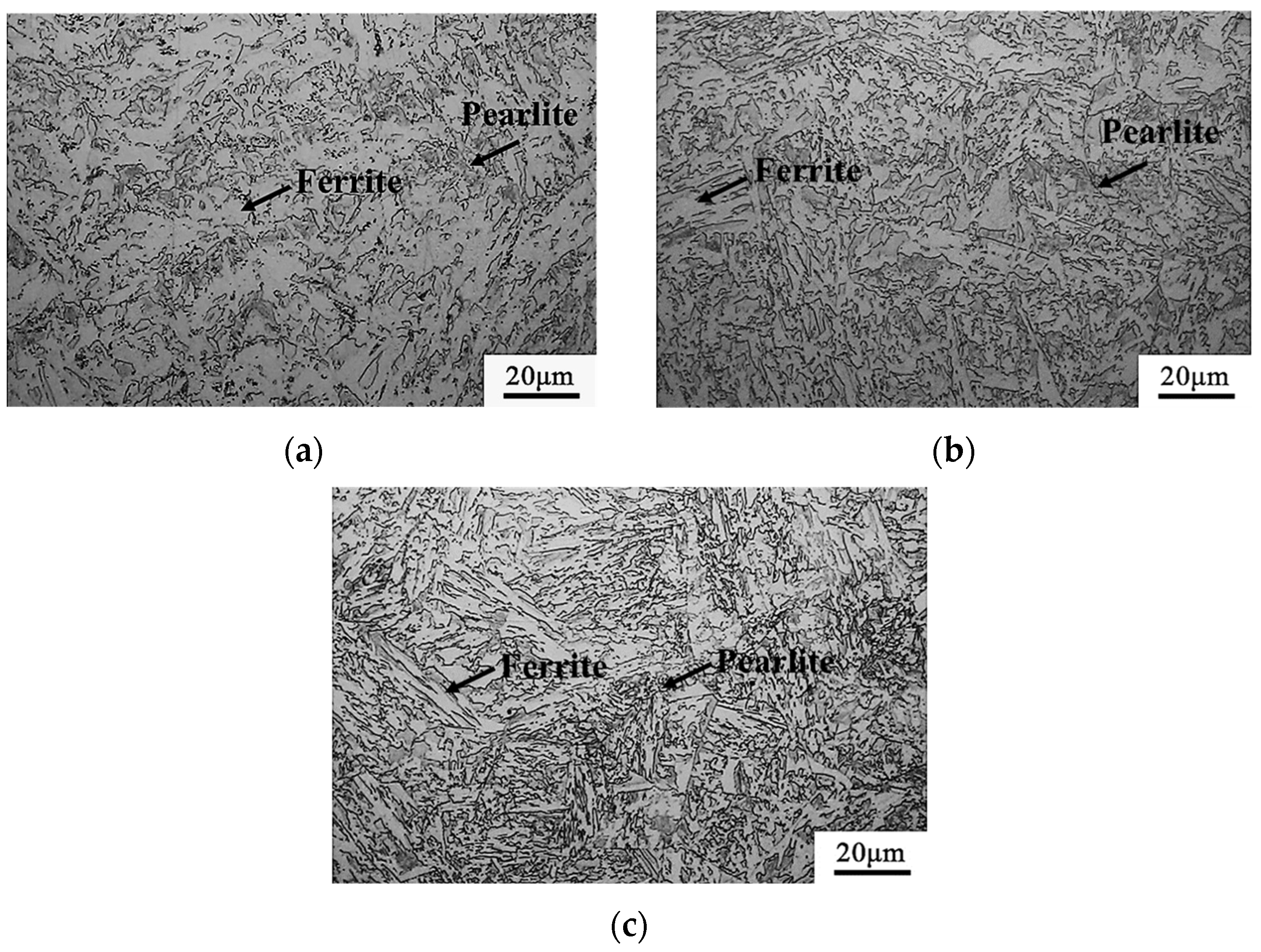
3.1. Microstructure and Hardness of Forged Plate of Test Steel

Figure 3 shows that the microstructure of the tested forged steel is mainly composed of ferrite and pearlite, which is a typical structure of low-carbon low-alloy steel. In Figure 4, the average values of the Brinell hardness of the tested steel are 279 HB, 315 HB, and 329 HB, indicating an increase in hardness. Si can inhibit the precipitation of carbides, and as the Si content increases, the carbides gradually decrease, and the ferrite becomes finer and more uniform. Si has a high solid solubility in iron, and dissolving in ferrite can significantly strengthen the ferrite and improve the strength and hardness of the steel.

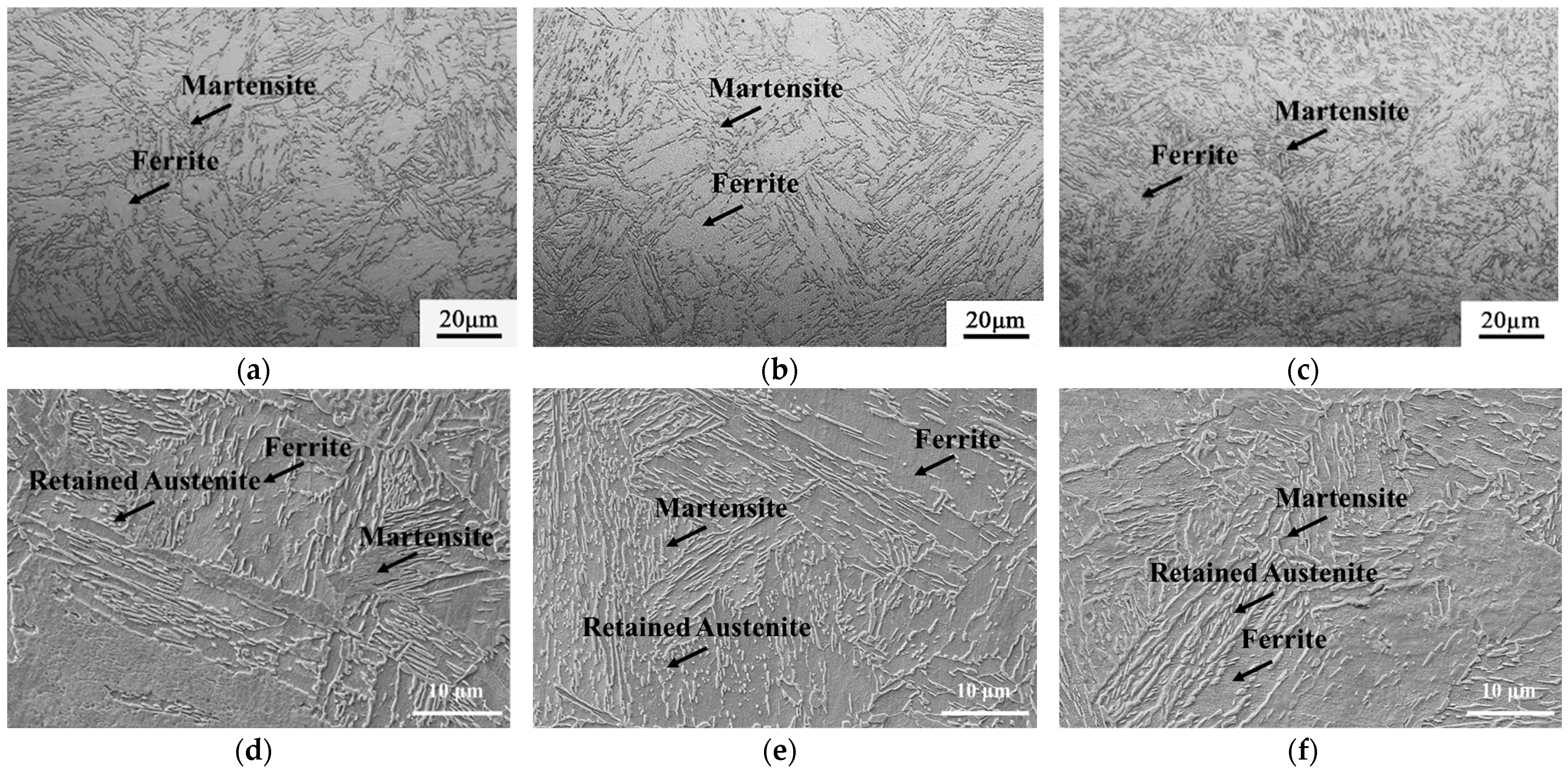
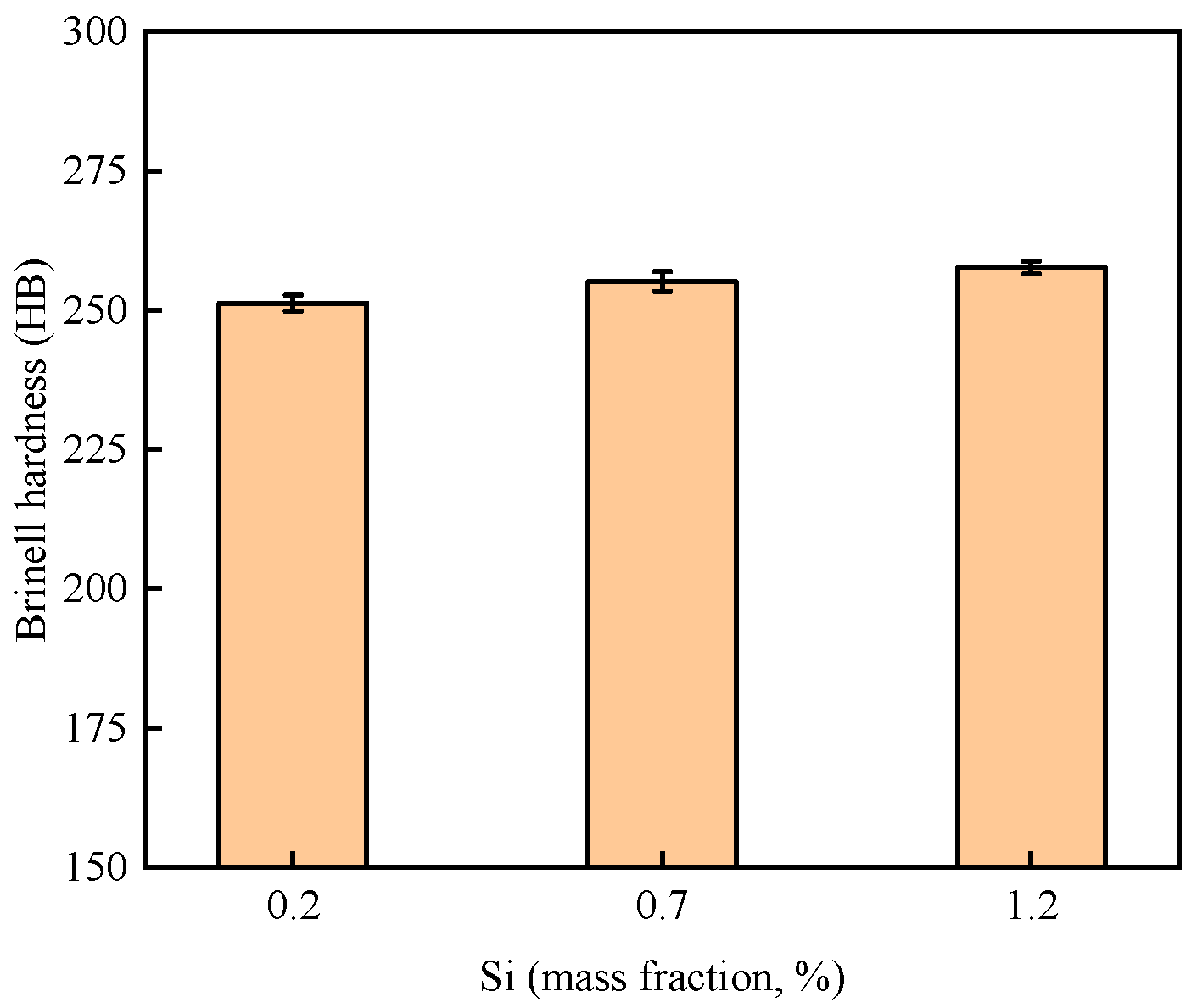
3.2. Microstructure and Hardness of Test Steel after Two-Step Heat Treatment

Figure 5 shows the microstructure of the experimental steel after quenching at 900 °C and intercritical quenching at 720 °C. In Figure 5, the microstructure of steel with different Si contents after the two-step heat treatment is mainly composed of ferrite and martensite. With the increase in Si content, the ferrite content in the microstructure decreases, and the ferrite and martensite structures become finer and more evenly distributed, which is conducive to improving the hardness and strength of the steel. In Figure 6, the average values of the Brinell hardness of the tested steel after two steps of heat treatment are 251 HB, 255 HB, and 257 HB, indicating an increase in hardness. In the process of two-phase zone quenching, a reverse transformation austenite structure is formed at the original austenite grain boundary and between lath martensitic and along with the gradual enrichment of austenite-stabilizing elements C and Mn into the reverse transformation austenite, which leads to the improvement in the stability of austenite. In the subsequent cooling process, part of this reverse transformation austenite is transformed into bainite–martensite, and the other part can still stably exist to form a small amount of retained austenite [26].

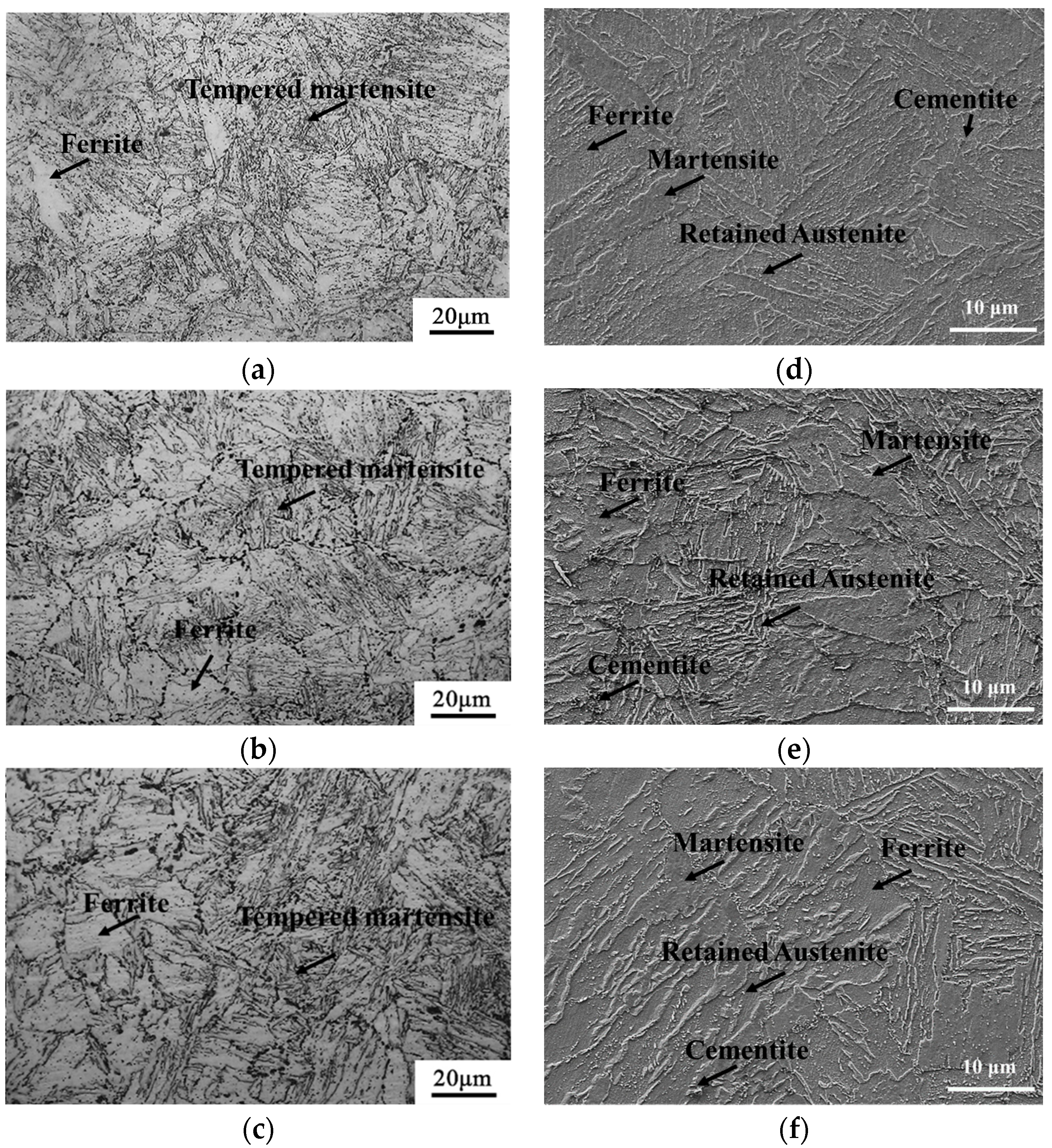
3.3. Microstructure and Mechanical Properties of Test Steel after Intercritical Tempering Treatment

Figure 7 shows the microstructure of the experimental steel after quenching at 900 °C + intercritical quenching at 720 °C + and intercritical tempering at 680 °C. The microstructure of the steel after three-step heat treatment is mainly composed of a dual-phase structure of ferrite and tempered martensite, with a small amount of retained austenite. With the increase in Si content, the boundary of ferrite and tempered martensite becomes clear, and the ferrite matrix has no obvious change. The structure of tempered lath martensite becomes clear with the increase in Si content, and compared with the microstructure after intercritical quenching, the boundary of ferrite and tempered martensite becomes clearer. A large number of dispersed lamellar and fine granular structures can be observed at the ferrite grain boundary or within the grain. These fine particles are mainly cementite formed after high-temperature tempering and finally stable retained austenite [12].
Figure 8 shows the engineering stress–strain curves of samples with different Si contents after three-step heat treatment, and their corresponding mechanical properties are shown in Table 3. Combining Figure 8 and Table 3, the tensile curves of the tested steel after three-step heat treatment are all continuous yield, without an obvious yield plateau, indicating that the plastic deformation of the tested steel mainly occurs during the entire tensile stage, rather than at a specific yield point. As the Si content increases, the tensile strength and hardness gradually increase, the average values of the Brinell hardness are 214 HB, 227 HB, and 234 HB in Figure 9. When the Si content is 1.206 wt. %, the tensile strength is the highest, and the elongation ratio first increases and then decreases. When the Si content is 0.685 wt. %, the elongation is the best.
The tensile strength of steel 0.2 Si is 652 MPa, the yield strength is 480 MPa, the elongation is 28.4%, the yield ratio is 0.74, and the strength–plasticity product reaches 18,517 MPa·%. The tensile strength of steel 0.7 Si is 726 MPa, the yield strength is 474 MPa, the elongation is 30.5%, the yield ratio is 0.65, and the strength–plasticity product reaches 22,143 MPa·%. The tensile strength of steel 1.2 Si is 760 MPa, the yield strength is 499 MPa, the elongation is 26.8%, the yield ratio is 0.66, and the strength–plasticity product reaches 20,368 MPa·%. As shown in Table 3, the tensile strength and hardness of the tested steel increase with the increase in Si content, while the elongation first increases and then decreases with the increase in Si content, and the addition of Si can reduce the yield ratio.
The continuous improvement in tensile strength is affected by two aspects. On the one hand, the solid solution of Si in ferrite plays a role in solid solution strengthening, which increases the strength and hardness of steel [27]. On the other hand, with the increase in Si content, the size of martensite in the test steel becomes finer, and the distribution becomes more uniform, which increases the effective grain boundary area of ferrite and martensite, increases the resistance to dislocation movement, and increases the shear stress required for deformation [28]. Therefore, the tensile strength and hardness of the test steel continue to improve. Generally speaking, the higher the strength and hardness of steel, the worse its elongation [29]. However, the elongation of the test steel first increases and then decreases because Si inhibits the formation of carbides, allowing carbon to diffuse from martensite to austenite. The enrichment of carbon in the original austenite is more complete, the stability is improved, and more retained austenite at room temperature is formed, which promotes the formation of retained austenite. During the plastic deformation process, due to the TRIP effect of retained austenite, the retained austenite undergoes a gradual martensitic transformation. This transformation process simultaneously enhances ductility, eliminates stress concentration, and delays the occurrence of necking, resulting in an increase in the elongation of the steel. Therefore, when the Si content is increased to 0.685 wt. %, the elongation increases. However, when the Si content is too high, a large amount of retained austenite grains are encapsulated within the soft ferrite matrix, resulting in the inability of retained austenite to exert its TRIP effect under stress and making it difficult to achieve an increase in plasticity. Therefore, when the Si content is increased to 1.206 wt. %, the elongation of the test steel decreases.
When the Si content increases to 0.685 wt. % and 1.206 wt. %, the yield ratio of the test steel decreases from 0.74 to 0.65 and 0.64, respectively. This is due to the increase in Si content, which clarifies the boundary between ferrite and martensite tempered structures. As a strengthening phase, martensite induces a large number of mobile dislocations within the adjacent ferrite, which can be activated at lower stress levels. Therefore, the test steel with Si contents of 0.685 wt. % and 1.206 wt. % exhibits low yield ratio characteristics. The strength–ductility product is a key index for evaluating the comprehensive mechanical properties of steel, which can directly reflect the forming and impact resistance of steel [27]. When the Si content is 0.685 wt. %, the steel has the best strength–ductility product, indicating that the steel has the best comprehensive performance.

3.4. The Fracture Morphology of the Test Steel after Tempering

Figure 10 shows the micro-morphology of the tensile sample fracture at different Si contents. There are unevenly sized circular or elliptical dimples in the micro-morphology of each sample, indicating that each sample has a slow tearing process, which will consume a large amount of plastic deformation work during the deformation process. The samples with larger size and deeper dimples have better plasticity. As shown in Figure 10a,b, the micro-morphology of the fracture of the samples with Si contents of 0.18 wt. % and 0.685 wt. % shows large and deep dimples, and the fracture is dominated by dimples. Combined with Table 3, the elongation is higher, and the plasticity is better. However, the micro-morphology of the fracture of the sample with a Si content of 1.206 wt. % shows relatively few dimples, with more cleavage planes and tearing edges, as shown in Figure 10c, which indicates poor elongation.

4. Conclusions

  • The microstructure of the test steel after quenching at 900 °C and intercritical quenching at 720 °C is mainly composed of ferrite and martensite structures. As the Si content increases, the ferrite content in the microstructure decreases, and the ferrite and martensite structures become finer and more evenly distributed.
  • After quenching at 900 °C, intercritical quenching at 720 °C, and intercritical tempering at 680 °C, the microstructure of the steel is mainly composed of a dual-phase structure of ferrite and tempered martensite, with a small amount of retained austenite and cementite. With the increase in Si content, the boundary between ferrite and martensite becomes clear after tempering, and the structure of tempered lath martensite becomes clear gradually.
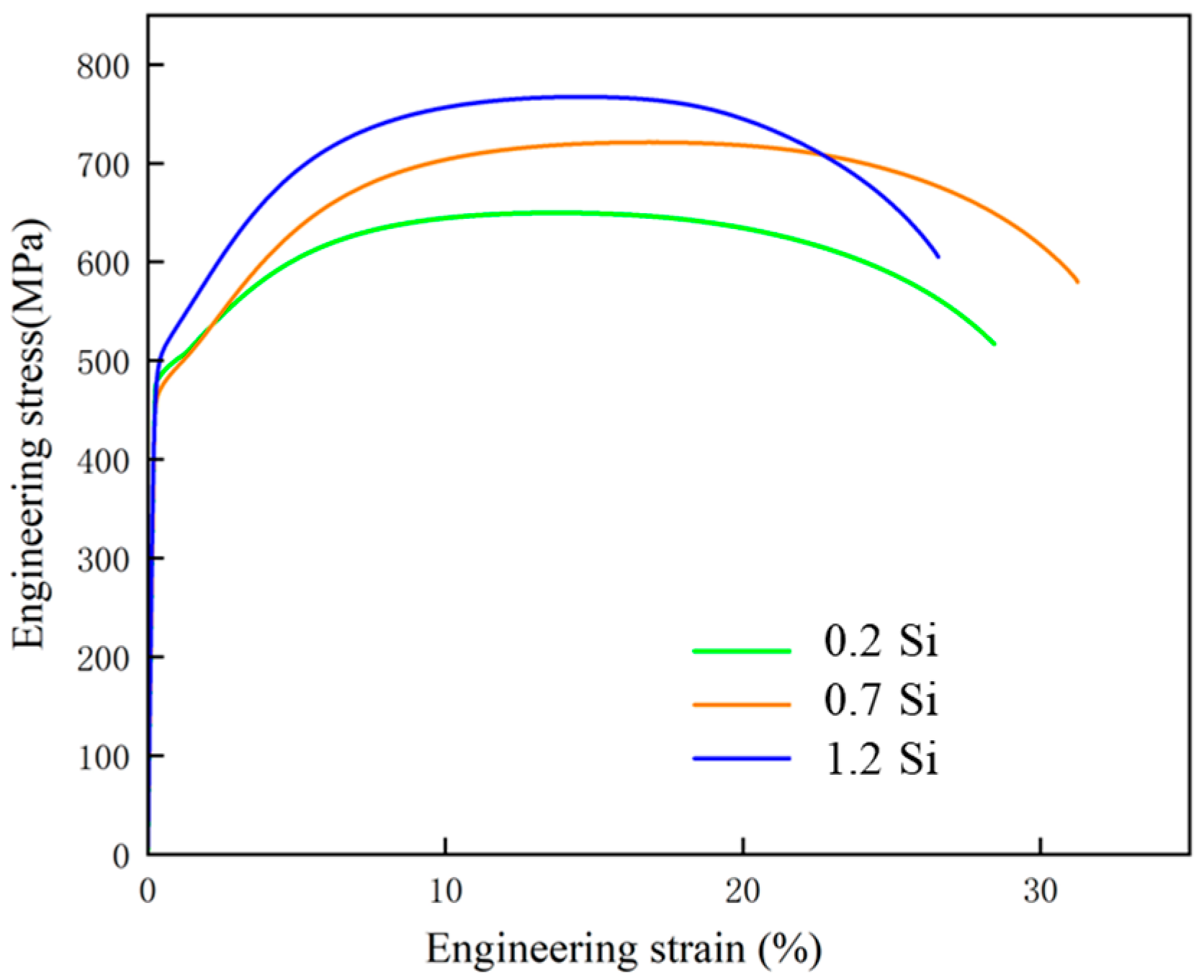
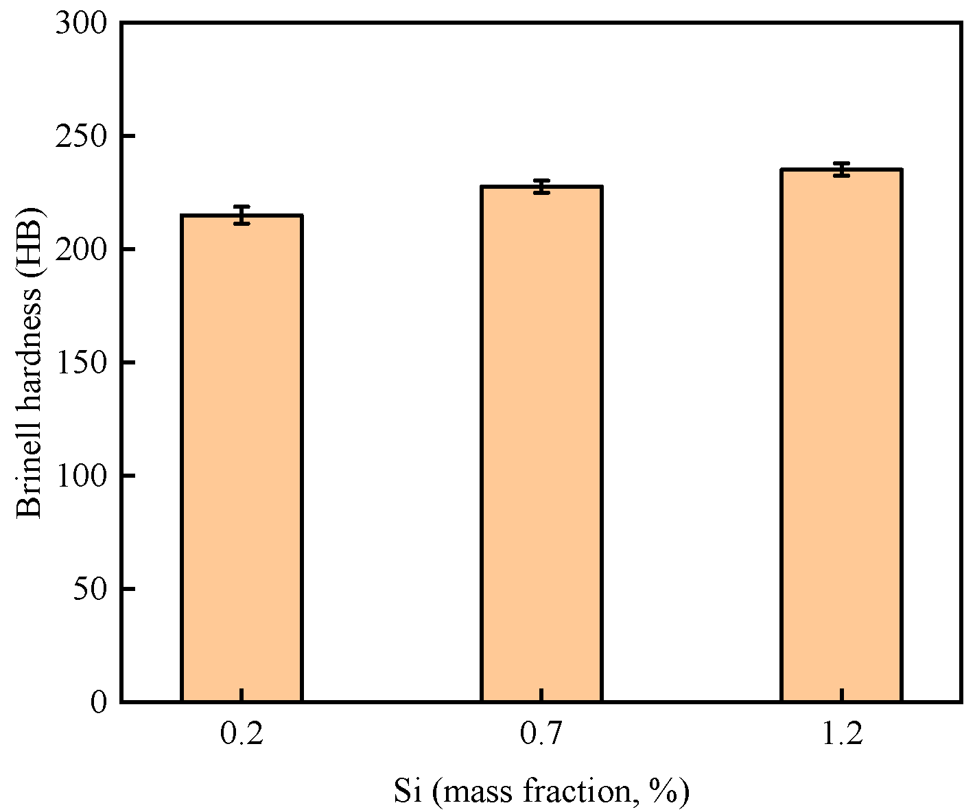
  • The increase in Si content gradually increases the tensile strength and hardness of the test steel, with a slight decrease in the yield ratio and an initial increase followed by a decrease in elongation. When the Si content is 0.685 wt. %, the comprehensive performance of the test steel is optimal, with a tensile strength of 726 MPa, a yield ratio of only 0.65, the highest elongation of 30.5%, and the highest strength–ductility product of 22,143 MPa·%.

Author Contributions

Z.H.: experimental design, data collection, data analysis, and manuscript writing; H.F.: first draft revision, project management, technical supervision, and manuscript writing. All authors have read and agreed to the published version of the manuscript.

Funding

The authors would like to thank the financial support for this work from Hebei Science and Technology Major Project (22281005Z).

Data Availability Statement

The raw data supporting the conclusions of this article will be made available by the authors on request.

Conflicts of Interest

The authors declare no conflict of interest.

References

  1. Weng, Y.Q.; Yang, C.F.; Shang, C.J. Development status and trend of low alloy steel in China. Steel 2011, 46, 1–10. [Google Scholar]
  2. Qiao, Y.; Wang, G. Recent Status of Production, Administration Policies, and Low-Carbon Technology Development of China’s Steel Industry. Metals 2024, 14, 480. [Google Scholar] [CrossRef]
  3. Gao, G.; Liu, R.; Wang, K.; Gui, X.; Misra, R.D.K.; Bai, B. Role of retained austenite with different morphologies on sub-surface fatigue crack initiation in advanced bainitic steels. Scr. Mater. 2020, 184, 12–18. [Google Scholar] [CrossRef]
  4. Xiao, H.; Zhao, G.; Xu, D.; Cheng, Y.; Bao, S. Effect of Microstructure Morphology of Q&P Steel on Carbon and Manganese Partitioning and Stability of Retained Austenite. Metals 2022, 12, 1613. [Google Scholar] [CrossRef]
  5. Wu, Z.X.; Chen, X.; Liu, Y.; Li, Y.X.; Zhang, H.W. Effect of intercritical tempering treatment on the microstructure and mechanical properties of high-alloy cast steel. Foundry 2022, 70, 1156–1161. [Google Scholar]
  6. Miller, R.L. Ultrafine-grained microstructures and mechanical properties of alloy steels. Met. Trans. 1972, 3, 905–912. [Google Scholar] [CrossRef]
  7. Niikura, M.; Morris, J.W. Thermal processing of ferritic 5Mn steel for toughness at cryogenic temperatures. Met. Trans. A 1980, 11, 1531–1540. [Google Scholar] [CrossRef]
  8. Lee, Y.-K.; Han, J. Current opinion in medium manganese steel. Mater. Sci. Technol. 2015, 31, 843–856. [Google Scholar] [CrossRef]
  9. Xie, Z.-J.; Shang, C.-J.; Wang, X.-M.; Han, G.; Misra, R.-D. Recent progress in third-generation low alloy steels developed under M3 microstructure control. Int. J. Miner. Met. Mater. 2020, 27, 1–9. [Google Scholar] [CrossRef]
  10. Xi, X.; Wang, J.; Chen, L.; Wang, Z. Tailoring Mechanical Properties of a Low Carbon Cu-Containing Structural Steel by Two-Step Interintercritical Heat Treatment. Met. Mater. Int. 2019, 25, 1477–1487. [Google Scholar] [CrossRef]
  11. Huang, L.; Deng, W.T.; Liu, J.; Wang, Z. Relationship between retained austenite stability and low-temperature toughness in 0.12C-3.0Mn low-carbon medium-manganese steel. J. Met. 2017, 53, 316–324. [Google Scholar]
  12. Li, D.J.; Bai, Q.; Chen, J.J.; Lv, N.; Feng, Y.R.; Ren, F.Z. Effect of intercritical heat treatment on the microstructure and mechanical properties of low-alloy TRIP steel. J. Mater. Heat Treat. 2019, 40, 111–117. [Google Scholar]
  13. Liu, L.; He, B.; Huang, M. The role of transformation-induced plasticity in the development of advanced high strength steels. Adv. Eng. Mater. 2018, 20, 1701083. [Google Scholar] [CrossRef]
  14. Sun, B.; Fazeli, F.; Scott, C.; Guo, B.; Aranas, C., Jr.; Chu, X.; Jahazi, M.; Yue, S. Microstructural characteristics and tensile behavior of medium manganese steels with different manganese additions. Mater. Sci. Eng. A 2018, 729, 496–507. [Google Scholar] [CrossRef]
  15. Li, Z.C.; Misra, R.D.K.; Cai, Z.H.; Li, H.X.; Ding, H. Mechanical properties and deformation behavior in hot-rolled 0.2 C-1.5/3Al-8.5 Mn-Fe TRIP steel: The discontinuous TRIP effect. Mater. Sci. Eng. A 2016, 673, 63–72. [Google Scholar] [CrossRef]
  16. Cai, Z.H.; Wang, S.K.; Zhou, Y.J.; Li, Z.C. The synergistic effect of grain refinement and precipitation strengthening on mechanical properties and dry sliding wear behavior of medium manganese steels. Tribol. Int. 2023, 179, 108158. [Google Scholar] [CrossRef]
  17. Zhang, B.G.; Zhang, X.M.; Liu, H.T. Microstructural evolution and mechanical properties of Ni-containing light-weight medium-Mn TRIP steel processed by intercritical annealing. Mater. Sci. Eng. A 2020, 793, 139289. [Google Scholar] [CrossRef]
  18. Zhang, S.; Zhou, W.; Hu, F.; Yershov, S.; Wu, K. The role of Si in enhancing the stability of residual austenite and mechanical properties of a medium carbon bainitic steel. J. Mater. Res. Technol. 2024, 30, 1939–1949. [Google Scholar] [CrossRef]
  19. Kim, B.; Sietsma, J.; Santofimia, M.J. The role of silicon in carbon partitioning processes in martensite/austenite microstructures. Mater. Des. 2017, 127, 336–345. [Google Scholar] [CrossRef]
  20. Hwang, S.; Bai, Y.; Gao, S.; Park, M.-H.; Shibata, A.; Tsuji, N. Mechanism of simultaneous increase of strength and ductility with grain refinement in Si-added high-Mn austenitic steel. Mater. Sci. Eng. A 2024, 894, 146193. [Google Scholar] [CrossRef]
  21. Song, C.; Zhang, Z.; Wu, W.; Wang, H.; Sun, Z.; Yang, Y.; He, W.; Xu, J.; Xia, Y.; Yin, W.; et al. Effect of Si on the dislocation state within martensite of ultra-high strength hot-rolled medium Mn steel with good ductility. Mater. Sci. Eng. A 2023, 869, 144825. [Google Scholar] [CrossRef]
  22. Nouri, A.; Saghafian, H.; Kheirandish, S. Effects of Si Content and Interintercritical Annealing on Manganese Partitioning in Dual Phase Steels. J. Iron Steel Res. 2010, 17, 44–50. [Google Scholar] [CrossRef]
  23. Zhu, Z.F.; Zhao, Z.Z.; Zhao, A.M.; Tang, D. Effect of Si on the microstructure and properties of high-strength hot-rolled duplex steel. Roll. Steel 2011, 28, 16–18. [Google Scholar]
  24. GB/T 228.1-2021; Metallic Materials-Tensile Testing—Part 1: Method of Test at Room Temperature. China Standards Publishing House: Beijing, China, 2021.
  25. GB/T 231.1-2018; Metallic Materials-Brinell Hardness Test—Part 1: Test Method. China Standards Publishing House: Beijing, China, 2018.
  26. Xie, Z.J.; Yuan, S.F.; Zhou, W.H.; Yang, J.R. Stabilization of retained austenite by the two-step interintercritical heat treatment and its effect on the toughness of a low alloyed steel. Mater. Des. 2014, 59, 193–198. [Google Scholar] [CrossRef]
  27. Xu, Y.; Cao, W.; Huang, M.; Zhang, F. First Principles Study of the Effects of Si, P, and S on the ∑5 (210)[001] Grain Boundary of γ-Fe. Metals 2024, 14, 471. [Google Scholar] [CrossRef]
  28. Shi, N.; Liu, W.M.; Liu, Y.G.; Zhan, H.; Cui, L.; Pan, H.B. Effects of Si content and quenching temperature on the microstructure and properties of Q&P steel. Met. Heat Treat. 2022, 47, 130–135. [Google Scholar] [CrossRef]
  29. Shin, S.-H.; Oh, D.-K.; Hwang, B. Influence of Heat Treatment on Microstructure and Mechanical Properties of Direct-Quenched Fe-0.06C-0.2Si-2.0Mn Steel. Metals 2023, 13, 1912. [Google Scholar] [CrossRef]
Figure 1. CCT curves of steel tested with different Si contents: (a) 0.2 Si; (b) 0.7 Si; (c) 1.2 Si.
Metals 14 00675 g001
Figure 2. Schematic diagram of heat treatment process of tested steel.
Metals 14 00675 g002
Figure 3. Microstructure of test steel forged plate: (a) 0.2 Si; (b) 0.7 Si; (c) 1.2 Si.
Metals 14 00675 g003
Figure 4. Brinell hardness of test steel forged plate.
Metals 14 00675 g004
Figure 5. The metallographic microstructure and SEM morphology of the test steel with different Si contents under the annealing process: (a,d) 0.2 Si; (b,e) 0.7 Si; (c,f) 1.2 Si. (ac) OM; (df) SEM.
Metals 14 00675 g005
Figure 6. The Brinell hardness of the test steel with different Si contents under the annealing process.
Metals 14 00675 g006
Figure 7. The metallographic microstructure and SEM morphology of the test steel with different Si contents under the tempering process: (a,d) 0.2 Si; (b,e) 0.7 Si; (c,f) 1.2 Si. (ac) OM; (df) SEM.
Metals 14 00675 g007
Figure 8. Stress–strain curve.
Metals 14 00675 g008
Figure 9. The Brinell hardness of the test steel with different Si contents under the tempering process.
Metals 14 00675 g009
Figure 10. Fracture morphology of different Si content test steel after heat treatment: (a) 0.2 Si; (b) 0.7 Si; (c) 1.2 Si.
Metals 14 00675 g010
Table 1. The chemical composition of the tested steel (wt. %).
SampleCSiMnPSFe
0.2 Si0.1070.1803.0100.0080.009Bal.
0.7 Si0.1110.6853.1740.0080.009Bal.
1.2 Si0.1101.2063.1540.0080.009Bal.
Table 2. Transformation temperature of experimental steel.
SampleAc3 (°C)Ac1 (°C)Ms (°C)Mf (°C)
0.2 Si778.4657.2368254.3
0.7 Si792.1665.2359.6245.2
1.2 Si807.6673.5357.5244.2
Table 3. Tensile properties of test steels after intercritical thermal treatment.
SampleYS (MPa)TS (MPa)Y/T RatioTEL (%)PSE (MPa·%)Hardness (HB)
0.2 Si480 ± 7652 ± 30.7428.4 ± 0.318,517214
0.7 Si474 ± 8726 ± 50.6530.5 ± 0.222,143227
1.2 Si499 ±10760 ± 80.6626.8 ± 0.220,368234
Disclaimer/Publisher’s Note: The statements, opinions and data contained in all publications are solely those of the individual author(s) and contributor(s) and not of MDPI and/or the editor(s). MDPI and/or the editor(s) disclaim responsibility for any injury to people or property resulting from any ideas, methods, instructions or products referred to in the content.

