
Clinching of Carbon Fiber-Reinforced Composite and Aluminum Alloy


Institute of Forming Technology and Equipment, Shanghai Jiao Tong University, Shanghai 200030, China
*
Author to whom correspondence should be addressed.
Metals 2024, 14(6), 681; https://doi.org/10.3390/met14060681
Submission received: 28 April 2024
/
Revised: 23 May 2024
/
Accepted: 24 May 2024
/
Published: 8 June 2024
(This article belongs to the Special Issue Advanced Welding and Joining Processes for Automotive Applications)
Abstract
:The extensive use of carbon fiber-reinforced composites and aluminum alloys represents the highest level of automotive body-in-white lightweighting. The effective and secure joining of these heterogeneous materials remains a prominent and actively researched topic within the scientific community. Among various joining techniques, clinching has emerged as a particularly cost-effective solution, experiencing significant advancements. However, the application of clinching is severely limited by the properties of the joining materials. In this work, various clinching processes for the joining of composites and aluminum alloys reported in recent research are described in detail according to three broad categories based on the principle of technological improvement. By scrutinizing current clinching technologies, a forward-looking perspective is presented for the future evolution of clinching technology in terms of composite–aluminum joints, encompassing aspects of tool design, process analysis, and the enhancement of joint quality. This work provides an overview of current research on clinching of CFRP and aluminum and serves as a reference for the further development of clinching processes.
1. Introduction
Carbon fiber-reinforced polymers (CFRPs) have historically been highly favored lightweight materials in the automotive industry [1,2,3,4,5]. Offering excellent mechanical properties at a comparatively low weight compared to traditional metals [6,7,8], CFRP has played a pivotal role in reducing the weight of automobiles, subsequently lowering greenhouse gas emissions and fossil energy consumption [9]. In recent years, with the evolution of electric vehicles and urban air mobility, the demand for extended range and heightened safety has led to an increased application of CFRPs in battery enclosure systems for efficient energy storage [10,11].
Simultaneously, aluminum alloys, recognized for their efficiency as lightweight materials, have gained prominence in the aerospace [12] and automotive sectors [13] due to their balanced strength, controllable ductility, and remarkable corrosion resistance [14]. In current mainstream electric vehicle battery enclosure systems, nearly 60% of the frame components are made of aluminum alloy material, showcasing the growing adoption of overall aluminum alloy designs. Notably, aluminum battery enclosures and platform components can achieve up to a 40% reduction in weight compared to their steel counterparts [15].
To further advance lightweighting efforts, the mid-range and high-end electric vehicle sectors are increasingly embracing hybrid material design solutions that incorporate both aluminum alloys and composite materials [16]. Consequently, the secure and reliable joining of components made from different materials during the assembly process significantly influences the final product’s quality [17]. Presently, joining techniques can be broadly classified into the following four main groups: mechanical joining, adhesive bonding, welding, and hybrid joining. Mechanical joining, also known as joining by forming, is predominantly achieved through the deformation of the materials being joined and the use of auxiliary elements [18]. Hahn and Klemens suggested categorizing mechanical joining based on the presence or absence of an auxiliary element, pre-hole, and material cutting [19]. The evolution of mechanical joining has significantly expanded the scope of joining dissimilar materials, finding extensive applications in the automotive [20], aviation, and white goods [21,22] sectors. Adhesive bonding involves combining two or more components through the use of an adhesive [23]. To ensure uniform wetting of the entire surface and prevent droplets, the surface tension of the selected adhesive must be lower than that of the material being bonded [24]. Attaining the final bonding strength requires allowing the adhesive sufficient time to cure, and the surface of the joined material should undergo suitable pretreatment (i.e., surface activation and roughness profile) [25]. Being one of the oldest joining technologies, welding is frequently employed for metals [26] or thermoplastics [27,28]. This process primarily involves the melting of materials at high temperatures, allowing them to diffuse into each other and form a cohesive component upon cooling [29]. Currently, various welding technologies are applicable to sheet and profile materials [30], including arc welding [31], beam welding [32], friction stir welding [33], resistance welding [34], and more. The advantages of welding lie in its mature processes, cost-effectiveness, and broad applicability [35]. However, the unavoidable thermal effects generated by heating in non-welding areas [36] may lead to unnecessary material deformation [37] and damage [38]. To achieve enhanced mechanical performance in joints or to meet more demanding joining requirements, a combination of two or more joining techniques, known as hybrid joining, can be employed [19]. For instance, spot mechanical joining can be combined with adhesive bonding. This allows the mechanical joining to provide stability to the parts being joined during the adhesive curing process [39]. Additionally, combining welding with mechanical joining enables fasteners to penetrate materials that cannot be welded, and the final strength of the joint is achieved by welding the fasteners to the part [34]. However, it is important to note that hybrid joining entails more complex joining processes and higher associated costs [40,41].
A vast body of literature provides various solutions for the joining of plate-shaped carbon fiber-reinforced polymer and aluminum alloy. Common joining techniques encompass adhesive bonding, diffusion bonding [42], self-piercing riveting [43], bolting, welding [44], clinching, embedding of inserts [45], flow drill screwing [46], flow drill riveting [47], and friction stir blind riveting [48].
Of these, clinching stands out as the most cost-effective joining technology for sheet and profile materials due to its ability to save fasteners, eliminate the need for surface pretreatment, and avoid thermal influence [19]. While various studies have explored the clinching of CFRP and aluminum alloy, comprehensive and systematic classification and analysis of these studies are notably absent. The main objective of this work is to compare and analyze existing spot-clinching techniques from the perspective of the fundamental mechanisms employed to achieve the joint, summarizing the advantages and disadvantages of different clinching methods. This study aims to delineate future research directions in this field. In doing so, it seeks to facilitate the selection of suitable joining process in industry, offering a theoretical foundation and providing research insights for future technological innovations.
2. Clinching
2.1. Fundamentals of Clinching
According to DIN 8593-5 [18], clinching falls under the category of “joining by forming”. This entails the process of joining two or more overlapping sheet-metal, tube, and/or profile parts through cold forming, employing a punch and die. By clinching, a form and force fitting are created, in which no additives or auxiliary materials are used [49]. A typical clinching process involves the following steps:
- -
- Securing the joining partners using a blank holder;
- -
- Partial penetration of the joining partners;
- -
- Partial displacement of the joining partners from the initial plane;
- -
- Subsequent upsetting;
- -
- Formation of an inseparable joint through spreading or extrusion.
Regarding tool kinematics, clinching is categorized into single-stage and two-stage clinching [50,51]. In the single-stage clinching process, only one drive is applied by the punch or die. Typically, a round clinch joint is formed through a continuous setting process using a rigid die (Figure 1a), an opening die (Figure 1b), or a flat die (Figure 1c), where the joining partners are not cut. Alternatively, a rectangular punch is commonly employed to create a non-twisting clinch joint (Figure 1d), in which case the joining partners are cut and locally widened. In the two-stage clinching process, both the punch and the die are actively driven, enabling two distinct joining processes. Typically, during the first process, the joining partners are either locally pushed or cut out from the initial sheet plane. Subsequently, the undercut is formed using an upsetting punch [19].
Irrespective of the clinching variant, a certain level of plastic deformation of the joined materials is essential. According to DVS/EFB 3420, materials suitable for clinching should have a tensile strength of TS ≤ 300 MPa, a yield or proof stress ratio of YS/TS ≤ 0.7, and an elongation at break of UE ≥ 12 [49]. If the material properties fall outside this range, specific optimizations are necessary during clinching. Examining the geometrical characteristics of a clinch joint, the neck thickness, undercut, and work hardening of the materials being joined have the most significant influences on joint strength (Figure 2) [20,52]. During the clinching process, the metallic material is elongated vertically in the neck area and drawn horizontally in the bottom area (Figure 3) [53]. No visible microstructural change can be detected in the joining partner after clinching [39].
2.2. Imperfection of Clinching CFRP and Aluminum
Common composites are currently classified into the following two main categories based on fiber length: short fibers and long fibers. Short fibers typically range from 1 to 10 mm, while long fibers generally exceed 25 mm [54]. Behrens et al. demonstrated the viability of clinching resin-based short fiber composites at room temperature, achieving maximum mechanical occlusion with a fiber content of 30% [55]. In practice, composites with long fibers are more prevalent due to their superior mechanical properties [56]. In the preparation of composites, long fibers are typically woven in different patterns to attain specific mechanical properties. However, unlike short-fiber composites, the anisotropy of long-fiber materials and their limited plastic deformation ability pose challenges in achieving significant plastic deformation at room temperature [57]. Consequently, clinching long-fiber composites with a high degree of plastic deformation remains a challenging task. Lambiase and Ko explored the feasibility of the clinching process for the joining of AA6082 T6 (thickness of 2.0 mm) and CFRP (thickness of 1.4 mm). The study revealed that while joint quality can be improved to some extent by selecting an appropriate clinching tool, the irregular fracture of the composite material at the clinch points due to squeezing and the resultant damage around the joint cannot be entirely avoided (Figure 4) [58]. In contrast to the clinching of pure metal materials to form a closed bottom area, the material flow differs when joining metals to composites [59]. Lambiase et al. highlighted that the local penetration of the joining partners initiates damage in the CFRP, positioned on the die side. The composite material cannot undergo the same level of deformation as the punch-sided aluminum alloy, reaching the die anvil, due to its limited plastic deformation capacity. Instead, initial material damage may occur in the region subjected to pressure (Figure 5a). During upsetting formation, bottom crumbles occur in the already damaged composite part. In the region where the bottom meets the neck, a new contact surface is created due to the combination of positive pressure and shear forces, leading to the detachment of a slug from the bottom area (Figure 5b). In the final spreading section, the aluminum alloy is pressed radially outwards as the bottom thickness decreases. Consequently, the composite material undergoes radial compression, generating more crumbles on one hand and, on the other hand, causing additional damage around the joint due to increased pressure (Figure 5c) [59].
Han et al. observed the formation of a conical slug when a composite material underwent shear stress in the thickness direction. Consequently, when punching composite materials, a hole with a wide top and narrow bottom was created [60]. This particular phenomenon can lead to curling of the composite material when clinching metals and composites, especially during the spreading phase, thereby causing additional material damage (Figure 6) [58]. Due to these inherent defects, the conventional clinching of CFRP and aluminum at room temperature has not found practical application. Nevertheless, various new clinching processes have emerged from the traditional method. In all cases, the goal is to minimize damage to the composite material during the joining process and create a more stable joint with improved mechanical properties.
3. Advanced Clinching Methods
To overcome the previously mentioned deficiency and, moreover, to enhance the joint quality of clinched CFRP and aluminum alloys, getting over the limited plasticity of the composite material is essential. Simultaneously, promoting the plastic deformation of the metal material is crucial to achieve more effective mechanical occlusion with the composite material. Summarizing current research, the methods for optimizing the quality of clinched composite and aluminum alloy joints can be broadly categorized into three distinct groups, as illustrated in Figure 7. Modification of the material structure is mainly for the composite material. Common processing methods include prefabricating through-holes in the cured composite sheet and pre-forming the composite prepreg prior to curing. Modifying the properties of the clinched materials is mainly done through auxiliary heating. Heating can be achieved by direct contact with the composite material or indirectly by generating heat through friction between the tool and the joined metal component. To increase the efficiency of the heating process, it is also possible to use a laser to heat the joined component. Another approach involves combining both the structural and material properties to address specific joining requirements. In the following chapters, the optimization of the clinching process based on current studies will be described in detail.
3.1. Modification of the Material Structure
Lee et al. presented a solution for clinching aluminum alloy AA 6061 (t = 2.4 mm) and CFRP (t = 1.6 mm) with a pre-hole. Using a punch diameter of 7.2 mm, a through-hole with a diameter of 8.2 mm was prepared in the composite part. A rigid die with a depth of Dp = 1.0 mm was employed for joining (Figure 8a). Throughout the setting process, it was observed that the aluminum sheet was initially pushed during setting of the punch. No deformation of the CFRP was detected until full contact between the penetrated aluminum and the CFRP was achieved. However, radial material flow in the neck and bottom area of the clinch joint resulted in the expansion of the hole in the CFRP when spreading the aluminum (Figure 8c). This process phase was evidenced by a stiffer increase in force (Figure 8b). The radial material flow of the aluminum led to the formation of the undercut, while dragging the CFRP resulted in material delamination, as shown in Figure 8d. This material damage can significantly impair the shear tensile strength of the clinch joint. To reduce delamination, a larger punch radius (R) can be used. Additionally, the shape of the punch corner has a major influence on the formation of the clinch joint. Using a blunt punch corner can prevent neck fracture but leads to a more expanded hole. However, the expansion of the hole results in a smaller undercut due to the lack of formed material [61].
To achieve the optimal deformation behavior of joint parts, a compromise should be chosen. As depicted in Figure 9, an increase in punch radius ® from 0.3 mm to 0.7 mm results in elevated neck thickness and hole expansion, accompanied by a reduction in undercut. At a punch radius of R = 0.3 mm, neck fracture is observable, irrespective of die depth. With an increase in die depth (Dp), both undercut and hole expansion rise, while the neck area becomes thinner. Since the clinch joint’s load-bearing capacity is predominantly influenced by neck thickness [62], the optimal tool configuration, balancing form fit, and CFRP damage are identified as a punch radius of R = 0.5 mm with a die depth of Dp = 6.6 mm [63].
Liu et al. introduced a continuous damage model suitable for the numerical assessment of laminates during hole clinching, enabling the quantitative calculation of CFRP material damage in different fiber directions (Figure 10). The continuous damage model can be defined as follows [64]:
where dij represents the damage variables with different fiber directions, and and represent the strain and stress tensors, respectively. The modified Hashin failure criterion is applied to simulate fiber and matrix fractures, while the Linde failure criterion can estimate the delamination of composite material due to the joining process [65]. The initial failure strain in varied failure mode can be defined as follows [65]:
where represents the initial tensile, compressive, and shear failure strains according to the fiber direction, and , , , and are the tensile, compressive, and shear strength in the principal directions. To depict the damage evolution, a bilinear constitutive law controlled by an intermediate damage variable can be utilized. The law is defined by the intermediate damage variables () [65]:
where is the ultimate failure strain, is the energy release rate, and represents the characteristic length of an element. The study reported in [64] indicated that matrix tension and fiber–matrix shear damage dominate in [0°/90°] CFRP and [45°/−45°] CFRP. In most clinched [45°/90°/−45°/0°/90°/45°] CFRP configurations, delamination is observed.
An additional strategy to enhance joint quality during clinching with a pre-hole involves employing a spring die, comprising a hollow, cylindrical formed die and a spring-loaded anvil [66,67]. The anvil is tailored to match the hole size of the composite material and is positioned above the die, allowing the die-sided joining partner to be aligned by the anvil prior to the clinching process. The joining partner on the punch side rests on the anvil from the outset. Throughout the clinching process, a hydrostatic compressive stress is applied to the metal part being clinched (Figure 11a). Particularly noteworthy is the neck area of the clinch joint, where tensile stress prevails during the setting process. Here, the use of a spring die facilitates significant stress equalization. This phenomenon acts as a preventive measure against neck breakage during clinching. Moreover, thinning of the clinch joint’s bottom, occurring early in the setting process when employing a spring die (Figure 11b), leads to reduced radial material flow during spreading. Consequently, the compressive stress on the hole wall of the composite part is diminished with a spring die, resulting in a substantial reduction in fiber and matrix breakage, as well as delamination (Figure 12). In essence, clinching with a pre-hole necessitates hole preparation and the alignment of joining partners, introducing additional production steps. The more intricate joining process also results in more challenging process control and quality assurance [68]. Lee et al. demonstrated that asymmetry between the punch and the pre-hole can induce significant variability in the maximum shear tensile strength and the failure modes of the joints [69].
As composite material can exhibit good formability before curing, the prepreg of the composite material can be joined to the aluminum using a modified forming and cutting process. Loterre et al. demonstrated that a prepreg of CFRP (t = 0.65 mm) placed on the punch side can be joined with an AA5754 aluminum sheet (t = 1.5 mm) on the die side using a punch and a die. The aluminum sheet is shear-cut, while the composite material is formed into the hole, creating an undercut. After curing, a gap-free clinch joint is formed (Figure 13b). The forming process does not break the carbon fibers, resulting in no visible loss of load-bearing capacity of the composite material. The overall joining process is divided into the elastic and plastic deformation of the joining partners (I, Figure 13a), cutting of the aluminum (IIa, Figure 13a), deformation of the prepreg (IIb, Figure 13a), and completion of the joint (III, Figure 13a). The formation of the undercut is facilitated by the angle of breakage in the aluminum after punching, allowing the prepreg to flow into the hole, creating a form fit. It has been proven that this type of shearing of the aluminum has no influence on the joint’s load-bearing capacity and is carried out after the composite material has been cured. Compared to other joining technologies, in terms of joint strength calculated by the shear force and overlapping area, joining by pre-punching with 5 MPa is clearly superior to bonding (3 MPa) and most mechanical joining processes and at a comparable level to hole clinching (Figure 13c) [70]. Regarding the joining process, it should be noted that this method only works before the composite material is cured, which can significantly limit the application of the joining process. Additionally, the deformation of the joined components is undefined, considering the influence of heat during the curing of the composite material.
3.2. Modification of the Material Property
The reliable clinching of hardened composite material with a metal sheet is an intriguing topic for practical applications. Lin et al. observed a significant softening of thermoplastic CFRP at 85 °C. Notably, effective clinching of a composite plate with aluminum alloy was observed starting from 100 °C [71]. Vorderbrüggen et al. introduced a heat-assisted clinching process (Hot clinch) to enhance the creation of a form fit during the setting process. The key process modification involves using a heatable rigid die with a spring-loaded anvil. Unlike a conventional spring-loaded die, the used die does not spread open during upsetting. The use of a spring-loaded anvil aims to achieve better material extrusion. It was observed that the sinking of the anvil, the heating temperature, and the punch diameter significantly influenced the formation of the undercut. A cartridge heater was directly integrated into the die holder, allowing the composite material to be indirectly heated to 180 °C after approximately 30 s. Heating can improve the flowability of the matrix material and reduces fiber breakage (Figure 14a,b). In addition, tool optimization can enhance the maximum tensile strength of the joint by up to 250%. The use of heat support brings an additional 20% improvement in performance [72]. In principle, the deformation of the composite material during clinching is determined by the yarn–yarn interaction. The aggregate state of the matrix can also influence the deformation and failure behavior of the composite material. Therefore, when modeling the clinching of CFRP with metal material, considerations should include fiber reorientation, fiber displacement, and the heterogeneous distribution of fibers and matrix [73].
Currently, there are four methods for heating the joining partners during clinching. In addition to direct contact heating [74], as previously explained, inductive heating (Figure 15a) is a viable option as well. Yarcu et al. employed an 18 kW inductor on the die side of the TOX® clinching system, achieving a temperature of 220 °C in 5.5 s for a 3 mm thick AlSi9Mn aluminum casting. This approach effectively prevents cracks in the closing head, resulting in a 25% increase in the maximum shear tensile force [75]. For rapid heating within seconds during clinching, a laser-assisted joining system can be utilized. Matzke introduced the TOX® THETA® clinching system, incorporating a laser beam into the punch-side tool (Figure 15b). Prior to punch positioning, an oblique laser beam is applied, heating the surface of the punch-side sheet metal to 700 °C in approximately 0.4 s. The reflected laser beam is efficiently removed from the joining zone within the blank holder [76]. Additionally, the joining partners can be heated through contact friction between the tool and the sheet metal. Lin and Lo developed a friction clinching process with regard to friction stir welding. This involves a rotating cylindrical punch that is electrically driven, generating frictional heat in the joining partner to soften it. It is important to note that effective heat generation through friction requires a metallic joining partner [77].
Generally, it should be emphasized that heat-assisted clinching is highly suitable for joining metal–FRP joints. By heating the composite material to above the glass transition temperature but below the melting point, the formability of the composite is significantly improved [78]. Despite the variety of heating methods, maintaining precise temperature control, especially during the joining process, poses a significant challenge in ensuring a reproducible joining process. As the joining system typically comprises different components, the complex heat flow dynamics and variations in thermal conductivity between the joining partners, the tool components, and the environment contribute to the intricacy of the process (Figure 16) [79]. In a continuous manufacturing process, where heat continuously accumulates in the system, defining the heat field becomes considerably more challenging.
3.3. Multi-Modification
Considering the limited options for altering the structure or properties of composite materials in most metal–FRP joints, the development of new clinching processes typically entails a versatile combination of strategies aimed at enhancing the feasibility of the process and improving joint quality. The following section will delve into several representative joining processes in detail.
3.3.1. Thermomechanical Mold Joining
Thermomechanical mold joining was developed to join thermoplastic FRP with metals without the need for an auxiliary joining part. This method leverages the plastic flow properties of the metal material, resulting in a high-strength joint that conforms to the force flow and promotes lightweight construction [80].
As illustrated in Figure 17a, the metal workpiece undergoes plasticization by a rotating mandrel, forming a sleeve from the metal workpiece. Simultaneously, thermal energy is introduced into the FRP component, locally softening the thermoplastic FRP material. This softening allows the fibers to be deflected around the interference point, progressively forming the sleeve (Figure 17b). A significant advantage of this process is the absence of fiber reduction or fractures, ensuring an unchanged force flow within the component. Finally, a forming tool turns the sleeve from the opposite side, creating a force-fit and form-fit joint. In comparison to joining with predrilled FRP material, this process exhibits notable improvements in the maximum shear tensile force in the DC04-GFRP joint of up to 120% and in the DC04-CFRP-joint of to 34.7%, results that are mainly attributed to the reduced fiber damage (Figure 17c). It is worth noting that fibers are relatively unevenly distributed in the joined FRP component (Figure 17d). As a result of fiber displacement during the joining process, there is a higher fiber density of 78% on the metallic sleeve, while the fiber distribution away from the joint is sparse, reaching only 35%. This fiber centering in the joint can positively impact joint load-bearing capacity [81].
3.3.2. Thermoclinching
Thermoclinching is a heat-assisted clinching process specifically designed for the joining of continuous fiber-reinforced thermoplastics located on the punch side with a metallic joining partner positioned on the die side. The joining partner on the die side is pre-punched before the joining process [82].
As depicted in Figure 18a, the punch-side joining component is initially heated to above 200 °C using infrared heating to enhance the formability of the thermoplastic FRP component. Subsequently, a tapered punch is axially moved towards the die, partially penetrating the FRP joining partner. Punchless piercing is performed, displacing a portion of the FRP material into the pre-hole and then into the die cavity. The displaced FRP material is subsequently compressed by the die [82]. Applying a die pressure of 47 bar achieves the optimal surface and molding quality for the thermoclinched joint [83]. Then, 35 s after the cooling process, a form-fit joint is established through the closing head [82]. By looking at the fiber deformation in Figure 18b, it is evident that the conical punch induces additional deformation of the composite structure in the horizontal direction, alongside vertical fiber deformation. However, this horizontal compressive stress cannot control the fiber deformation in a defined manner due to the highly inhomogeneous fiber structure. Fibers are partially pulled out in the neck area of the joint during punch insertion. As the punch is fully inserted, the previously lifted fibers near the surface are pushed back, while the material that is pushed through is displaced into the closing head. An undefined spreading of the roving ends is observed [83].
To enhance fiber deformation, a cross-shaped slot can be introduced in the organo sheet (Figure 18c). Optimal form fit is attained with a slot length of db = 15 mm, which is equivalent to the pilot-hole diameter in the metal joining part [84]. Under shear stress, the joint exhibits the behavior illustrated in Figure 18d. The process is delineated into three distinct steps. Notably, the composite part initially undergoes elastic deformation up to the maximum force of 1.9 kN. Upon the initiation of plastic deformation in the composite part, the force level remains relatively constant for a brief period. As visible damage becomes apparent, the force gradually diminishes. The joint predominantly fails in the neck area of the composite material [83].
3.3.3. Joining after Embedding of Inserts
Built on the hole-molding principle introduced by Kupfer et al. [85], Troschitz et al. presented a method involving the embedding of metal inserts with a 16 mm diameter and 2.15 mm height in continuous fiber-reinforced thermoplastics [86]. Through the partial insertion of a disk into the composite material, specific joining requirements can be met. As illustrated in Figure 19, the process begins with the heating of the composite material to above the melting temperature of the polymers (210 °C) using infrared heat. Damage-free penetration of the composite material is achieved using a tapered pin magnetically connected to the punch. Positioned between the punch and the pin, the metal insert is meticulously inserted into the composite sheet in a path-controlled manner using a 2.5 kN feed force. By compressing the ring-shaped counterpunch using a 5.0 kN feed force, the squeezed-out composite material flows into the annular groove of the insert, effectively securing the insert with fiber reorientation both in the thickness direction and in the laminate plane [45]. This disk insertion technique allows for the localized modification of material properties to align with the demands of specific joining technologies, significantly expanding the range of applications for the composite material.
A composite material with metallic inserts can be effectively joined with metallic counterparts at room temperature using a conventional clinching process (Figure 20a,b). It is important to note that the bending of the inserted sheet metal during the setting process has no impact on the shape of the joint. Irrespective of the joining direction, a clinch joint with an appropriate undercut can be successfully formed. For joining with the sheet inserted on the punch side, the undercut measures 0.18 mm. If the modified sheet is positioned on the die side, the undercut increases to 0.24 mm. When a metal disk is inserted, the plastic joining part seamlessly welds with a steel sheet. The nugget diameter reaches 6 mm, which is obviously above to the typical limit of 4 (tmin = 1.5 mm) [88]. In addition, there is no additional thermal damage observed at the metal–plastic interface. However, as depicted in Figure 20d, the clinch joints display a significant variation in shear tensile strength across different joining directions, which is attributable to differing neck thicknesses and failure behaviors (Figure 20f,g). The welded joints exhibit a maximum shear tensile force of approximately 5.0 kN, which is comparable to that of pure steel joints (Figure 20e) [20]. During the shear tensile test, the interfaces and the welded joint fail simultaneously (Figure 20h).
3.3.4. Friction-Assisted Clinching
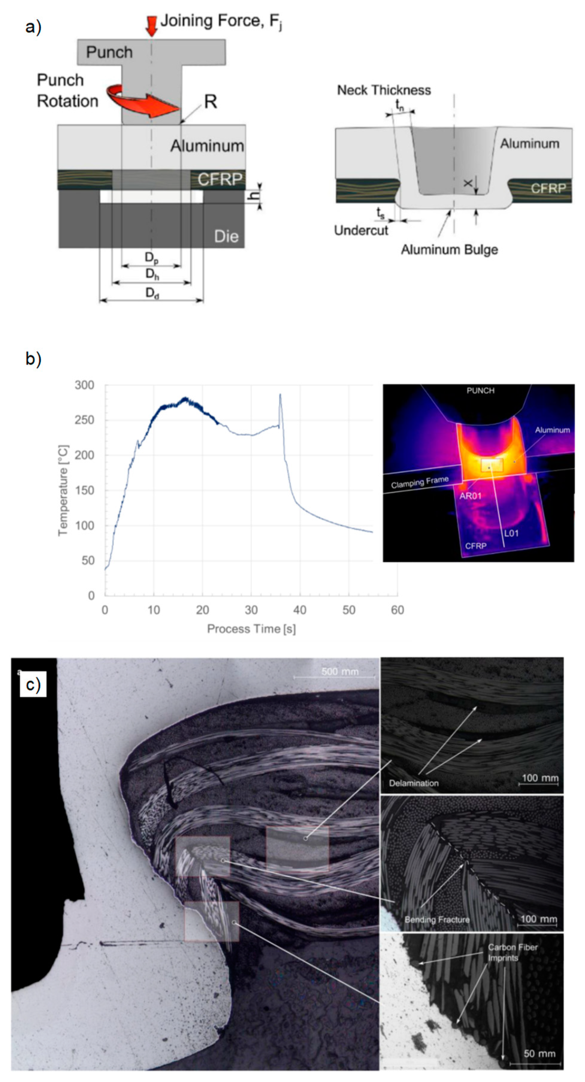
When joining metals and composites, the deformability of the metal material and the forming forces required for the joining are also important factors that limit the joining process. Traditional low-temperature thermal softening enhances the deformability of composites but has a limited impact on metals with low fracture limits. The friction-assisted clinching process introduced by Lambiase and Paoletti offers a solution by leveraging friction between the punch and the aluminum alloy. This approach achieves the required softening temperature, enhancing the deformability of the aluminum alloy and concurrently reducing the forming forces needed for joining. Consequently, the rigidity demands on the riveting equipment can be diminished [89].
During the joining process, the aluminum sheet is positioned on the punch side, while the pre-punched CFRP is placed on the die side. Joining is facilitated using a rotating cylindrical punch and a rigid die with a defined cavity (Figure 21a). Achieving a speed of 5400 rpm, the contact friction between the punch and the sheet allows the aluminum sheet to be heated to 280 °C within 10 s (Figure 21b). This softening effect results in a significant reduction of the maximum joining force to 300 N [89]. In comparison to conventional clinching under similar conditions, which typically demands a maximum joining force of 20–30 kN [90], friction-assisted clinching demonstrates promising potential in terms of minimizing process forces. The shear tensile strength of the joint is influenced by factors such as the punch radius (R), the diameter difference between the punch and the pilot hole (C), die depth (h), and the residual bottom thickness of the joint (X). In contrast to a conventional clinched joint, where the neck area typically exhibits material hardening up to 50% [91] resulting from the forming process, the hardness in the neck area of the friction-assisted clinched joint remains unchanged. This negligible hardening effect can be attributed to annealing occurring during the joining process. Significant material hardening is detectable mainly in the bottom area of the clinch joint. Moreover, the penetration of the aluminum induces deformation in the composite material as well. Delamination, fiber bending, and fiber fractures are typical failure modes (Figure 21c) [92].
4. Inspiration for Further Process Evolution
Various process modifications have been implemented for the clinching of CFRP with aluminum material, considering specific requirements. The advantages and disadvantages of these clinching variants are detailed in Table 1. It can be observed that heat-assisted joining processes are applicable only with thermoplastic composites, and the introduced heat may interfere when combined with adhesives. Clinching with a pre-hole, clinching with pre-forming, and friction-assisted clinching are well-suited for the joining of both thermoplastic and thermoset materials. Only clinching with pre-forming does not require a pre-hole operation, but it necessitates joining of the composite material before curing. In pre-hole joining processes, the pre-hole operation in CFRP and the hole location during joining pose critical challenges that hinder a straightforward process design. It is evident that a universally effective solution for pre-hole-free clinching of aluminum with cured CFRP, applicable to both thermoplastics and thermosets, is yet to be developed.
Upon scrutinizing current research, it becomes apparent that the incorporation of pre-holes in composites effectively eradicates material-related constraints in the joining process. Therefore, seamlessly integrating hole-making and clinching into a continuous operation could be a method to enhance the joint quality. For the joining of aluminum and ultra-high-strength steel in this way, shear clinching is carried out. In this method, the difficult-to-form steel initially undergoes shear cutting, followed by pushing through of the aluminum using a two-part punch [94]. This functional principle could be further applied to enhance the clinching of aluminum with CFRP. It is worth noting that shear cutting of the CFRP should be avoided due to the multilayer structure of the composite material, preventing the production of a clean fracture surface [60]. Achieving the required quality of the cut section can be achieved in other ways, such as laser cutting.
5. Conclusions and Outlook
This article delves into the constraints of common clinching processes when joining metal and CFRP. The joining processes are categorized into three groups, namely modification of structure, modification of material property, and multi-modification. The emphasis in process modification predominantly revolves around enhancing the formability of the composite material. The removal of composite material from the joining zone allows for independent modification of the joining process, irrespective of the matrix material properties. Nonetheless, a unified, single-stage solution seamlessly integrating hole-making and hole-finding in a continuous process remains elusive. In order to achieve that, various methods have been proposed to heat the composite materials beyond the glass transition temperature during joining process, although their efficacy is limited when dealing with thermosetting plastics.
Summarizing the current study, it was found that a versatile clinching method for aluminum alloy and CFRP that is adaptable to practical manufacturing is currently lacking. The future development of clinching technology can be guided by the following points:
- Clinching with material removal offers enhanced material versatility. In designing a material removal process, prioritizing integration into conventional clinching processes is crucial.
- The process should be meticulously designed to minimize damage to the composite material during material removal and joining. Understanding the interaction between removal and forming processes serves as the foundation for devising a seamless, continuous process.
- Mechanical properties of clinched joints need not excessively emphasize tensile strength. Instead, optimal load capacity hinges on better accommodating adhesives. The use of adhesives should steer clear of excessive preload and temperature effects during the joining process.
Author Contributions
D.H.: Conceptualization, methodology, investigation, formal analysis, writing—original draft, visualization, funding acquisition, and project administration. C.H.: Resources, methodology, writing—review and editing, and supervision. All authors have read and agreed to the published version of the manuscript.
Funding
The authors would like to acknowledge the financial support of the China Postdoctoral Science Foundation (Grant No. 2023M742221).
Conflicts of Interest
The authors declare that they have no known competing financial interests or personal relationships that could have appeared to influence the work reported in this paper.
References
- Jacob, A. Carbon fibre and cars-2013 in review. Reinf. Plast. 2014, 58, 18–19. [Google Scholar] [CrossRef]
- Ouyang, Y.; Chen, C. Research advances in the mechanical joining process for fiber reinforced plastic composites. Compos. Struct. 2022, 296, 115906. [Google Scholar] [CrossRef]
- Song, C.Y.; Lei, L.; Yan, M. Clinched joining mechanical performance in multiple states. Int. J. Adv. Manuf. Technol. 2023, 129, 3799–3812. [Google Scholar] [CrossRef]
- Zhang, W.; Xu, J. Advanced lightweight materials for automobiles: A review. Mater. Des. 2022, 221, 110994. [Google Scholar] [CrossRef]
- Astarita, A. Joining of Composite Materials: An Introduction. Encycl. Mater. Compos. 2021, 3, 302. [Google Scholar]
- Harries, K.A.; Peck, A.J.; Abraham, E.J. Enhancing stability of structural steel sections using FRP. Thin-Walled Struct. 2009, 47, 1092–1101. [Google Scholar] [CrossRef]
- Hesse, H.; Lukaszewicz, H.J.A.; Duddeck, F. A method to reduce design complexity of automotive composite structures with respect to crashworthiness. Compos. Struct. 2015, 129, 236–249. [Google Scholar] [CrossRef]
- Wei, J.; Sun, L.; Lv, W.; Wang, J.; Wang, Z.; Duan, Y.; Li, L. Integrated design and experimental verification of assembly fiber reinforced thermoplastic plastics (AFRTP) automobile seat beams. Compos. Part B Eng. 2021, 220, 108968. [Google Scholar] [CrossRef]
- Yao, L.M.; Tan, S.Q.; Xu, Z.W. Towards carbon neutrality: What has been done and what needs to be done for carbon emission reduction. Environ. Sci. Pollut. Res. 2022, 30, 20570–20589. [Google Scholar] [CrossRef]
- Choi, J.Y.; Jeon, J.H.; Lyu, J.H.; Park, J.; Kim, G.Y.; Chey, S.Y.; Quan, Y.-J.; Bhandari, B.; Prusty, B.G.; Ahn, S.-H. Current Applications and Development of Composite Manufacturing Processes for Future Mobility. Int. J. Precis. Eng. Manuf. Technol. 2023, 10, 269–291. [Google Scholar] [CrossRef]
- Pejman, R.; Gorman, J.; Najaf, A.R. Multi-physics design of a new battery packaging for electric vehicles utilizing multifunctional composites. Compos. Part B Eng. 2022, 237, 109810. [Google Scholar] [CrossRef]
- Qbau, N.; Nam, N.D.; Hien, N.T.; Ca, N.X. Development of light weight high strength aluminum alloy for selective laser melting. J. Mater. Res. Technol. 2020, 9, 14075–14081. [Google Scholar] [CrossRef]
- Meng, F.; Li, W.; Fan, H.; Zhou, Y. A nonlinear theory for CFRP strengthened aluminum beam. Compos. Struct. 2015, 131, 574–577. [Google Scholar] [CrossRef]
- Liu, Q.; Shen, H.; Wu, Y.; Xia, Z.; Fang, J.; Li, Q. Crash responses under multiple impacts and residual properties of CFRP and aluminum tubes. Compos. Struct. 2018, 194, 87–103. [Google Scholar] [CrossRef]
- Afseth, A. Aluminum Battery Enclosure Design, Constellium. Available online: https://www.cargroup.org/wp-content/uploads/2021/02/Aluminum-Battery-Enclosures-Constellium-February-2021-FINAL.pdf (accessed on 1 May 2024).
- Constellium Develops New Alloys for EV Battery Enclosures, SAE International. 19 February 2021. Available online: https://www.sae.org/news/2021/02/constellium-aluminum-ev-battery-enclosures (accessed on 1 May 2024).
- Gude, M.; Stegelmann, M.; Müller, M.; Demnitz, K. Studie zum ressourceneffizienten Leichtbau. Light. Des. 2018, 11, 30–35. [Google Scholar] [CrossRef]
- DIN 8593-5; Fertigungsverfahren Fuegen-Teil 5: Fuegen Durch Umformen; Einordnung, Unterteilung, Begriffe. Beuth Verlag GmbH: Berlin, Germany, 2003.
- Hahn, O.; Klemens, U. Fügen Durch Umformen: Nieten und Durchsetzfügen; Innovative Verbindungsverfahren für Die Praxis; Verlag und Vertriebsges: Heidelberg, Germany, 1996. [Google Scholar]
- Meschut, G.; Janzen, V.; Olfermann, T. Innovative and Highly Productive Joining Technologies for Multi-Material Lightweight Car Body Structures. J. Mater. Eng. Perform. 2014, 23, 1515–1523. [Google Scholar] [CrossRef]
- Meng, Y.C.; Cao, B.Q.; Qiu, Y.; Chen, H.; Xie, Y.; Wan, L.; Huang, Y. Equal-load-bearing joining of alclad AA2024-T4 alloy stringers and skins in aviation via friction stir lap welding. J. Manuf. Process. 2021, 68, 1295–1302. [Google Scholar] [CrossRef]
- Meschut, G.; Merklein, M.; Brosius, A.; Drummer, D.; Fratini, L.; Füssel, U.; Gude, M.; Homberg, W.; Martins, P.; Bobbert, M.; et al. Review on mechanical joining by plastic deformation. J. Adv. Join. Process. 2022, 5, 100113. [Google Scholar] [CrossRef]
- DIN 2304-1: 2016; Adhesive Bonding Technology-Quality Requirements for Bonding Processes-Part: 1: Bonding Process Chain. Beuth Verlag: Berlin, Germany, 2016.
- Ouyang, X.; Chen, C. Research on the joining of aluminum alloy and high-strength steel by dieless clinched-adhesive processes. J. Mater. Res. Technol. 2023, 24, 5526–5540. [Google Scholar] [CrossRef]
- Gleich, H.; Hartwig, A.; Lohse, H. Why pretreatment is so important. In Adhesion: Adhesives and Sealants; Springer Vieweg: Wiesbaden, Germany, 2016. [Google Scholar]
- Li, Y.B.; Ma, Y.W.; Lou, M.; Zhang, G.; Zhang, Q.; Qi, L.; Deng, L. Advances in Spot Joining Technologies of Light-weight Thin-walled Structures. J. Mech. Eng. 2020, 56, 125–146. [Google Scholar]
- Wippo, V.; Winter, Y.; Jaeschke, P.; Suttmann, O.; Kaierle, S.; Overmeyer, L. Temperature distribution during laser based heat conduction welding of CFRP. Procedia CIRP 2018, 74, 553–556. [Google Scholar] [CrossRef]
- Biswal, A.K.; Nandi, A.; Wang, H.; Vashisth, A. Ultrasonic welding of fiber reinforced vitrimer composites. Compos. Sci. Technol. 2023, 242, 110202. [Google Scholar] [CrossRef]
- Hicks, J. Welded Joint Design, 3rd ed.; Woodhead Publishing: Sawston, UK, 1990. [Google Scholar]
- Kah, P.; Suoranta, R.; Martikainen, J. Joining of Sheet Metals Using Different Welding Processes. In Proceedings of the 16th International Conference, Mechanika, Lithuania, 7–8 April 2011. [Google Scholar]
- Wang, R.; Jiang, D.X.; Zhang, Q.X.; Wang, H.; Zhang, J.; Sun, Y. Effect of Arc Welding Repair on Sealing Performance of resistance Weld-Bonded Structure. Mach. Des. Res. 2021, 37, 96–100. [Google Scholar]
- Huang, S.; Xu, L.; Lou, M.; Chen, H.; Zhang, K.; Li, Y. Keyhole-induced pore formation mechanism in la-ser-MIG hybrid welding of aluminum alloy based on experiment and multiphase numerical model. J. Mater. Process. Technol. 2023, 314, 117903. [Google Scholar] [CrossRef]
- Ambrosio, D.; Sharma, A.; Mukuda, M.; Morisada, Y.; Fujii, H. Feasibility of friction stir welding using a hemispherical tool tilted towards the retreating side. J. Adv. Join. Process. 2024, 9, 100180. [Google Scholar] [CrossRef]
- Günter, H.; Meschut, G. Joining of ultra-high-strength steels using resistance element welding on conventional resistance spot welding guns. Weld. World 2021, 65, 1899–1914. [Google Scholar] [CrossRef]
- Bu, H.; Gao, Q.; Li, Y.; Wang, F.; Zhan, X. Comparative Study on Microstructure and Aluminum Distribution Between Laser Beam Welding and Electron Beam Welding of Ti–6Al–4V Alloy Plates. Met. Mater. Int. 2021, 27, 3449–3461. [Google Scholar] [CrossRef]
- Singh, R. Applied Welding Engineering, 3rd ed.; Butterworth-Heinemann: Oxford, UK, 2020. [Google Scholar]
- Qin, Y.; Jiao, Z.; Feng, Z.; Shi, N.; Han, J.; Wei, X. Influence of Welding Sequence on Welding Deformation of T-Joint. In Transactions on Intelligent Welding Manufacturing; Springer: Singapore, 2020. [Google Scholar]
- Go, B.S.; Oh, K.H.; Kwon, S.I.; Bang, H.-S. Reduction Characteristics of Welding Deformation According to Cooling Distance in Heat Sink Welding. Int. J. Precis. Eng. Manuf. 2022, 23, 1229–1236. [Google Scholar] [CrossRef]
- Nourani, S.A.; Pons, D.J.; Tamadon, A.; Symons, D. Microstructural deformation in the clinching process. J. Adv. Join. Process. 2021, 3, 100041. [Google Scholar] [CrossRef]
- Meschut, G.; Janzen, V.; Matzke, M.; Olfermann, T. Comparison of Innovative Thermal Joining Technologies for Joining Ultra-High-Strength Steels in Multi-Material Structures, DVS-Berichte, Band 296; DVS Media GmbH: Berlin, Germany, 2013. [Google Scholar]
- Ma, Y.; Akita, R.; Abe, Y.; Geng, P.; Luo, P.; Tsutsumi, S.; Ma, N. Mechanical Performance Evaluation of Multi-Point Clinch–Adhesive Joints of Aluminum Alloy A5052-H34 and High-Strength Steel JSC780. Automot. Innov. 2023, 6, 340–351. [Google Scholar] [CrossRef]
- Lee, H.S. 10-Diffusion bonding of metal alloys in aerospace and other applications. In Welding and Joining of Aerospace Materials; Woodhead Publishing: Sawston, UK, 2021; pp. 305–327. [Google Scholar]
- Ying, L.; Dong, Q.; Gao, T.; Dai, M.; Hu, P. Self-piercing riveting of dissimilar carbon fiber-reinforced composites and aluminum alloy sheets: State-of-the-art achievements. Int. J. Adv. Manuf. Technol. 2023, 130, 1–22. [Google Scholar] [CrossRef]
- Pramanik, A.; Basak, A.K.; Dong, Y.; Sarker, P.K.; Uddin, M.S.; Littlefair, G.; Dixit, A.R.; Chattopadhyaya, S. Joining of carbon fibre reinforced polymer (CFRP) composites and aluminium alloys—A review. Compos. Part A Appl. Sci. Manuf. 2017, 101, 1–29. [Google Scholar] [CrossRef]
- Troschitz, J.; Gröger, B.; Würfel, V.; Kupfer, R.; Gude, M. Joining Processes for Fibre-Reinforced Thermoplastics: Phenomena and Characterisation. Materials 2022, 15, 5454. [Google Scholar] [CrossRef] [PubMed]
- Szlosarek, R.; Karall, T.; Enzinger, N.; Hahne, C.; Meyer, N. Mechanical testing of flow drill screw joints between fibre-reinforced plastics and metals. Mater. Test. 2013, 55, 737–742. [Google Scholar] [CrossRef]
- Podlesak, F.; Halsig, A.; Hofer, K.; Kaboli, R.; Mayr, P. Spin blind-riveting: Secure joining of plastic with metal. Weld. World 2015, 59, 927–932. [Google Scholar] [CrossRef]
- Min, J.; Li, Y.; Li, J.; Carlson, B.E.; Lin, J. Friction stir blind riveting of carbon fiber-reinforced poly-mer composite and aluminum alloy sheets. Int. J. Adv. Manuf. Technol. 2015, 76, 1403–1410. [Google Scholar] [CrossRef]
- DVS/EFB 3420; Clinching-Basics. Verlag für Schweissen und Verwandte Verfahren: Düsseldorf, Germany, 2021.
- Groche, P.; Wohletz, S.; Brenneis, M.; Pabst, C.; Resch, F. Joining by forming—A review on joint mechanisms, applications and future trends. J. Mater. Process. Technol. 2014, 214, 1972–1994. [Google Scholar] [CrossRef]
- Qin, D.; Chen, C.; Li, H.; Ren, X. Investigation of the novel two-step flat clinching process to achieve double-sided flat surfaces on engineering structures. J. Braz. Soc. Mech. Sci. Eng. 2022, 44, 525. [Google Scholar] [CrossRef]
- Peng, H.; Chen, C.; Zhang, H.; Ran, X. Recent development of improved clinching process. Int. J. Adv. Manuf. Technol. 2020, 110, 3169–3199. [Google Scholar] [CrossRef]
- Kupfer, R.; Köhler, D.; Römisch, D.; Wituschek, S.; Ewenz, L.; Kalich, J.; Weiß, D.; Sadeghian, B.; Busch, M.; Krüger, J.; et al. Clinching of Aluminum Materials–Methods for the Continuous Characterization of Process, Microstructure and Properties. J. Adv. Join. Process. 2022, 5, 100108. [Google Scholar] [CrossRef]
- Schürmann, H. Konstruieren mit Faser-Kunststoff-Verbunden; Springer: Heidelberg, Germany, 2007; 13. [Google Scholar]
- Behrens, B.A.; Rolfes, R.; Vucetic, M.; Reinoso, J.; Vogler, M.; Grbic, N. Material Modelling of Short Fiber Rein-forced Thermoplastic for the FEA of a Clinching Test. Procedia CIRP 2014, 18, 250–255. [Google Scholar] [CrossRef]
- Ning, H.B.; Lu, N.; Hassen, A.A.; Chawla, K.; Selim, M.; Pillay, S. A review of Long fibre thermoplastic (LFT) composites. Int. Mater. Rev. 2020, 65, 164–188. [Google Scholar] [CrossRef]
- Petrů, M.; Novák, O. FEM Analysis of Mechanical and Structural Properties of Long Fiber-Reinforced Composites, Finite Element Method–Simulation, Numerical Analysis and Solution Techniques; IntechOpen: London, UK, 2018. [Google Scholar]
- Lambiase, F.; Ko, D.C. Feasibility of mechanical clinching for joining aluminum AA6082-T6 and Carbon Fiber Reinforced Polymer sheets. Mater. Des. 2016, 107, 341–352. [Google Scholar] [CrossRef]
- Lambiase, F.; Durante, M.; DiIlio, A. Fast joining of aluminum sheets with Glass Fiber Reinforced Polymer (GFRP) by mechanical clinching. J. Mater. Process. Technol. 2016, 236, 241–251. [Google Scholar] [CrossRef]
- Han, D.; Yang, K.; Meschut, G. Mechanical joining of glass fibre reinforced polymer (GFRP) through an innovative solid self-piercing rivet. J. Mater. Process. Technol. 2021, 296, 117182. [Google Scholar] [CrossRef]
- Lee, C.J.; Lee, S.H.; Lee, J.M.; Kim, B.H.; Kim, B.M.; Ko, D.C. Design of Hole-Clinching Process for Joining CFRP and Aluminum Alloy Sheet. Int. J. Precis. Eng. Manuf. 2014, 15, 1151–1157. [Google Scholar] [CrossRef]
- Hörhold, R.; Müller, M.; Merklein, M.; Meschut, G. Mechanical properties of an innovative shear-clinching technology for ultra-high-strength steel and aluminium in light-weight car body structures. Weld. World 2016, 60, 613–620. [Google Scholar] [CrossRef]
- Lee, S.H.; Lee, C.J.; Lee, K.H.; Lee, J.M.; Kim, B.M.; Ko, D.C. Influence of tool shape on hole clinching for car-bon fiber-reinforced plastic and SPRC440. Adv. Mech. Eng. 2015, 6, 810864. [Google Scholar] [CrossRef]
- Liu, Y.; Zhuang, W.M.; Wu, S.J. Damage to carbon fibre reinforced polymers (CFRP) in hole-clinched joints with aluminium alloy and CFRP. Compos. Struct. 2020, 234, 111710. [Google Scholar] [CrossRef]
- Han, W.Q.; Hu, K.J.; Shi, Q.H.; Zhu, F. Damage evolution analysis of open-hole tensile laminated composites using a progress damage model verified by AE and DIC. Compos. Struct. 2020, 247, 112452. [Google Scholar] [CrossRef]
- Busse, S.; Merklein, M.; Roll, K.; Ruther, M.; Zürn, M. Development of a mechanical joining process for automotive body-in-white production. Int. J. Mater. Form. 2010, 3, 1059–1062. [Google Scholar] [CrossRef]
- Chen, C.; Zhao, S.D.; Han, X.L.; Cui, M.; Fan, S. Investigation of mechanical behavior of the re-shaped joints realized with different reshaping forces. Thin-Walled Struct. 2016, 107, 266–273. [Google Scholar] [CrossRef]
- Lee, C.J.; Kim, B.M.; Kang, B.S.; Song, W.-J.; Ko, D.-C. Improvement of joinability in a hole clinching process with aluminum alloy and carbon fiber reinforced plastic using a spring die. Compos. Struct. 2017, 173, 58–69. [Google Scholar] [CrossRef]
- Lee, C.J.; Lee, J.M.; Ryu, H.Y.; Lee, K.H.; Kim, B.M.; Ko, D.C. Design of hole-clinching process for joining of dis-similar materials–Al6061-T4 alloy with DP780 steel, hot pressed 22MnB5 steel, and carbon fiber reinforced plastic. J. Mater. Process. Technol. 2014, 214, 2169–2178. [Google Scholar] [CrossRef]
- Latorre, N.; Casellas, D.; Costa, J. A punching process to join metal sheets and fibre reinforced polymer composites by mechanical interlocking. Compos. Part A Appl. Sci. Manuf. 2023, 175, 107744. [Google Scholar] [CrossRef]
- Lin, P.C.; Lin, J.W.; Li, G.X. Clinching process for aluminum alloy and carbon fiber-reinforced thermoplastic sheets. Int. J. Adv. Manuf. Technol. 2018, 97, 529–541. [Google Scholar] [CrossRef]
- Vorderbrüggen, J.; Gröger, B.; Kupfer, R.; Hoog, A.; Gude, M.; Meschut, G. Phenomena of forming and failure in joining hybrid structures-Experimental and numerical studies of clinching thermo-plastic composites and metal. AIP Conf. Proc. 2019, 2113, 050016. [Google Scholar]
- Schramm, B.; Friedlein, J.; Gröger, B.; Bielak, C.; Bobbert, M.; Gude, M.; Meschut, G.; Wallmersperger, T.; Mergheim, J. A Review on the Modeling of the Clinching Process Chain—Part II: Joining Process. J. Adv. Join. Process. 2022, 6, 100134. [Google Scholar] [CrossRef]
- Meschut, G.; Vorderbrüggen, J.; Gude, M.; Kupfer, R.; Gröger, B. Entwicklung eines Clinchverfahrens für Thermoplastische FKV in Mischbauweise; EFB-Forschungsbericht Nr. 524: Hannover, Germany, 2019; p. 29. [Google Scholar]
- Yarcu, S.; Behrens, B.A.; Huebner, S.; Schuchardt, T.; Dilger, K.; Meichsner, T.P. Clinching of inductively heated aluminum die casting. Prod. Eng. 2022, 16, 223–233. [Google Scholar] [CrossRef]
- Gemeinsame Forschung in der Mechanischen Fügetechnik 2023. EFB Europäische Forschungsgesellschaft für Blechverarbeitung e.V.–FOSTA Forschungsvereinigung Stahlanwendung e.V. Tagungsband T 54. 2023. Available online: https://www.fuegetechnik.org/fk-programm.html (accessed on 1 May 2024).
- Lin, P.C.; Lo, S.M. Friction stir clinching of alclad AA2024-T3 sheets. Int. J. Adv. Manuf. Technol. 2017, 92, 2425–2437. [Google Scholar] [CrossRef]
- Tatsuno, D.; Yineyama, T.; Kawamoto, K.; Okamoto, M. Hot press forming of thermoplastic CFRP sheets. Procedia Manuf. 2018, 15, 1730–1737. [Google Scholar] [CrossRef]
- Härtel, S.; Graf, M.; Gerstmann, T.; Awiszus, B. Heat Generation During Mechanical Joining Processes–by the Example of Flat-Clinching. Procedia Eng. 2017, 184, 251–265. [Google Scholar] [CrossRef]
- Seidlitz, H.; Czech, A.; Ulke-Winter, L.; Kroll, L. Thermomechanisches Ausform-fügen für thermoplastische FVK. Lightweight Des. 2011, 3, 16–23. [Google Scholar] [CrossRef]
- Seidlitz, H.; Ulke-Winter, L.; Kroll, L. New Joining Technology for Optimized Met-al/Composite Assemblies. J. Eng. 2014, 2014, 958501. [Google Scholar]
- Gude, M.; Hufenbach, W.; Vogel, C.; Freund, A.; Kupfer, R. Thermoclinching—A novel joining process for lightweight structures in multimaterial design. Compos. Theory Pract. 2014, 14, 128–133. [Google Scholar]
- Gude, M.; Hufenbach, W.; Kupfer, R.; Freund, A.; Vogel, C. Development of novel form-locked joints for textile reinforced thermoplastices and metallic components. J. Mater. Process. Technol. 2015, 216, 140–145. [Google Scholar] [CrossRef]
- Gude, M.; Freund, A.; Vogel, C. Numerical Simulation Based Process Development of the Novel Thermoclinching Technology for Textile Reinforced Thermoplastics. In Proceedings of the 20th international Conference on Composite Materials, Copenhagen, Danmark, 19–24 July 2015. [Google Scholar]
- Hufenbach, W.; Adam, F.; Kupfer, R. A novel textile-adapted notching technology for bolted joints in textile-reinforced thermoplastic composites. ECCM 2010, 461, 1–9. [Google Scholar]
- Troschitz, J.; Kupfer, R.; Gude, M. Process-integrated embedding of metal inserts in continuous fibre reinforced thermoplastics. Procedia CIRP 2019, 85, 84–89. [Google Scholar] [CrossRef]
- Troschitz, J.; Vorderbrüggen, J.; Gude, M.; Meschut, G. Clinching and resistance spot welding of thermoplastic composites with metals using inserts as joining interfaces. In Proceedings of the Twenty-Third International Conference on Composite Materials (ICCM23), Belfast, UK, 30 July–4 August 2023. [Google Scholar]
- Ma, Y.; Yu, Y.; Geng, P.; Ihara, R.; Maeda, K.; Suzuki, R.; Suga, T.; Ma, N. Fracture modeling of resistance spot welded ultra−high−strength steel considering the effect of liquid metal embrittlement crack. Mater. Des. 2021, 210, 110075. [Google Scholar] [CrossRef]
- Lambiase, F.; Paoletti, A.; DiIlio, A. Advances in Mechanical Clinching: Employment of a rotating tool. Procedia Eng. 2017, 183, 200–205. [Google Scholar] [CrossRef]
- Chen, C.; Zhao, S.; Cui, M.; Han, X.; Fan, S.; Ishida, T. An experimental study on the compressing process for joining Al6061 sheets. Thin-Walled Struct. 2016, 108, 56–63. [Google Scholar] [CrossRef]
- Müller, M.; Hörhold, R.; Merklein, M.; Meschut, G. Analysis of Material Behaviour in Experimental and Simulative Setup of Joining by Forming of Aluminium Alloy and High Strength Steel with Shear-Clinching Technology. Adv. Mater. Res. 2014, 966–967, 549–556. [Google Scholar] [CrossRef]
- Lambiase, F.; Paoletti, A. Friction-assisted clinching of Aluminum and CFRP sheets. J. Manuf. Process. 2018, 31, 12–22. [Google Scholar] [CrossRef]
- Latorre, N.; Casellas, D.; Costa, J.; Garcia-Llamas, E.; Pujante, J. Forming of mechanically interlocked aluminium and carbon fibre reinforced polymer parts with complex geometry. Mater. Res. Proc. 2024, 41, 1640–1649. [Google Scholar]
- Han, D.; Hörhold, R.; Müller, M.; Wiesenmayer, S.; Merklein, M.; Meschut, G. Shear-Clinching of Multi-Element Specimens of Aluminium Alloy and Ultra-High-Strength Steel. Key Eng. Mater. 2018, 767, 389–396. [Google Scholar] [CrossRef]
Figure 1.
Schematic representation of single-stage clinching. (a) Clinching without cutting using a rigid die; (b) clinching without cutting using an opening die; (c) clinching without cutting using a flat die; (d) clinching with cutting using an opening die.
Figure 1.
Schematic representation of single-stage clinching. (a) Clinching without cutting using a rigid die; (b) clinching without cutting using an opening die; (c) clinching without cutting using a flat die; (d) clinching with cutting using an opening die.
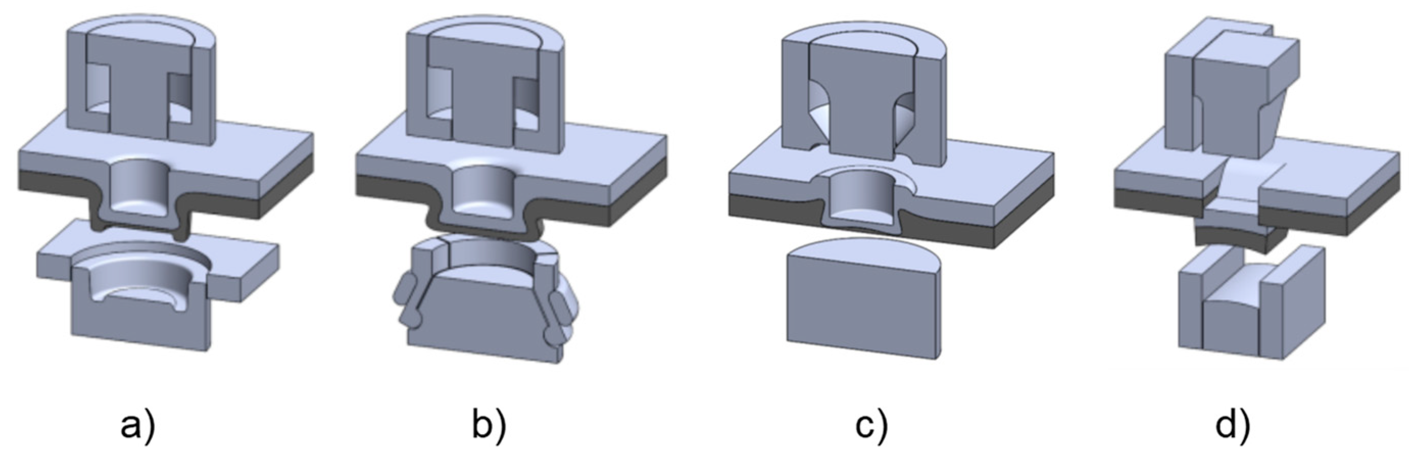
Figure 2.
Geometric characteristics of a round clinched joint.
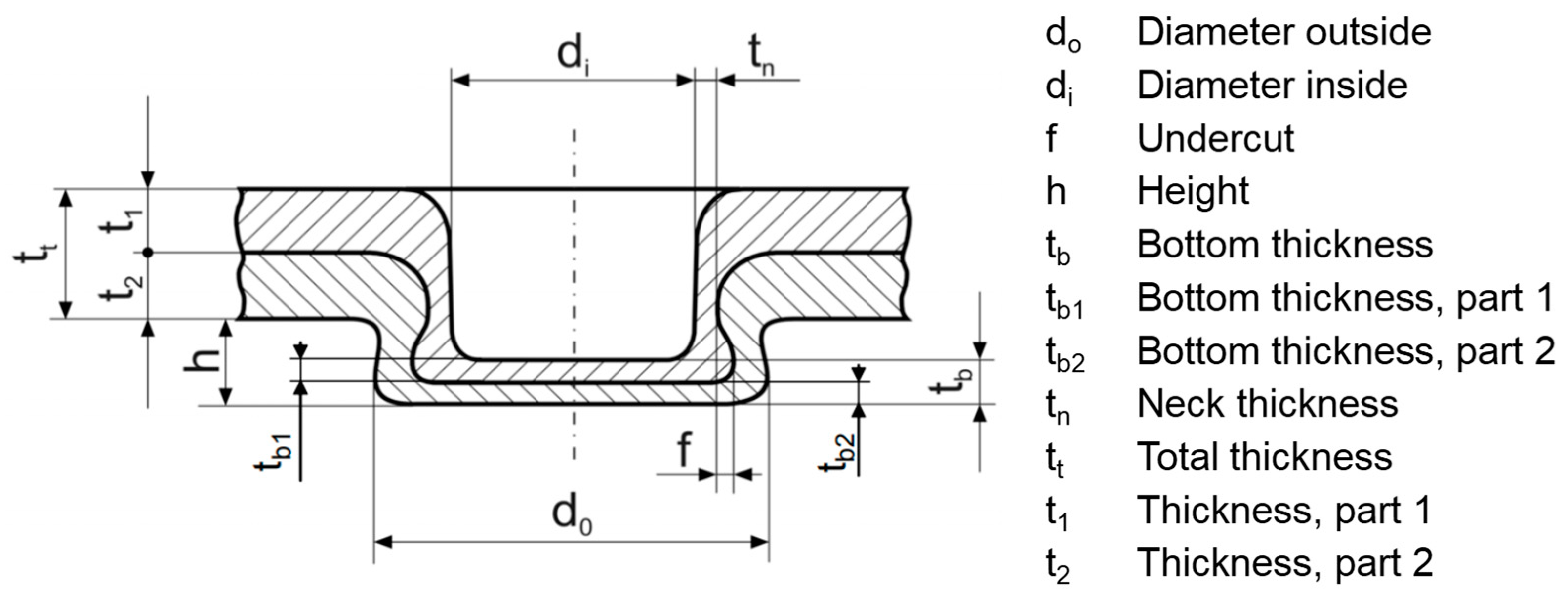
Figure 3.
Microstructural change in the joining partner after clinching (a–d). Reproduced with permission from [53]. 2022, Open Access by Elsevier.
Figure 3.
Microstructural change in the joining partner after clinching (a–d). Reproduced with permission from [53]. 2022, Open Access by Elsevier.
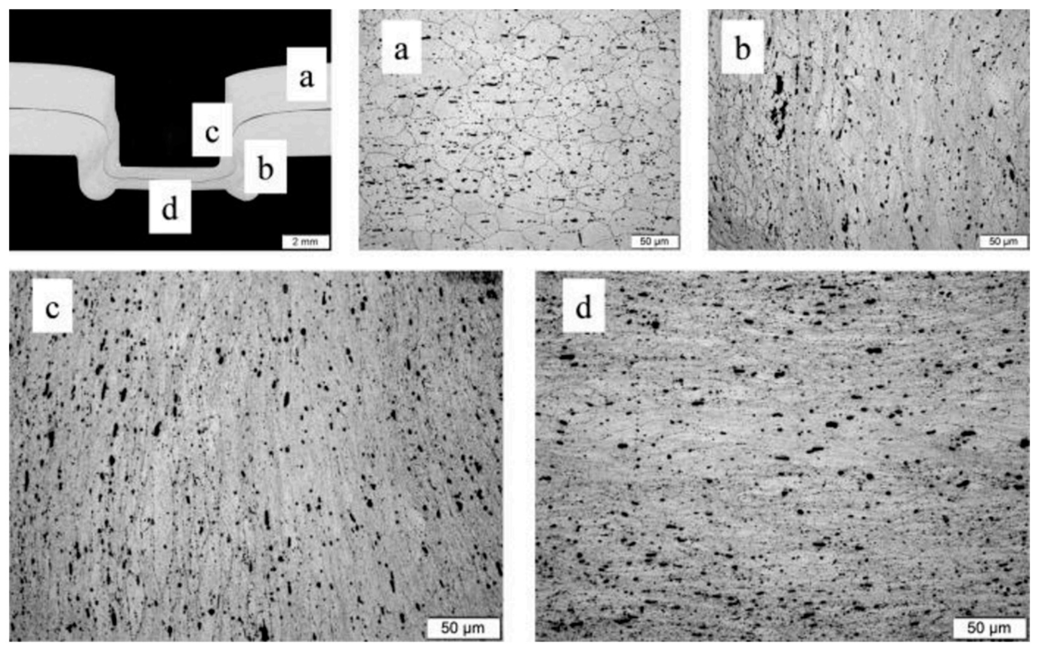
Figure 4.
Clinching CFRP and aluminum at room temperature. Reproduced with permission from [58]. 2016, Elsevier.
Figure 4.
Clinching CFRP and aluminum at room temperature. Reproduced with permission from [58]. 2016, Elsevier.
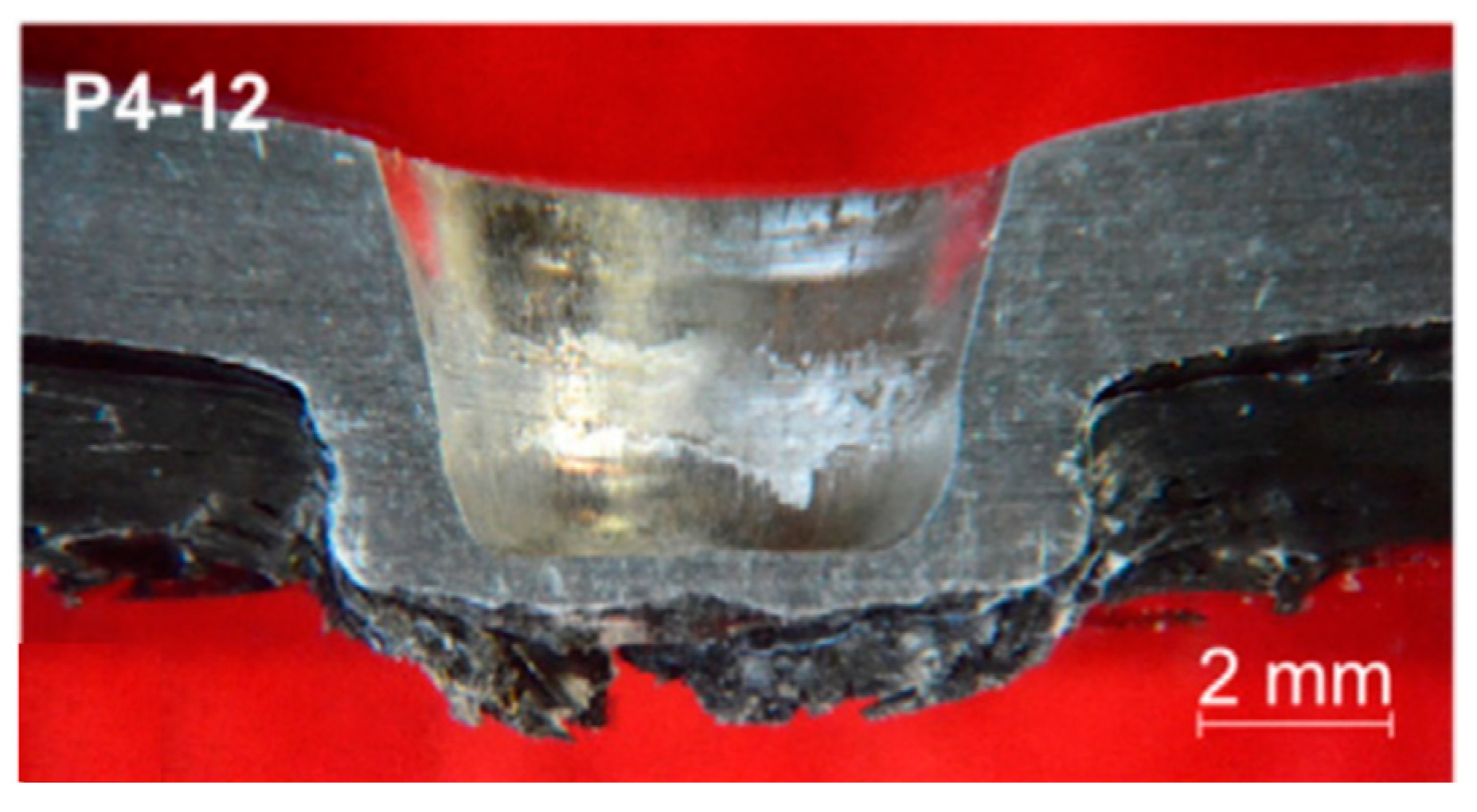
Figure 5.
Material flow and damage during clinching of aluminum and CFRP. (a) Offsetting; (b) upsetting; (c) flow pressing and spreading. Reproduced with permission from [59]. 2016, Elsevier.
Figure 5.
Material flow and damage during clinching of aluminum and CFRP. (a) Offsetting; (b) upsetting; (c) flow pressing and spreading. Reproduced with permission from [59]. 2016, Elsevier.
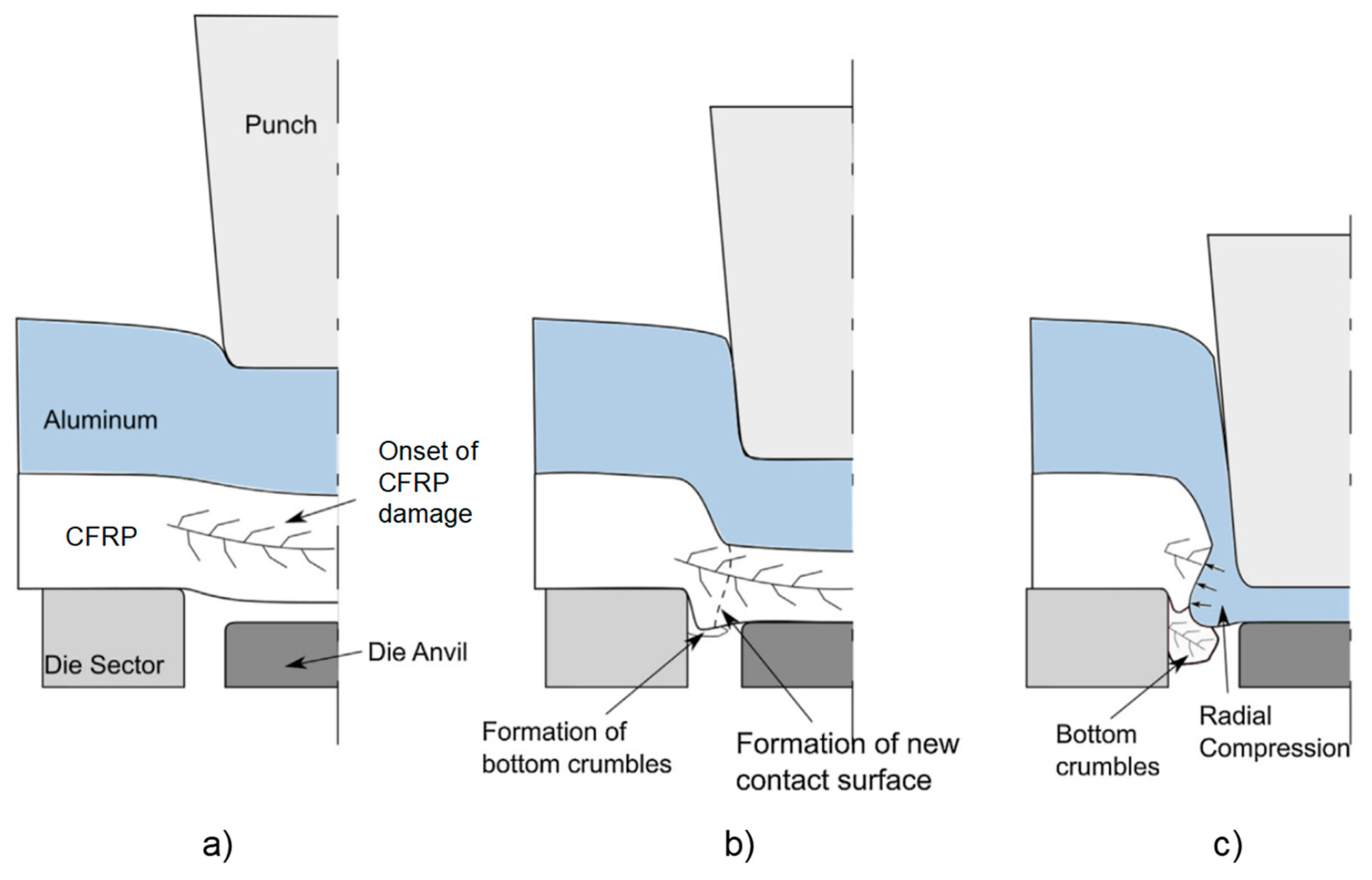
Figure 6.
Shear punching and curling of CFRP by clinching. Reproduced with permission from [58]. 2016, Elsevier.
Figure 6.
Shear punching and curling of CFRP by clinching. Reproduced with permission from [58]. 2016, Elsevier.

Figure 7.
The way to improve the joining quality of riveted composites and aluminum alloys.
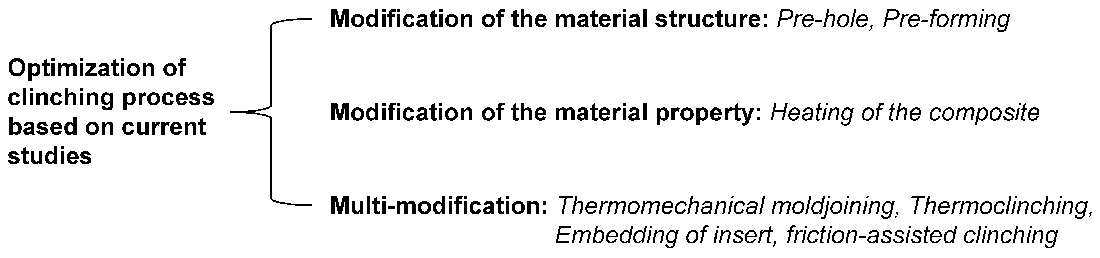
Figure 8.
Hole clinching for the joining of CFRP and aluminum alloy. (a) Schematic presentation of joining process; (b) load–stroke curve of joining process; (c) geometrical interlocking and dragging of clinched joint; (d) delamination of CFRP after joining. Reproduced with permission from [61]. 2014, Springer nature.

Figure 9.
Effect of tool geometry on clinch quality. Reproduced with permission from [63]. 2014, Open Access by Sage journals.
Figure 9.
Effect of tool geometry on clinch quality. Reproduced with permission from [63]. 2014, Open Access by Sage journals.
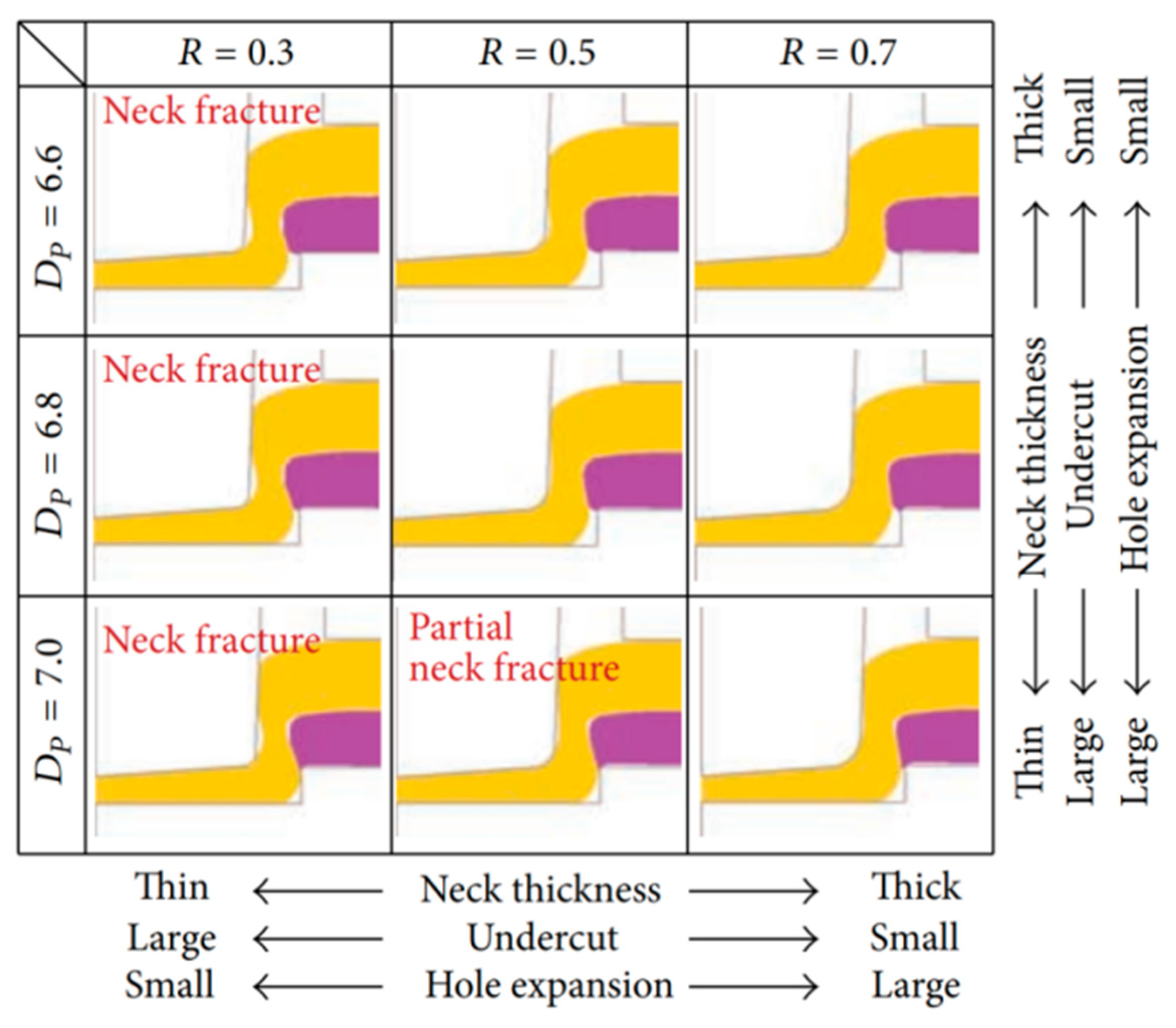
Figure 10.
Simulative prediction of damage in clinched CFRP. (a) 0° layer; (b) −45° layer; (c) 90° layer; (d) 45° layer. Reproduced with permission from [64]. 2020, Elsevier.
Figure 10.
Simulative prediction of damage in clinched CFRP. (a) 0° layer; (b) −45° layer; (c) 90° layer; (d) 45° layer. Reproduced with permission from [64]. 2020, Elsevier.

Figure 11.
Presentation of hydrostatic stress during hole clinching. (a) Conventional die; (b) spring die. Reproduced with permission from [68]. 2017, Elsevier.
Figure 11.
Presentation of hydrostatic stress during hole clinching. (a) Conventional die; (b) spring die. Reproduced with permission from [68]. 2017, Elsevier.

Figure 12.
Cross section of a spring die. Reproduced with permission from [68]. 2017, Elsevier.
Figure 12.
Cross section of a spring die. Reproduced with permission from [68]. 2017, Elsevier.
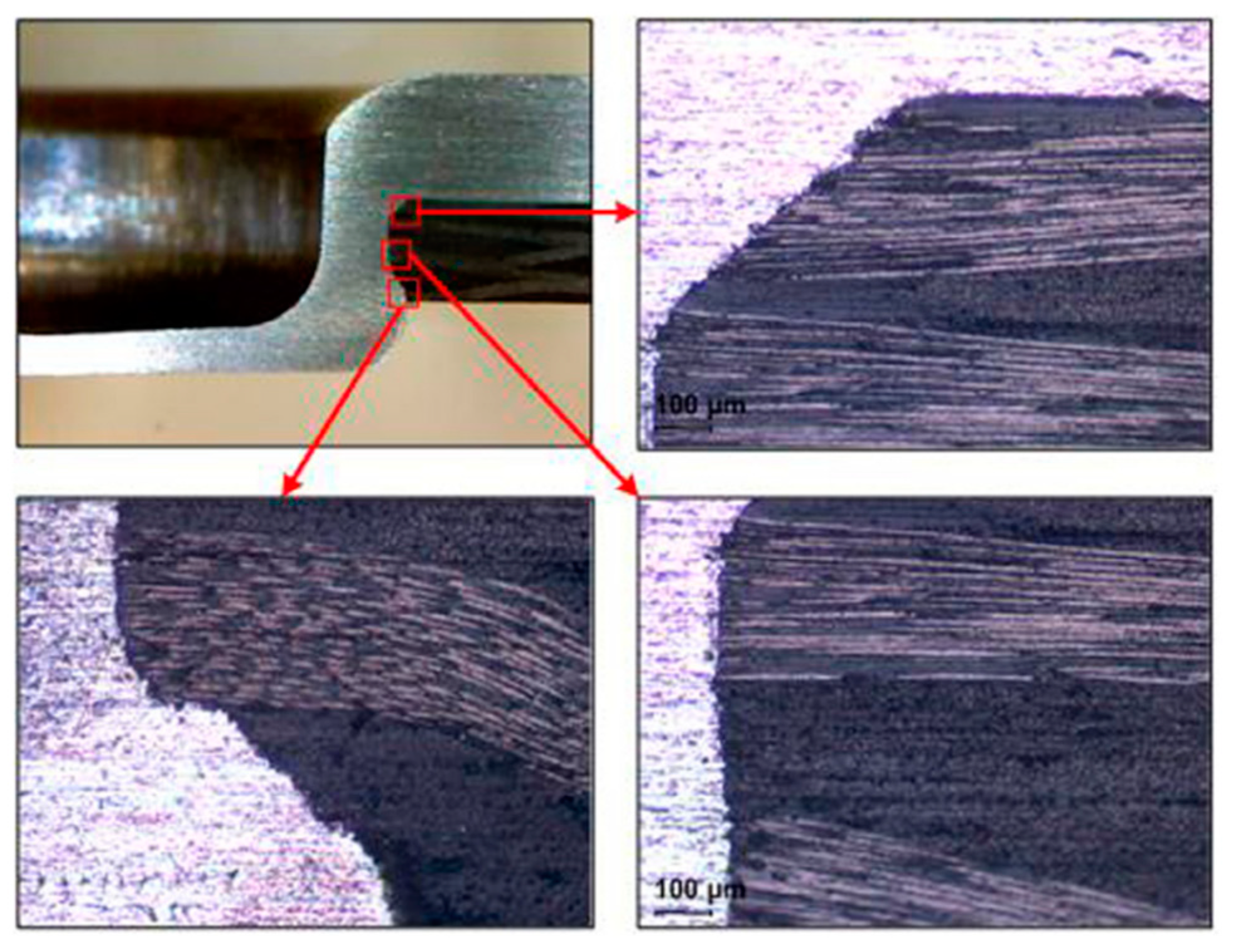
Figure 13.
Joining through pre-forming of the composite prior to curing. (a) Load–stroke curve of pre-forming process; (b) cross section of specimen; (c) comparison of shear load capacities in terms of different joining technologies. Reproduced with permission from [70]. 2023, Elsevier.
Figure 13.
Joining through pre-forming of the composite prior to curing. (a) Load–stroke curve of pre-forming process; (b) cross section of specimen; (c) comparison of shear load capacities in terms of different joining technologies. Reproduced with permission from [70]. 2023, Elsevier.
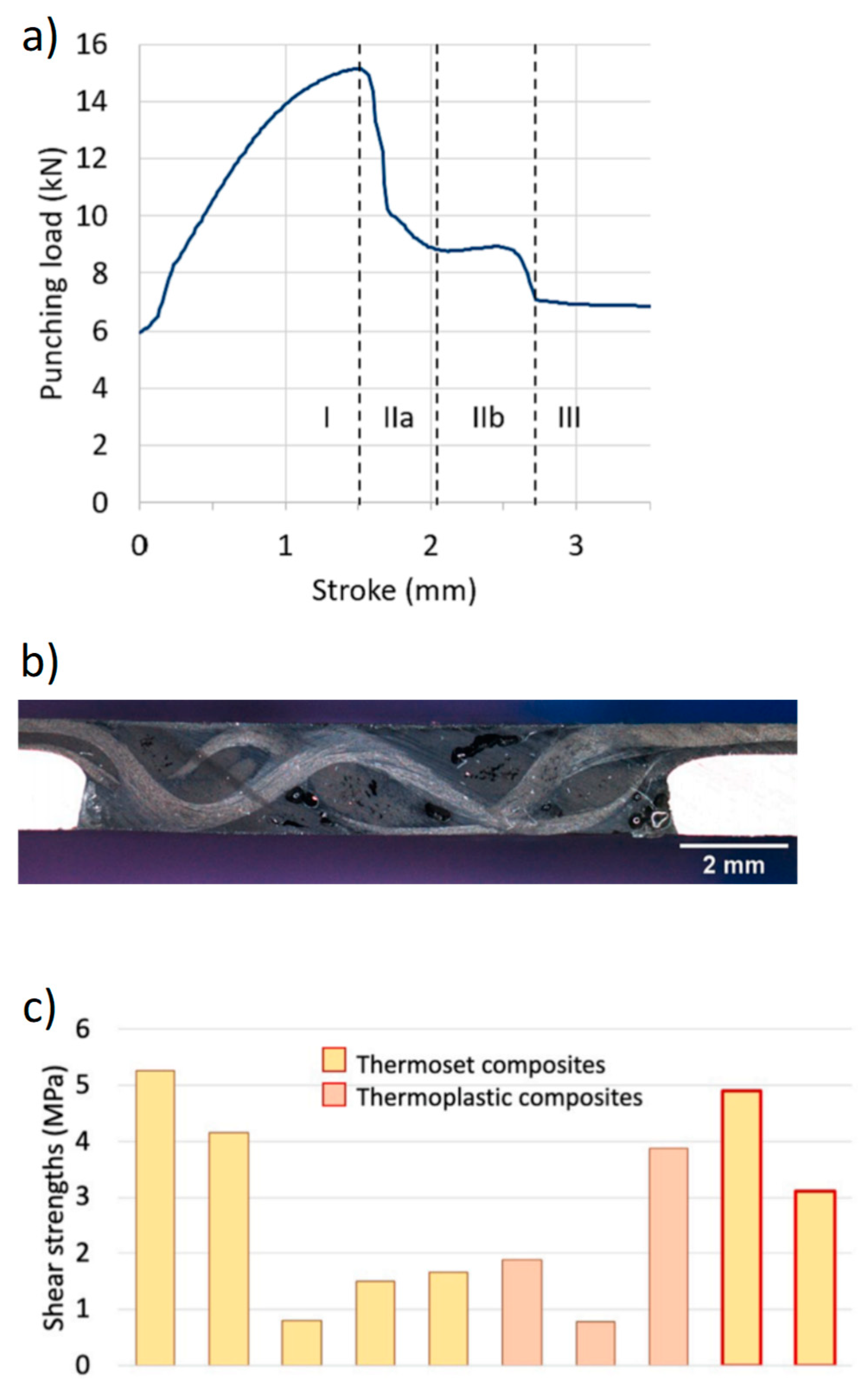
Figure 14.
Using hot clinching to join composite material with metal. (a) Cross section of clinched DC05 (t = 1.5 mm)–GFRP (t = 2.0 mm) joint at 30 °C; (b) cross section of clinched DC05 (t = 1.5 mm)–GFRP (t = 2.0 mm) joint at 170 °C. Reproduced with permission from [72]. 2019, AIP.
Figure 14.
Using hot clinching to join composite material with metal. (a) Cross section of clinched DC05 (t = 1.5 mm)–GFRP (t = 2.0 mm) joint at 30 °C; (b) cross section of clinched DC05 (t = 1.5 mm)–GFRP (t = 2.0 mm) joint at 170 °C. Reproduced with permission from [72]. 2019, AIP.
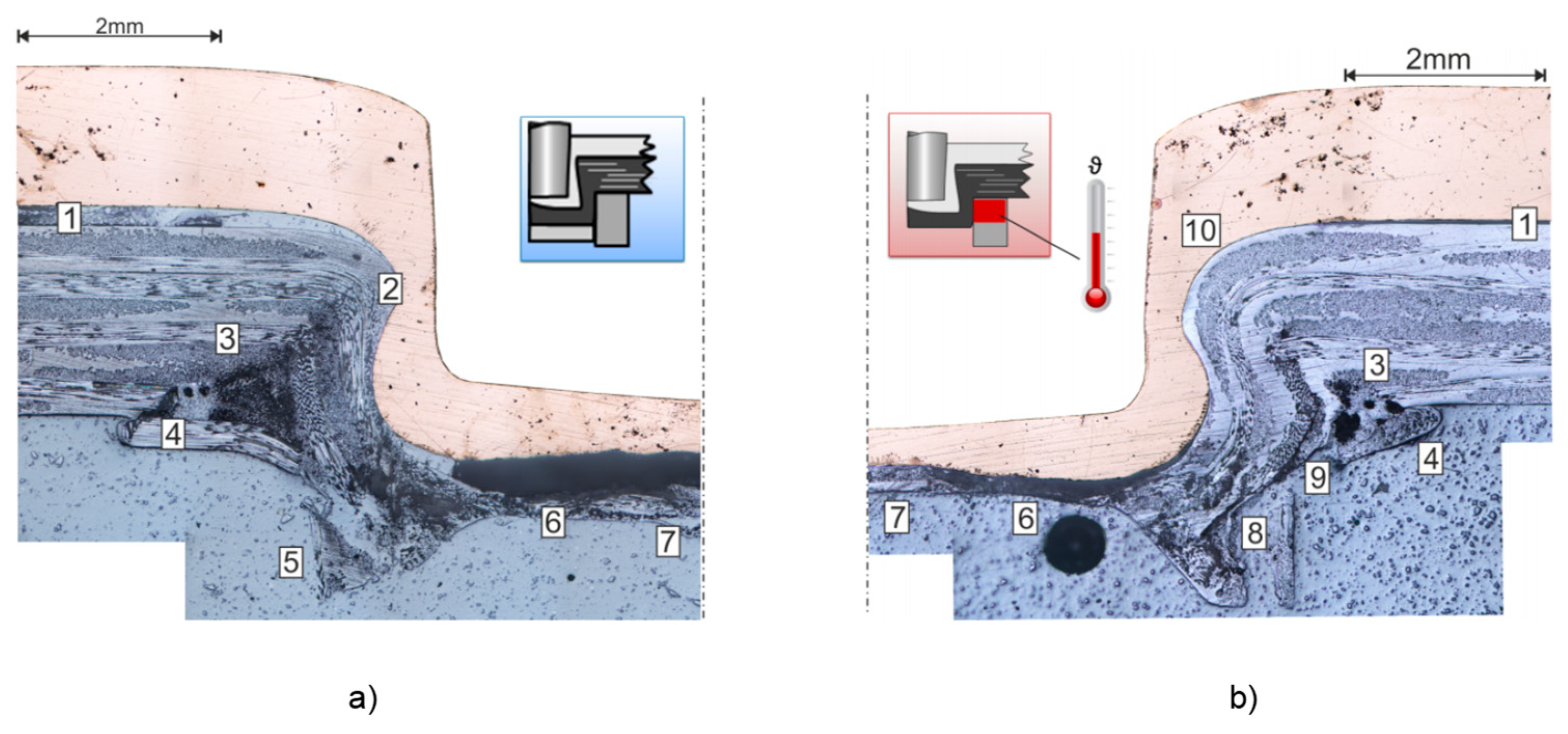
Figure 15.
Heat treatment methods used in clinching. (a) Inductive heating (reproduced with permission from [75]. 2022, Open Access by Springer nature); (b) laser heating [76].
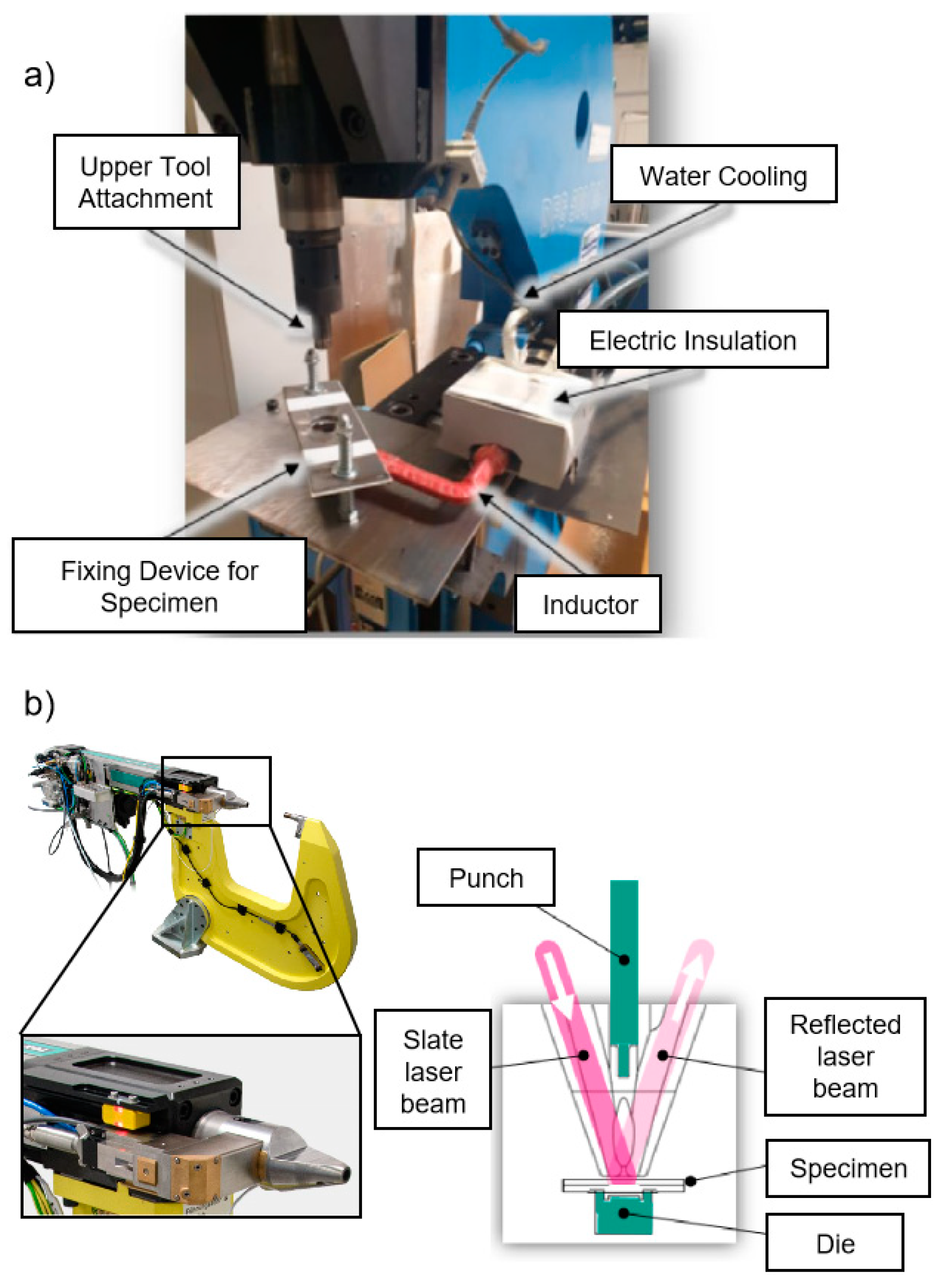
Figure 16.
Heat transfer on the interfaces during clinching. Reproduced with permission from [79]. 2017, Elsevier.
Figure 16.
Heat transfer on the interfaces during clinching. Reproduced with permission from [79]. 2017, Elsevier.
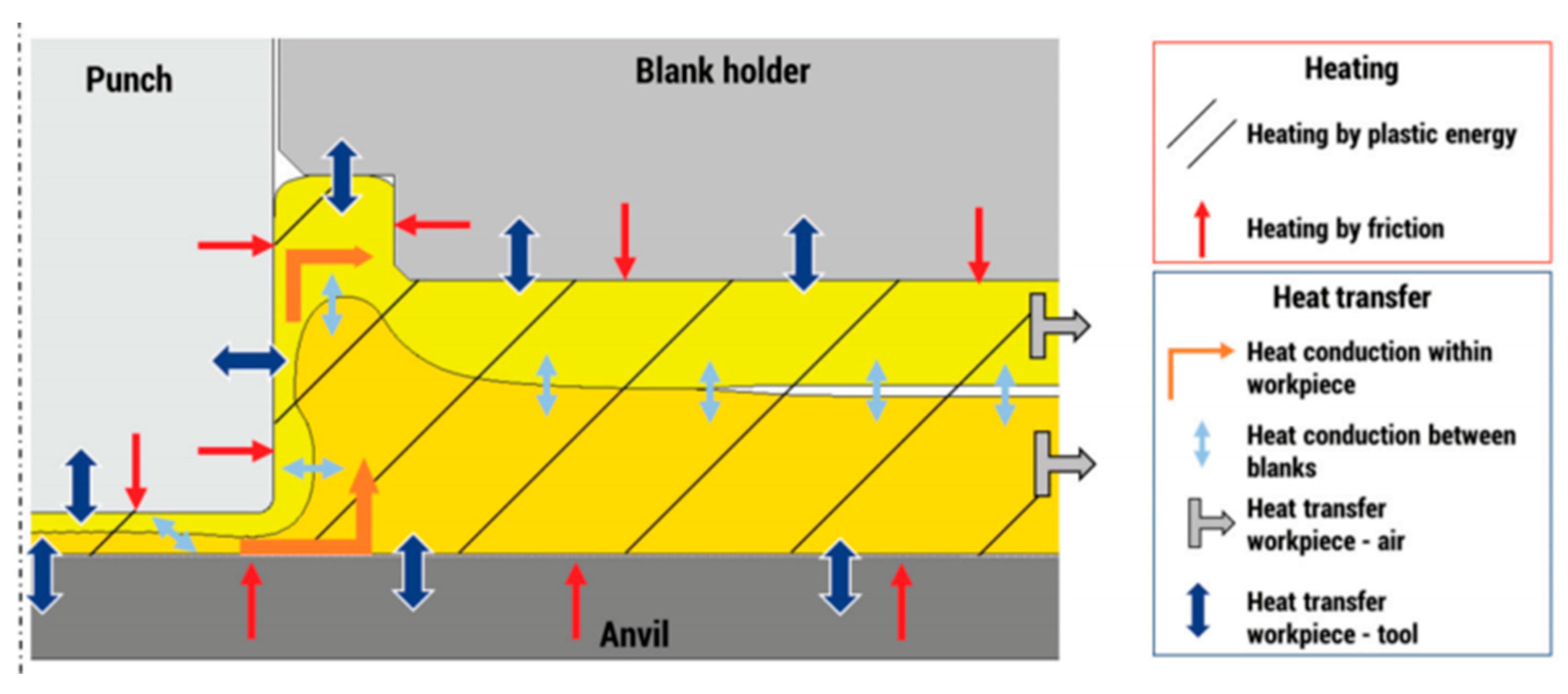
Figure 17.
Thermomechanical mold joining. (a) Process principle; (b) schematic presentation of realigned fibers in the joined specimen; (c) comparison of the maximum shear tensile force with load-adjusted formed and predrilled FRP bore holes; (d) inhomogeneous fiber content in the joining area. Reproduced with permission from [81]. 2014, Open Access by Hindawi.

Figure 18.
Thermoclinching. (a) Process principle (reproduced with permission from [84]. 2015, Open Access by ICCM); (b) computed tomography of composite deformation during the joining process (reproduced with permission from [83]. 2015, Elsevier); (c) pre-cutting of the composite sheet (reproduced with permission from [83]. 2015, Elsevier); (d) load–displacement curve of thermoclinching joint under shear tensile stress (reproduced with permission from [83]. 2015, Elsevier).
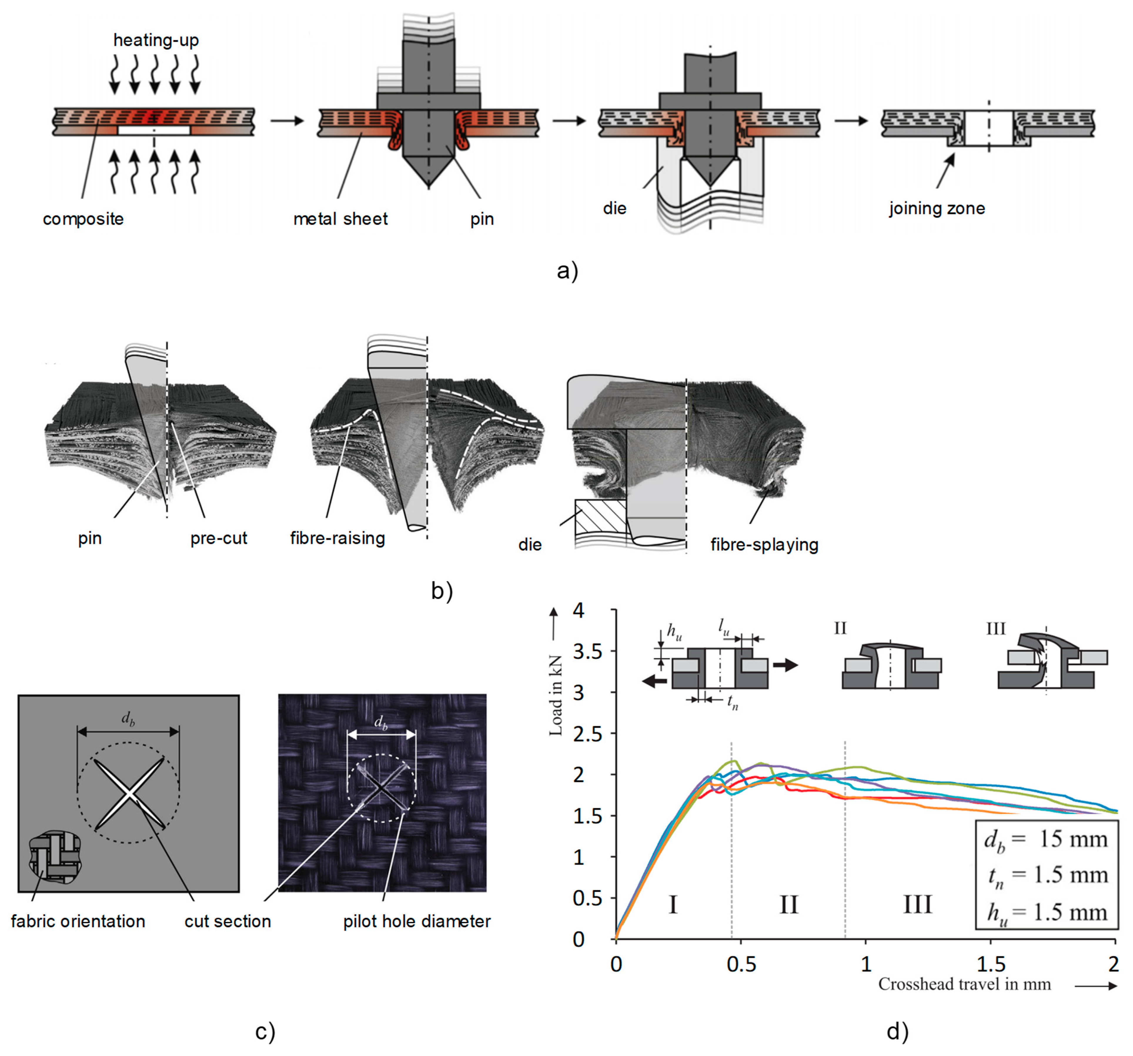
Figure 19.
Schematic presentation of embedding of inserts in composite sheet. Reproduced with permission from [87]. 2023, Open Access by ICCM. (a) heating, (b) preloading, (c) inserting, (d) forming, (e) finish.
Figure 19.
Schematic presentation of embedding of inserts in composite sheet. Reproduced with permission from [87]. 2023, Open Access by ICCM. (a) heating, (b) preloading, (c) inserting, (d) forming, (e) finish.
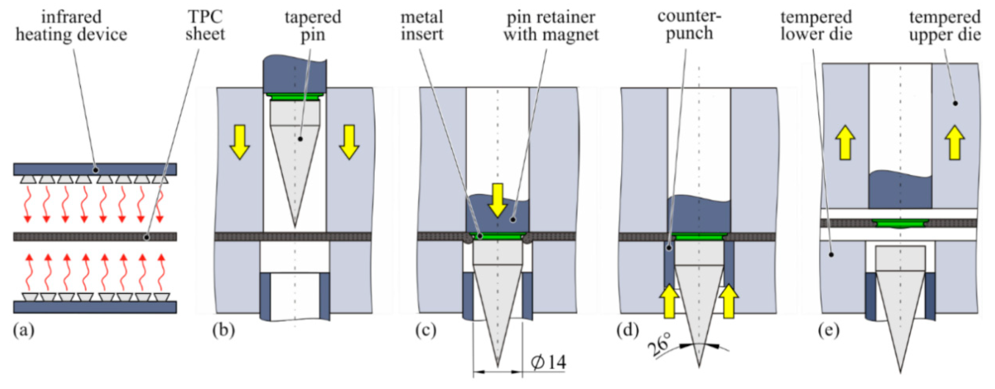
Figure 20.
Joining of metal with FRP after embedding of insert made of S235JR. (a,f) Cross section and tested specimen of clinched joint GF-PP with AA6016 T4; (b,g) cross section and tested specimen of clinched joint AA6016 T4 with GF-PP; (c,h) cross section and tested specimen of RSW joint GF-PP with HC340LA; (d) comparison of shear load capacity of different joining sequences; (e) shear load capacity of RSW joints. Reproduced with permission from [45]. 2022, Open Access by MDPI.
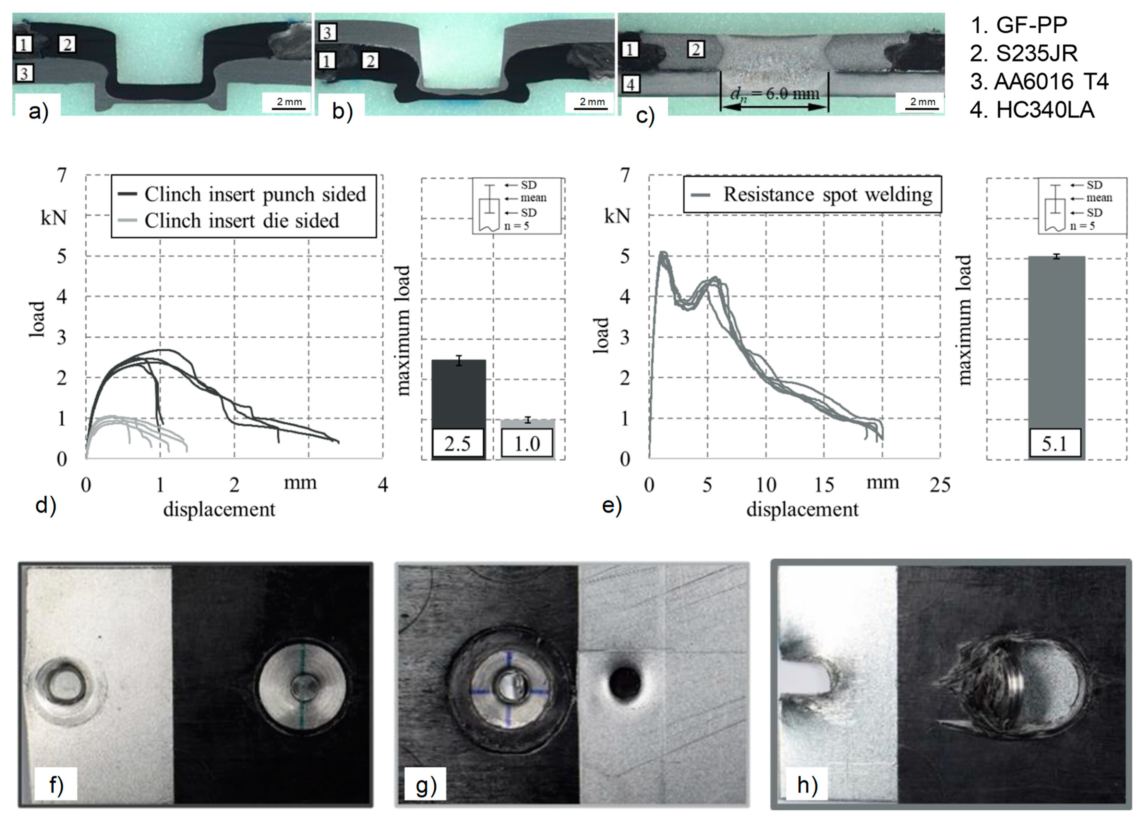
Figure 21.
Friction-assisted clinching of aluminum and CFRP [92]. (a) Joining setup and schematic presentation of joint cross section; (b) temperature development in the joining part during friction clinching; (c) composite fractures during friction clinching. Reproduced with permission from [92]. 2018, Elsevier.

Table 1.
Common clinching method for joining aluminum with composite materials.
| Clinching Method | Joined Materials | Advantages | Disadvantages |
|---|---|---|---|
| Clinching with pre-hole [61,63,64,68,69] | AA6061 (2.4 mm)/ CFRP (1.6 mm) [61] SPRC440 (1.2 mm) /CFRP (1.2 mm) [63] AA5754 (1.5 mm)/ CFRP (1.0 mm) [64] AA5083 (1.4 mm)/ CFRP (1.0 mm) [68] AA6061-T4 (2.0 mm)/ CFRP (1.6 mm) [69] |
|
|
| Clinching with pre-forming [70,93] | AA5754 H111 (1.5 mm)/ CFRP (0.65 mm) [70] AA5754 H111 (2.0 mm)/ CFRP (0.65 mm) [93] |
|
|
| Clinching with heating [71,72,74] | DC05 (1.5 mm)/ GF-PA6 (2.0 mm) [72,74] AA5052 H32 (1.6 mm)/ CFRTP (1.6 mm) [71] |
|
|
| Thermomechanical mold joining [80,94] | DC04 (1.5 mm)/ GF-PP (1.0 mm) [80] DC04 (1.5 mm)/ CFRP (2.0 mm) [81] DC04 (1.5 mm)/ GFRP (1.0 mm, 1.5 mm, 2.0 mm, 2.7 mm, 3.2 mm, 3.7 mm) [81] |
|
|
| Thermoclinching [82,83,84,85] | DC04 (1.0 mm)/ GF-PP (4.0 mm) [82,83,84,85] |
|
|
| Clinching after embedding of inserts [87,88] | 1.2210 (4.3 mm)/ GF-PP (4.3 mm) [45] AA6016-T4 (1.5 mm)/ GF-PP (2.15 mm) [87] HC340LA (1.5 mm)/ GF-PP (2.15 mm) [87] |
|
|
| Friction-assisted clinching [89,92] | AA6061 (2.0 mm)/ CFRP (1.4 mm) [89] AA6061 (2.0 mm)/ CFRP (2.0 mm) [92] |
|
|
Disclaimer/Publisher’s Note: The statements, opinions and data contained in all publications are solely those of the individual author(s) and contributor(s) and not of MDPI and/or the editor(s). MDPI and/or the editor(s) disclaim responsibility for any injury to people or property resulting from any ideas, methods, instructions or products referred to in the content. |
© 2024 by the authors. Licensee MDPI, Basel, Switzerland. This article is an open access article distributed under the terms and conditions of the Creative Commons Attribution (CC BY) license (https://creativecommons.org/licenses/by/4.0/).
Share and Cite
MDPI and ACS Style
Han, D.; Hu, C. Clinching of Carbon Fiber-Reinforced Composite and Aluminum Alloy. Metals 2024, 14, 681. https://doi.org/10.3390/met14060681
AMA Style
Han D, Hu C. Clinching of Carbon Fiber-Reinforced Composite and Aluminum Alloy. Metals. 2024; 14(6):681. https://doi.org/10.3390/met14060681
Chicago/Turabian StyleHan, Daxin, and Chengliang Hu. 2024. "Clinching of Carbon Fiber-Reinforced Composite and Aluminum Alloy" Metals 14, no. 6: 681. https://doi.org/10.3390/met14060681
Note that from the first issue of 2016, this journal uses article numbers instead of page numbers. See further details here.