Article

Design and Mechanical Performance Evaluation of WE43 Magnesium Alloy Biodegradable Stents via Finite Element Analysis

The Institute of Technological Sciences, Wuhan University, Wuhan 430072, China
*
Authors to whom correspondence should be addressed.
Metals 2024, 14(6), 704; https://doi.org/10.3390/met14060704
Submission received: 14 May 2024 / Revised: 2 June 2024 / Accepted: 5 June 2024 / Published: 14 June 2024
(This article belongs to the Special Issue Modeling, Simulation and Experimental Studies in Metal Forming)

Abstract

:
The emergence of biodegradable stents addresses the limitations of the long-term presence of permanent bare metal stents in the human body. Following implantation, these stents can significantly reduce the occurrence of chronic complications such as inflammation and thrombosis, thus becoming a mainstream approach in the treatment of interventional cardiovascular diseases. Currently, the materials used for biodegradable stents are typically polymers. However, the inherent properties of the materials dictate that polymer stents exhibit lower mechanical performance and biocompatibility. Magnesium alloy materials, on the basis of their biodegradability, exhibit superior mechanical performance when compared to polymers, possessing the potential to address this issue. However, the presence of stress concentration in the stent structure necessitates further designs and mechanical performance analyses of magnesium alloy stents. In this work, a biodegradable stent based on WE43 alloy is designed. The stent incorporates the micro-protrusion structure to enhance the mechanical performance. Furthermore, to evaluate the clinical applicability of the stent, the mechanical performance of the biodegradable magnesium alloy stent is conducted through finite element analysis (FEA). The results show that the maximum equivalent stress in all four aspects is below the ultimate tensile strength of 370 MPa for the WE43 magnesium alloy, demonstrating excellent mechanical performance. Additionally, after crimping and expansion, the radial support strength and radial support force reached 780 mN/mm and 1.56 N, respectively. Compared to the advanced reported stent structures, the radial support strength and radial support force are enhanced by 13% and 47%, respectively. Additionally, flexibility analysis indicated that the flexibility of the stent design in this study is improved by a factor of 9.76, ensuring the stent’s capability to navigate through complex vasculature during implantation.

1. Introduction

Currently, coronary artery disease is the leading cause of death globally among cardiovascular diseases (CVDs). With changes in human living environments and lifestyles, the prevalence of CVDs continues to rise [1,2]. It necessitates innovative medical interventions to effectively treat acute coronary syndromes. At present, coronary artery bypass grafting and percutaneous coronary interventions (PCIs) serve as vital methods for the prevention and treatment of CVDs, aside from pharmacological treatments. PCI, based on stent implantation technology, plays a crucial role in restoring vascular patency [3,4,5]. Traditional vascular stents, including bare-metal stents and drug-eluting stents, have been used to prevent arterial collapse post-balloon angioplasty [6,7]. However, their permanent presence in the body post-implantation leads to complications such as in-stent restenosis [8,9,10,11], chronic inflammation, and late thrombosis [12,13,14]. Furthermore, permanent stents can create artifacts in diagnostic imaging such as magnetic resonance imaging and CT angiography. This phenomenon will complicate diagnostic process [15,16,17]. To address these issues, biodegradable stent technology has been proposed and is rapidly developing. It provides temporary vascular support until the positive remodeling of the diseased vessel is completed, ultimately degrading to eliminate the risks associated with permanent implantation [18,19,20].
Initial research on biodegradable stents primarily focused on polymer materials. The PLLA material, owing to its excellent biocompatibility, is more suitable for stent structures [21]. However, the mechanical properties of polymers typically fall short of traditional metal materials. Weak mechanical properties can lead to poor adherence to the vascular wall, thereby increasing the risk of late thrombosis [22]. Jinnouchi et al. summarized six fundamental causes of late in-stent thrombosis, induced by biodegradable polylactic acid stents [23]. Additionally, studies by Wang et al. observed that the asymmetric degradation of polylactic acid is a primary cause of stent inflammation responses, recoil, fracture, and stent failure [24,25]. To ensure sufficient support strength, it is necessary to increase the thickness of the stent struts, which may lead to complications such as late thrombosis and in-stent restenosis.
Magnesium, an essential mineral for the human body, exhibits superior biocompatibility. Meanwhile, the degradation rate with the healing process of vascular tissues is compatible. It ensures that the long-term complications associated with traditional metal stents are not present during the support period. Magnesium alloy materials exhibit superior mechanical properties when compared to polymers, demonstrating significant advantages [26,27]. Furthermore, the gradual loss of the mechanical integrity of magnesium alloys occurs in a controlled manner, providing sufficient support until the vessel has fully healed and can withstand normal physiological stresses [28,29].
Therefore, numerous studies have been conducted on magnesium alloy vascular stents. In 2003, Biotronik, a German company, implanted WE43 magnesium alloy stents into porcine coronary arteries. After 35 to 36 days post-implantation, vascular remodeling and luminal expansion are observed without any inflammatory reactions in the pigs [30]. Researchers Di Mario [31] and Waksman [32] noted that magnesium alloy stents begin endothelialization on the 6th day post-implantation, earlier than ABSORB poly-lactic acid stents. Furthermore, the results indicated that the stents began to degrade on the 28th day after implantation. By 2016, Biotronik’s magnesium alloy stent, Magmaris, successfully received CE certification from the European Union [33,34,35,36]. Clinical trials demonstrated that the Magmaris stent exhibited high safety and efficacy six months post-implantation [37]. Additionally, the incidence of in-stent thrombosis is 0% at six months and 0.5% at twelve months post-implantation, leading to a shortened duration of dual antiplatelet therapy for patients due to the low thrombosis rate.
In this context, the WE43 magnesium alloy is one of the most promising options. WE43 degrades through corrosion, releasing ions that are either naturally absorbed by the body or excreted through physiological processes [38,39]. Despite these benefits, the mechanical behavior of magnesium alloy stents under physiological conditions post-implantation remains unclear, limiting their application [40]. Additionally, due to the small size of cardiovascular stents, constructing an experimental setup to simulate real conditions is challenging. Furthermore, uncertainties also exist in animal experiments. Therefore, the numerical simulation of the vascular stent implantation-service process has become an important means of predicting stent performance. In this study, a biodegradable stent based on the WE43 magnesium alloy was initially designed. Finite element analysis (FEA) techniques are employed to simulate the mechanical behavior of the stent under various implantation-service conditions. The maximum equivalent stresses during the crimping process are 277.9 MPa and 243.5 MPa, respectively, which is below the ultimate tensile strength of the WE43 magnesium alloy (370 MPa). After crimp expansion, the radial support strength reached up to 780 mN/mm. These results provide a comprehensive assessment for the clinical applications of the stent.

2. Materials and Models

2.1. Structural Design of Stent

The stents manufactured based on laser etching manufacturing technology are typically composed of support rings and connecting struts. The support rings, which directly sustain the diseased vessels, usually consist of multiple repeating basic units arranged in sequence. The connecting struts serve to link the adjacent support rings. The optimized design of the magnesium alloy support rings is shown in Figure 1a. The support rings of the stent employ a sinusoidal waveform shape as the supporting unit, and the connecting struts are designed with an arc structure. Typically, stress concentration occurs at the bends of stent structures, leading to the service failure of the stent. To reduce the occurrence of stress concentration during the stent’s service, the tops of the support rings are designed with a convex platform to facilitate stress release. Micro-protrusion structures serve to increase the wall thickness at the bends of the stent. This structural design aims to optimize the stent’s flexibility and support strength to adapt to complex vascular environments. According to ISO 25539-2:2020 [41], stents should be compatible with the dimensions of the vessel. Additionally, the Chinese standard YY/T 0693-2008 [42] specifies that the stent diameters should range between 3 mm and 5 mm. Therefore, a 3 mm stent is utilized in this study.

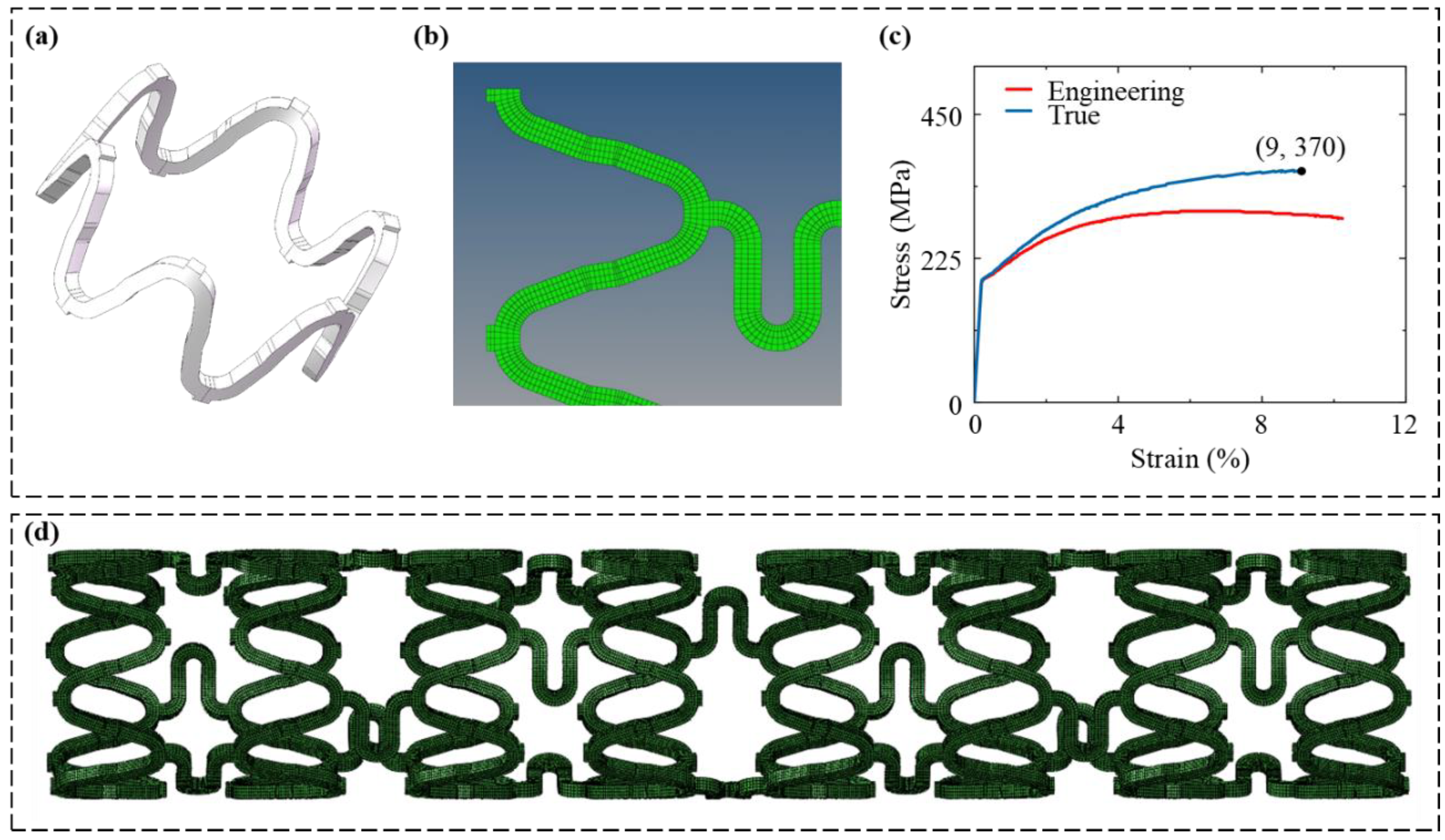
2.2. Geometry Model of Stent

The planar model of the vascular stent is drawn using Solidworks (2023, Dassault Systèmes, Waltham, MA, USA) software. The mesh division and mesh biasing operations are completed in Hypermesh (2021.2, Altair Engineering Inc., Troy, MI, USA), as illustrated in Figure 1b,d. Subsequently, the mesh model is imported into Abaqus, and the annular bending is performed using the WrapMesh (2023) plugin. The three-dimensional model of the stent, as shown in Figure 1d, has a length of 15 mm, an outer diameter of 3 mm, and a wall thickness of 160 μm. In the mechanical performance analysis, the stent undergoes significant plastic deformation, necessitating the simulation software to accurately handle large deformation nonlinear problems. Therefore, the static analysis module of Abaqus/Standard (Dassault Systèmes Simulia Corp., Johnston, RI, USA) is employed for the simulations in this study.

2.3. Material Properties

The WE43 magnesium alloy (3.94 wt% Y, 1.47 wt% Gd, 2.33 wt% Nd, and 0.52 wt% Zr) [43] is selected as the fabrication material of the stent. The density of the WE43 magnesium alloy is 1.84 × 10³ kg/m3, the Young’s modulus is 45 GPa, the Poisson’s ratio is 0.35, and the yield strength is 199 MPa [44]. The engineering stress–strain curve of the WE43 magnesium alloy is depicted as the red line in Figure 1c. However, engineering stress–strain curves do not accurately descript the true mechanical properties of the materials. Consequently, it is necessary to derive the true stress–strain curves for magnesium alloys. The detailed derivation process can be found in the Supplementary Materials (S1–S9).
Following the derivation process in the appendix, the constitutive model of the WE43 magnesium alloy is established. The transformed true stress–strain curve for the magnesium alloy is represented by the blue line in Figure 1c, from which the ultimate tensile strength of 370 MPa is obtained.

2.4. Meshing

In the finite element model of vascular stents, the commonly selected mesh types are the four-node shell element and the hexahedral element [45]. Four-node shell elements are used for simulating thin-shell problems, while hexahedral elements are widely applied to handle orthogonal structures. In this study, both the expansion shell and crimping shell, as well as the rigid platen, utilize the rigid four-node shell element S4R for meshing. For the vascular stent, which often has a periodically repeating structure, the hexahedral C3D8R mesh is employed to enhance the precision and efficiency of the calculations. The magnesium alloy stent elements have a size of 40 μm, with a total of 111,744 elements, using a 4 × 4 division method for meshing.

2.5. Boundary Conditions and Load Settings

2.5.1. Crimping and Expansion Process

After the biodegradable magnesium stent is delivered to the lesion, the radial displacement, or the vessel position, it radially expands under balloon action, undergoing plastic deformation to support the diseased vessel. The magnesium alloy is fragile during the crimping and expansion. Therefore, it is crucial to simulate this process. During the stent crimping and expansion process, the constraints and loads on the stent model must be properly set. The crimping-expansion process of the stent consists of four stages. The values of the loads in the process is according to the ISO 25539-2:2020 and the Chinese standard YY/T 0693-2008, with corresponding load applications as follows:
(1)
Crimping: The radial displacement load is applied to the crimping shell, compressing the stent from an outer diameter of 3 mm to 2 mm. Constraints are applied to the crimping shell to prevent rigid body displacement and rotation, allowing only radial deformation.
(2)
Recoil: Set the radial displacement load of the crimping shell to x = 0 mm, allowing the stent to elastically recover, and the crimping shell returns to its initial position.
(3)
Expansion: The radial displacement load is applied to the expansion shell, expanding the stent from an outer diameter of 2 mm to 4 mm. The constraints are similar to those during the crimping process, and the contact elements between the crimping shell and the outer surface of the stent are deactivated.
(4)
Expansion unloading: Set the radial displacement load of the expansion shell to x = 0 mm, allowing the stent to elastically recover.

2.5.2. Radial Support Testing Process

After crimping and expansion, the stent undergoes plastic deformation, followed by radial support force testing. During the complete compression process of the stent, the stent model must be correctly constrained and loaded. It is essential to ensure that during the radial support force testing, the cross-sectional shape of the stent changes without any slippage or displacement in other directions. To simulate the actual compression process of the stent, a smooth hard contact between the stent and the plate is set, with a penalty function of 0.2 to constrain the stent. The applied loads simulating the radial support performance of the stent are as follows:
(1)
Planar compression: The radial displacement is applied to 12 planar compression plates, crimping the magnesium alloy vascular stent to 2 mm [46]. The rigid body displacements and rotations of the planar compression plates are constrained in all directions except for the radial direction, thus allowing only the radial displacement loads. Circumferential constraints are applied at both ends of the stent to prevent rotation, and axial constraints are applied at the center of the stent to prevent axial rigid body displacement.
(2)
Planar compression unloading: The radial displacement load r = 0 mm is applied to the planar compression plates to allow the elastic recovery of the stent while the planar compression plates return to their initial positions.

2.5.3. Flexibility Analysis Process

In the FEA model, bending moments are directly applied to both ends of the stent. Initially, rigid control points are established at the axial positions of both ends of the stent in order to facilitate the application of uniform bending moments. The degrees of freedom of the rigid control points and the nodes at the stent ends are coupled, respectively. Simultaneously, a vertical direction bending moment M must be applied to the control points, where the magnitude of the moments is equal but in opposite directions. To prevent translational and rotational movements of the model, the degrees of freedom at the control points need to be constrained.

2.5.4. Fatigue Performance Process

After crimping and expansion, the stent undergoes plastic deformation, followed by fatigue performance testing. A cylindrical tube is used to simulate a real blood vessel, and a cyclic pressure load is applied to the simplified vascular model. The pressure values range from 0.0107 MPa to 0.0203 MPa, simulating the extreme values of blood pressure that the stent would encounter, corresponding to a patient diastolic pressure of 80 mmHg and a systolic pressure of 160 mmHg [47]. This value corresponds to the typical blood pressure range of a stage 2 hypertensive patient, indicating a relatively high pressure. The fatigue performance analysis involves repeatedly applying pulsatile cyclic loads to evaluate the stent’s durability under these conditions.

3. Analysis of the Mechanical Properties of the Stent

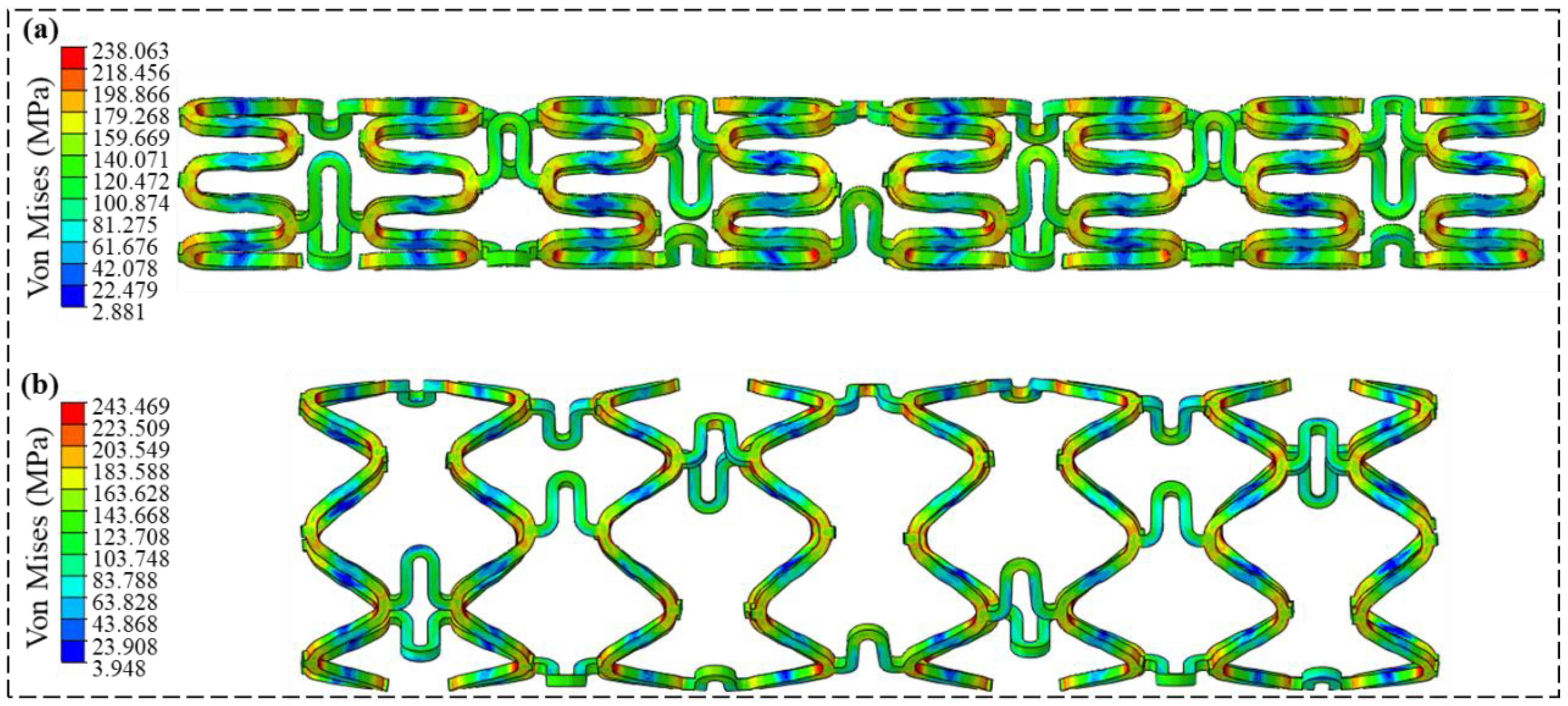
3.1. Crimping and Expansion Analysis

In the crimped and expanded states, the stent initially undergoes elastic deformation before transitioning to plastic deformation. The corresponding equivalent stress contour maps are shown in Figure 2a,b, respectively. The design of the sinusoidal support rings and the arc-shaped connecting struts ensures that the stent body can deform uniformly without interference, thereby guaranteeing the feasibility of the stent during the implantation process. In the sinusoidal wave support ring at phase zero and the bridge position, the maximum equivalent stress is less than 120 MPa. The maximum equivalent stress in the bent sections of the support ring ranges between 185 MPa and 243.5 MPa, which is only 50–66% of the magnesium alloy’s ultimate tensile strength (370 MPa). For the crimping process, the maximum equivalent stress is 238.1 MPa. Correspondingly, the maximum equivalent stress during the expansion process is 243.5 MPa.
The equivalent stresses during the crimping and expansion processes are both below the ultimate tensile strength of the magnesium alloy material, which is 370 MPa. This effectively prevents the structural failure of the stent due to stress concentration. It is primarily attributed to the micro-protrusion structure of the support rings, which effectively reduces stress concentration, thereby preventing structural failure. Additionally, both the axial shortening ratio and radial elongation rate during crimping and expansion are low, thus meeting the practical requirements for stent use. Compared to the advanced reported magnesium alloy stents, the stent designed in this study exhibits superior crimping and expansion performance [45,48]. Specifically, the described stent tends to fracture during expansion to 4 mm, whereas the stent designed in this study continues to function normally under the same conditions.

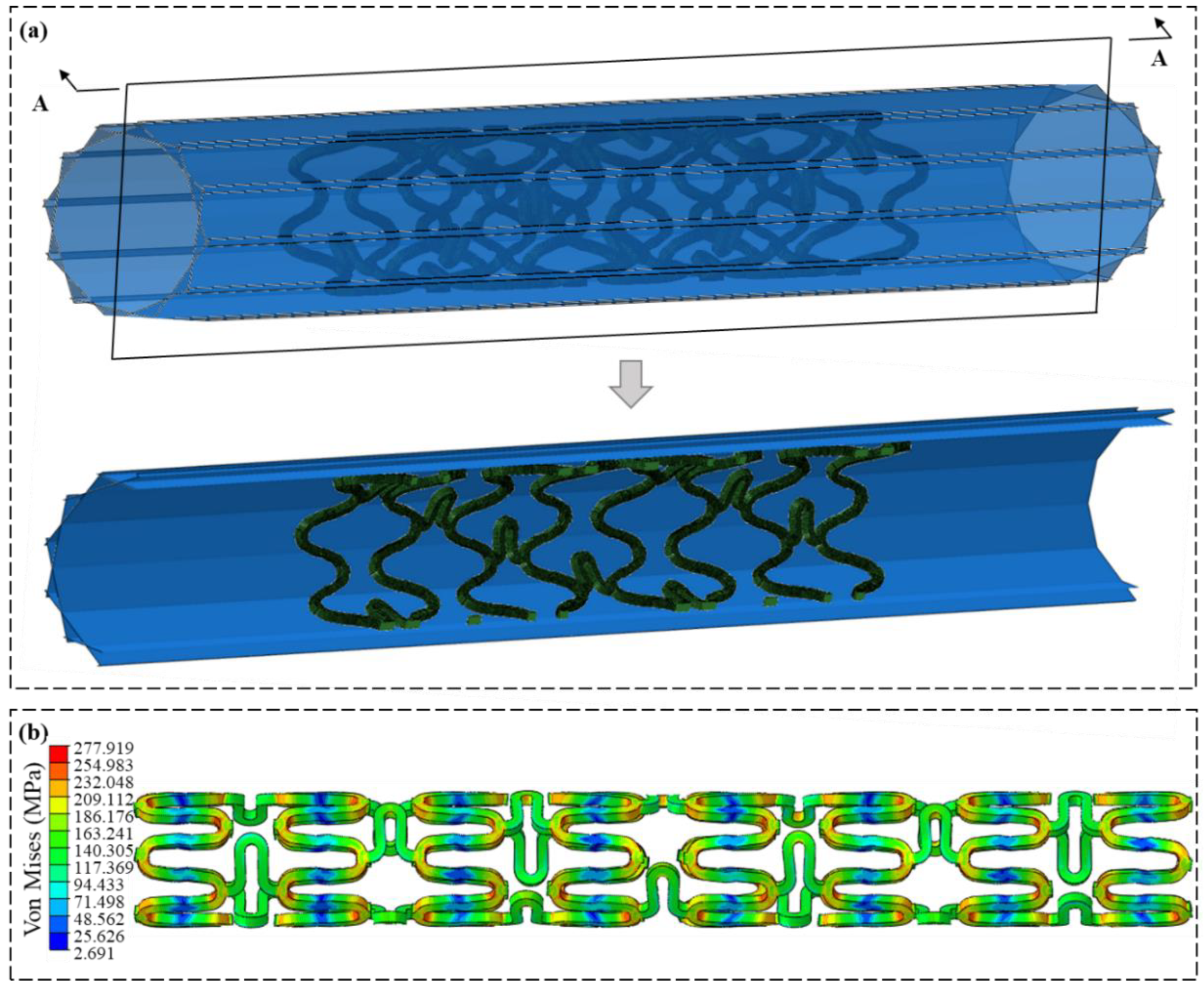
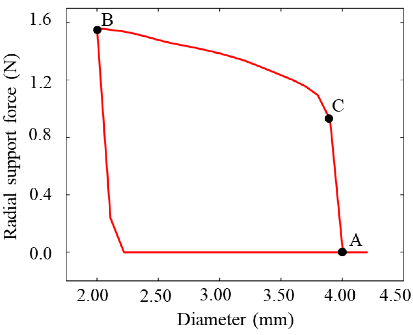
3.2. Radial Support Analysis

Radial support performance is a critical mechanical property of vascular stents, as the strength of radial support directly influences the effectiveness of vessel remodeling post-stent implantation. Currently, there is no unified testing standard for the radial support performance of vascular stents. Kwiecinski et al. employed a planar compression testing method to investigate the mechanical performance of stents under radial loading. Consequently, this study utilizes a planar compression method in simulations to accurately extract the radial support performance [49]. Common testing methods include the planar compression test and the radial compression test. This study employs the radial compression method, where the characteristic parameter is the radial support force. To quantify the radial support performance of the stent, the radial support force is normalized to the radial support strength Pload, expressed as follows:
P L o a d = F L c r i m p
where F represents the radial support force and Lcrimp denotes the radial compression distance.
To obtain the radial support force, 12 rigid planar compression plates are added to stent geometric model, as shown in Figure 3a. The interaction between the stent and the plates is modeled as smooth hard contact, with the penalty function set to 0.2 to constrain the stent. After the stent is crimped and expanded, the radial displacement load is applied to the rigid planar compression plates, compressing the stent to the diameter of 2 mm. Figure 3b shows the stress contour map from the planar compression plate test, where the maximum equivalent stress in the stent during this test is 277.9 MPa, which is below the fracture stress of 370 MPa for the WE43 magnesium alloy.
The relationship between the stent’s radial support force and its diameter is depicted in Figure 4. In the initial phase of compression (A–C), the radial support force and diameter exhibit a linear relationship. During this process, the stent undergoes only elastic deformation. As the compression distance of the rigid plates is increased further (C–B), the stent undergoes plastic deformation, and the relationship between the support force and diameter becomes nonlinear. As shown in Figure 4, the maximum radial support force provided by the stent is 1.56 N. Substituting this value into Equation (1), the radial support strength of the stent after undergoing crimping and expansion is calculated to be 780 mN/mm. The advanced reported stent structure has a radial support strength of 692 mN/mm and a radial support force of 1.06 N. The stent designed in this study demonstrates a performance improvement of 13% and 47%, respectively [45,48].

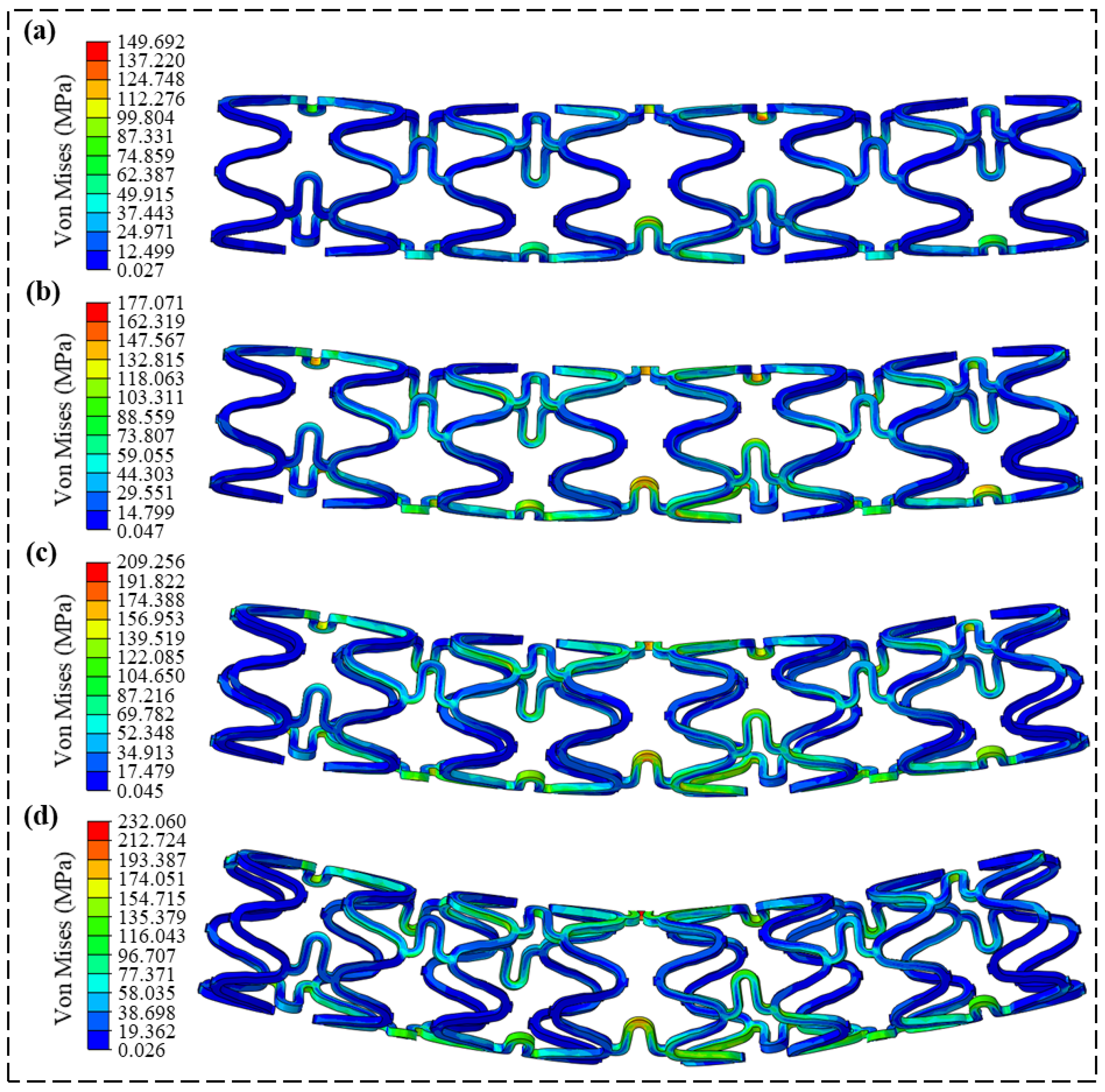
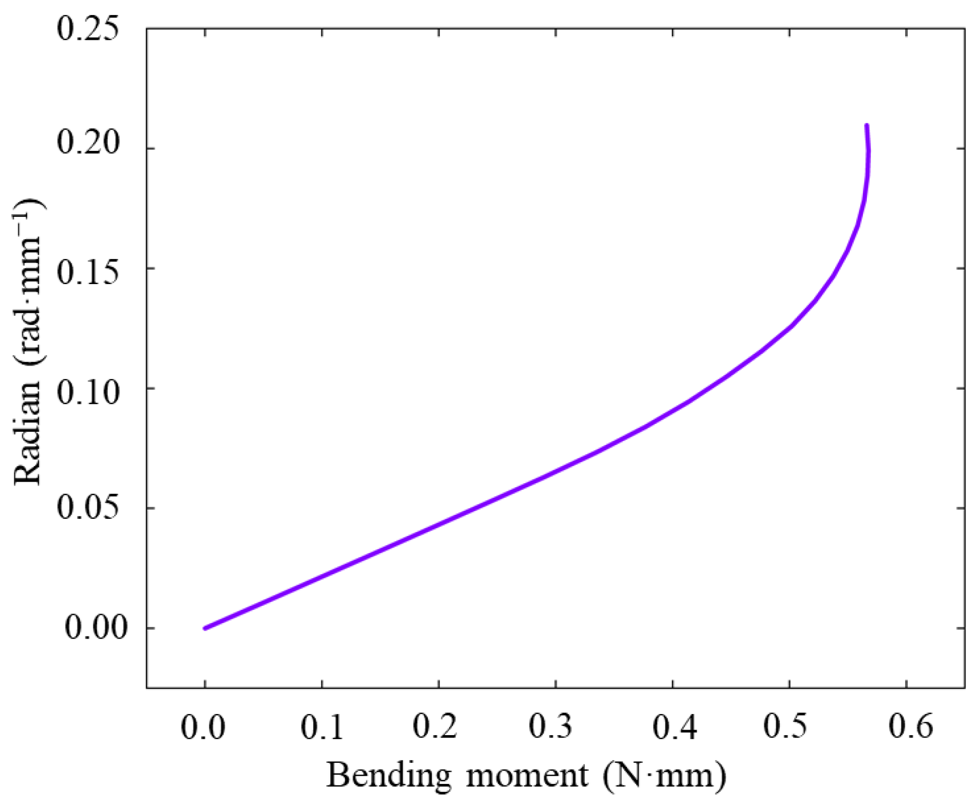
3.3. Flexibility Analysis

Flexibility determines whether a stent can smoothly enter a lesioned area of a vessel post-crimping. Bending stiffness is commonly utilized to quantify flexibility. The prevalent testing methods include the three-point bending test and the direct application of bending moments at both ends of the stent. The method of applying bending moments at both ends allows for the uniform distribution of the moment across the stent, and is extensively used in FEA. Bending stiffness is defined as follows:
E I = M 2 φ / L
where EI represents the bending stiffness, M is the bending moment applied at the ends of the stent, φ is the deflection angle of the stent, L denotes the length of the stent, and 2φ/L represents the angle of rotation per unit length of the stent.
In the FEA model, the bending moments are directly applied to both ends of the stent. Initially, rigid control points are established at the axial positions of both ends of the stent to facilitate the application of uniform bending moments. The degrees of freedom of the rigid control points and the nodes at the stent ends are coupled, respectively. Simultaneously, a vertical direction bending moment M must be applied to the control points, where the magnitude of the moments is equal but acts in opposite directions. To prevent translational and rotational movements of the model, the degrees of freedom at the control points need to be constrained.
The deflection angle φ represents the angle between the central axes of the bracket before and after the application of the moment M. The flexibility within a bending angle range of 0°–12° is analyzed, with the equivalent stress distributions at 3°, 6°, 9°, and 12° shown in Figure 5a–d. The analysis reveals that the maximum equivalent stress during bending is 232.1 MPa, which is below the ultimate tensile strength (370 MPa) of the WE43 magnesium alloy, indicating that no fracture occurs during the bending process. The relationship between the stent bending angle and bending moment is illustrated in Figure 6. By calculating the initial slope of the deformation curve, the bending stiffness is determined to be 4.31 N·mm2. This value is slightly higher than the bending stiffness of the commercial Absorb GT 1 polymer stent, which is 4.20 N·mm2 [50].
Compared to the advanced reported U.S. patented structure, which has bending stiffness values of 60.1 N·mm2 and 42.1 N·mm2, the bending stiffness of the stent designed in this study is improved by a factor of 13.9 and 9.76, respectively. This reduction ensures that the stent can navigate through complex vasculature during implantation [45,48]. As indicated in Figure 6, the bending moment of the stent linearly increases with the bending angle from 0° to 9°. When the bending angle increases to the range of 9° to 12°, the bending moment no longer changes. At this stage, the stent undergoes additional plastic deformation during the implantation process, which affects its biomechanical performance. Therefore, the recommended bending angle for this stent should be within 10°.

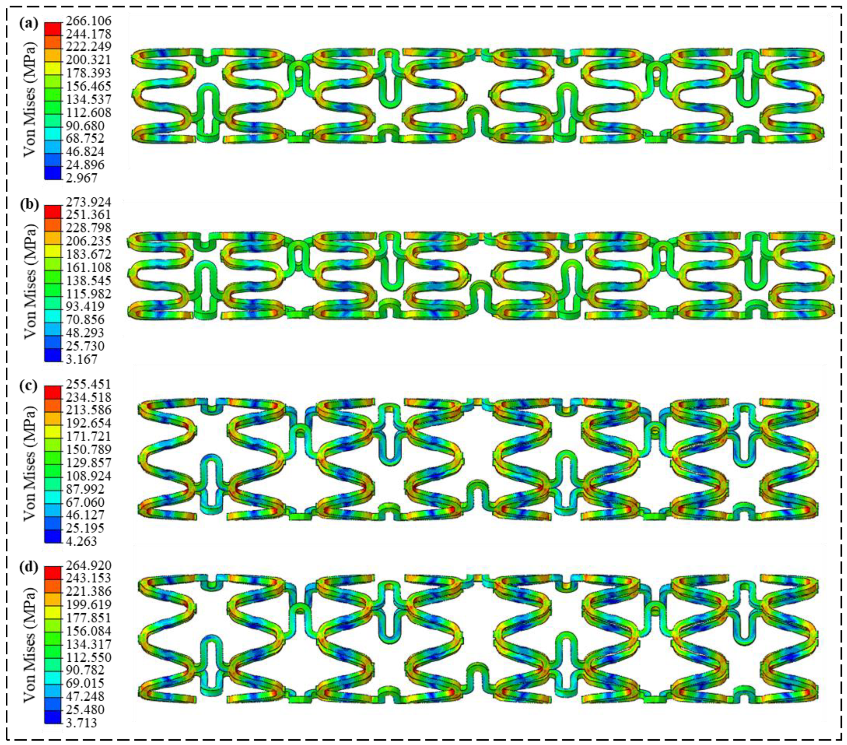
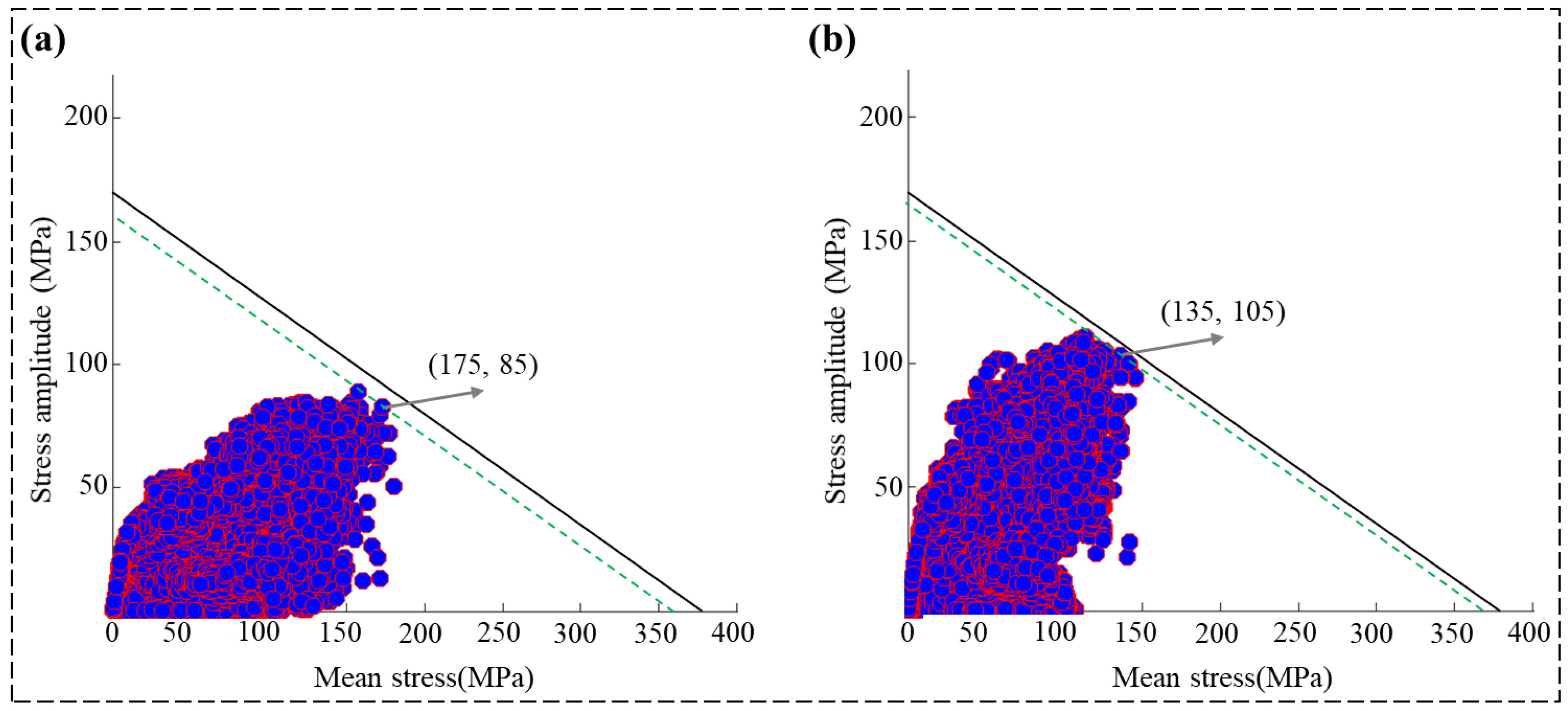
3.4. Fatigue Performance Analysis

Vascular stents must endure long-term vascular pressures and dynamic blood forces in the body without fracturing. Therefore, fatigue analysis is an indispensable part of the design and evaluation process for vascular stents. In the fatigue analysis of cardiovascular stents, the Goodman fatigue analysis method is an effective tool [51]. In this study, the fatigue performance of the stent is assessed using the Goodman diagram method recommended by the U.S. FDA, following the formula described below:
σ a = σ e ( 1 σ m σ b )
σ a = ( σ s y s t o l i c σ d i a s t o l i c ) 2
σ m = ( σ s y s t o l i c + σ d i a s t o l i c ) 2
where σa represents the stress amplitude and is half the difference between the maximum and minimum stresses during cyclic loading, and σm represents the mean stress and is half the sum of the maximum and minimum stresses. The ultimate tensile strength is denoted as σb, and the fatigue limit stress of the material is σe. The stresses σsystolic and σdiastolic correspond to the stent stresses under systolic (0.0203 MPa) and diastolic (0.0107 MPa) pressures, respectively.
If the fatigue limit stress σe and the ultimate tensile strength σb are known, connecting the points (0, σe) and (σb, 0) provides the limit stress line. By extracting the stress values at all nodes of the stent at the end of the diastolic and systolic phases, and calculating the mean stress and stress amplitude, the Goodman distribution for the stent’s fatigue performance is obtained. If the stress values lie above the limit stress line, it indicates the fatigue failure of the stent. Conversely, stress values below this line imply that the stent meets the application standards.
As shown in Figure 7, under cyclic pressure loads of 0.0107 MPa and 0.0203 MPa, the maximum equivalent stresses before and after stent expansion are 266.1 MPa, 273.9 MPa, 255.5 MPa, and 264.9 MPa, respectively. All these values are below the ultimate tensile strength (370 MPa) of the WE43 magnesium alloy. In the regions of the support rings and connecting struts, the average stress ranges from 150 MPa to 200 MPa, with the mean stress between them being less than 150 MPa. Only at the crest of the sinusoidal waves, the average stresses are greater than 250 MPa. The results demonstrate that the introduction of micro-protrusion structures effectively reduces stress concentration in the stent.
Based on the fatigue analysis results presented in Figure 7, the minimum and maximum equivalent stresses for the 3 mm stent are 2.967 MPa and 273.924 MPa, respectively, while for the 4 mm expanded stent, the minimum and maximum equivalent stresses are 3.713 MPa and 264.920 MPa, respectively. By locating these corresponding points on the stress–strain curve depicted in Figure 1c, the total strain during the simulation process is estimated to be approximately 1.4%. According to the experimental results reported in reference [43], the fatigue limit of the T6-treated WE43 magnesium alloy decreases to 170 MPa at a total strain of 1.4% (for 1000 cycles). Throughout the reduction in the fatigue limit, the stent undergoes both elastic and plastic deformation. During this period, the plastic strain amplitude in the T6 magnesium alloy gradually increases, exhibiting plastic softening. This plastic softening reduces the extent of plastic deformation that the material undergoes, thereby resulting in a lower overall fatigue damage.
Figure 8 shows the Goodman fatigue distribution, where all node stresses on the stent are below the limit stress line, satisfying the fatigue performance requirements. Furthermore, the dynamic safety factor is used to quantify the fatigue performance. The safety factor is described as follows:
1 S F d y n a m i c = σ m σ b + σ a σ e
where SFdynamic is the dynamic safety factor. In the context of analyzing the fatigue performance of degradable magnesium alloys under finite element analysis, points σm and σa represent the equivalent stress amplitude and mean equivalent stress of the stent under pulsatile blood flow loading. By applying the parallel line method on the limit stress line depicted in Figure 8, the points (175, 85) and (135, 105) are identified. Substituting these values into Equation (6), the safety factors SFdynamic are calculated to be 1.03 and 1.02, respectively.
The calculations indicate that the initial safety factor of the stent is 1.03, and the safety factor after expansion is 1.02. Both values satisfy the requirements for stent fatigue life usage, as they are greater than 1. These results indicate that both the initial state stent and the crimped-expanded stent do not experience fatigue failure after undergoing multiple cyclic pressure loads. This ensures that the stent can provide long-term effective support for the diseased vessel after implantation.

4. Conclusions

In this study, a magnesium alloy biodegradable stent based on a micro-protrusion structure is designed. To evaluate the quality of the designed stent, FEA is employed to assess its mechanical performance from the following four aspects: crimping and expansion, radial support force, flexibility, and fatigue resistance. The mechanical performance analysis results indicate that the maximum equivalent stress in all four aspects is below the ultimate tensile strength of the WE43 magnesium alloy. The radial support performance analysis results show that the radial support strength and radial support force are 780 mN/mm and 1.56 N, respectively. When compared to the advanced reported stent structure, these values represent improvements of 13% and 47%, respectively. Flexibility analysis results suggest that the recommended bending angle for the design of the stent should be within 10 degrees. Additionally, the stent’s bending height can reach 4.31 N·mm2, and its flexibility is enhanced by a factor of 9.76. This ensures that the stent possesses the capability to navigate through complex vasculature during implantation. Fatigue analysis indicates that the initial safety factor of the stent is as high as 1.03, and after expansion, it is 1.02, both exceeding the minimum allowable safety factor of 1. The results indicate that the magnesium alloy stent with micro-protrusion structures exhibits superior mechanical performance.

Supplementary Materials

The following supporting information can be downloaded at: https://www.mdpi.com/article/10.3390/met14060704/s1, Equations (S1)–(S9).

Author Contributions

Conceptualization, F.D. and S.L.; methodology, F.D. and S.L.; software, J.C.; validation, J.C., F.D. and S.L.; formal analysis, J.C.; investigation, J.C.; resources, J.C.; data curation, J.C.; writing—original draft preparation, J.C.; writing—review and editing, J.C. and F.D.; visualization, J.C.; supervision, F.D. and S.L.; project administration, S.L.; funding acquisition, F.D. and S.L. All authors have read and agreed to the published version of the manuscript.

Funding

This research received no external funding.

Data Availability Statement

The original contributions presented in the study are included in the article, further inquiries can be directed to the corresponding author.

Conflicts of Interest

The authors declare no conflict of interest.

References

  1. Naghavi, M.; Wang, H.; Lozano, R.; Davis, A.; Liang, X.; Zhou, M.; Vollset, S.E.; Ozgoren, A.A.; Abdalla, S.; Abd Allah, F.; et al. Global, regional, and national age-sex specific all-cause and cause-specific mortality for 240 causes of death, 1990–2013: A systematic analysis for the global burden of disease study 2013. Lancet 2015, 385, 117–171. [Google Scholar]
  2. Roth, G.A.; Forouzanfar, M.H.; Moran, A.E.; Barber, R.; Nguyen, G.; Feigin, V.L.; Naghavi, M.; Mensah, G.A.; Murray, C.J. Demographic and epidemiologic drivers of global cardiovascular mortality. N. Engl. J. Med. 2015, 372, 1333–1341. [Google Scholar] [CrossRef]
  3. Aldea, G.S.; Bakaeen, F.G.; Pal, J.; Fremes, S.; Head, S.J.; Sabik, J.; Rosengart, T.; Kappetein, A.P.; Thourani, V.H.; Firestone, S.; et al. The society of thoracic surgeons clinical practice guidelines on arterial conduits for coronary artery bypass grafting. Ann. Thorac. Surg. 2016, 101, 801–809. [Google Scholar] [CrossRef]
  4. Gaudino, M.; Benedetto, U.; Fremes, S.; Biondi-Zoccai, G.; Sedrakyan, A.; Puskas, J.D.; Angelini, G.D.; Buxton, B.; Frati, G.; Hare, D.L.; et al. Radial-artery or saphenous-vein grafts in coronary-artery bypass surgery. N. Engl. J. Med. 2018, 378, 2069–2077. [Google Scholar] [CrossRef] [PubMed]
  5. Mäkikallio, T.; Holm, N.R.; Lindsay, M.; Spence, M.S.; Erglis, A.; Menown, I.B.A.; Trovik, T.; Eskola, M.; Romppanen, H.; Kellerth, T.; et al. Percutaneous coronary angioplasty versus coronary artery bypass grafting in treatment of unprotected left main stenosis (NOBLE): A prospective, randomised, open-label, non-inferiority trial. Lancet 2017, 389, 1102. [Google Scholar] [CrossRef] [PubMed]
  6. Bønaa, K.H.; Mannsverk, J.; Wiseth, R.; Aaberge, L.; Myreng, Y.; Nygård, O.; Nilsen, D.W.; Kløw, N.-E.; Uchto, M.; Trovik, T.; et al. Drug-eluting or Bare-metal stents for coronary artery disease. N. Engl. J. Med. 2016, 375, 1242–1252. [Google Scholar] [CrossRef] [PubMed]
  7. Stefanini, G.G.; Holmes, D.R., Jr. Drug-eluting coronary-artery stents. N. Engl. J. Med. 2013, 368, 254–265. [Google Scholar] [CrossRef]
  8. Köster, R.; Vieluf, D.; Kiehn, M.; Sommerauer, M.; Kähler, J.; Baldus, S.; Meinertz, T.; Hamm, C.W. Nickel and molybdenum contact allergies in patients with coronary in-stent restenosis. Lancet 2000, 356, 1895–1897. [Google Scholar] [CrossRef] [PubMed]
  9. McGuigan, A.P.; Sefton, M.V. The influence of biomaterials on endothelial cell thrombogenicity. Biomaterials 2007, 28, 2547–2571. [Google Scholar] [CrossRef]
  10. Scott, N.A. Restenosis following implantation of bare metal coronary stents: Pathophysiology and pathways involved in the vascular response to injury. Adv. Drug Deliv. Rev. 2006, 58, 358–376. [Google Scholar] [CrossRef]
  11. Welt, F.G.P.; Rogers, C. Inflammation and restenosis in the stent era. Arterioscler. Thromb. Vasc. Biol. 2002, 22, 1769–1776. [Google Scholar] [CrossRef]
  12. Boland, E.L.; Shine, C.J.; Kelly, N.; Sweeney, C.A.; McHugh, P.E. A Review of Material Degradation Modelling for the Analysis and Design of Bioabsorbable Stents. Ann. Biomed. Eng. 2015, 44, 341–356. [Google Scholar] [CrossRef]
  13. Gogas, B.D. Bioresorbable scaffolds for percutaneous coronary interventions. Glob. Cardiol. Sci. Pract. 2015, 2014, 409–427. [Google Scholar] [CrossRef] [PubMed]
  14. Wiebe, J.; Nef, H.M.; Hamm, C.W. Current Status of Bioresorbable Scaffolds in the Treatment of Coronary Artery Disease. J. Am. Coll. Circardiol. 2014, 64, 2541–2551. [Google Scholar] [CrossRef]
  15. Hubbert, L.; Baranowski, J.; Delshad, B.; Ahn, H. Left Atrial Pressure Monitoring with an Implantable Wireless Pressure Sensor After Implantation of a Left Ventricular Assist Device. ASAIO J. 2017, 63, e60–e65. [Google Scholar] [CrossRef]
  16. Raj, L.M.; Saxon, L.A. Haemodynamic monitoring devices in heart failure: Maximising benefit with digitally enabled patient centric care. Arrhythmia Electrophysiol. Rev. 2018, 7, 294–298. [Google Scholar] [CrossRef] [PubMed]
  17. Schmier, J.K.; Ong, K.L.; Fonarow, G.C. Cost-effectiveness of remote cardiac monitoring with the cardiomems heart failure sys-tem. Clin. Cardiol. 2017, 40, 430–436. [Google Scholar] [CrossRef] [PubMed]
  18. Chen, Y.; Xu, Z.; Smith, C.; Sankar, J. Recent advances on the development of magnesium alloys for biodegradable implants. Acta Biomater. 2014, 10, 4561–4573. [Google Scholar] [CrossRef] [PubMed]
  19. Hermawan, H.; Dube, D.; Mantovani, D. Developments in metallic biodegradable stents. Acta Biomater. 2010, 6, 1693–1697. [Google Scholar] [CrossRef]
  20. Niklason, L.; Dai, G.H. Arterial venous differentiation for vascular bioengineering. Annu. Rev. Biomed. Eng. 2018, 20, 431–447. [Google Scholar] [CrossRef]
  21. Iqbal, J.; Onuma, Y.; Ormiston, J.; Abizaid, A.; Waksman, R.; Serruys, P. Bioresorbable scaffolds: Rationale, current status, challenges, and future. Eur. Heart J. 2013, 35, 765–776. [Google Scholar] [CrossRef]
  22. Yamaji, K.; Ueki, Y.; Souteyrand, G.; Daemen, J.; Wiebe, J.; Nef, H.; Adriaenssens, T.; Loh, J.P.; Lattuca, B.; Wykrzykowska, J.J.; et al. Mechanisms of very late bioresorbable scaffold thrombosis the invest registry. J. Am. Coll. Cardiol. 2017, 70, 2330–2344. [Google Scholar] [CrossRef]
  23. Jinnouchi, H.; Torii, S.; Sakamoto, A.; Kolodgie, F.D.; Virmani, R.; Finn, A.V. Fully bioresorbable vascular scaffolds: Lessons learned and future directions. Nat. Rev. Cardiol. 2019, 16, 286–304. [Google Scholar] [CrossRef]
  24. Wang, P.J.; Ferralis, N.; Conway, C.; Grossman, J.C.; Edelman, E.R. Strain-induced accelerated asymmetric spatial degradation of polymeric vascular scaffolds. Proc. Natl. Acad. Sci. USA 2018, 115, 2640–2645. [Google Scholar] [CrossRef] [PubMed]
  25. Wang, P.J.; Nezami, F.R.; Gorji, M.B.; Berti, F.; Petrini, L.; Wierzbicki, T.; Migliavacca, F.; Edelman, E.R. Effect of working environment and procedural strategies on mechanical performance of bioresorbable vascular scaffolds. Acta Biomater. 2018, 82, 34–43. [Google Scholar] [CrossRef] [PubMed]
  26. Bowen, P.K.; Shearier, E.R.; Zhao, S.; Guillory, R.J., 2nd; Zhao, F.; Goldman, J.; Drelich, J.W. Biodegradable Metals for Cardiovascular Stents: From Clinical Concerns to Recent Zn-Alloys. Adv. Healthc. Mater. 2016, 5, 1121–1140. [Google Scholar] [CrossRef] [PubMed]
  27. Zheng, Y.F.; Gu, X.N.; Witte, F. Biodegradable metals. Mater. Sci. Eng. R Rep. 2014, 77, 1–34. [Google Scholar] [CrossRef]
  28. Mao, L.; Shen, L.; Chen, J.H.; Wu, Y.; Kwak, M.; Lu, Y.; Xue, Q.; Pei, J.; Zhang, L.; Yuan, G.; et al. Enhanced bioactivity of Mg-Nd-Zn-Zr alloy achieved with nanoscale MgF2 surface for vascular stent application. ACS Appl. Mater. Interfaces 2015, 7, 5320–5330. [Google Scholar] [CrossRef]
  29. Mao, L.; Shen, L.; Niu, J.; Zhang, J.; Ding, W.; Wu, Y.; Fan, R.; Yuan, G. Nanophasic biodegradation enhances the durability and biocompatibility of magnesium alloys for the next-generation vascular stents. Nanoscale 2013, 5, 9517–9522. [Google Scholar] [CrossRef]
  30. Heublein, B.; Rohde, R.; Kaese, V.; Niemeyer, M.; Hartung, W.; Haverich, A. Biocorrosion of magnesium alloys: A new principle in cardiovascular implant technology? Heart 2003, 89, 651–656. [Google Scholar] [CrossRef]
  31. DI Mario, C.; Griffiths, H.; Goktekin, O.; Peeters, N.; Verbist, J.; Bosiers, M.; Deloose, K.; Heublein, B.; Rohde, R.; Kasese, V.; et al. Drug-Eluting Bioabsorbable Magnesium Stent. J. Interv. Cardiol. 2004, 17, 391–395. [Google Scholar] [CrossRef]
  32. Waksman, R.; Pakala, R.; Kuchulakanti, P.K.; Baffour, R.; Hellinga, D.; Seabron, R.; Tio, F.O.; Wittchow, E.; Hartwig, S.; Harder, C.; et al. Safety and efficacy of bioabsorbable magnesium alloy stents in porcine coronary arteries. Catheter. Cardiovasc. Interv. 2006, 68, 607–617. [Google Scholar] [CrossRef] [PubMed]
  33. Erbel, R.; Di Mario, C.; Bartunek, J.; Bonnier, J.; de Bruyne, B.; Eberli, F.R.; Erne, P.; Haude, M.; Heublein, B.; Horrigan, M.; et al. Temporary scaffolding of coronary arteries with bioabsorbable magnesium stents: A prospective, non-randomised multicentre trial. Lancet 2007, 369, 1869–1875. [Google Scholar] [CrossRef]
  34. Haude, M.; Erbel, R.; Erne, P.; Verheye, S.; Degen, H.; Böse, D.; Vermeersch, P.; Wijnbergen, I.; Weissman, N.; Prati, F.; et al. Safety and performance of the drug-eluting absorbable metal scaffold (DREAMS) in patients with de-novo coronary lesions: 12 month results of the prospective, multicentre, first-in-man BIOSOLVE-I trial. Lancet 2013, 381, 836–844. [Google Scholar] [CrossRef]
  35. Peeters, P.; Bosiers, M.; Verbist, J.; Deloose, K.; Heublein, B. Preliminary Results After Application of Absorbable Metal Stents in Patients with Critical Limb Ischemia. J. Endovasc. Ther. 2005, 12, 1–5. [Google Scholar] [CrossRef] [PubMed]
  36. Waksman, R.; Erbel, R.; Di Mario, C.; Bartunek, J.; de Bruyne, B.; Eberli, F.R.; Erne, P.; Haude, M.; Horrigan, M.; Ilsley, C.; et al. Early- and long-term intravascular ultrasound and angiographic findings after bioab-sorbable magnesium stent implantation in human coronary arteries. JACC Cardiovasc. Interv. 2009, 2, 312–320. [Google Scholar] [CrossRef] [PubMed]
  37. Gomez-Lara, J.; Radu, M.; Brugaletta, S.; Farooq, V.; Diletti, R.; Onuma, Y.; Windecker, S.; Thuesen, L.; McClean, D.; Koolen, J.; et al. Serial Analysis of the Malapposed and Uncovered Struts of the New Generation of Everolimus-Eluting Bioresorbable Scaffold with Optical Coherence Tomography. JACC Cardiovasc. Interv. 2011, 4, 992–1001. [Google Scholar] [CrossRef] [PubMed]
  38. Li, N.; Zheng, Y.F. Novel magnesium alloys developed for biomedical application: A review. J. Mater. Sci. Technol. 2013, 29, 489–502. [Google Scholar] [CrossRef]
  39. Zhu, Y.Q.; Zhang, H.B.; Zhang, Y.R.; Wu, H.; Wei, L.; Zhou, G.; Zhang, Y.; Deng, L.; Cheng, Y.; Li, M.; et al. Endovascular metal devices for the treatment of cerebrovascular diseases. Adv. Mater. 2019, 31, 44. [Google Scholar] [CrossRef]
  40. Antoniadis, A.P.; Mortier, P.; Kassab, G.; Dubini, G.; Foin, N.; Murasato, Y.; Giannopoulos, A.A.; Tu, S.; Iwasaki, K.; Hikichi, Y.; et al. Biomechanical modeling to improve coronary artery bifurcation stenting expert review document on techniques and clinical implementation. JACC Cardiovasc. Interv. 2015, 8, 1281–1296. [Google Scholar] [CrossRef]
  41. ISO 25539-2:2020; Cardiovascular Implants—Endovascular Devices—Part 2. Vascular Stents. International Organization for Standardization (ISO): Geneva, Switzerland, 2020.
  42. YY/T 0693-2008; Passive Implants-Intravascular Catheters. National Medical Products Administration (NMPA): Beijing, China, 2008.
  43. Cai, Y.; Wei, J.; Yan, H.; Chen, Y.; Chen, R. Low-cycle fatigue behavior of solutionized and aged WE43 magnesium alloys at room temperature. J. Magnes. Alloys, 2022; in press. [Google Scholar] [CrossRef]
  44. Kubásek, J.; Dvorský, D.; Čavojský, M.; Roudnická, M.; Vojtech, D. WE43 magnesium alloy-material for challenging applications. Met. Mater. 2019, 57, 159–165. [Google Scholar] [CrossRef]
  45. Wang, Q.; Fang, G.; Zhao, Y.H.; Zhou, J. Improvement of mechanical performance of bioresorbable magnesium alloy coronary artery stents through stent pattern redesign. Appl. Sci. 2018, 8, 22. [Google Scholar] [CrossRef]
  46. Green, S.R.; Kwon, R.S.; Elta, G.H.; Gianchandani, Y.B. In vivo and in situ evaluation of a wireless magnetoelastic sensor array for plastic biliary stent monitoring. Biomed. Microdevices 2013, 15, 509–517. [Google Scholar] [CrossRef]
  47. Harvey, S.M. Nitinol Stent Fatigue in a Peripheral Human Artery Subjected to Pulsatile and Articulation Loading. J. Mater. Eng. Perform. 2011, 20, 697–705. [Google Scholar] [CrossRef]
  48. Lootz, D.; Surber, B.; Wintsch, D.; Riedmueller, J. Stent Having Radially Expandable Main Body. U.S. Patent No. 12/057,806, 25 June 2013. [Google Scholar]
  49. Kwiecinski, J.; Cheng, C.P.; Uberoi, R.; Hadi, M.; Hempel, P.; Degel, C.; You, Z. Thoracic aortic parallel stent-graft behaviour when subjected to radial loading. J. Mech. Behav. Biomed. Mater. 2021, 118, 104407. [Google Scholar] [CrossRef]
  50. Schmidt, W.; Behrens, P.; Brandt-Wunderlich, C.; Siewert, S.; Grabow, N.; Schmitz, K.-P. In vitro performance investigation of bioresorbable scaffolds—Standard tests for vascular stents and beyond. Cardiovasc. Revasc. Med. 2016, 17, 375–383. [Google Scholar] [CrossRef]
  51. US Food and Drug Administration. Non-Clinical Engineering Tests and Recommended Labeling for Intravascular Stents and Associated Delivery Systems: Guidance for Industry and FDA Staff; US Department of Health and Human Services, Food and Drug Administration, Centre for Devices and Radiological Health: Silver Spring, MD, USA, 2010.
Figure 1. Vascular stent modeling. (a) support ring model; (b) mesh delineation; (c) real and engineering stress–strain curves for WE43 magnesium alloys; (d) mesh model of the initial state of the stent.
Metals 14 00704 g001
Figure 2. Mises stress contour map of the stent. (a) Contour map of the crimping process; (b) contour map of the expansion process.
Metals 14 00704 g002
Figure 3. The process of planar compression plate test. (a) Platen stent FEA analysis model; (b) stent mises stress contour map of the radial support force.
Metals 14 00704 g003
Figure 4. Stent radial support force–diameter curves.
Metals 14 00704 g004
Figure 5. Mises stress contour map of the stent with different bending angles. (a) 3° bending angles; (b) 6° bending angles; (c) 9° bending angles; (d) 12° bending angles.
Metals 14 00704 g005
Figure 6. Stent bending moment–bending radian curve.
Metals 14 00704 g006
Figure 7. Stress contour map of the magnesium alloy vascular stent at 0.0107 MPa and 0.0203 MPa pressure. (a) 3 mm stent diameter at 0.0107 MPa pressure; (b) 3 mm stent diameter at 0.0203 MPa pressure; (c) expanded to 4 mm stent diameter stent at 0.0107 MPa pressure; (d) expanded to 4 mm diameter stent at 0.0203 MPa pressure.
Metals 14 00704 g007
Figure 8. Goodman fatigue diagrams for magnesium alloy vascular stents with different diameters. (a) 3 mm stent diameter; (b) expanded to 4 mm diameter.
Metals 14 00704 g008
Disclaimer/Publisher’s Note: The statements, opinions and data contained in all publications are solely those of the individual author(s) and contributor(s) and not of MDPI and/or the editor(s). MDPI and/or the editor(s) disclaim responsibility for any injury to people or property resulting from any ideas, methods, instructions or products referred to in the content.

