Article

On the Enhancement of Material Formability in Hybrid Wire Arc Additive Manufacturing

by
João P. M. Pragana
1,*,
Beatriz Brito
1,
Ivo M. F. Bragança
1,2,
Carlos M. A. Silva
1 and
Paulo A. F. Martins
1
1
IDMEC, Instituto Superior Técnico, Universidade de Lisboa, 1049-001 Lisbon, Portugal
2
CIMOSM, Instituto Superior de Engenharia de Lisboa, Instituto Politécnico de Lisboa, 1959-007 Lisbon, Portugal
*
Author to whom correspondence should be addressed.
Metals 2024, 14(6), 716; https://doi.org/10.3390/met14060716
Submission received: 7 May 2024 / Revised: 7 June 2024 / Accepted: 13 June 2024 / Published: 17 June 2024
(This article belongs to the Special Issue Hybrid Metal Additive Manufacturing)

Abstract

:
This paper is focused on improving material formability in hybrid wire-arc additive manufacturing comprising metal forming stages to produce small-to-medium batches of customized parts. The methodology involves fabricating wire arc additive manufactured AISI 316L stainless steel parts subjected to mechanical and thermal processing (MTP), followed by microhardness measurements, tensile testing with digital image correlation, as well as microstructure and microscopic observations. Results show that mechanical processing by pre-straining followed by thermal processing by annealing can reduce material hardness and strength, increase ductility, and eliminate anisotropy by recrystallizing the as-built dendritic-based columnar grain microstructure into an equiaxed grain microstructure.

1. Introduction

Direct energy deposition arc (DED-Arc), hereafter referred to as wire arc additive manufacturing (WAAM), is a subset of metal additive manufacturing processes, according to the ISO/ASTM 52900:2021 standard [1]. It utilizes an electric arc to provide the thermal energy necessary for melting and depositing the wire feedstock material layer by layer and shares working principles with well-established gas metal arc, gas tungsten arc, or plasma arc welding processes [2]. The industrial interest in WAAM for the creation of large-scale parts with low-to-medium quality stems from its material efficiency and high deposition rates (5–6 kg/h) compared to other metal additive manufacturing (MAM) processes based on laser or electron beam thermal heat sources [3]. The widespread availability of arc welding-based machines and motion systems in metalworking companies further contributes to the growing interest in WAAM [4].
However, despite these advantages, WAAM still needs to become a viable alternative manufacturing technology in many industries due to the difficulties associated with meeting the geometrical, surface, and metallurgical requirements of the parts. These difficulties are primarily attributed to the large melt pools created by the electric arc (thermal heat source) which give rise to differential expansion and contraction across the deposited material during the heating and cooling cycles, as well as to porosity, precipitation reactions, and formation of dendritic-based columnar grain structures [5]. Thermal residual stresses after material cooling down to ambient temperature give rise to additional distortions that further deteriorate the overall accuracy of the as-built parts [6].
Several fabrication routes centered on the hybridization of WAAM with other manufacturing technologies have been proposed in the last years to overcome the difficulties mentioned above. These routes, which are built upon concurrent or sequential integrations of WAAM with, for instance, metal cutting, are, nowadays, used to improve both geometric precision and surface quality of the as-built parts during post-processing or as coupled integrations of material deposition and layer-by-layer cutting [7]. However, these solutions are limited to small production batches and are unable to mitigate the metallurgical defects intrinsic to WAAM.
Integration with metal forming is currently regarded as one of the most promising solutions to broaden the scope of applicability of WAAM from unitary to batch production, a trend that has recently been explored with other metal additive manufacturing (MAM) processes [8]. Indeed, several publications highlight the potential of using MAM to produce preforms and near-net-shape parts in small-to-medium batch sizes through integration with well-known sheet [9], bulk [10], and sheet-bulk [11] forming processes. However, some other publications point out difficulties related to anisotropy and formability limits [12,13], caused by metallurgical phenomena that limit the applicability window of metal forming operations down to low levels of plastic deformation.
The number of studies focused on the hybridization of WAAM with metal forming is scarce and almost exclusively centered on interlayer surface rolling, peening, and ultrasonic impact to enhance the microstructure, reduce porosity, and alleviate thermal residual stresses resulting from the heating and cooling cycles of material deposition [14]. However, the effectiveness of this type of hybridization with metal forming is limited to unitary production due to significant increases in manufacturing times and energy consumption [15]. Moreover, some studies report decreases in ductility compared to the original as-built materials [16], justifying the need for novel WAAM-based hybrid manufacturing routes suitable for small and medium batch production.
This paper is focused on a novel WAAM-based hybrid manufacturing route comprising material deposition, mechanical and thermal processing (MTP), and metal forming stages (Figure 1) that was recently proposed by the authors [17]. The novelty of the WAAM-based hybrid manufacturing route lies in integrating an MTP stage to improve microstructure and mechanical properties of the material prior to subsequent metal forming operations. Therefore, the potential benefits of MTP arise from expanding the design freedom and applicability of the hybridization of WAAM with metal forming.
The investigation begins with the fabrication of AISI 316L stainless steel parts by WAAM (Figure 1a) which are then subjected to different mechanical and thermal processing conditions. In terms of mechanical processing, the goal is to pre-strain the parts under different dislocation levels in order to store energy from the deformed grains. In this investigation, rolling is used to obtain the required level of pre-straining. However, as shown in Figure 1b, the required level of pre-straining can also be achieved through other forming processes, such as stretch forming. For thermal processing, the goal is to stimulate recrystallization during annealing due to the stored energy resulting from mechanical processing. Lastly, tensile testing is used to replicate a typical deformation mode of the final metal forming stage, which, in turn, allows for the assessment of the formability limits of the deposited material under tension-induced cracking. In the example shown in Figure 1c, this last metal forming stage consists of single-point incremental forming.
Microhardness measurements, combined with microstructure observations, digital image correlation, and scanning electron microscopy, are utilized to demonstrate the role of MTP in decreasing material hardness and strength, increasing ductility, eliminating anisotropy through recrystallization annealing, and broadening the design rules and applicability of hybrid WAAM-based manufacturing routes.

2. Materials and Methods

2.1. Metal Deposition by WAAM

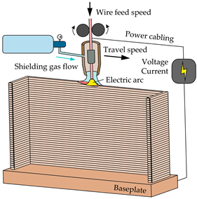
The experimental work was carried out in AISI 316L stainless steel deposited by WAAM using an ESAB Luc Aristo 400 gas metal arc welding power source (Göteborg, Sweden) coupled with a custom 3-axis CNC router table. The wire feedstock, with a diameter of 1.0 mm, was supplied through the welding torch and melted with a spray transfer mode onto hot rolled AISI 316L baseplates with a thickness of 15 mm. The chemical composition of the AISI 316L stainless steel wire feedstock is provided in Table 1 (% wt).
U-shaped vertical thin walls were constructed through single-bead deposition layers along a crisscross sequence to balance the heating and cooling cycles. This strategy helps prevent localized distortions and concentrations of overlapped beads, ensuring that grain growth is not entirely vertical.
The shielding gas used during metal deposition was 99.9% high-purity argon, and the main WAAM processing parameters are summarized in Table 2.
These parameters were retrieved from the authors’ previous work that made use of the same wire and baseplate materials for the construction of thin-walled parts under a stable electric arc during metal deposition [18].

2.2. Mechanical and Thermal Processing

The as-built U-shaped vertical walls were milled before MTP to remove their ribs and ensure uniform thickness and good surface quality of their web plates. These plates were organized into two groups. The first group comprised those subjected to mechanical processing by pre-straining through flat rolling at ambient temperature to achieve 5%, 10%, and 20% thickness reduction T R :
T R = t o t r t 0 × 100 %
where t o and t r   denote the initial and final thicknesses of the web plates, respectively.
The second group consisted of those web plates that were not subjected to mechanical processing ( T R = 0 % ) and retained the mechanical and metallurgical characteristics of the as-built U-shaped vertical walls. These plates served as reference samples and are hereafter referred to as ‘the as-built plates’.
Thermal processing involved annealing some web plates at 1100 °C with a heating rate of 10 °C/min and three different dwell times of 2 h, 4 h, and 6 h. This was performed in an electric furnace, Termolab TH, equipped with a Eurotherm 3216 temperature controller (Worthing, UK) and connected to a Busch Zebra RH 0003 B vacuum pump (Virginia Beach, VA, USA) to maintain a constant pressure of −1 bar and prevent oxidation of the deposited materials. After annealing, the plates were immediately water quenched.
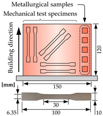
After subjecting the web plates to different MTP conditions, they were cut out into different metallurgical samples and mechanical test specimens by water jetting. These samples and specimens were then used to analyze the influence of MTP on material hardness and strength, formability, and microstructure. Table 3 summarizes the different MTP conditions and provides information on the various metallurgical samples and mechanical test specimens used in the experiments. At least three experiments were performed for each MTP condition.

2.3. Tensile Testing

The metal forming stage of the novel WAAM-based hybrid manufacturing route, which includes MTP, was simulated through tensile tests covering one of the three fundamental modes of deformation commonly found in metal forming. The tests made use of mechanical specimens cut out from the web plates subjected to various MTP conditions along different orientations relative to the building direction (refer to Table 3) and were performed at ambient temperature using an Instron 5900 universal testing machine (Norwood, MA, USA), following the ASTM standard E8/E8M [19]. At least three tests were conducted for each orientation.
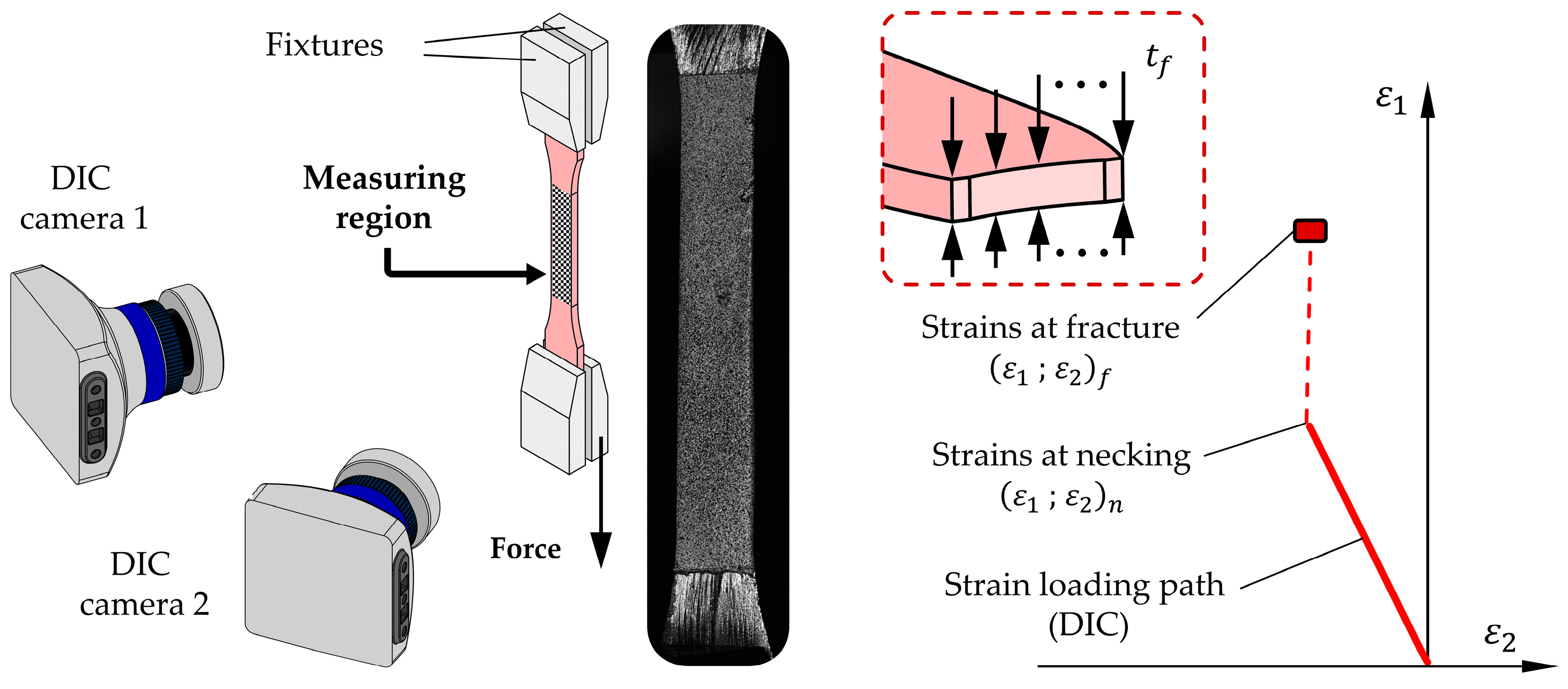
In addition to obtaining the stress vs. strain response for specimens subjected to various MTP conditions, the tensile tests were also used to evaluate differences in formability by determining the corresponding fracture strains through combination of digital image correlation (DIC) with measurements of thickness at fracture.
Figure 2 presents the experimental setup utilized by the DIC system to determine the evolution of the in-plane strains with time ε 1 t , ε 2 t and to plot their combined evolution ε 1 = f ε 2 in the principal strain space after removing the time dependency. The specimens were painted white and subsequently sprayed with a stochastic black dot pattern and the DIC system used was the Dantec Dynamics Q-400 3D equipped with two cameras of 6-megapixel resolution and an acquisition frequency of 10 Hz. The post-processing of results made use of the INSTRA 4D v4.4.4 software (Dantec Dynamics, Skovlunde, Denmark) via a correlation algorithm with a facet size and grid spacing of 13 pixels and 7 pixels, respectively.
The strains at fracture ( ε 1 f , ε 2 f ) were determined from the variation in thickness up to cracking, assuming plane strain loading conditions of d ε 2 0 [20] after necking or after the last measurement of the DIC system (in the case of having measurements beyond necking),
ε 2 f = ε 2 n
ε 1 f = ε 2 f ε 3 f = ε 2 f ln t f t 0
In the above equations, the subscripts n and f represent values at necking and fracture, respectively, while t denotes the thickness of the tensile test specimen. The latter was measured with a stereomicroscope Mitutoyo TM-505B.

2.4. Hardness Testing, Microstruture Observations, and Fractography Analysis

Metallurgical samples cut out from the web plates subjected to various MTP conditions (refer to Table 3) were utilized to determine microhardness and observe the microstructures. Microhardness Vickers measurements were performed in a Mitutoyo HM-112 microhardness tester with an indentation load of 4.905 N (HV0.5) and a loading time of 10 s. The measurements were carried out in accordance with the ASTM E384-17 standard [21], using a constant distance of 2 mm between indentations.
Microstructure observations of the samples subjected to different MTP conditions were carried out in an optical microscope Olympus CK40M (Tokyo, Japan). For this purpose, the metallographic samples were cleaned and polished using a Struers LabPol-30 system (Hovedstaden, Denmark) with emery paper ranging in grit sizes from 600 to 2000 and diamond polishing pastes with roughness varying from 6 μm to 1 μm. After polishing, the samples were chemically etched with aqua regia to reveal the microstructure.
After the tensile tests were completed, the fractured regions were observed using a scanning electron microscope Hitachi S-2400 (Tokyo, Japan) and their morphology was correlated with the strain loading paths obtained from DIC.

3. Results and Discussion

3.1. Thermal Processing

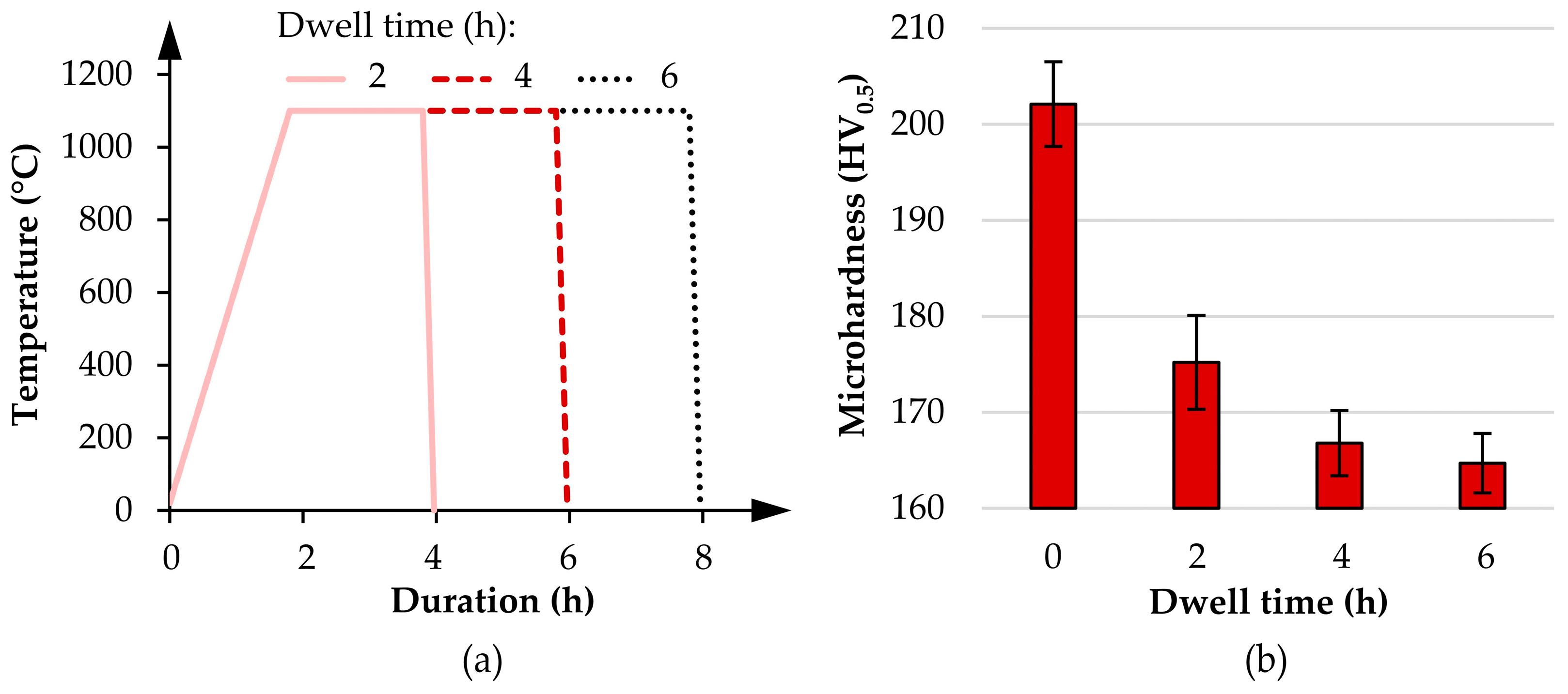
The investigation started by examining the impact of the annealing operation on metallurgical test samples extracted from the as-built plates not subjected to pre-straining (refer to TR = 0% in Table 3). The objective was to analyze the influence of different annealing dwell times on microstructure and identify the thermal processing conditions that give rise to the lowest material hardness due to their importance in hybrid WAAM-based manufacturing routes incorporating metal forming stages.
The results in Figure 3 indicate that an increase in dwell time led to reductions in microhardness, decreasing from 202 HV0.5 for the metallurgical samples not subjected to annealing to approximately 165 HV0.5 for those subjected to annealing with a dwell time of 6 h. This decrease in microhardness suggests changes in the microstructure, a phenomenon that will be discussed in the second part of this section.
However, the decrease in microhardness did not progress linearly, suggesting a saturation dwell time beyond which the decrease became negligible. This is evident in the annealed samples with a dwell time of 6 h which exhibit only a 1.2% difference in microhardness compared to samples annealed with a dwell time of 4 h. This observation justifies the influence of mechanical processing in the next section of the paper which will be solely based on tensile test specimens subjected to annealing with a dwell time of 4 h.
The effectiveness of annealing and its various dwell times is further supported by the microstructure observations presented in Figure 4. Figure 4a depicts the microstructure of the as-built plates, characterized by columnar grains formed through dendritic growth, with primary arms aligned with the building direction. This alignment is consistent with the temperature gradient of the heating and cooling cycles during melting and solidification of the deposited layers [22]. Remelted regions corresponding to the layer boundaries exhibited shorter spaces between the primary arms of dendritic growth, contributing to an irregular microstructure typical of metals with highly anisotropic behavior.
A markedly different microstructure, characterized by a more pronounced γ-austenitic matrix (lighter colors) due to solubilization of δ-ferrite phases (darker colors), was observed upon annealing with a dwell time of 2 h (Figure 4b). Extending the dwell time to 4 h resulted in an even smoother microstructure predominantly composed of an austenitic phase and allowed the columnar grain boundaries to be distinguished (Figure 4c). Small agglomerations of large-size equiaxed grains were also present in the samples due to reductions in total grain boundary energy, leading to significant decreases in material strength, as it will be demonstrated in the next section of the paper. This result supports the previous conclusion that the dwell time during annealing should not exceed the 4 h limit.

3.2. Mechanical and Thermal Processing

Figure 5 shows the microstructure of the metallurgical samples subjected to different values of pre-straining by flat rolling (mechanical processing) and subsequent annealing (thermal processing) at 1100 °C with a dwell time of 4 h (i.e., different MTP conditions). The microstructure of the as-built plates, not subject to MTP and depicted in Figure 4a, should be considered for reference and comparison purposes.
The microstructure observed for the samples subjected to pre-straining with T R = 5 % and annealing with a dwell time of 4 h (Figure 5a) shows little difference compared to that of Figure 4c, suggesting that low levels of pre-straining (i.e., low levels of mechanical processing) are insufficient to promote the growth of recrystallized grains during annealing. In essence, the microstructure of the samples subjected to MTP with T R = 5 % closely resembled that of the as-built plates solely subjected to annealing.
Changes in microstructure became apparent for the samples subjected to MTP with T R = 10 % which displayed regions of polygonal grain features of irregular but relatively small size (Figure 5b). Still, the resulting grain structure was not fully equiaxed, because the level of pre-straining was only sufficient to promote partial recrystallization [23].
With a further increase in pre-straining to T R = 20 % , the original microstructure was completely replaced by a fully equiaxed microstructure comprising regular, small-sized, polygonal grains (Figure 5c). The conclusion to be drawn is that, without significant pre-straining, the grain size in the as-built plates remains largely unchanged after annealing. However, when the level of pre-straining in MTP is increased to T R = 20 % , the stored energy of the deformed grains resulting from increased dislocation density stimulates recrystallization annealing. This leads to a transition from a highly irregular dendritic-based columnar grain microstructure to a fine equiaxed grain microstructure without phase change (Figure 5c).

3.3. Flow Curves

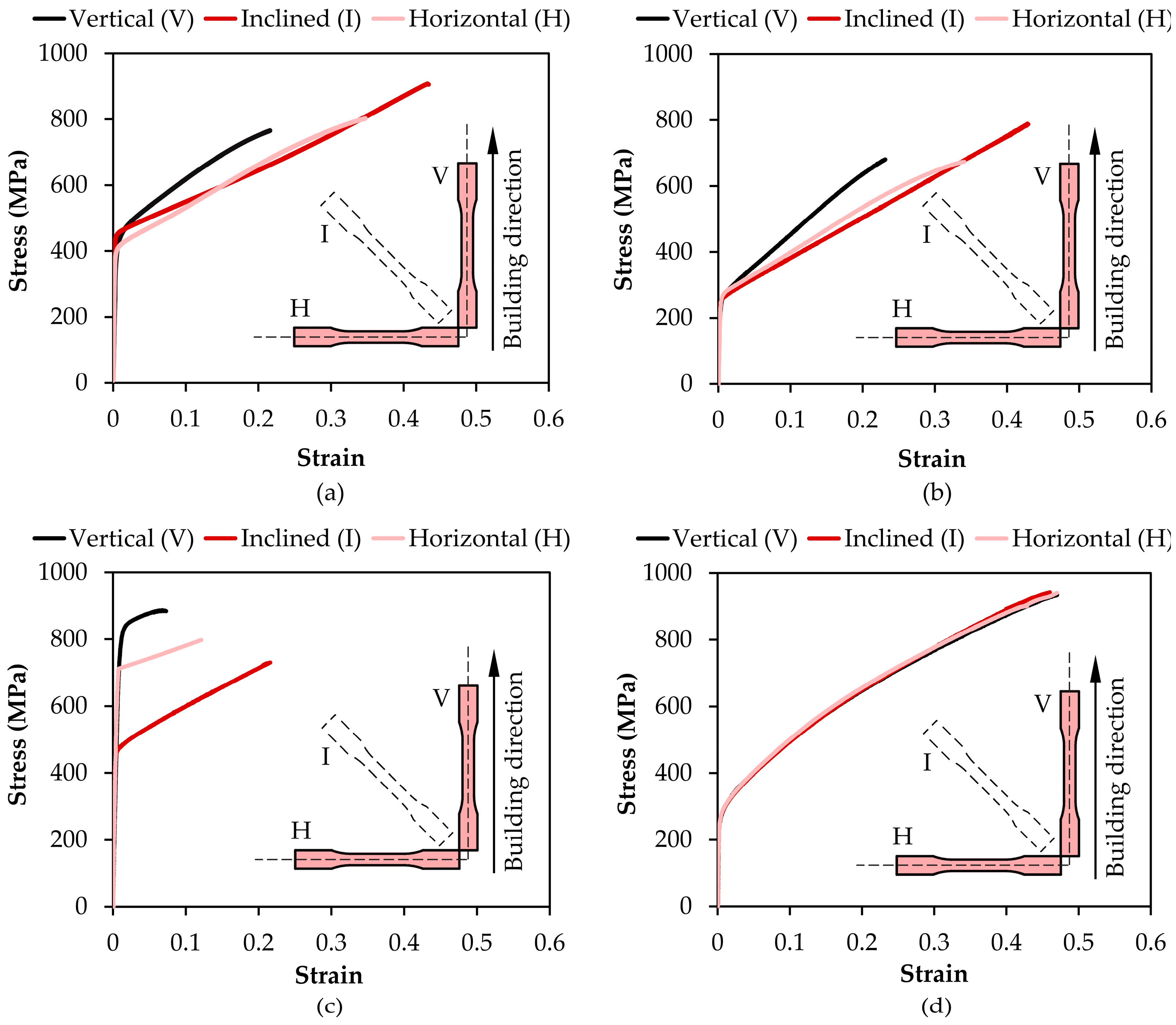
Figure 6a–d present the material flow curves (true stress vs. true strain curves) of the as-built plates and those plates subjected to partial or complete MTP conditions. The test specimens were extracted from three different orientations relative to the building direction, as shown in Table 3.
As seen in Figure 6a, the flow curves of the as-built plates obtained from test specimens and aligned with the vertically built direction revealed higher strength than that recorded in relation to other directions. This is attributed to the dendritic-based columnar grain microstructure of the as-built material [24] which gives an anisotropic stress response dependent on the build direction.
In the case of test specimens subjected to partial MTP consisting only of intermediate annealing at 1100 °C with a dwell time of 4 h, the material became softer (Figure 6b) than the as-built material due to significant solubilization of δ-ferrite phases (refer to Figure 4). However, the evolution trend of the flow curves in each direction was similar to that of the as-built plates with substantial anisotropy because thermal processing without pre-straining cannot promote recrystallization annealing. In other words, despite some material softening, there were no significant changes in the microstructure, which essentially remained columnar.
In contrast, the test specimens subjected to partial MTP consisting only of pre-straining with T R = 20 % , without subsequent annealing, experienced a marked increase in strength and anisotropy, accompanied by a noteworthy reduction in elongation (Figure 6c). This is attributed to increased dislocation density due to work hardening, limiting the applicability of metal forming in hybrid WAAM-based manufacturing routes.
However, when the test specimens were subject to complete MTP conditions consisting of pre-straining with T R = 20 % and annealing at 1100 °C with a dwell time of 4 h, the material became softer than that of the as-build plates, elongation increased up to the maximum true strain value of 0.5, and anisotropy was eliminated (Figure 6d). All of this confirms the replacement of the original microstructure by a fully equiaxed microstructure comprising regular, small-sized, polygonal grains (refer to Figure 5c). This transformation is attributed to the accumulation of energy in the form of lattice distortion inside the pre-strained test specimens, which facilitates the initiation of recrystallization annealing.

3.4. Formability

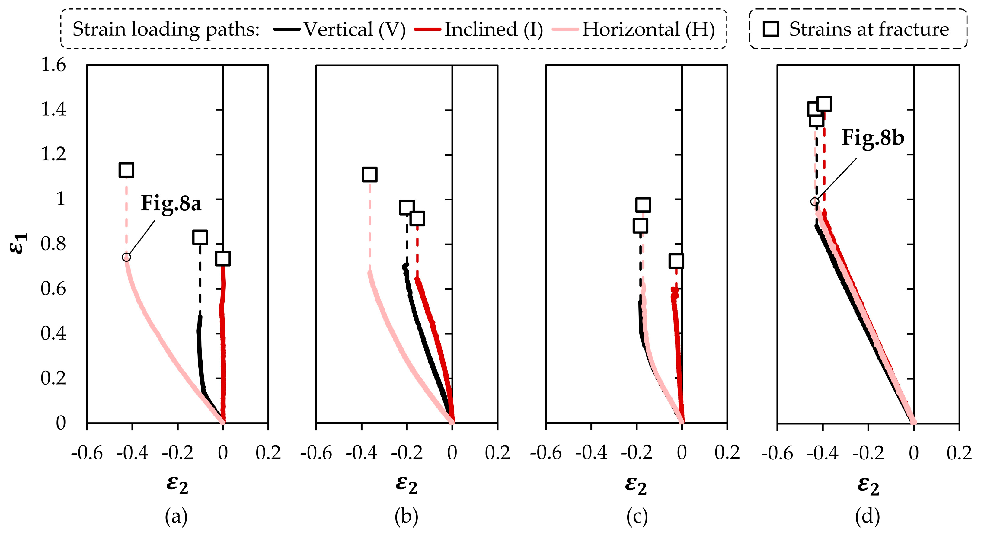
Figure 7a–d present the strain loading paths and fracture strains in the principal strain space ε 1 = f ε 2 obtained from the tensile tests performed on specimens cut out from the as-built plates and from web plates subjected to partial or complete MTP. The specimens were taken from three different orientations in close agreement with the methodology used to determine the material flow curves in Section 3.3.
As seen in Figure 7a, the strain loading paths retrieved from the tensile test specimens cut out from the as-built plates confirmed a high level of anisotropy with three distinctly different evolutions, which range from near pure shear ( d ε 2 / d ε 1 1 ) to plane strain deformation ( d ε 2 / d ε 1 = 0 ) [25]. These results corroborate previous microstructure observations and flow curves, highlighting the critical role played by the building direction on the stress vs. strain response of the deposited material.
Tensile test specimens subjected to partial MTP conditions exhibited different strain loading paths with signs of strong anisotropy. In the case of specimens subjected only to intermediate annealing at 1100 °C with a dwell time of 4 h (Figure 7b), there was a trend among the different strain loading paths towards pure tension ( d ε 1 / d ε 2 = 2 ) combined with a slight increase in the fracture strain values and associated formability limits. In the case of specimens subjected only to pre-straining with T R = 20 % (Figure 7c), there was a reduction in the fracture strain values, confirming a reduction in fracture toughness. All these results are attributed to the microstructure of the test specimens with partial MTP conditions which is characterized by a columnar grain structure.
The strain loading paths obtained from the test specimens subjected to complete MTP conditions, consisting of pre-straining with T R = 20 % and annealing at 1100 °C with a dwell time of 4 h (Figure 7d), were remarkably different from all the others. They showed no sign of anisotropy, with all the specimens providing linear slopes with d ε 1 / d ε 2 2 up to the onset of diffuse necking. The fracture strain values were found to be the highest across the entire set of testing conditions, with an increase of approximately 30% compared to the test specimens extracted from the as-built plates.
Moreover, a comparison between the images obtained from DIC immediately before the failure for the test specimens cut out from the horizontal direction of the as-built plates (Figure 8a) and those subjected to MTP—involving pre-straining with TR = 20% and annealing at 1100 °C for 4 h (Figure 8b)—clearly shows the absence of striations along the gauge length of the latter specimens. Striations are attributed to the development of stable necks at multiple locations within the primary arms of the dendrites, and their elimination in Figure 7d confirms the occurrence of recrystallization annealing during which the highly irregular dendritic-based columnar grain structure transforms into a fine equiaxed grain microstructure.
All these findings underscore the importance of MTP in enhancing the formability of the material deposited by WAAM for subsequent metal forming stages, as required by hybrid manufacturing routes.
Figure 9a–d show images obtained from scanning electron microscopy (SEM) of the fractured surfaces of selected tensile test specimens. At first glance, the morphology of the cracks consisted of circular dimple-based structures oriented perpendicular to the plane of the image. This is typically observed in images such as Figure 9a, obtained from the fractured surface of tensile test specimens cut out from the as-built plates, and suggests occurrence of crack opening by tension (mode I of fracture mechanics). However, upon closer examination of the image in Figure 9a, it became evident that the morphology of the fractured surface was highly stochastic in terms of dimple size. This is attributed to the nucleation of microvoids at grain boundaries and to the subsequent coalescence of microvoids, increasing the dimple sizes.
In the case of tensile test samples subjected to partial MTP consisting only of intermediate annealing at 1100 °C with a dwell time of 4 h (Figure 9b) or only pre-straining with T R = 20 % (Figure 9c), the overall dimple size was smaller. However, the morphology of the fractured surface was composed of shallow dimples and smoother regions free of dimples. This suggests the occurrence of mixed-mode types of crack opening, likely associated with some degree of through-thickness shearing arising from the strong anisotropic behavior of the material and the development of striations along the gauge length of specimens exhibiting a dendritic-based columnar grain structure.
Finally, the fractured surface of the tensile test samples subjected to complete MTP conditions (Figure 9d) showed a regular circular dimple-based structure typical of a material with high ductility. This image further underscores the importance of MTP in enhancing material formability to withstand the large plastic deformations arising from the hybridization of WAAM with metal forming.

4. Conclusions

The applicability domain of the hybridization of wire arc additive manufacturing (WAAM) with metal forming can be significantly expanded by including an intermediate MTP stage aimed at softening and enhancing the formability of the deposited material.
Results obtained with AISI 316L stainless steel suggest that mechanical processing up to strain levels analogous to T R = 20 % in rolling, combined with thermal processing through annealing at 1100 °C with a dwell time of 4 h, allows for gains in material formability of over 30%. The effectiveness of MTP is attributed to recrystallization annealing that replaces the original microstructure with a fully equiaxed microstructure comprising regular, small-sized, polygonal grains without phase change.
The use of partial MTP consisting of a conventional intermediate annealing stage can provide some material softening, but the gains in formability are limited, and anisotropy is not eliminated because there are no significant changes in the microstructure, which essentially remains columnar.
Complete MTP with small levels of mechanical processing (e.g., pre-straining with T R = 5 % or T R = 10 % ) does not give rise to changes in microstructure because the accumulation of energy resulting from plastic deformation in the form of lattice distortion is not significant enough to facilitate the initiation of recrystallization during annealing.

Author Contributions

Conceptualization, J.P.M.P. and C.M.A.S.; methodology, J.P.M.P. and C.M.A.S.; software, B.B.; validation, J.P.M.P., B.B. and I.M.F.B.; formal analysis, J.P.M.P. and B.B.; investigation, J.P.M.P., B.B., I.M.F.B., C.M.A.S. and P.A.F.M.; resources, J.P.M.P., I.M.F.B. and C.M.A.S.; data curation, J.P.M.P. and B.B.; writing—original draft preparation, J.P.M.P. and P.A.F.M.; writing—review and editing, I.M.F.B. and C.M.A.S.; visualization, B.B.; supervision, C.M.A.S. and P.A.F.M.; project administration, P.A.F.M.; funding acquisition, P.A.F.M. All authors have read and agreed to the published version of the manuscript.

Funding

This research was funded by Fundação para a Ciência e a Tecnologia of Portugal and IDMEC under LAETA-UIDB/50022/2020 and PTDC/EME-EME/0949/2020.

Data Availability Statement

The raw data supporting the conclusions of this article will be made available by the authors on request.

Acknowledgments

The authors would like to acknowledge the financial support provided by Fundação para a Ciência e a Tecnologia of Portugal (FCT) and IDMEC via the project LAETA Base Funding (DOI: 10.54499/UIDB/50022/2020).

Conflicts of Interest

The authors declare no conflict of interest.

References

  1. ISO/ASTM 52900-21; Additive Manufacturing—General Principles—Fundamentals and Vocabulary. ASTM International: West Conshohocken, PA, USA, 2021.
  2. Cunningham, C.R.; Wang, J.; Dhokia, V.; Shrokani, A.; Newman, S.T. Characterisation of Austenitic 316 LSi Stainless Steel Produced by Wire Arc Additive Manufacturing with Interlayer Cooling. In Proceedings of the 2019 Annual International Solid Freeform Fabrication Symposium—An Additive Manufacturing Conference; Austin, Austin, TX, USA, 12–14 August 2019. [Google Scholar] [CrossRef]
  3. Bi, X.; Li, R.; Hu, Z.; Gu, J.; Jiao, C. Microstructure and Texture of 2205 Duplex Stainless Steel Additive Parts Fabricated by the Cold Metal Transfer (CMT) Wire and Arc Additive Manufacturing (WAAM). Metals 2022, 12, 1655. [Google Scholar] [CrossRef]
  4. Sampaio, R.F.V.; Pragana, J.P.M.; Bragança, I.M.F.; Silva, C.M.A.; Nielsen, C.V.; Martins, P.A.F. Modelling of Wire-Arc Additive Manufacturing—A Review. Adv. Ind. Manuf. Eng. 2023, 6, 100121. [Google Scholar] [CrossRef]
  5. Shah, A.; Aliyev, R.; Zeidler, H.; Krinke, S. A Review of the Recent Developments and Challenges in Wire Arc Additive Manufacturing (WAAM) Process. J. Manuf. Mater. Process. 2023, 7, 97. [Google Scholar] [CrossRef]
  6. Hönnige, J.R.; Colegrove, P.A.; Ahmad, B.; Fitzpatrick, M.E.; Ganguly, S.; Lee, T.L.; Williams, S.W. Residual Stress and Texture Control in Ti-6Al-4V Wire + Arc Additively Manufactured Intersections by Stress Relief and Rolling. Mater. Des. 2018, 150, 193–205. [Google Scholar] [CrossRef]
  7. Korkmaz, M.E.; Waqar, S.; Garcia-Collado, A.; Gupta, M.K.; Krolczyk, G.M. A Technical Overview of Metallic Parts in Hybrid Additive Manufacturing Industry. J. Mater. Res. Technol. 2022, 18, 384–395. [Google Scholar] [CrossRef]
  8. Pragana, J.P.M.; Sampaio, R.F.V.; Bragança, I.M.F.; Silva, C.M.A.; Martins, P.A.F. Hybrid Metal Additive Manufacturing: A State–of–the-Art Review. Adv. Ind. Manuf. Eng. 2021, 2, 100032. [Google Scholar] [CrossRef]
  9. Ambrogio, G.; Gagliardi, F.; Muzzupappa, M.; Filice, L. Additive-incremental forming hybrid manufacturing technique to improve customised part performance. J. Manuf. Process. 2019, 37, 386–391. [Google Scholar] [CrossRef]
  10. Meiners, F.; Ihne, J.; Jürgens, P.; Hemes, S.; Mathes, M.; Sizova, I.; Bambach, M.; Hama-Saleh, R.; Weisheit, A. New Hybrid Manufacturing Routes Combining Forging and Additive Manufacturing to Efficiently Produce High Performance Components from Ti-6Al-4V. Procedia Manuf. 2020, 47, 261–267. [Google Scholar] [CrossRef]
  11. Merklein, M.; Schulte, R.; Papke, T. An Innovative Process Combination of Additive Manufacturing and Sheet Bulk Metal Forming for Manufacturing a Functional Hybrid Part. J. Mater. Process. Technol. 2021, 291, 117032. [Google Scholar] [CrossRef]
  12. López, C.; Elías-Zúñiga, A.; Jiménez, I.; Martínez-Romero, O.; Siller, H.R.; Diabb, J.M. Experimental Determination of Residual Stresses Generated by Single Point Incremental Forming of AlSi10Mg Sheets Produced Using SLM Additive Manufacturing Process. Materials 2018, 11, 2542. [Google Scholar] [CrossRef]
  13. Bambach, M.; Sviridov, A.; Weisheit, A.; Schleifenbaum, J. Case Studies on Local Reinforcement of Sheet Metal Components by Laser Additive Manufacturing. Metals 2017, 7, 113. [Google Scholar] [CrossRef]
  14. Wu, B.; Pan, Z.; Ding, D.; Cuiuri, D.; Li, H.; Xu, J.; Norrish, J. A Review of the Wire Arc Additive Manufacturing of Metals: Properties, Defects and Quality Improvement. J. Manuf. Process. 2018, 35, 127–139. [Google Scholar] [CrossRef]
  15. Gornyakov, V.; Sun, Y.; Ding, J.; Williams, S. Modelling and Optimising Hybrid Process of Wire Arc Additive Manufacturing and High-Pressure Rolling. Mater. Des. 2022, 223, 111121. [Google Scholar] [CrossRef]
  16. Gu, J.; Ding, J.; Williams, S.W.; Gu, H.; Bai, J.; Zhai, Y.; Ma, P. The Strengthening Effect of Inter-Layer Cold Working and Post-Deposition Heat Treatment on the Additively Manufactured Al–6.3Cu Alloy. Mater. Sci. Eng. A 2016, 651, 18–26. [Google Scholar] [CrossRef]
  17. Silva, C.M.A.; Pragana, J.P.M.; Bragança, I.M.F.; Martins, P.A.F. Mechanical and thermal processing of wire-arc additively deposited stainless steel. CIRP Ann. 2024, in press. [Google Scholar] [CrossRef]
  18. Pragana, J.P.; Bragança, I.M.; Reis, L.; Silva, C.M.; Martins, P.A. Formability of Wire-Arc Deposited AISI 316L Sheets for Hybrid Additive Manufacturing Applications. Proc. Inst. Mech. Eng. Part L J. Mater. Des. Appl. 2021, 235, 2839–2850. [Google Scholar] [CrossRef]
  19. ASTM E8/E8M-22; Standard Test Methods for Tension Testing of Metallic Materials. ASTM International: West Conshohocken, PA, USA, 2024.
  20. Atkins, A.G. Fracture in Forming. J. Mater. Process. Technol. 1996, 56, 609–618. [Google Scholar] [CrossRef]
  21. ASTM E384-17; Standard Test Method for Microindentation Hardness of Materials. ASTM International: West Conshohocken, PA, USA, 2022.
  22. Lee, S.H. CMT-Based Wire Arc Additive Manufacturing Using 316L Stainless Steel: Effect of Heat Accumulation on the Multi-Layer Deposits. Metals 2020, 10, 278. [Google Scholar] [CrossRef]
  23. Elmer, J.W.; Fisher, K.; Gibbs, G.; Sengthay, J.; Urabe, D. Post-Build Thermomechanical Processing of Wire Arc Additively Manufactured Stainless Steel for Improved Mechanical Properties and Reduction of Crystallographic Texture. Addit. Manuf. 2022, 50, 102573. [Google Scholar] [CrossRef]
  24. Jin, W.; Zhang, C.; Jin, S.; Tian, Y.; Wellmann, D.; Liu, W. Wire Arc Additive Manufacturing of Stainless Steels: A Review. Appl. Sci. 2020, 10, 1563. [Google Scholar] [CrossRef]
  25. Paul, S.K.; Manikandan, G.; Verma, R.K. Prediction of Entire Forming Limit Diagram from Simple Tensile Material Properties. J. Strain Anal. Eng. Des. 2013, 48, 386–394. [Google Scholar] [CrossRef]
Figure 1. Schematic representation of the novel WAAM-based hybrid additive manufacturing route comprising: (a) metal deposition by WAAM, (b) mechanical and thermal processing (MTP), and (c) metal forming.
Metals 14 00716 g001
Figure 2. Schematic representation of the methods and procedures used to obtain the strain loading paths and the fracture strains in principal strain space ε 1 = f ε 2 .
Metals 14 00716 g002
Figure 3. (a) Thermal cycles of annealing with different dwell times and corresponding (b) microhardness values (HV0.5). The microhardness values of metallurgical samples not subjected to annealing are plotted for a dwell time of 0 h.
Metals 14 00716 g003
Figure 4. Microstructure observations of metallurgical samples extracted from the as-built plates ( T R = 0 % ) (a) not subjected to annealing and (b) subjected to annealing with dwell times of 2 h and (c) 4 h. The pictures at the bottom are magnified versions of those at the top.
Metals 14 00716 g004
Figure 5. Microstructure observations of metallurgical samples subjected to MTP with pre-straining levels of (a) 5 % , (b) 10%, and (c) 20%, followed by annealing at 1100 °C with a dwell time of 4 h.
Metals 14 00716 g005
Figure 6. Flow curves of the deposited AISI 316L stainless steel in the: (a) as-built condition, (b) after annealing at 1100 °C with a dwell time of 4 h, (c) after pre-straining with T R = 20 % , and (d) after MTP consisting of pre-straining with T R = 20 % and annealing at 1100 °C with a dwell time of 4 h.
Metals 14 00716 g006
Figure 7. Strain loading paths and fracture strains in the principal strain space for tensile test specimens cut out from the deposited AISI 316L stainless steel web plates in the: (a) as-built condition, (b) after annealing at 1100 °C with a dwell time of 4 h, (c) after pre-straining with T R = 20 % , and (d) after MTP consisting of pre-straining with T R = 20 % and annealing at 1100 °C with a dwell time of 4 h.
Metals 14 00716 g007
Figure 8. Distributions of experimental major and minor strains obtained from DIC before failure for the tensile test specimens identified in (a) Figure 7a and (b) Figure 7d.
Metals 14 00716 g008
Figure 9. Scanning electron microscopy (SEM) of the fracture surface of tensile test specimens cut out from the deposited AISI 316L stainless steel web plates in the: (a) as-built condition, (b) after annealing at 1100 °C with a dwell time of 4 h, (c) after pre-straining with T R = 20 % , and (d) after MTP consisting of pre-straining with T R = 20 % and annealing at 1100 °C with a dwell time of 4 h.
Metals 14 00716 g009
Table 1. Chemical composition of the AISI 316L stainless steel (% wt).
ElementFeCrNiMoMnSiNC
% wtBal.18.212.02.61.70.40.040.01
Table 2. WAAM processing parameters with schematic representation.
Processing ParametersSchematic Representation
Voltage:Current:Metals 14 00716 i001
16.5 V100 A
Wire feed speed:
6 m/min
Travel speed:
600 mm/min
Shielding gas flow rate:
10 L/min
Stick-out length:
10 mm
Table 3. MTP conditions with a schematic representation of the metallurgical samples and mechanical test specimens.
Processing ConditionsSamples and Test Specimens
As-builtMechanicalThermalMetals 14 00716 i003
T R = 0 %
Dwell time = 0 h
T R = 5 % ; 10 % ; 20   % Dwell time = 2 h; 4 h; 6 h
(annealing at 1100 °C)
Metals 14 00716 i002
Disclaimer/Publisher’s Note: The statements, opinions and data contained in all publications are solely those of the individual author(s) and contributor(s) and not of MDPI and/or the editor(s). MDPI and/or the editor(s) disclaim responsibility for any injury to people or property resulting from any ideas, methods, instructions or products referred to in the content.