Article

Preparation and Characterization of Duplex PEO/UV-Curable Powder Coating on AZ91 Magnesium Alloys

by
Łukasz Florczak
1,*,
Katarzyna Pojnar
2,
Barbara Kościelniak
3 and
Barbara Pilch-Pitera
4
1
Department of Physical Chemistry, Faculty of Chemistry, Rzeszow University of Technology, 35-959 Rzeszow, Poland
2
Doctoral School of Engineering and Technical Sciences, Rzeszow University of Technology, 35-959 Rzeszow, Poland
3
Department of Materials Science, Faculty of Mechanical Engineering and Aeronautics, Rzeszow University of Technology, 35-959 Rzeszow, Poland
4
Department of Polymers and Biopolymers, Faculty of Chemistry, Rzeszow University of Technology, 35-959 Rzeszow, Poland
*
Author to whom correspondence should be addressed.
Metals 2024, 14(6), 733; https://doi.org/10.3390/met14060733
Submission received: 30 May 2024 / Revised: 15 June 2024 / Accepted: 17 June 2024 / Published: 20 June 2024

Abstract

:
Magnesium alloys, because of their excellent strength-to-weight ratio, are increasingly used in many industries. When used in external elements, the key factor is to provide adequate anticorrosion protection. High-temperature, cured-powder coatings are widely used to protect most metals, but their use on magnesium alloys is difficult as a result of the instability of the magnesium substrate at elevated temperatures. Another problem is ensuring the proper adhesion of the organic coating to the magnesium substrate. This paper presents the procedure for the synthesis of a duplex coating on AZ91 magnesium alloy. The topcoat was a powder coating based on acrylic resin, the main ingredient of which was glycidyl methacrylate. Because of the presence of epoxy groups, the coating was cured using ultraviolet (UV) radiation (low-temperature technology). The conversion subcoating was produced by plasma electrolytic oxidation (PEO) in an alkaline silicate electrolyte. The synthesized coating system was tested, among others, for microscopic (SEM), adhesive (mesh of cuts), and anticorrosion (EIS). The duplex PEO/UV-curable powder coating showed very good adhesion to the metal and increased the anticorrosion properties of the magnesium substrate, compared to the powder coating produced directly on the magnesium alloy and on an alternative conversion coating (synthesized in the process of chemical zircon phosphating).

Graphical Abstract

1. Introduction

Interest in magnesium alloys increases every year [1]. This material was used, among others, in the automotive, aerospace, and biomedical industries [2,3,4]. Popular magnesium alloys of the AZ and AM series (containing mainly aluminum as alloying elements and zinc or manganese, respectively) are characterized by a high strength-to-weight ratio, excellent electromagnetic shielding, high damping properties, and good dimensional stability at ambient temperature. Calcium and strontium are introduced to improve the biocompatibility of magnesium [5]. On the other hand, the addition of rare earth elements (Gd, Nd, and Y) improves the mechanical properties at elevated temperatures. However, these alloys (e.g., WE43, EV31) are expensive, and their use is limited to the specialized aerospace industry. The main disadvantage of magnesium is its high reactivity (susceptibility to corrosion) in aqueous solutions and humid air, especially in the presence of chloride ions [6,7,8,9]. A partial improvement of the anticorrosion properties is achieved by introducing alloy additives. In addition, surface protection can also be used in the form of various types of coatings [10,11,12]. These include conversion coatings (chemical and electrochemical), organic (polymer) coatings, gas-phase deposition layers (chemical and physical), and laser surface processes.
Plasma electrolytic oxidation (PEO), also called micro arc oxidation (MAO), is a high-voltage anodizing process that allows the synthesis of electrochemical conversion coatings, including magnesium alloys, composed mainly of the oxide of the substrate material and components derived from the electrolyte [13,14,15,16,17,18]. The observed development of the PEO technique is related to, among others, introduced restrictions on the use of classic conversion coatings based on harmful chromate electrolytes (e.g., Registration Evaluation Authorisation and Restriction of Chemicals; REACH) [19,20]. A characteristic feature of this process is the occurrence of electric discharges above the “breakdown potential” and the incorporation of electrolyte components into the structure of the newly formed conversion layer, which occurs mainly after exceeding the “critical potential”. Most often, the PEO process is carried out under galvanostatic conditions using a pulsed current (mono or bipolar) in alkaline baths based on silicates or phosphates with the addition of fluoride ions [21,22,23,24,25]. The converted coating produced exhibits improved hardness, excellent adhesion to the magnesium substrate, and increased anticorrosion properties. However, the PEO ceramic coating is sensitive to the pitting corrosion that occurs in the presence of chloride ions.
Organic coatings are typical top layers that provide an excellent protective barrier against aggressive environmental conditions [26]. These coatings can be applied (i.e., formed) by painting, powder coating, E-coating, or sol–gel coating. Currently, as a result of pro-ecological activities, there is a tendency to replace organic solvent coatings with high-solid, waterborne, or powder products. Powder coatings consist of 100% solid substances, so they meet the directives of the European Parliament on the reduction of volatile organic compound emissions (VOCs) [27]. In addition, powder coatings meet the criteria of the so-called “5E” (efficiency, economy, energy savings, environmental compliance, and excellence of finish). Depending on the selection of components for the powder coating composition, we can design coatings that meet the criteria set by consumers—weather durability, corrosion resistance, high mechanical properties such as hardness, scratch resistance, impact resistance, and adhesion to the surface [28]. Acrylic powder coatings with acrylic-resin-containing epoxy groups are applied to improve the adhesion of the coating to the steel surface and provide anticorrosion protection [29,30]. Standard powder coating systems are cured at high temperatures (180–200 °C) contributing to high energy consumption, which generates high costs. The current trend in the powder coating industry is low temperature, including UV-cured systems (cured at 160 °C and below) [31,32,33,34,35]. This is an important aspect with respect to the reduction in production costs, environmental impact, and the possibility of using powder coatings on highly sensitive materials, such as wood [36] or the magnesium alloy of the AZ series, which lose their mechanical properties at elevated temperatures [37,38,39].
An increasing number of studies are concerned with multilayer coating systems on magnesium alloys in order to achieve a satisfactory corrosion protection effect with the desired mechanical parameters [40]. In such solutions, the sublayer is often a conversion coating created in the PEO process, and the top layer is a polymeric coating, often with biocompatible, superhydrophobic, or self-healing properties [41,42,43,44]. So far, there have been no reports in the literature on the use of UV-curable coatings on magnesium alloys.
In this work, the possibility of using a UV-cured powder coating on AZ91 magnesium alloy was examined. The synthesis method and physicochemical properties of the acrylic resin used were optimized and investigated in our previous work [35]. To ensure proper adhesion of the organic coating to the magnesium substrate, a conversion coating was created on its surface. For this purpose, the plasma electrolytic oxidation process was applied in an alkaline silicate electrolyte using a monopolar pulse signal. The synthesized duplex PEO/UV-curable powder coating on magnesium alloys was evaluated for physical and anticorrosion properties. The obtained results were compared with those of an acrylic powder coating applied directly to the magnesium alloy and to a previously chemically produced conversion coating in a commercially available electrolyte intended for zircon phosphating.

2. Materials and Methods

2.1. Substrate Material

The magnesium alloy AZ91 (according to ASTM B94) [45] of dimensions 5 cm × 5 cm × 1 cm was utilized as the substrate material. The chemical composition of the alloy as identified by the ARL Advant XP Sequential X-ray Fluorescence Spectrometer (Thermo Fisher Scientific Inc., Waltham, MA, USA) is 8.77 wt.% Al, 0.74 wt.% Zn, 0.18 wt.% Mn, and Mg balance. Before any coating treatment, the samples were mechanically ground with water-cooled SiC emery paper up to p1200, then washed in deionized water, ultrasonically degreased with acetone, and dried with an air stream.

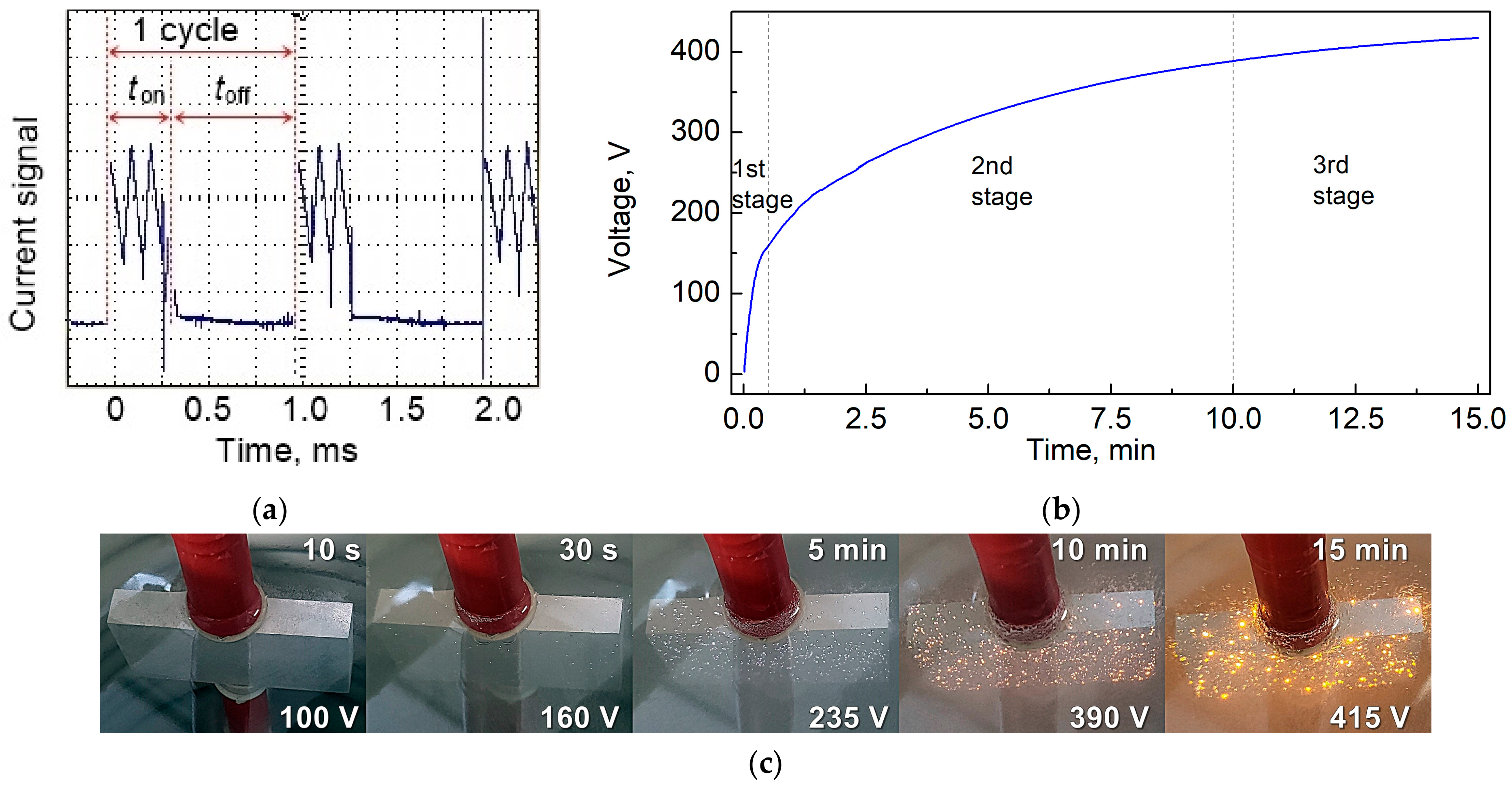
2.2. Synthesis of Conversion Coatings

The conversion coating was produced by high-voltage electrochemical anodization using the plasma electrolytic oxidation (PEO) process. The electrolyte used in the PEO method consisted of 10 g/L Na2SiO3·5H2O, 4 g/L NaOH, and 3 g/L NaF. The PEO process time was set at 15 min and the electrolyte temperature was controlled and kept below 15 °C. The magnesium samples were used as an anode, and stainless steel plate as a cathode. After the PEO procedure, the samples were rinsed in deionized water and dried with an air stream. PEO treatment was carried out with a homemade pulse power supply, using a unipolar current impulse at a current density of 40 mA/cm2, frequency of 1 kHz, and duty cycle of 30%. The power supply used generated a sawtooth signal with a frequency of 9 kHz. The shape of a single current pulse is presented in Figure 1a. Changes in the voltage value and appearance of the magnesium alloy surface during the oxidation process are shown in Figure 1b and Figure 1c, respectively.
The electrical parameters used created a current signal with a lifetime of 0.3 ms, followed by a 0.7 ms break. As the process progressed, the voltage required to maintain the set current value increased. The PEO process can be divided into 3 stages: (1st) conventional oxidation (without electrical discharges), (2nd) sparking anodizing (with small, white, and fast-moving discharges), and (3rd) arc oxidation (with large, orange, long-lasting discharges). In the metal–electrolyte–current conditions system used, the breakdown voltage (starting stage 2) was 160 V, and the critical voltage (starting stage 3) was 390 V. The final voltage was 425 V, and no destructive discharges were observed.
To compare the effectiveness of the conversion layer produced in the PEO process as an intermediate coating between the organic layer and the magnesium substrate, an additional synthesis of the subcoating was carried out by chemical conversion using a 1% vol. Eskaphor Z 2000 C solution (Haug Chemie GmbH, Sinsheim, Germany)—a commercially available bath intended for zircon phosphating (concentrate solution composition: 1–3% H2ZrF6, 0.5–5% H3PO4, and 0.5–1% C6H4NNaO5S [sodium 3-nitrobenzenesulfonate]). This solution is used in a standard pretreatment, preferred before powder coating, suitable for multimetals. The chemical conversion process was carried out by immersing a magnesium sample in a solution at 40 °C for 4 min, according to the manufacturer’s recommendations.

2.3. Synthesis of Powder Composition

To synthesize the acrylic resin, a mixture of monomers glycidyl methacrylate (GMA), methyl methacrylate (MMA), and n-butyl acrylate (BA) was used in a molar ratio of 3:6:1 with the addition of 1.7 wt.% initiator of free radical polymerization—azobisisobutyronitrile (AIBN). The polymerization reaction was initially carried out in a three-neck flask equipped with a reflux condenser with magnetic stirrer, without access to oxygen at a temperature of 80 °C for several minutes (to noticeable increase in viscosity). Then, the nonsolidified resin mixture was poured into a PTFE (polytetrafluoroethylene) mold for solidification which was heated in an oven to 80 °C (until completely solidified).
The prepared mixture was ground on an electric grinder. Then, to the acrylic resin was added 2 wt.% triarylsulfonium hexafluorophosphate (photoinitiator), 1 wt.% benzoin (degassing agent), and 2 wt.% Byk 368P (resinflow) and the whole was extruded in a corotating twin-screw mini extruder EHP 2 × 12 Sline (Zamak Mercator, Skawina, Poland) at an elevated temperature (95–125 °C), used the screw rotational speed equal 100 rpm. After extrusion, the mixture was cooled, pulverized, and sieved in a 100 μm sieve.

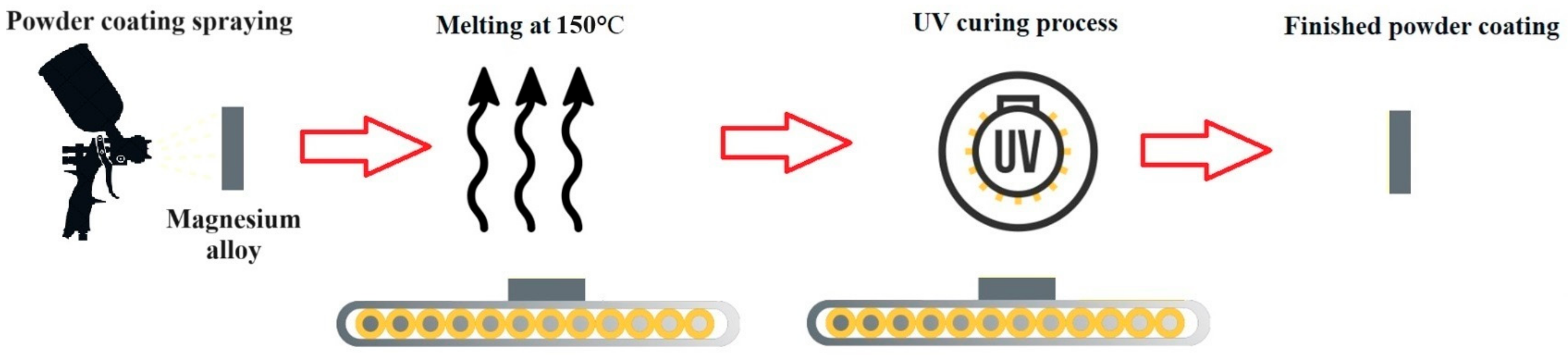
2.4. Preparation of UV-Cured Powder Coating

The powder composition obtained was applied to magnesium alloy samples (without and with conversion layer) using an electrostatic gun PEM X-1 controlled by EPG Sprint X (CORONA) (Wagner, Altstäten, Switzerland). Then, the powder coating was melted at 150 °C for 5 min and immediately cured for 42 s using a UVC-5 Compact Light-Curing Conveyor System equipped (Dymax, Wiesbaden, Germany) with a mercury lamp with a power of 850 W. The stages of powder coating production are schematically illustrated in Figure 2.
Depending on the coating methods used, the samples were named according to the scheme presented in Table 1.

2.5. Coatings Characterization

The optical microscope LAB 40 (Opta-Tech, Warsaw, Poland) was used to initially assess the surface morphology of the coatings produced on magnesium alloy. The microstructures, morphologies, and compositions of the obtained coatings were analyzed by scanning electron microscopy (SEM) with a coupled energy-dispersive X-ray spectroscopy (EDS) detector using Phenom XL (Thermo Fisher Scientific Inc., Waltham, MA, USA).
The thicknesses of the coatings were measured by the eddy current method (nonmagnetic coating on ferromagnetic metal substrate mode) using a micro-Tri-gloss measurement gauge (BYK-Gardner, Geretsried, Germany). The average values and standard derivation of each sample were calculated from 20 measurements. Additionally, thickness measurements were made on the basis of the SEM images of the cross-sections of the coatings (the average of 10 measurements is presented).
The surface roughnesses of the substrate and coatings were measured using a MarSurf PS1 (Mahr GmbH, Göttingen, Germany). The arithmetic mean of the absolute values of the profile heights along the evaluation length (Ra), the mean of the absolute values of the heights of the five peaks with the highest profile, and the depths of the five deepest alleys along the evaluation length (Rz) were determined in five different places on the surface, and the average values were taken as the result. Measurements were made at a length of 5.6 mm.
The UV-cured powder coatings were tested each time by a polymerization test [46]. The sample was rubbed with a cotton swab soaked in methyl ethyl ketone 30 times in each direction, and then the changes (loss of gloss and possibility of scratching) were assessed.
The adhesion test to the magnesium substrate was carried out using the cross-cut method using a multicut tool equipped with six cutters (cutter spacing of 3 mm) (BYK-Gardner, Geretsried, Germany). The dust produced during the cutting was brushed off the surface of the coating, by using a brush. The surface of the coatings was examined with the naked eye and classified using a six-point scale (from 0 to 5) according to the PN-EN ISO 2409 standard [47] (where zero represented no traces other than knife marks and five means that more than 65% of the coating has been detached from the magnesium substrate).
Electrochemical measurements were carried out in a three-electrode cell, where the working electrode (WE) was a separated area of the sample in the shape of a circle with a diameter of 10 mm. The reference electrode (RE) was a silver chloride electrode (Ag|AgCl|KClsat), and the counter electrode (CE) was a platinum plate with dimensions of 2 cm × 2 cm. Measurements were performed in a 3.5 wt.% NaCl aqueous solution. Open circuit potential (OCP) and electrochemical impedance spectroscopy (EIS) measurements were performed for uncoated magnesium alloy and samples with conversion coatings for 1 day and powder coatings (without and with conversion subcoating) for 7 days. EIS measurements were made in the frequency range of 200 kHz–20 mHz using an AC amplitude of 10 mV (rms). The impedance spectra were fitted with equivalent circuits in the ZSimpWin 3.21 software (EChem Software, Ann Arbor, MI, USA). All electrochemical corrosion tests were carried out using a PARSTAT 2273 (Princeton Applied Research, Houston, TX, USA), at room temperature, placing the test sample in a Faraday cage.

3. Results and Discussion

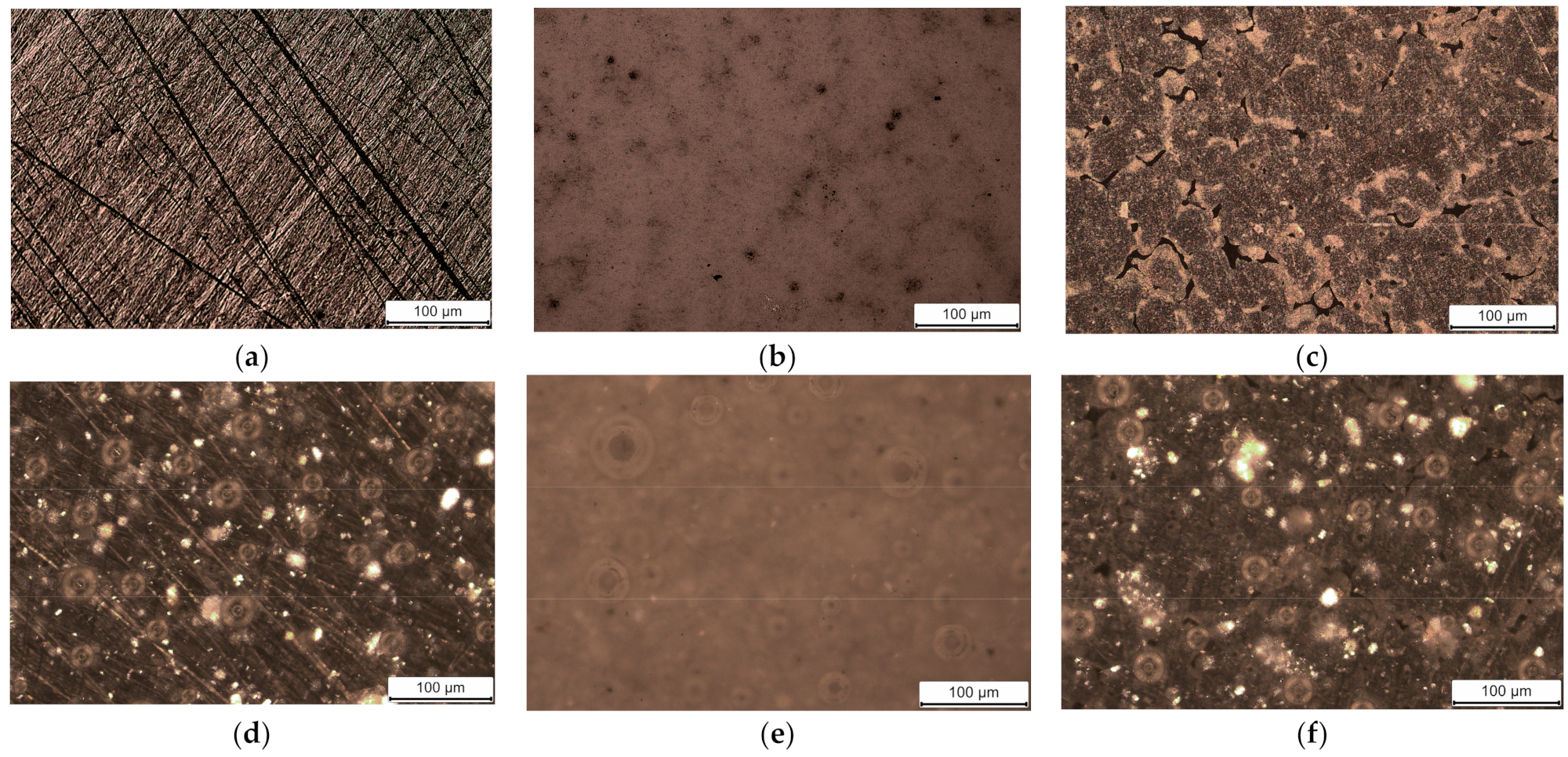
3.1. Morphologies of Coatings

The appearance of the magnesium alloy and all synthesized coatings are shown in Figure 3.
Analyzing the images obtained from an optical microscope of the uncoated AZ91 magnesium alloy, one can notice clear scratches created during the grinding process (Figure 3a). After the alloy surface is anodized in the PEO process, a ceramic coating with external pores is visible. Additionally, darker longitudinal areas can be distinguished in the coating, which are probably oxidized places in the more noble β-phase (Mg17Al12) of the AZ91 alloy (Figure 3b). The surface of the magnesium alloy after chemical conversion does not show visible scratches on the untreated alloy. Furthermore, the appearance of dendritic structures and local cavities can be observed, indicating that a surface modification process has occurred (Figure 3c). In Figure 3d–f, which show the produced UV-cured organic coatings, in all cases spherical areas (i.e., fish eyes) can be seen, indicating the surface imperfection of the powder coatings produced. Because of the transparency of the organic coating, the photos also partially show the structure of the magnesium substrate or the conversion subcoatings.
More detailed images of the magnesium alloy surface and the conversion coatings (without powder organic coating) obtained by the scanning electron microscope are shown in Figure 4. SEM images of AZ91 alloy reveal β-phase regions (lighter areas). On the AP coating, a characteristic of the crater-like structure of the coatings produced in the PEO process can be observed. In the case of the AC coating, apart from clearly visible changes compared to the uncoated alloy, surface cracks and small precipitations are visible.
In order to evaluate the structure, continuity, and adhesion of the coatings, cross-sectional images were taken, which are presented in Figure 5.
Regardless of the conversion coating employed (or its absence), the organic coating is characterized by excellent adhesion to the magnesium substrate and exhibits a continuous structure with no visible delamination, cracks, or gaps between layers. Because of the transparency of the powder coating, small impurities are visible in the volume of the layer. The conversion coating produced in the PEO process (Figure 5e) has a characteristic structure consisting of an outer, thick, and porous layer and an inner, thin, and compact barrier layer. The powder coating applied to this layer fills the open pores of the conversion layer. In the case of a chemically produced conversion coating, the layer is thin and has cracks.

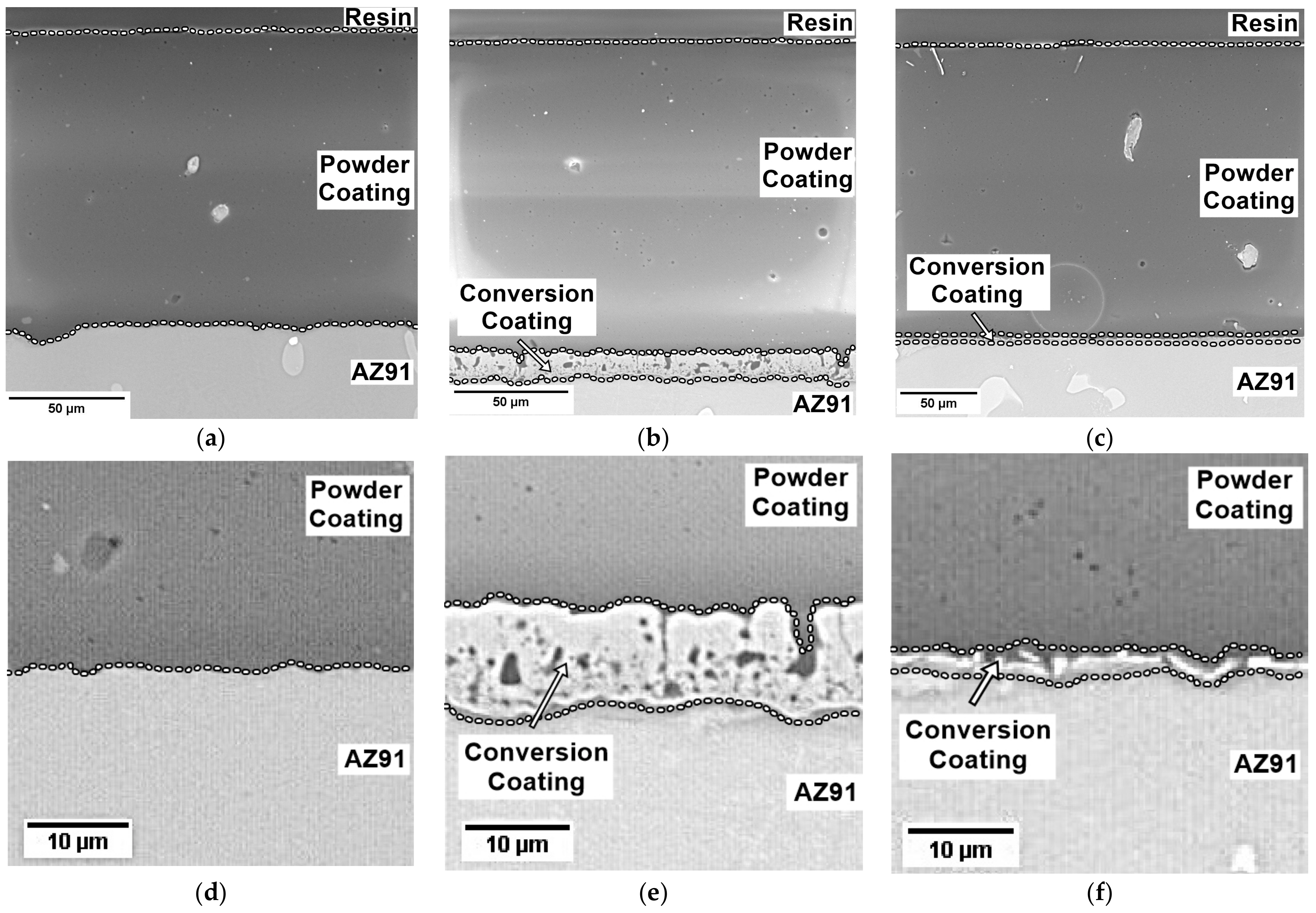
3.2. Thickness and Roughness of Coatings

The coatings were assessed for thickness and roughness. The measurement results are presented in Table 2.
The polished AZ91 magnesium alloy is characterized by low roughness coefficients, which result from the gradation of the SiC paper used. The introduction of chemical treatment (sample AC) slightly increased the coating roughness (from 0.19 to 0.24 μm and from 1.79 to 2.14 μm for Ra and Rz, respectively). On the other hand, PEO treatment (AP) caused more significant changes (Ra = 0.71 μm, Rz = 5.24 μm), which is positive due to the potential increase in the adhesion strength of the organic top layer. The organic powder coating, regardless of the surface on which it was created, is characterized by similar roughness coefficients, which shows that it is a smooth coating (Ra = 0.25–0.27 μm, Rz = 1.47–1.72 μm).
The thickness of the coatings produced on AZ91 magnesium alloy was measured on a macro (thickness gauge) and micro (SEM images) scale. Both techniques obtained similar results, but measurements made with a thickness gauge have a larger standard deviation. The chemical conversion coating (AC) is thin and has a thickness of 0.2–0.3 μm, while the electrochemically produced coating (AP) is thicker (12–13 μm), which is confirmed by SEM images of cross-sections (Figure 5). The thickness range of the organic coating produced on a magnesium substrate is quite large (about 120–180 μm). The corona method employs an electrostatic gun that imparts a negative charge to the powder particle, ensuring that it adheres flawlessly to the grounded metallic substrate, regardless of its roughness. Therefore, the differences in the thickness of the coating are likely due to the manual process of spraying the powder composition. The organic coating produced on a magnesium sample with a chemical conversion layer (ACO) is the thickest (~180 μm), although its roughness is not much different from the coating applied to an untreated magnesium alloy (~120 μm). The powder coating on AZ91 magnesium alloy with conversion produced by the PEO process (APO) has a thickness of approximately 130 μm (not including the conversion layer).

3.3. Chemical Compound of Coatings

The EDS elemental mapping of the coatings is shown in Figure 6, Figure 7 and Figure 8. The element content determined by the EDS for the conversion coatings is presented in Figure 9.
Elemental analysis of the cross-section of the AO sample indicates that the substrate is the alloy consisting of magnesium and aluminum. Aluminum enrichment is visible at the left edge of the image (β-phase fragment) (Figure 6a,c). The powder coating consists of carbon. Small amounts of oxygen (Figure 6e) are visible at the substrate–coating interface, probably from local oxidation of the magnesium alloy in air, before the formation of the organic coating. In the case of the APO coating (Figure 7), between the magnesium substrate and the organic coating, there is a visible conversion layer composed of magnesium and aluminum (which comes from the alloy) and oxygen and silicon (which comes from the electrolyte bath used in the PEO process). Based on reports in the literature, it can be concluded that the resulting conversion coating consists mainly of MgO and SiO2, which may partially combine due to the extreme high temperature in the discharge channel in the plasma process to form Mg2SiO4 [18,48,49]. The cross-section of the ACO coating (Figure 8) exhibits a thin conversion layer enriched with oxide, zirconium, and phosphorus—constituents derived from the chemical conversion bath. In the case of the zircon phosphating magnesium alloy, the presence of Mg3(PO4)2 or MgHPO4·3H2O and ZrO2 can be expected [50,51,52]. Both conversion baths contained fluorine (in the form of NaF or H2ZrF6), making it possible to include it in the structure of the conversion coating, but due to the limitations of the analytical method used, its presence was not detected.
In the elemental distribution cross-sections, the powder coating represents the carbon-containing area. The acrylic resin used to synthesize the UV-cured powder coating is a statistical copolymer composed of three types of mers: glycidyl methacrylate, methyl methacrylate, and n-butyl acrylate (Figure 10). The structure and properties of the resin synthesized and used to cover AZ91 magnesium alloy in this work have been previously examined (using, among others, 1H-NMR and FT-IR spectroscopy) and presented in our work [35].

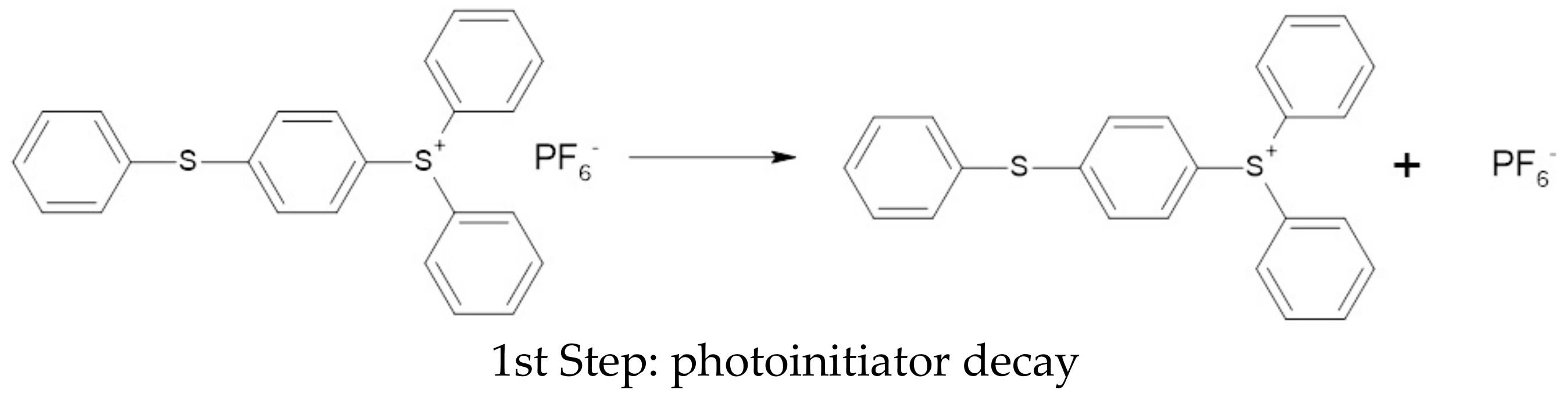
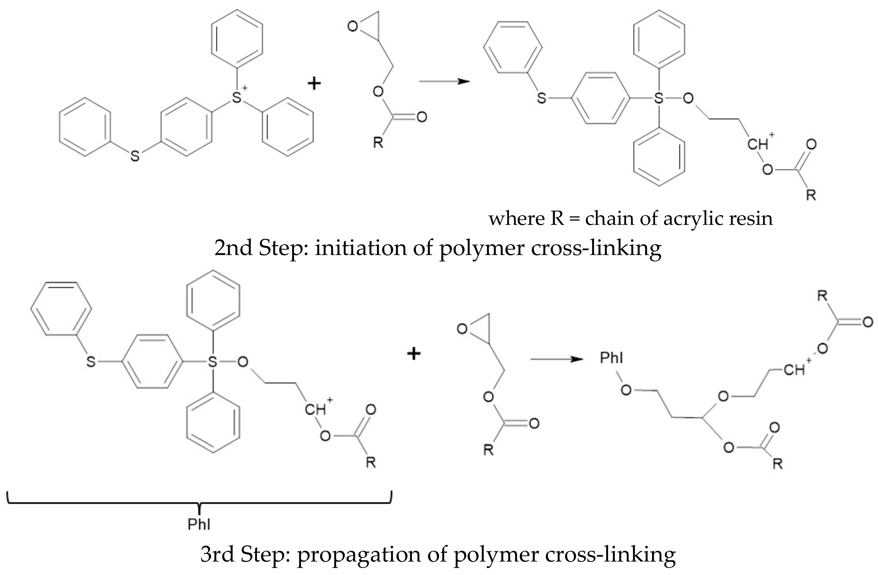
3.4. Polymerization Test of Organic Coating

Each time, a polymerization test was performed to examine the effectiveness of curing powder coatings on a magnesium alloy substrate. None of the tested samples revealed any evidence of coating surface matting or changes in hardness. This means that the UV-curing time used was correctly selected.
In the UV-curing process used, the key issue is the presence of an epoxy group in the acrylic resin, thanks to which the cationic polymerization (cross-linking) reaction of the resin is possible. The polymerization reaction scheme is shown in Figure 11.

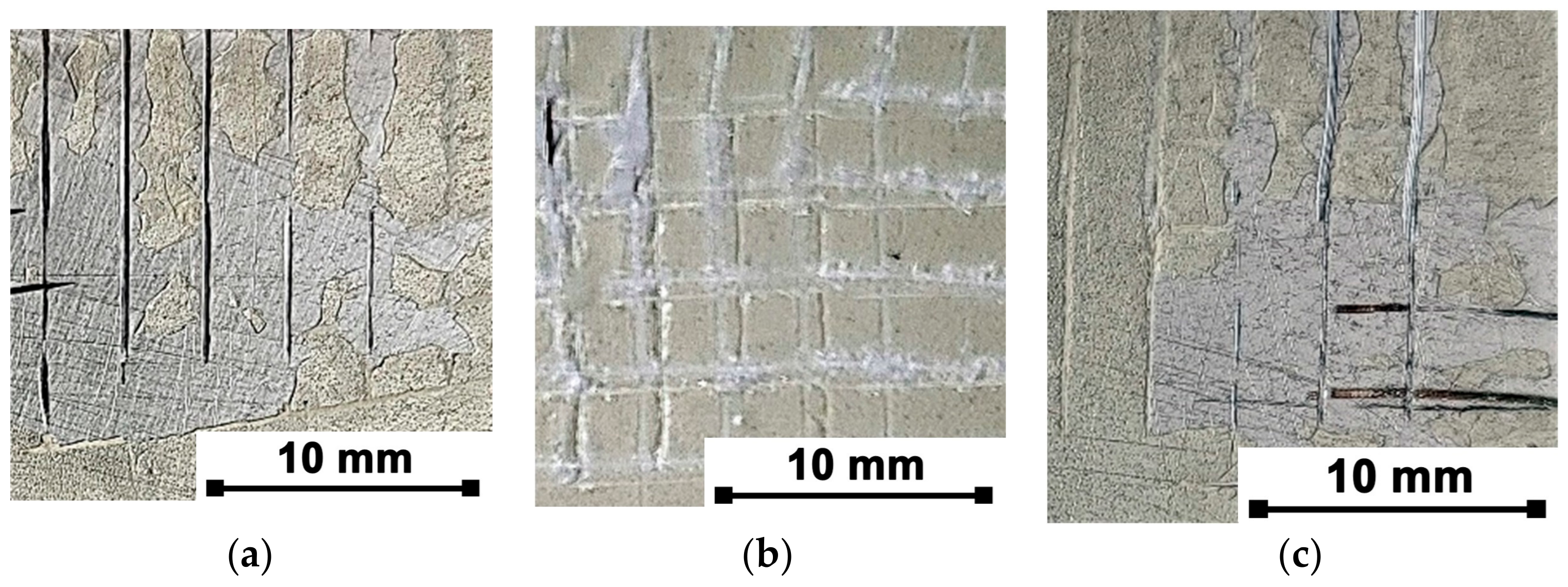
3.5. Adhesive of Organic Coating

Images of the areas subjected to the cross-cut test are shown in Figure 12.
The organic coating applied directly to the magnesium substrate (AO sample) showed very poor adhesion to the substrate (classification 5, according to ISO 2409 [47]—more than 65% of the surface is detached) (Figure 12a). The introduction of a pretreatment in the form of a chemically prepared conversion layer in a commercially available solution resulted in a slight improvement in the adhesion of the top organic coating. The ACO coating (Figure 12c) is flaked along the edges of the cuts in large ribbons and some squares are completely detached (classification 4, according to ISO 2409 [47]—cut grid area damaged in the range of 35–65%). However, the formation of a conversion coating using a plasma electrolytic oxidation method significantly improved the adhesion of the top organic layer. For the APO sample (Figure 12b), only the detachment of small coating flakes is reported at the intersections of the cuts, no more than 5% of the damaged grid surface (classification 1, according to ISO 2409 [47]). The obtained results indicate that the application of a duplex PEO/UV-curable powder coating provided proper protection as a result of high adhesion to the magnesium alloy surface.

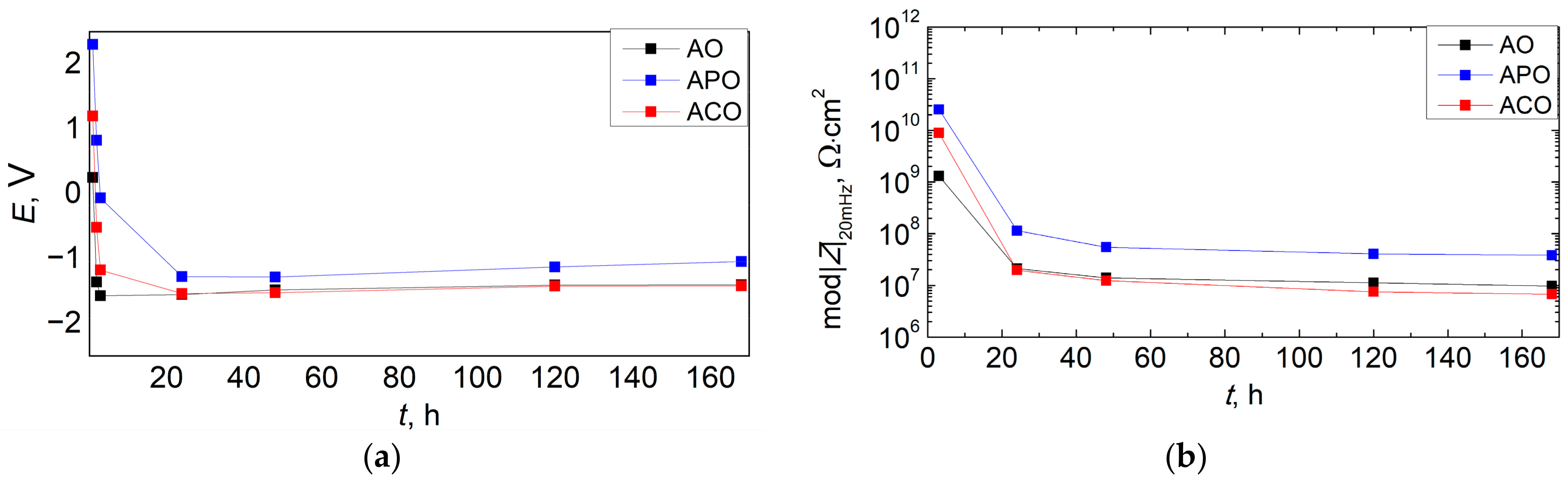
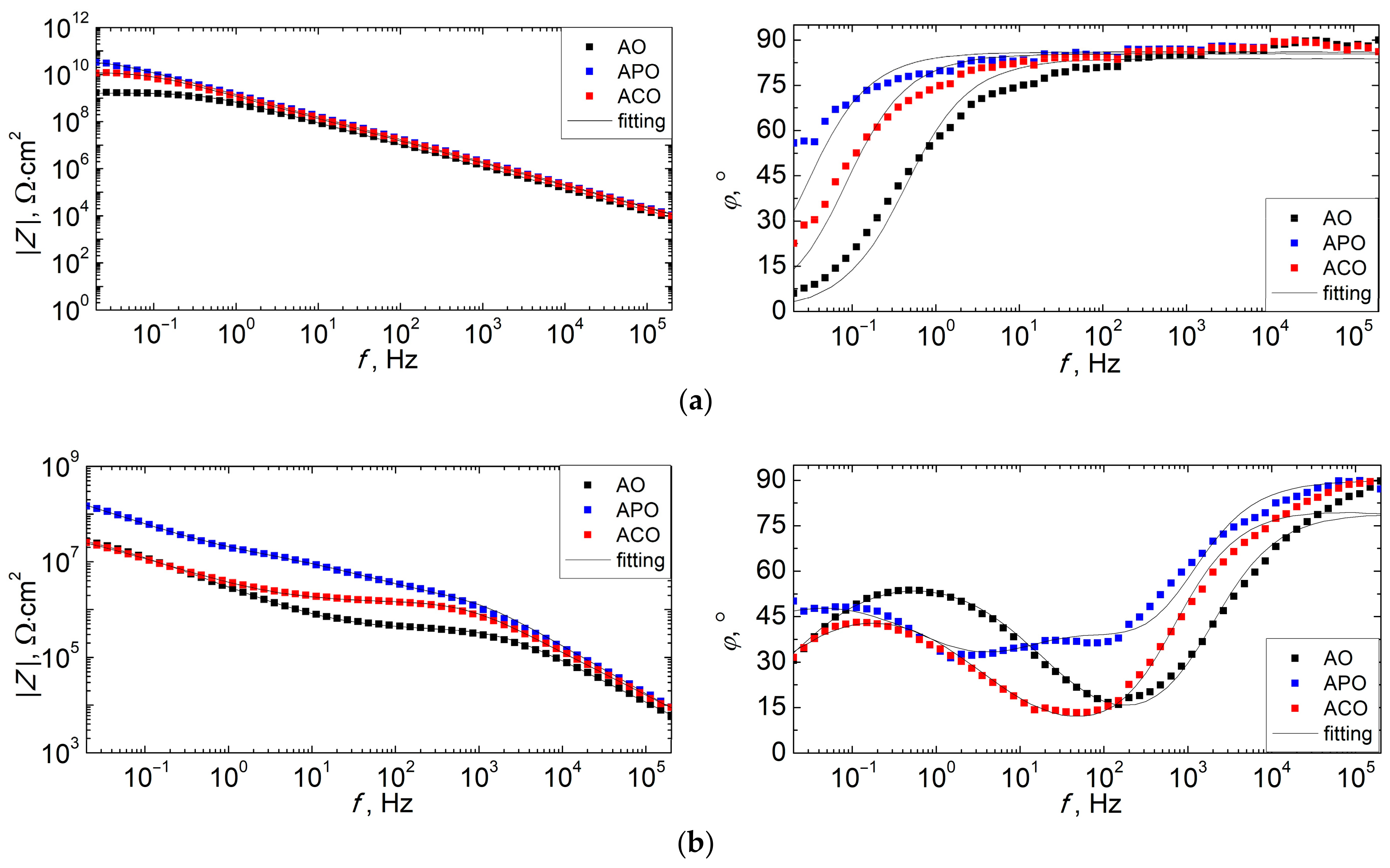
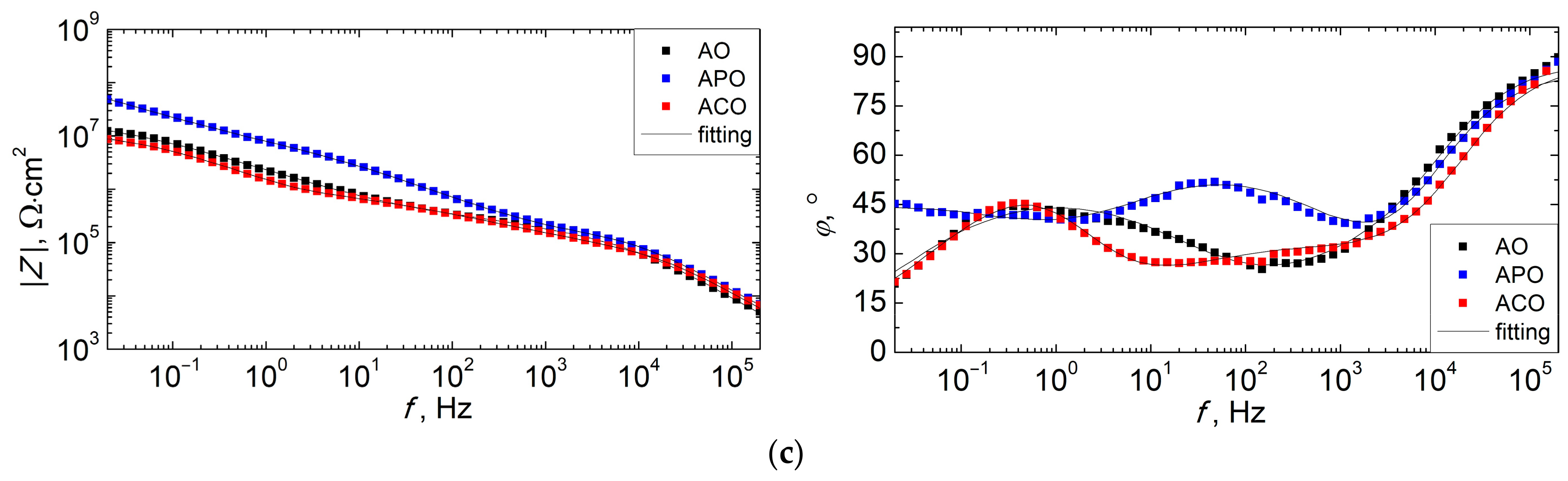
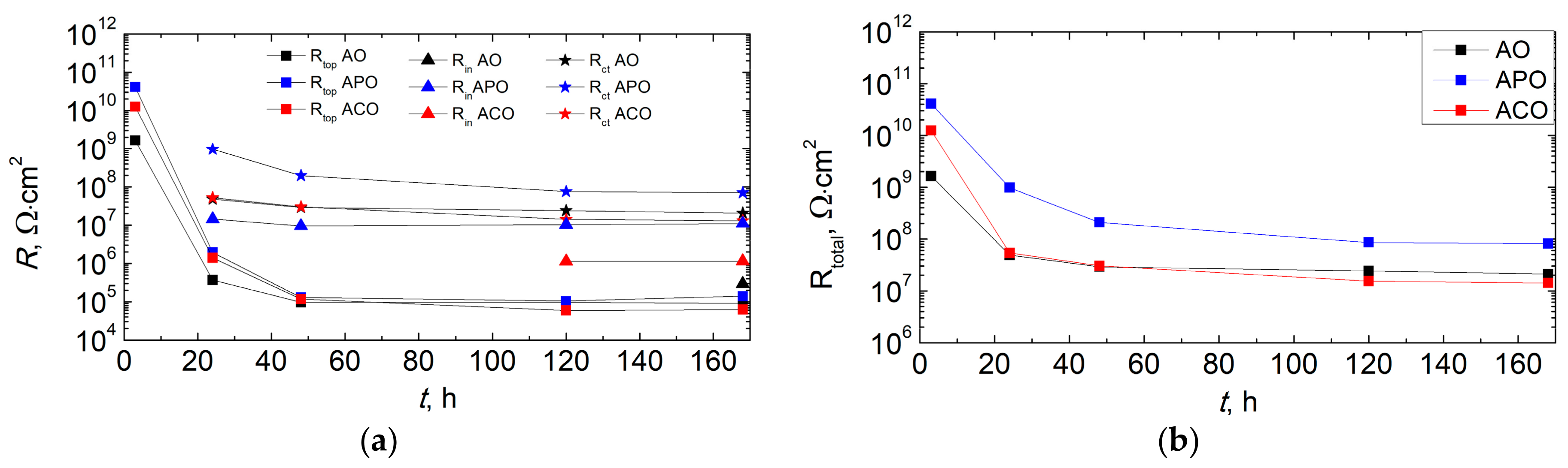
3.6. Corrosion Resistance of Coatings

The UV-cured organic coatings produced on conversion layers and directly on AZ91 magnesium alloy were subjected to impedance tests. Changes in the value of the open circuit potential and the impedance modulus at low frequency (20 mHz) over 7 days of conditioning in a 3.5 wt.% NaCl solution are shown in Figure 13. Figure 14 presents the impedance spectra (Bode plots) of the tested coatings obtained after 3, 24, and 168 h. Furthermore, EIS data were analyzed using an equivalent electrical circuit (EEC) technique using the circuits shown in Figure 15. The good agreement between the experimental data and the fitting results (dots and lines in Figure 14) and the chi-square values obtained were in the range of 0.01–0.001. On the basis of the simulation results obtained, individual resistance values were determined. The total resistance (Rtotal) of the samples calculated as the sum of the resistance components (which results from the structures of the EECs used). The parameters of the equivalent circuits obtained by fitting to the EIS experimental data are presented in Table 3. Furthermore, the values of the determined resistances are shown in Figure 16.
In the initial immersion time (3 h), all samples showed high impedance values (109–1010 Ω·cm2), which means that the organic coating acted as an insulating layer and provided good protective properties. A simple circuit with one capacitive loop was used to analyze the impedance data for an intact organic coating, which included the solution resistance (Rs), the coating capacitance (Qtop), and the coating resistance (Rtop) (model A). Because of the scattering effect caused by the heterogeneity of the coating surface, the constant phase element (Q) was used to replace the capacitance element [53]. The solution resistance, according to calculations, is equal to 12–18 Ω·cm2, but the impedance modulus at high frequencies does not reach this value (Figure 14). The values of the phase angle close to 90° at high and middle frequencies, as well as high values of the power n of the constant phase elements (Table 3), indicate the capacitive character of the Q element. The APO sample had the highest total resistance (41.0 GΩ·cm2); then, the smaller ACO sample (12.5 GΩ·cm2) and the lowest value were obtained for the AO sample (1.6 GΩ·cm2). The same sequence can be observed for the |Z|20mHz value (APO > ACO > AO).
One day after immersion, the impedance spectra became more complicated. For the AO and ACO samples, a second time constant appeared at low-frequency values related to the initiation of substrate corrosion processes. The charge transfer resistance (Rct) and the double-layer capacitance in the form of a constant phase element (Qdl) were included in model B of EEC. In the case of the APO coating, the Bode plot showed an additional maximum of the phase angle at medium-frequency values, proving the influence of the conversion layer created in the PEO process on the measured impedance. The resistance and capacitance of the conversion layer were included in model C as Rin and Qin, respectively. The C model of the equivalent system was also used to fit the impedance spectra for the ACO and AO samples obtained from 120 and 168 h of conditioning in 3.5 wt.% NaCl, respectively. However, in this case, the Rin and Qin elements should be interpreted as related to the corrosion products formed at the interface of the organic coating and the magnesium alloy. The open-circuit potential of all coatings measured 24 h after immersion decreased significantly and stabilized at a range of approximately −1.5 to −1.3 V, close to the free-corrosion potential of the magnesium alloy. The impedances of all samples were also significantly reduced, but this effect was the smallest for the APO sample. The total resistance for this sample was 984.5 MΩ·cm2, while the values for the ACO and AO samples were similar at 53.9 and 48.9 MΩ·cm2, respectively. It should be noted that after this time, the organic coating was saturated with electrolyte, which reduced its resistances (Rtop) to 2.0, 1.4, and 0.4 MΩ·cm2 for the APO, ACO, and AO samples. The total resistance values of the samples were mainly influenced by the charge transfer resistance, which was similar for the ACO and AO samples (52.5 and 48.5 MΩ·cm2, respectively). In the case of the APO sample, the Rct value was much greater (967.9 MΩ·cm2). The resistance value of the conversion coating (Rin) at that time was 14.6 MΩ·cm2. The results show that after 1 day, the APO coating still had much better anticorrosion properties than the other two coatings.
After 48 h of immersion in the corrosive medium, the impedance of the samples decreased further and then stabilized. The resistance of the organic coating for all samples was approximately 0.1 MΩ·cm2. The total resistance of the APO coating was 208.6 MΩ·cm2 and was much higher than that of the AC (30.4 MΩ·cm2) and AO (29.1 MΩ·cm2) coatings.
In the impedance spectra obtained after 168 h for all tested coatings, three components can be distinguished (model 3 of the EEC). The total resistance can be calculated as the sum of Rtop, Rin, and Rct. The total resistance values were 81.6, 14.2, and 21.1 MΩ·cm2 for the APO, ACO, and AO coatings, respectively. It follows that the chemically prepared conversion layer before applying the organic coating did not increase the anticorrosion properties of the obtained ACO coating compared to the AO sample. The use of electrochemical conversion in the PEO process had a completely opposite effect. The APO coating had the highest impedance from the beginning to the end of the corrosion test.
In order to assess the anticorrosion properties of the conversion coatings tested, electrochemical measurements of the uncoated AZ91 magnesium alloy (A sample) and with the conversion coatings produced electrochemically (AP sample) and chemically (AC sample) were made. The results are presented in Figure 17.
On the basis of the results obtained, it can be seen that the OCP values of samples A and AC were similar (approximately −1.55 V). In the case of the AC sample, slightly smaller potential fluctuations were visible. This proves that the chemical conversion had little impact on the alloy surface’s condition. In the case of the sample with an electrochemical conversion layer (i.e., AP sample), a potential shift of about 100 mV to less negative values was observed. However, large potential fluctuations were visible, which was probably the result of local corrosion occurring in the pores of the conversion coating and their sealing with the formed corrosion products. It is a common occurrence when conditioning PEO coatings in aggressive media containing chloride ions. Despite this, during the study period of 24 h, the AP sample exhibited three times higher impedance values (|Z|20mHz of the order of MΩ·cm2) in comparison to samples A and AC. After 60 min of immersion, a chemical conversion coating showed slightly better anticorrosion properties than an uncoated AZ91 alloy. This was probably the result of the presence of a thin phosphate–zirconium layer, which initially limited the corrosion rate of the magnesium substrate. With prolonged conditioning in a corrosive medium, the impedance of the AC coating decreased and was marginally lower than that of sample A.
The corrosion resistance results obtained for conversion coatings alone were proportional to the measurements of the coating systems (conversion layer + organic layer). The conversion coating produced in the PEO process allowed for an improvement in the anticorrosion properties of the duplex PEO/UV-curable powder coating compared to the organic coating produced directly on the magnesium alloy. The presence of a conversion coating produced by a chemical process had a positive effect on the initial corrosion resistance, but in the long term it turned out to be ineffective in protecting the magnesium substrate.

4. Conclusions

In the presented study, the procedure for the synthesis of a duplex PEO/UV-curable powder coating on AZ91 magnesium alloy has been described. The synthesized coating system was evaluated in terms of morphology, adhesion (mesh of cuts), and anticorrosion properties. The obtained results were compared with those of a powder coating synthesized directly on a magnesium substrate and an alternative conversion coating created by a chemical zircon phosphating process. The results can be summarized as follows:
  • Regardless of the presence or absence of a conversion coating on the magnesium alloy, the powder coating was successfully cured by UV radiation. The organic coating adhered well to all surfaces, its thickness was in the range of 120–180 μm, and its roughnesses were similar in all cases.
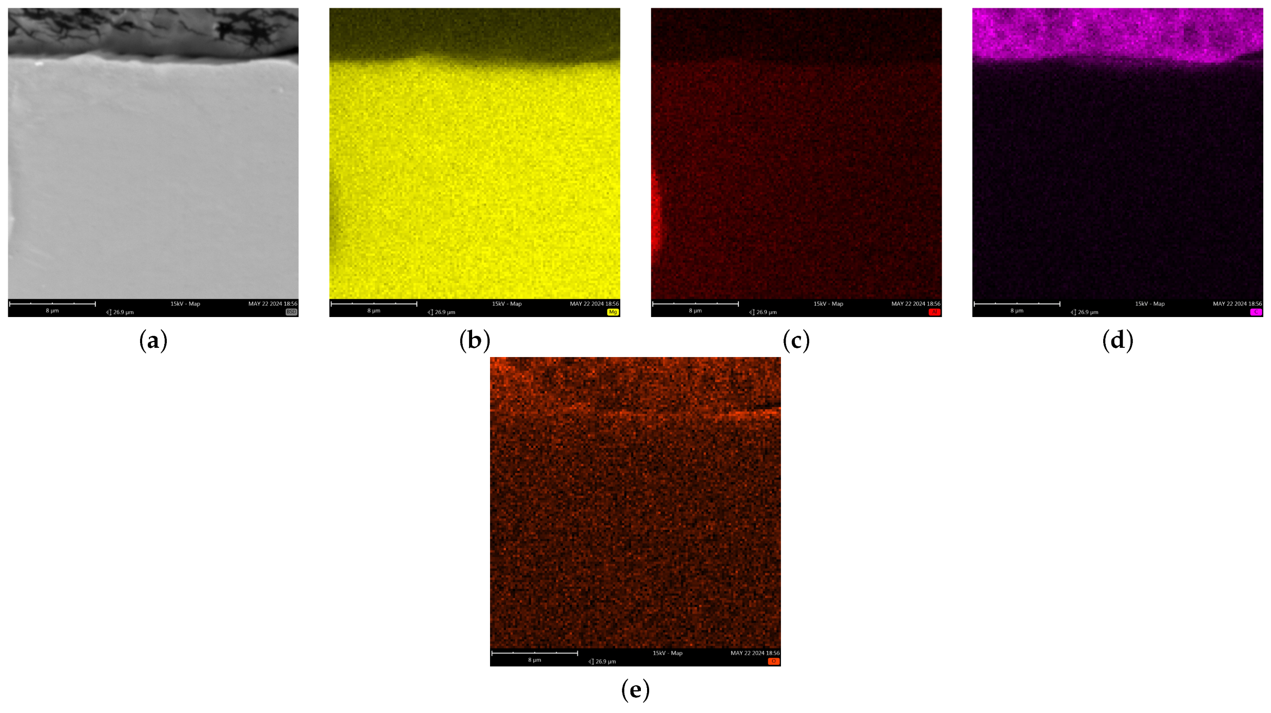
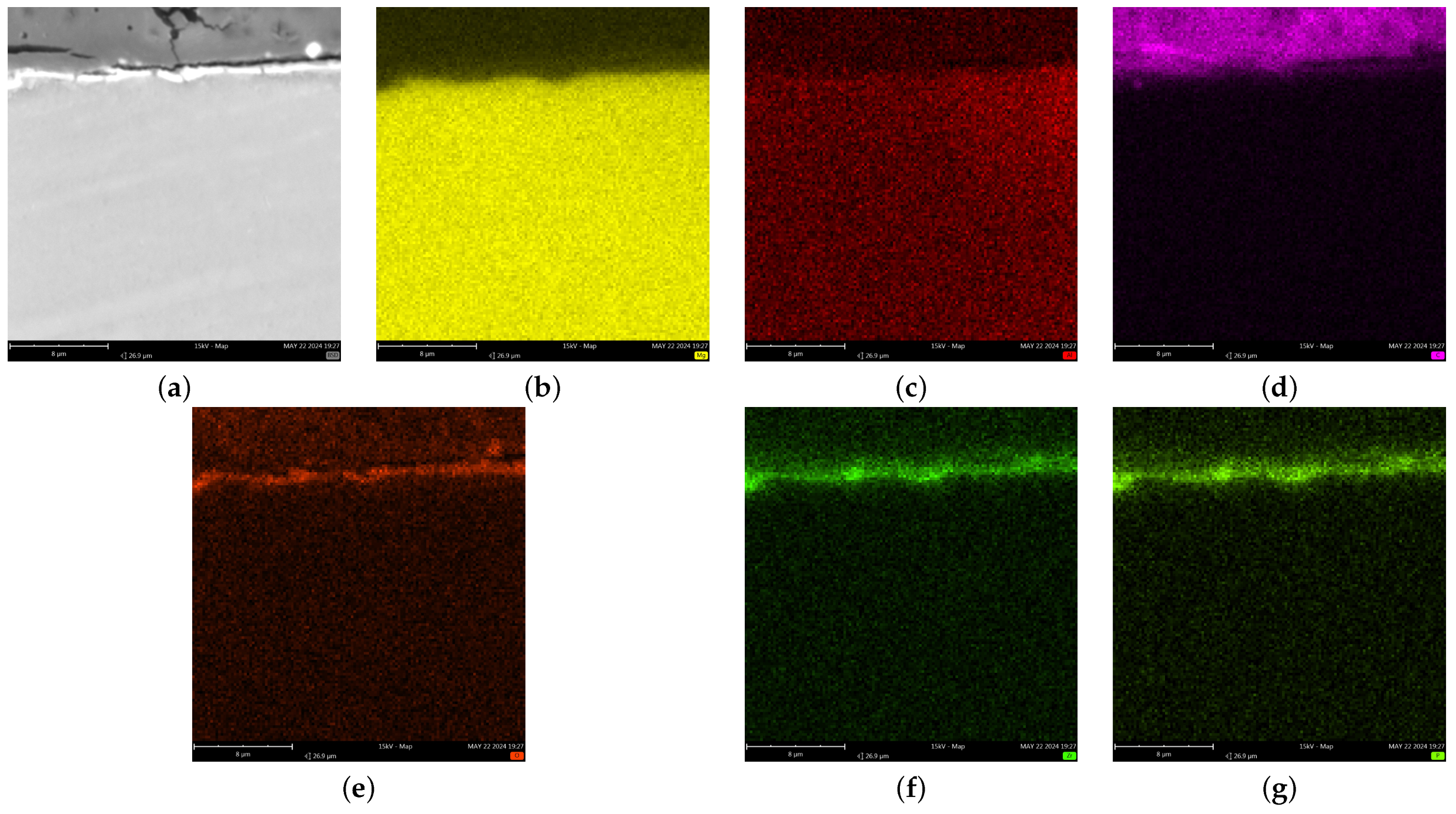
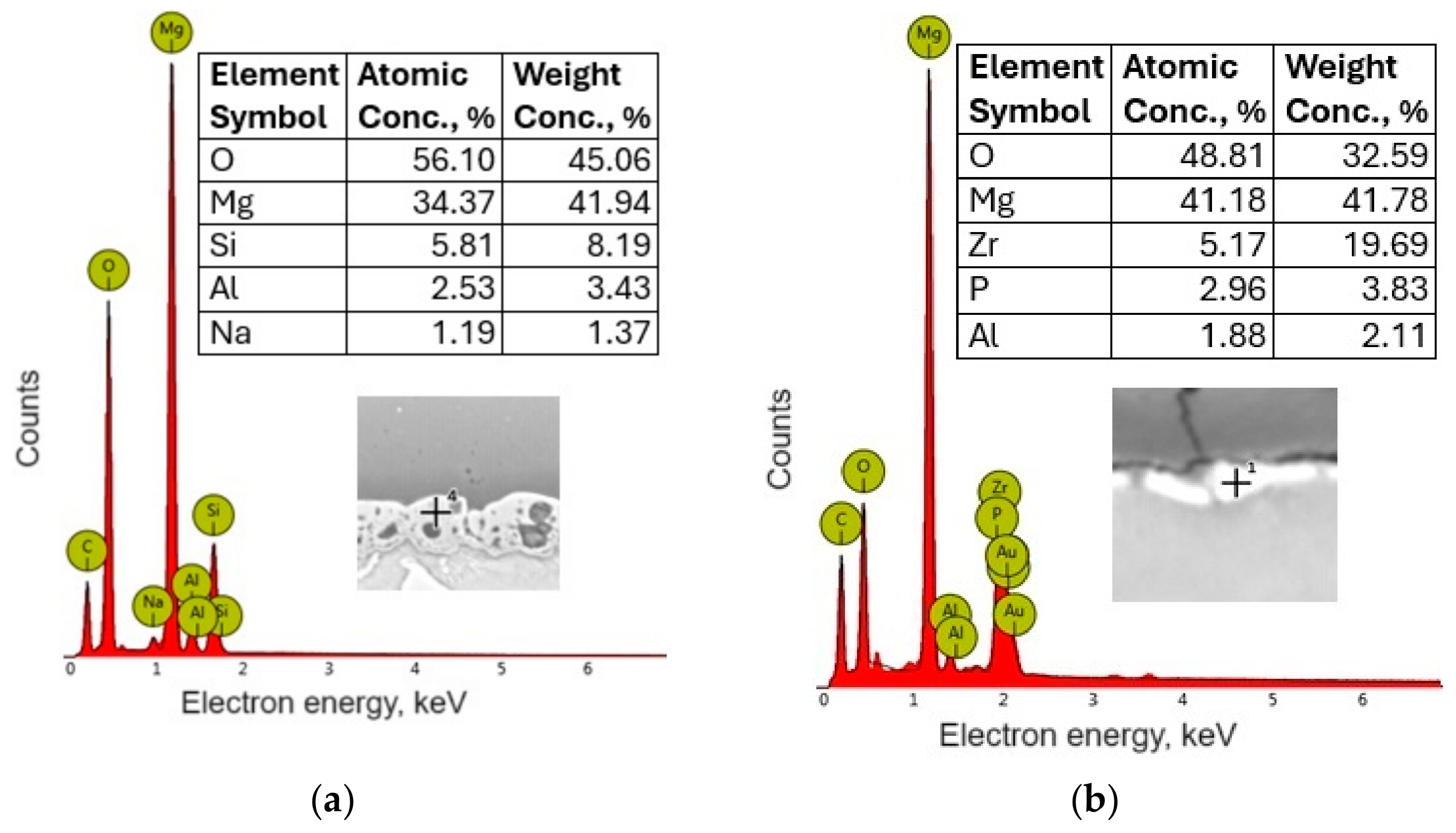
  • The synthesis of conversion coatings was successful. The coating produced in the PEO process had a thickness of approximately 12–13 μm, was continuous, and had a characteristic crater-like surface morphology. It was composed mainly of Mg, O, and Si. The conversion coating produced from the zircon phosphate bath had a thickness of 0.2–0.3 μm and cracked in places. It was composed of Mg, O, P, and Zr.
  • The formation of a conversion coating in the PEO process significantly increased the adhesion of the powder coating to the magnesium substrate. The use of chemical conversion had a negligible effect.
  • The duplex PEO/UV-curable powder coating showed significantly improved anticorrosion properties compared to other systems (chemical conversion + powder coating and only powder coating). Chemical conversion from the zircon phosphate bath initially increased the impedance of the sample (compared to the coating produced directly on the magnesium alloy), but in the long term (168 h), it did not have a positive effect on the anticorrosion properties.

Author Contributions

Conceptualization, Ł.F. and B.P.-P.; methodology, Ł.F. and K.P.; validation, Ł.F., K.P. and B.P.-P.; formal analysis, Ł.F., K.P. and B.K.; investigation, Ł.F., K.P. and B.K.; data curation, Ł.F., K.P. and B.K.; writing—original draft preparation, Ł.F.; visualization, Ł.F. and K.P.; writing—review and editing, K.P., B.K. and B.P.-P.; supervision, B.P.-P. All authors have read and agreed to the published version of the manuscript.

Funding

This research was funded by Rzeszow University of Technology within a PB25.CF.24.001 grant.

Data Availability Statement

The raw data supporting the conclusions of this article will be made available by the authors on request.

Conflicts of Interest

The authors declare no conflicts of interest.

References

  1. Yang, Y.; Xiong, X.; Chen, J.; Peng, X.; Chen, D.; Pan, F. Research advances of magnesium and magnesium alloys worldwide in 2022. J. Magnes. Alloys 2023, 11, 2611–2654. [Google Scholar] [CrossRef]
  2. Liu, B.; Yang, J.; Zhang, X.; Yang, Q.; Zhang, J.; Li, X. Development and application of magnesium alloy parts for automotive OEMs: A review. J. Magnes. Alloys 2023, 11, 15–47. [Google Scholar] [CrossRef]
  3. Bai, J.; Yang, Y.; Wen, C.; Chen, J.; Zhou, G.; Jiang, B.; Peng, X.; Pan, F. Applications of magnesium alloys for aerospace: A review. J. Magnes. Alloys 2023, 11, 3609–3619. [Google Scholar] [CrossRef]
  4. Zan, R.; Shen, S.; Huang, Y.; Yu, H.; Liu, Y.; Yang, S.; Zheng, B.; Gong, Z.; Wang, W.; Zhang, X.; et al. Research hotspots and trends of biodegradable magnesium and its alloys. Smart Mater. Med. 2023, 4, 468–479. [Google Scholar] [CrossRef]
  5. Sharma, S.K.; Saxena, K.K.; Malik, V.; Mohammed, K.A.; Prakash, C.; Buddhi, D.; Dixit, S. Significance of Alloying Elements on the Mechanical Characteristics of Mg-Based Materials for Biomedical Applications. Crystals 2022, 12, 1138. [Google Scholar] [CrossRef]
  6. Rong-Chang, Z.; Zheng-Zheng, Y.; Xiao-Bo, C.; Dao-Kui, X. Corrosion Types of Magnesium Alloys. In Magnesium Alloys; Tomasz, T., Wojciech, B., Mariusz, K., Eds.; IntechOpen: Rijeka, Croatia, 2018; p. Ch. 3. [Google Scholar]
  7. Xu, L.; Liu, X.; Sun, K.; Fu, R.; Wang, G. Corrosion Behavior in Magnesium-Based Alloys for Biomedical Applications. Materials 2022, 15, 2613. [Google Scholar] [CrossRef] [PubMed]
  8. Song, G.-L.; Atrens, A. Recently deepened insights regarding Mg corrosion and advanced engineering applications of Mg alloys. J. Magnes. Alloys 2023, 11, 3948–3991. [Google Scholar] [CrossRef]
  9. Liu, H.; Cao, F.; Song, G.-L.; Zheng, D.; Shi, Z.; Dargusch, M.S.; Atrens, A. Review of the atmospheric corrosion of magnesium alloys. J. Mater. Sci. Technol. 2019, 35, 2003–2016. [Google Scholar] [CrossRef]
  10. Gray, J.E.; Luan, B. Protective coatings on magnesium and its alloys—A critical review. J. Alloys Compd. 2002, 336, 88–113. [Google Scholar] [CrossRef]
  11. Predko, P.; Rajnovic, D.; Grilli, M.L.; Postolnyi, B.O.; Zemcenkovs, V.; Rijkuris, G.; Pole, E.; Lisnanskis, M. Promising Methods for Corrosion Protection of Magnesium Alloys in the Case of Mg-Al, Mg-Mn-Ce and Mg-Zn-Zr: A Recent Progress Review. Metals 2021, 11, 1133. [Google Scholar] [CrossRef]
  12. Wu, T.; Zhang, K. Corrosion and Protection of Magnesium Alloys: Recent Advances and Future Perspectives. Coatings 2023, 13, 1533. [Google Scholar] [CrossRef]
  13. Barati Darband, G.; Aliofkhazraei, M.; Hamghalam, P.; Valizade, N. Plasma electrolytic oxidation of magnesium and its alloys: Mechanism, properties and applications. J. Magnes. Alloys 2017, 5, 74–132. [Google Scholar] [CrossRef]
  14. Florczak, Ł.; Nawrat, G.; Kwolek, P.; Sieniawski, J.; Sobkowiak, A. Plasma electrolytic oxidation as a method for protection against corrosion of magnesium and its alloys. Przemysł Chem. 2018, 97, 2145–2153. (In Polish) [Google Scholar] [CrossRef]
  15. Kaseem, M.; Fatimah, S.; Nashrah, N.; Ko, Y.G. Recent progress in surface modification of metals coated by plasma electrolytic oxidation: Principle, structure, and performance. Prog. Mater. Sci. 2021, 117, 100735. [Google Scholar] [CrossRef]
  16. Yao, W.; Wu, L.; Wang, J.; Jiang, B.; Zhang, D.; Serdechnova, M.; Shulha, T.; Blawert, C.; Zheludkevich, M.L.; Pan, F. Micro-arc oxidation of magnesium alloys: A review. J. Mater. Sci. Technol. 2022, 118, 158–180. [Google Scholar] [CrossRef]
  17. Yang, C.; Chen, P.; Wu, W.; Sheng, L.; Zheng, Y.; Chu, P.K. A Review of Corrosion-Resistant PEO Coating on Mg Alloy. Coatings 2024, 14, 451. [Google Scholar] [CrossRef]
  18. Wierzbicka, E.; Vaghefinazari, B.; Mohedano, M.; Visser, P.; Posner, R.; Blawert, C.; Zheludkevich, M.; Lamaka, S.; Matykina, E.; Arrabal, R. Chromate-Free Corrosion Protection Strategies for Magnesium Alloys—A Review: Part II—PEO and Anodizing. Materials 2022, 15, 8515. [Google Scholar] [CrossRef] [PubMed]
  19. Regulation (EC) No 1907/2006 of the European Parliament and of the Council of 18 December 2006 concerning the Registration, Evaluation, Authorisation and Restriction of Chemicals (REACH), Establishing a European Chemicals Agency, amending DIRECTIVE 1999/45/EC and Repealing Council Regulation (EEC) No 793/93 and Commission Regulation (EC) No 1488/94 as well as Council Directive 76/769/EEC and Commission Directives 91/155/EEC, 93/67/EEC, 93/105/EC and 2000/21/EC. Available online: https://eur-lex.europa.eu/eli/reg/2006/1907/oj (accessed on 16 June 2024).
  20. Sikdar, S.; Menezes, P.V.; Maccione, R.; Jacob, T.; Menezes, P.L. Plasma Electrolytic Oxidation (PEO) Process—Processing, Properties, and Applications. Nanomaterials 2021, 11, 1375. [Google Scholar] [CrossRef] [PubMed]
  21. Alateyah, A.I.; Aljohani, T.A.; Alawad, M.O.; Elkatatny, S.; El-Garaihy, W.H. Improving the Corrosion Behavior of Biodegradable AM60 Alloy through Plasma Electrolytic Oxidation. Metals 2021, 11, 953. [Google Scholar] [CrossRef]
  22. Florczak, Ł.; Nawrat, G.; Darowicki, K.; Ryl, J.; Sieniawski, J.; Wierzbińska, M.; Raga, K.; Sobkowiak, A. The Effect of Sodium Tetrafluoroborate on the Properties of Conversion Coatings Formed on the AZ91D Magnesium Alloy by Plasma Electrolytic Oxidation. Processes 2022, 10, 2089. [Google Scholar] [CrossRef]
  23. Lujun, Z.; Hongzhan, L.; Qingmei, M.; Jiangbo, L.; Zhengxian, L. The mechanism for tuning the corrosion resistance and pore density of plasma electrolytic oxidation (PEO) coatings on Mg alloy with fluoride addition. J. Magnes. Alloys 2023, 11, 2823–2832. [Google Scholar] [CrossRef]
  24. Florczak, Ł.; Kościelniak, B.; Kramek, A.; Sobkowiak, A. The Influence of Potassium Hexafluorophosphate on the Morphology and Anticorrosive Properties of Conversion Coatings Formed on the AM50 Magnesium Alloy by Plasma Electrolytic Oxidation. Materials 2023, 16, 7573. [Google Scholar] [CrossRef] [PubMed]
  25. Xie, P.; Blawert, C.; Serdechnova, M.; Konchakova, N.; Shulha, T.; Wu, T.; Zheludkevich, M.L. Effect of low concentration electrolytes on the formation and corrosion resistance of PEO coatings on AM50 magnesium alloy. J. Magnes. Alloys 2024, 12, 1386–1405. [Google Scholar] [CrossRef]
  26. Hu, R.-G.; Zhang, S.; Bu, J.-F.; Lin, C.-J.; Song, G.-L. Recent progress in corrosion protection of magnesium alloys by organic coatings. Prog. Org. Coat. 2012, 73, 129–141. [Google Scholar] [CrossRef]
  27. Directive 2004/42/EC of the European Parliament and of the Council of 21 April 2004 on the Limitation of Emissions of volatile Organic Compounds due to the Use of Organic Solvents in Certain Paints and Varnishes and Vehicle Refinishing Products and Amending Directive 1999/13/EC. Available online: https://eur-lex.europa.eu/eli/dir/2004/42/oj (accessed on 16 June 2024).
  28. Spyrou, E. Powder Coatings Chemistry and Technology; Vincentz Network: Hannover, Germany, 2014. [Google Scholar]
  29. Poth, U.; Schwalm, R.; Schwartz, M.; Baunstark, R. Acrylic Resins; Vincentz Network: Hanover, Germany, 2011. [Google Scholar]
  30. Pojnar, K.; Pilch-Pitera, B.; Patil, R. Progress in the development of acrylic resin-based powder coatings—An overview. Polimery 2024, 69, 143–158. [Google Scholar] [CrossRef]
  31. Yagci, Y.; Jockusch, S.; Turro, N.J. Photoinitiated Polymerization: Advances, Challenges, and Opportunities. Macromolecules 2010, 43, 6245–6260. [Google Scholar] [CrossRef]
  32. Deng, L.; Tang, L.; Qu, J. Synthesis and photopolymerization of novel UV-curable macro-photoinitiators. Prog. Org. Coat. 2020, 141, 105546. [Google Scholar] [CrossRef]
  33. Czachor-Jadacka, D.; Pilch-Pitera, B.; Kisiel, M.; Gumieniak, J. Hydrophobic UV-Curable Powder Clear Coatings: Study on the Synthesis of New Crosslinking Agents Based on Raw Materials Derived from Renewable Sources. Materials 2021, 14, 4710. [Google Scholar] [CrossRef] [PubMed]
  34. Hammer, T.J.; Mehr, H.M.S.; Pugh, C.; Soucek, M.D. Urethane methacrylate reactive diluents for UV-curable polyester powder coatings. J. Coat. Technol. Res. 2021, 18, 333–348. [Google Scholar] [CrossRef]
  35. Pojnar, K.; Pilch-Pitera, B.; Kisiel, M.; Zioło, A.; Kędzierski, M. UV-curable powder transparent coatings based on oligo(meth)acrylic resins. Polimery 2024, 69, 11–24. [Google Scholar] [CrossRef]
  36. Rawat, R.S.; Chouhan, N.; Talwar, M.; Diwan, R.K.; Tyagi, A.K. UV coatings for wooden surfaces. Prog. Org. Coat. 2019, 135, 490–495. [Google Scholar] [CrossRef]
  37. Lukac, P.; Trojanova, Z. Mechanical Properties of Az91 Magnesium Alloys. Commun. Sci. Lett. Univ. Zilina 2004, 6, 26–29. [Google Scholar] [CrossRef]
  38. Xiulan, A.; Gaofeng, Q. The Recent Research on Properties of Anti-High Temperature Creep of AZ91 Magnesium Alloy. In Magnesium Alloys; Frank, C., Ed.; IntechOpen: Rijeka, Croatia, 2011; p. Ch. 16. [Google Scholar]
  39. Zimina, M.; Malek, P.; Bohlen, J.; Letzig, D.; Kurz, G.; Cieslar, M. Mechanical properties of homogenized twin-roll cast and conventionally cast AZ31 magnesium alloys. Mater. Eng. 2015, 22, 8–15. [Google Scholar]
  40. Gnedenkov, A.S.; Sinebryukhov, S.L.; Filonina, V.S.; Ustinov, A.Y.; Gnedenkov, S.V. Hybrid Coatings for Active Protection against Corrosion of Mg and Its Alloys. Polymers 2023, 15, 3035. [Google Scholar] [CrossRef] [PubMed]
  41. Yao, W.; Liang, W.; Huang, G.; Jiang, B.; Atrens, A.; Pan, F. Superhydrophobic coatings for corrosion protection of magnesium alloys. J. Mater. Sci. Technol. 2020, 52, 100–118. [Google Scholar] [CrossRef]
  42. Farshid, S.; Kharaziha, M. Micro and nano-enabled approaches to improve the performance of plasma electrolytic oxidation coated magnesium alloys. J. Magnes. Alloys 2021, 9, 1487–1504. [Google Scholar] [CrossRef]
  43. Fattah-alhosseini, A.; Chaharmahali, R.; Babaei, K. Impressive strides in amelioration of corrosion and wear behaviors of Mg alloys using applied polymer coatings on PEO porous coatings: A review. J. Magnes. Alloys 2022, 10, 1171–1190. [Google Scholar] [CrossRef]
  44. Li, N.; Ling, N.; Fan, H.; Wang, L.; Zhang, J. Self-healing and superhydrophobic dual-function composite coating for active protection of magnesium alloys. Surf. Coat. Technol. 2023, 454, 129146. [Google Scholar] [CrossRef]
  45. ASTM B94; Standard Specification for Magnesium-Alloy Die Castings. ASTM International: West Conshohocken, PA, USA, 2009.
  46. Bellot, P. Specifications for a Quality Label for Liquid and Powder Coatings on Aluminium for Architectural Applications; QUALICOAT Specifications: Zurich, Switzerland, 2024. [Google Scholar]
  47. PN-EN ISO 2409; Paints and Varnishes—Cross-Cut Testing. International Organization for Standardization: Geneva, Switzerland, 2013. (In Polish)
  48. Liu, J.; Lu, Y.; Jing, X.; Yuan, Y.; Zhang, M. Characterization of plasma electrolytic oxidation coatings formed on Mg–Li alloy in an alkaline silicate electrolyte containing silica sol. Mater. Corros. 2009, 60, 865–870. [Google Scholar] [CrossRef]
  49. Aktuğ, S.L.; Durdu, S.; Kutbay, I.; Usta, M. Effect of Na2SiO3·5H2O concentration on microstructure and mechanical properties of plasma electrolytic oxide coatings on AZ31 Mg alloy produced by twin roll casting. Ceram. Int. 2016, 42, 1246–1253. [Google Scholar] [CrossRef]
  50. Hafeez, M.A.; Farooq, A.; Zang, A.; Saleem, A.; Deen, K.M. Phosphate chemical conversion coatings for magnesium alloys: A review. J. Coat. Technol. Res. 2020, 17, 827–849. [Google Scholar] [CrossRef]
  51. Yi, A.; Du, J.; Wang, J.; Mu, S.; Zhang, G.; Li, W. Preparation and characterization of colored Ti/Zr conversion coating on AZ91D magnesium alloy. Surf. Coat. Technol. 2015, 276, 239–247. [Google Scholar] [CrossRef]
  52. Vaghefinazari, B.; Wierzbicka, E.; Visser, P.; Posner, R.; Arrabal, R.; Matykina, E.; Mohedano, M.; Blawert, C.; Zheludkevich, M.; Lamaka, S. Chromate-Free Corrosion Protection Strategies for Magnesium Alloys—A Review: PART I—Pre-Treatment and Conversion Coating. Materials 2022, 15, 8676. [Google Scholar] [CrossRef] [PubMed]
  53. Fandi, M.; Li, L. Electrochemical Evaluation Technologies of Organic Coatings. In Coatings and Thin-Film Technologies; Jaime Andres, P.-T., Alba, G.A.B., Eds.; IntechOpen: Rijeka, Croatia, 2018; p. Ch. 3. [Google Scholar]
Figure 1. PEO process: (a) shape of a single current pulse; (b) voltage–time curve; (c) appearance of the sample during the process.
Metals 14 00733 g001
Figure 2. Scheme of the stages of obtaining UV-cured powder coatings on magnesium substrates.
Metals 14 00733 g002
Figure 3. Optical microscope images: (a) uncoated AZ91 magnesium alloy; coatings: (b) AP, (c) AC, (d) AO, (e) APO, (f) ACO.
Metals 14 00733 g003
Figure 4. SEM images: (a) uncoated AZ91 magnesium alloy; conversion coatings: (b) AP and (c) AC.
Metals 14 00733 g004
Figure 5. SEM images showing cross-sections of the coatings: (a,d) AO; (b,e) APO; (c,f) ACO.
Metals 14 00733 g005
Figure 6. The elemental distribution in the cross-section of the AO coating: (a) SEM image; EDS mappings of (b) Mg, (c) Al, (d) C, (e) O.
Metals 14 00733 g006
Figure 7. The elemental distribution in the cross-section of the APO coating: (a) SEM image; EDS mappings of (b) Mg, (c) Al, (d) C, (e) O, (f) Si.
Metals 14 00733 g007
Figure 8. The elemental distribution in the cross-section of the ACO coating: (a) SEM image; EDS mappings of (b) Mg, (c) Al, (d) C, (e) O, (f) Zr, (g) P.
Metals 14 00733 g008
Figure 9. EDS spectrum and chemical composition of the conversion coatings: (a) AP; (b) AC. The values given in the tables were determined from the points marked 4 and 1, respectively.
Metals 14 00733 g009
Figure 10. Structure of acrylic resin (GMA—glycidyl methacrylate, MMA—methyl methacrylate, and BA—n-butyl acrylate).
Metals 14 00733 g010
Figure 11. Scheme of photoinitiated reaction of UV-curing-powder coatings based on acrylic resin.
Metals 14 00733 g011aMetals 14 00733 g011b
Figure 12. Photos of coating surfaces after the cross-cut test: (a) AO; (b) APO; (c) ACO.
Metals 14 00733 g012
Figure 13. Results of the electrochemical measurements of AO, APO, and ACO coatings: (a) open circuit potential; (b) impedance modulus at 20 mHz.
Metals 14 00733 g013
Figure 14. Bode plots of AO, APO, and ACO coatings made after the following immersion times: (a) 3 h; (b) 24 h; (c) 168 h.
Metals 14 00733 g014aMetals 14 00733 g014b
Figure 15. Equivalent electrical circuits used to fit the EIS data.
Metals 14 00733 g015
Figure 16. Resistance values obtained from the fitting of the EIS experimental data for AO, APO, and ACO coatings: (a) Rtop, Rin, and Rct; (b) Rtotal.
Metals 14 00733 g016
Figure 17. Results of the corrosion measurements of the AZ91 magnesium alloy uncoated and with a conversion coating: (a) open circuit potential; (b) impedance modulus at 20 mHz.
Metals 14 00733 g017
Table 1. Code name of samples.
Code NameSubstrateTreatment
AAZ91Uncoated
AP Electrochemical conversion (in PEO process)
ACChemical conversion (in Eskaphor Z 2000 C solution)
AOOrganic coating (in UV-curable powder coating)
APOElectrochemical conversion + organic coating
ACOChemical conversion + organic coating
Table 2. Average layer thickness and surface roughness coefficients of samples.
Sampled1 [μm]d2 [μm]Ra [μm]Rz [μm]
A--0.19 ± 0.021.79 ± 0.22
AP12.2 ± 0.313.12 ± 0.940.71 ± 0.025.24 ± 0.40
AC0.2 ± 0.10.33 ± 0.030.24 ± 0.022.14 ± 0.23
AO126.0 ± 5.0120.40 ± 1.430.25 ± 0.041.54 ± 0.57
APO138.0 ± 29.0149.30 ± 2.830.25 ± 0.051.47 ± 0.34
ACO178.0 ± 24.0187.10 ± 1.100.27 ± 0.061.72 ± 0.42
d1—Result from thickness gauge (eddy current method); d2—result from SEM images of the cross-section.
Table 3. EIS fitting parameters for samples.
SampleTime,
h
Qtop,
Fn/cm2
ntopRtop,
Ω·cm2
Qin,
Fn/cm2
ninRin,
Ω·cm2
Qdl,
Fn/cm2
ndlRct,
Ω·cm2
AO32.36 × 10−100.9311.64 × 109
245.75 × 10−100.9013.73 × 105 9.94 × 10−80.6884.85 × 107
1682.25 × 10−100.9809.06 × 1043.75 × 10−80.5752.96 × 1051.09 × 10−70.5982.08 × 107
APO31.22 × 10−100.9554.10 × 1010
249.17 × 10−110.9521.96 × 1065.24 × 10−90.6621.46 × 1071.82 × 10−80.6269.68 × 108
1682.37 × 10−100.9511.38 × 1052.06 × 10−80.6581.11 × 1074.22 × 10−80.7247.04 × 107
ACO31.45 × 10−100.9491.25 × 1010
243.25 × 10−100.9191.40 × 106 1.10 × 10−70.6345.25 × 107
1681.74 × 10−100.9826.26 × 1041.20 × 10−70.4841.15 × 1061.01 × 10−70.8551.30 × 107
Disclaimer/Publisher’s Note: The statements, opinions and data contained in all publications are solely those of the individual author(s) and contributor(s) and not of MDPI and/or the editor(s). MDPI and/or the editor(s) disclaim responsibility for any injury to people or property resulting from any ideas, methods, instructions or products referred to in the content.

