Article

On the Efficiency of Air-Cooled Metal Foam Heat Exchangers

College of Engineering, Science and Environment, The University of Newcastle, Callaghan, NSW 2308, Australia
*
Author to whom correspondence should be addressed.
Metals 2024, 14(7), 750; https://doi.org/10.3390/met14070750
Submission received: 11 April 2024 / Revised: 12 June 2024 / Accepted: 21 June 2024 / Published: 25 June 2024

Abstract

:
This study analyses the heat transfer performance of metal foam heat exchangers through experimental measurements. Using counter-gravity infiltration casting, open-cell aluminium foam elements were manufactured to embed a copper tube for internal mass flow containment. Heat transfer experiments were conducted under natural and forced convection conditions, with the airflow controlled in a wind tunnel. A stream of warm water within the internal foam component served as the heat source, transferring thermal energy to the surrounding air flowing through the external foam component of the heat exchanger. The results showed a significantly enhanced heat transfer performance with aluminium foam compared to a single copper tube. Thermal resistance models were developed to elucidate the heat transfer mechanisms, highlighting the effectiveness of air-cooled metal foam heat exchangers. These findings underscore the potential of metal foam heat exchangers as cost-effective alternatives for various thermal management applications.

1. Introduction

The high surface area of metallic foams, resulting from their porous structure, makes them ideal engineering materials for heat dissipation in various industrial applications [1]. Various research studies have been conducted to characterise the heat transfer properties of metallic foams numerically and experimentally. Chandora et al. [2] performed studies on the heat transfer enhancement of a gasket plate heat exchanger. A comparison between plain channels and channels modified with copper foam with 50 pores per inch (PPI) was carried out. The considered foams had porosities ranging from 0.6 to 0.9, with a pore size of 1 mm. The analysis examined the heat transfer coefficient, frictional pressure drop, pumping power, and the volume goodness factor. The modified heat exchanger showed nearly twice the convective heat transfer compared to the plain one, but also twice the frictional pressure drop. Overall, the modified exchanger had improved heat transfer performance, allowing for more compact designs. Feng et al. [3] explored the performance of finned metal foam (FMF) and metal foam (MF) heat sinks through experimental and numerical investigations under impinging air jet cooling. Aluminium foams with 96.3% porosity and 8 PPI were considered, featuring four 2 mm-thick plate fins. The results revealed that as foam height increased, heat transfer continuously decreased for the MF sinks, but it initially rose and then slightly declined for the FMF sinks. The FMF sinks consistently demonstrated 1.5–2.8 times higher heat transfer compared to the MF sinks of similar height. Additionally, a numerical model was developed to simulate heat transfer between the plate fins and metal foams in the FMF sinks. The model examined the impact of bonding materials and inlet thermal conditions. Morkos et al. [4] conducted experiments to explore the influence of porosity, pore size, and cell ligament geometry on the heat transfer characteristics of metal foams. The experiments involved wind tunnel testing across a velocity range of 0 to 7.5 m/s. The findings highlighted that the metal foams with larger porosities lead to higher downstream wind velocities. Chumpia and Hooman [5] conducted a comparison between foam-wrapped and finned-tube heat exchangers. For this purpose, five aluminium foam-wrapped tubular heat exchangers were tested individually to evaluate heat transfer and pressure drop. The foam layer thickness ranged from 5 mm to 20 mm in a wind tunnel with air speeds from 0.5 to 5 m/s. Their findings indicated that the foam-wrapped tubes offer enhanced heat transfer capabilities while maintaining the pressure drop at a level similar to that of the finned tube. The thicker foam layers generally exhibited superior performance, although an optimal thickness was observed due to an increased pressure drop at higher air velocities. In [6], aluminium tubes were covered with thin layers (4–8 mm) of aluminium foam. Wind tunnel tests were conducted to study how tube spacing, foam height, and foam type affect performance. The metal foam-covered tubes with small spacing, low foam heights, and high specific surface area foams show potential benefits at higher air speeds (>4 m/s) compared to helically finned tubes. Using thermally conductive epoxy glue for bonding significantly affects the results, highlighting the need for a cost-effective and efficient joining method to attach metal foams to tube surfaces. The effect of strut shape on convective heat transfer and pressure drop in open-cell metal foams was investigated numerically in [7]. The study introduced the foam shape factor, a parameter that characterises the shape of struts. The analysis was carried out on both real and ideal foams. The geometry of three 40 PPI real foams, with average measured porosities of 0.87, 0.94, and 0.96, was determined using X-ray Computed Microtomography. It was also observed that the convective heat transfer coefficient reaches its maximum when, under equal porosity conditions, the ligament shape is convex. Conversely, a concave strut shape increases the pressure drop. Li et al. [8] explored the impact of copper foams with varying PPI on heat transfer enhancement in gas tubes. They investigated the influence of different filling rates copper of foams in the gas tubes. For this purpose, a wind tunnel-type gas heat-transfer test system was constructed. After adding the copper foam to the tube, its wall heat transfer coefficient increased noticeably compared to the tube without foam. Furthermore, the tube filled at a 75% rate (occupying 75% of the tube volume) exhibited a higher wall heat transfer coefficient than the one filled to 50%. Additionally, tubes with a copper foam pore density of 40 PPI showed higher wall heat transfer coefficients compared to those with pore densities of 10 PPI and 20 PPI. Fiedler et al. [9] manufactured copper tubes enveloped in open-cell ZA27 foam to improve the heat transfer between two water streams within a shell–tube heat exchanger. This modification resulted in a significant increase of up to 71% in the overall heat transfer compared to a single copper tube. The enhancement was attributed to the expanded surface area provided by the metal foam, surpassing that of exposed copper tubes. In addition, in our previous research in [10], A356 aluminium foam was applied to the interior and exterior surfaces of a copper tube to improve heat transfer performance. The foam significantly increased heat transfer efficiency due to its large surface area and high thermal conductivity. In the shell–tube foam system, efficiency reached 48.1%, compared to 12.2% for a plain copper tube. Liu et al. [11] investigated the enhancement of energy efficiency for a storage tank using phase-change materials (PCMs) and metal foams. The experimental test was performed in a shell and tube thermal energy storage tank system with partial filling of the metal foam. The thermal energy storage tank was constructed using transparent material (Plexiglass), with an interior copper tube facilitating the flow of the heat-transfer fluid from top to bottom. To examine the effect of filling ratio on the porous medium, metal foams were partially filled, creating two distinct regions for heat storage: one comprising PCMs and the other consisting of the porous metal foam. These regions were established separately in the upper and lower parts. Their results showed that the best performance in total heat storage was observed with a metal foam with a porosity of 0.94 and a filling ratio of 90%. Additionally, the impact of the filling ratio of the metal foam on the melting performance of the PCMs was more pronounced at smaller porosity levels. Full melting time is least influenced by different filling ratios of the metal foam when the porosity is high, in the range of 0.98. A recent summary of fluid heat transfer within metal foams was carried out by Chuanwen et al. [12]. They found that high porosity foams had different Reynolds number characteristics because of the influence of connecting structures. Typical porous materials in engineering are based on the porosities 0.4–0.6 with geometric features similar to packed beds, sand, coal, fibreglass, and soil. However, metallic foams have much higher porosity, and this strongly influences the material’s permeability. Overall, they proposed a new Reynolds number of criteria for flow development inside metallic foams. The study in [13] simulated the flow and heat transfer properties of three structures: Weaire–Phelan, Kelvin, and metal foam. Three-dimensional models for the Weaire–Phelan and Kelvin structures were created using CAD software, while the metal foam model was reconstructed from CT scans, with all models maintaining identical pore size parameters. The results indicated that neither the Weaire–Phelan nor the Kelvin structures can effectively replace real metal foam. The Weaire–Phelan structure exhibited the highest overall heat transfer performance, while the Kelvin structure had the lowest. The research referenced in [14] investigated both experimental and numerical studies on porous heat exchangers, focusing on Kelvin-cell foam made of cast iron as a metallic porous structure to efficiently manage high-temperature heat through conduction, convection, and radiation. To this end, a tube filled with a porous cast iron structure was externally heated via radiation inside a tubular furnace, while the ambient air was directed through the tube. The study found that increasing the furnace temperature or air velocity resulted in greater extracted power. However, the higher air velocity caused a lower outlet temperature, diminishing the heat source’s effectiveness. Thus, a balance between power (which increases with velocity) and temperature (which decreases with velocity) is essential.
In the current work, we focus on quantifying the convective heat transfer performance of the A356 aluminium-foam heat exchanger design under atmospheric conditions. In contrast to [10], the external foam component of the heat exchanger was cooled by air at different velocities instead of water. The thermal contact resistance between copper tube and open-cell foams is minimized by casting the aluminium foams directly on the interior and exterior tube surfaces. Our experimental approach involves subjecting aluminium-foam and copper tube heat exchangers to airflow within a wind tunnel setup. By measuring the energy loss of a water stream passing through these heat exchangers, we evaluate their effectiveness in facilitating heat transfer and dissipation. The porous metal foam offers a much larger surface area than traditional materials, significantly enhancing heat transfer efficiency. Its open-cell structure promotes excellent airflow and convective heat transfer, resulting in more effective cooling. Additionally, the lightweight nature and high thermal conductivity of metal foam contribute to superior thermal management. These features make air-cooled metal foam heat exchangers ideal for applications that require compact, efficient, and high-performance cooling solutions, such as transportation systems and chemical industries.

2. Methodology

2.1. Samples

In this study, we present experimental measurements of the heat transfer performance of metal foam heat exchangers. The manufacturing process for the open-cell aluminium-foam heat exchanger elements is detailed elsewhere [10]. In the first step, a copper tube was cantered inside a cylindrical graphite mould using a flat copper base plate that matched the mould’s internal diameter. Near-spherical sodium chloride particles with a diameter of 2–2.5 mm were added in different steps to fill the spaces inside and outside the copper tube. This ensured the uniform distribution of the particles in the mould. A stainless-steel mesh was then inserted at the open side of the mould to keep the salt particles and copper tube in place. A solid piece of A356 aluminium alloy was placed into a graphite crucible, and the mould assembly was rotated 180 degrees and inserted into the crucible. The crucible assembly was placed in an electrical furnace and heated at 720 °C for 40 min in an argon-filled atmosphere. After melting the aluminium alloy, a 2 kg weight was placed on top, pushing the mould into the crucible. This pushed the aluminium melt in counter-gravity direction to fill the channels between the salt particles within and around the copper tube. The samples were removed from the mould after solidification under atmospheric conditions. Both ends of the cylindrical cast were machined to remove the mesh, increase surface porosity, and expose the copper tube. The samples were then immersed in water overnight to dissolve the sodium chloride particles, resulting in an open foam with interconnected pores.
Micro-CT scans were taken of each segment using a Bruker 1275 Skyscan microcomputer tomography (micro-CT, manufactured in Kontich, Belgium) unit at 36 µm/px resolution with a Cu filter. The X-ray settings were 100 keV and 100 µA. The shadow images were reconstructed using Brukers NRecon software (version 1.7.4.2) and viewed as 2D slices in Dataviewer (version 1.5.7.2) or in 3D using CTVox (version 3.3.0.r1 403). Porosity and surface area measurements were extracted from the dataset using Brukers CTan software (version 1.23.0.2) using a standard ‘3D analysis’. Figure 1 exemplarily shows three-dimensional reconstructions of the heat exchanger foam element #3. From these images, it can be observed that there are two areas of interest; the exterior foam (as annulus), which was exposed to convective air flow, and the inner foam, which contained the water flow.
Table 1 provides average and individual sample characteristics measured from the micro-CT scans. There are distinct differences in porosity between the inner and outer sections, but the overall pore size is similar due to a uniform filler particle size being used during manufacturing. The ‘surface area enhancement’ is a calculated value based on the ratio between the measured foam surface area and that of the empty copper pipe. The foam structure provides a significant increase potential heat transfer surface area.

2.2. Heat-Transfer Apparatus

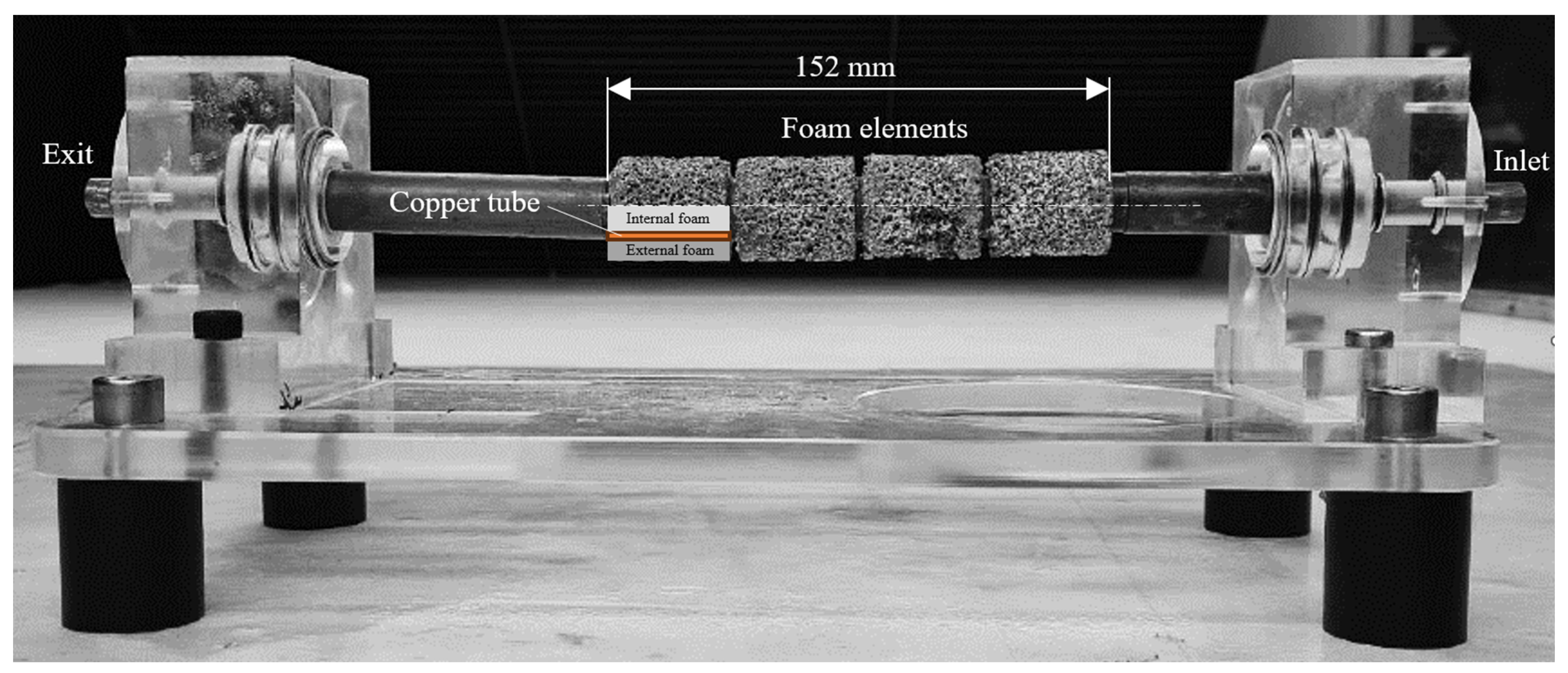
To maximize the thermal energy dispersion potential, four foam elements were stacked as illustrated in Figure 2 below. Reference measurements were conducted with a hollow copper tube that replaced the 152 mm foam element section, as well as the external copper tubes between the acrylic supports, i.e., the overall length of the heat exchanger remained identical.
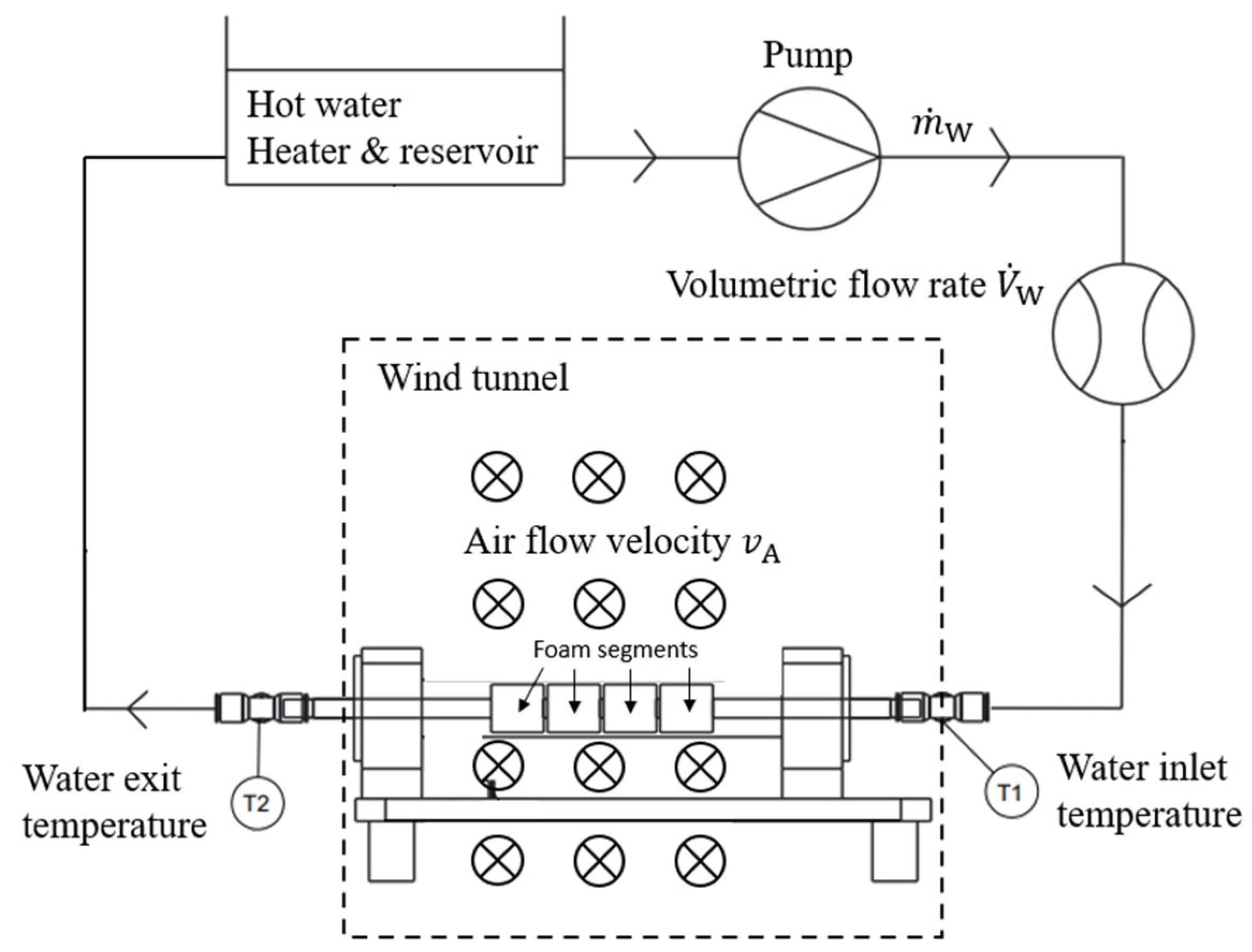
The measurement platform utilized in this study is based on an Armfield HT30XC benchtop service unit, the schematic of which is depicted in Figure 3. Initially, warm water at a near constant temperature ranging between 65.1 °C and 65.4 °C is introduced into the inlet of the heat exchanger unit. Thermocouples positioned at the inlet and outlet of the unit (experimental uncertainty ±   0.1 °C) measure temperatures T 1 and T 2 , respectively. After exiting the copper tube, the water passes through a hot water reservoir for reheating before re-entering the heat exchanger unit. The volumetric flow rate of the water ( V ˙ W ) is regulated by a pump and monitored using a Cynergy3 UF25B ultrasonic flowmeter (experimental uncertainty ±   3 % ). The volumetric flow rate is converted into a mass flow rate m ˙ W utilizing the known density of water at the average temperature T 1 + T 2 2 .
For the experiments involving natural convection, the setup is positioned within a closed room to ensure the absence of external airflow. Conversely, for forced convection tests, the setup is placed centrally within a circulating wind tunnel featuring a cross-sectional area of 0.5 m by 0.5 m and a measurement section length of 2.6 m. The airflow is directed towards the heat exchanger from its side, with a velocity denoted as v A . It should be noted that this velocity corresponds to the free air flow inside the wind tunnel. The local air flow velocity within the external aluminium foam will vary. The hot water reservoir, pump, volumetric flow meter, and tubing are located outside the wind tunnel, whereas the heat exchanger unit is placed at the halfway point (1.3 m) of the wind tunnel’s measurement section. Air velocity is controlled by adjusting the RPM of a large fan that drives the airflow. A precision anemometer was employed for accurate calibration of the air flow velocity (experimental uncertainty ±   4 % ). In all cases, the ambient air temperature was kept approximately constant (between 18.2 °C and 20.1 °C).
A thermodynamic analysis of the internal copper tube volume reveals the energy change rate ( d E / d t ) as the sum of the rates of heat transfer ( Q ˙ ), power ( W ˙ ), and the mass flow rate of water ( m ˙ W ), multiplied by the specific enthalpy difference between inlet and outlet conditions, further accounting for gravitational potential and kinetic energies:
d E d t = Q ˙ W ˙ + m ˙ W h 1 h 2 + 1 2 v 1 2 v 2 2 + g · z 1 z 2
For a steady-state operation ( d E / d t = 0 ), horizontal orientation ( z 1 = z 2 ), and neglecting changes in kinetic energy ( v 1 v 2 ), this equation simplifies to determine the heat transfer from the internal mass stream ( Q ˙ ):
Q ˙ = m ˙ W h 2 h 1
Considering the experimental uncertainties in mass flow rate and temperature, and assuming a constant heat capacity of water within the relevant temperature range, the overall uncertainty for the rate of transfer is approximately 3.2%.
The heat transfer mechanisms encompass conduction, convection, and radiation. Given the relatively low temperatures, radiative heat transfer is deemed negligible. Similarly, stray heat transfer through the acrylic supports of the heat exchanger assembly is deemed minimal; thus, most of the heat transfer occurs toward the surrounding air via convection. Enthalpy values are determined using saturated liquid (SL) data at corresponding inlet and exit temperatures, approximating the specific enthalpy ( h i ) to that of saturated liquid ( h S L ( T i ) .).
In an ideal scenario, the heat exchanger effectively decreases the temperature of the heated water stream to match that of the ambient air T A . This optimal condition yields the maximum achievable rate of heat transfer Q ˙ m a x . Utilizing this maximum rate, an ideal efficiency term for the heat exchanger can be defined as follows:
ε = Q ˙ Q ˙ m a x = m ˙ W h 2 h 1 m ˙ W h m i n h 1   = h S L T 2 h S L ( T 1 ) h S L T A h S L ( T 1 )

3. Results and Discussion

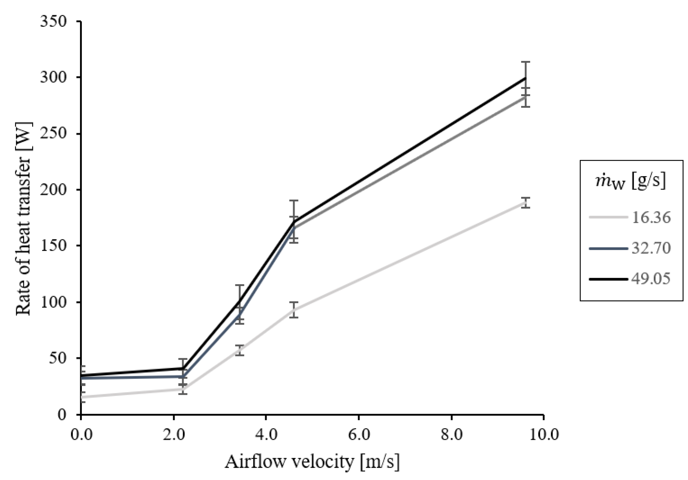
Figure 4 illustrates the results of the reference measurements conducted on a single hollow copper tube exposed to various air flow velocities. The dimensions of this copper tube (with an outer diameter of 19 mm and a wall thickness of 0.9 mm) are identical to the copper tube embedded within the aluminium foam elements. Each test was repeated at least five times, with the error bars representing the standard deviation of measurements. The three coloured lines depict different mass flow rates of water m ˙ W passing through the interior of the copper tube.
Plotting the rate of heat transfer, Q ˙ , against the airflow velocity, v A , reveals a clear trend. Notably, the lowest heat transfer occurs under natural convection conditions (i.e., v A = 0 m/s), ranging from 16.7 W ( m ˙ W = 16.36 g/s) to 34.7 W ( m ˙ W = 49.05 g/s). At v A = 2.0 m/s, only a modest increase in heat transfer is observed relative to natural convection; however, heat transfer increases rapidly for higher values of v A . Another trend emerges as overall heat transfer increases with the mass flow rate of water, m ˙ W . This increase is particularly pronounced between 16.36 g/s and 32.70 g/s. The subsequent increment to 49.05 g/s yields comparatively marginal increases in Q ˙ . This can be attributed to the predominant restriction of overall heat transfer by convective heat transfer from the outer copper tube to the surrounding air. Thus, the augmentation of airflow velocity exerts a more substantial influence on overall heat transfer performance compared to a further increase in m ˙ W .
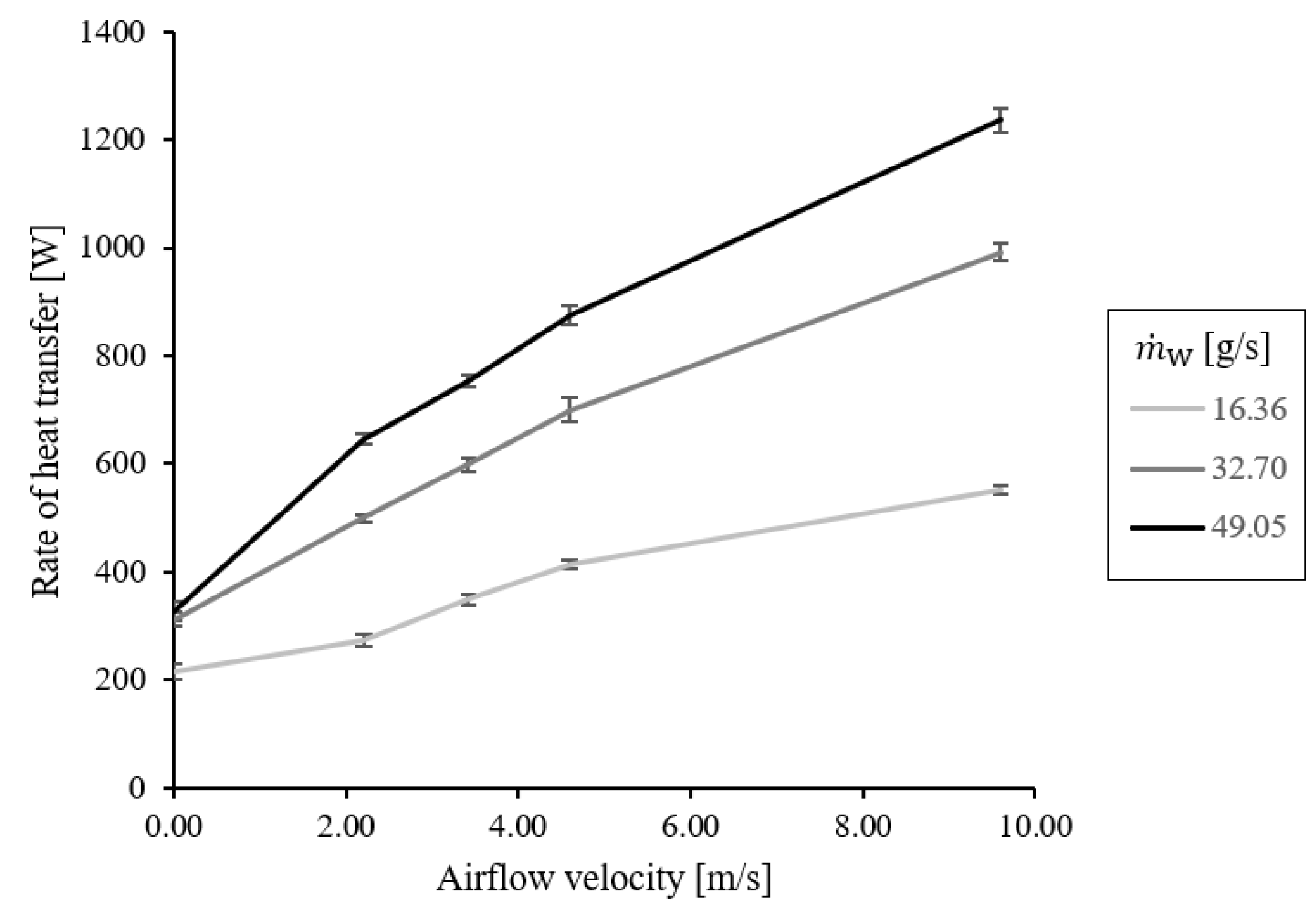
Figure 5 presents the corresponding data obtained from measurements utilizing aluminium-foam heat exchanger elements. In comparison to Figure 4, notably higher rates of heat transfer, Q ˙ , are observed, indicating a distinct performance enhancement. Under natural convection conditions, the average values range from 215 W ( m ˙ W = 16.36 g/s) to 326 W ( m ˙ W = 49.05 g/s), showcasing a distinct increase of 1270% and 840% compared to the single copper tube, respectively. Similar to the copper tube, heat transfer intensifies with increasing airflow velocity. Additionally, heat transfer increases with the mass flow rate of the water traversing through the embedded tube. However, unlike the copper tube, a notable deviation is evident for mass flow rates m ˙ W = 32.70 g/s and m ˙ W = 49.05 g/s. This observation suggests that due to the exterior aluminium foam, overall heat transfer experiences lesser restriction by convective heat transfer to the ambient air in comparison to the copper tube.
An analysis of Reynolds number suggests that the air flow is not laminar under convective conditions (natural convection not considered here). At the lowest air flow (2.2 m/s) the Reynolds number was calculated at 2801 for the copper pipe and 4481 for the external diameter of the foam (32 mm). At the highest air flow (10 m/s), these values increase to 12,222 and 19,555, respectively. This suggests that the air flow conditions around the bare copper pipe begin under conditions that are typically considered as unstable transition flow at the lowest flow setting and quickly become turbulent. It must be stated that the outer aluminium foam is likely to have some air flow permeating the structure, enhancing the heat transfer surface area. In practice, this complicates a Reynolds number analysis because the effective hydraulic diameter is reduced, and the air velocity will change depending on foam depth (potentially becoming laminar at some points).
On the water side, the lowest flow setting produces Reynolds numbers of 1265 and 1558 for the copper pipe and aluminium foam, respectively, suggesting that both have laminar flow conditions. Increasing water flow from 16 to 32 g/s increases the Reynolds number to 2529 and 3116, respectively. These flow conditions are considered unstable and transitioning towards more turbulent flow. At the highest water flow setting (49 g/s), the Reynolds numbers are 3793 and 4673, respectively, indicating that fully developed turbulent flow conditions have not yet been reached. Here it is noted that Reynolds number is defined as follows (4):
R e = ρ v d μ
where ρ is the density of the water, v is the superficial velocity of the water, d is the diameter of the copper tube (15 mm) and μ is the viscosity of the water. The velocity term was based on the volumetric flow rate and cross-sectional area of the pipe. In the case of the aluminium foam, the velocity is based on Equation (5):
v A l   f o a m = U ε
where vAl foam is the velocity through the foam pore space (based on the empty pipe velocity corrected by foam porosity.
The reason for the increased Re values for the aluminium foam is mainly due to the reduced cross-sectional area for flow. In reality, the water flows through the inner foam structure in a series of interconnecting channels, from one connected pore to another.
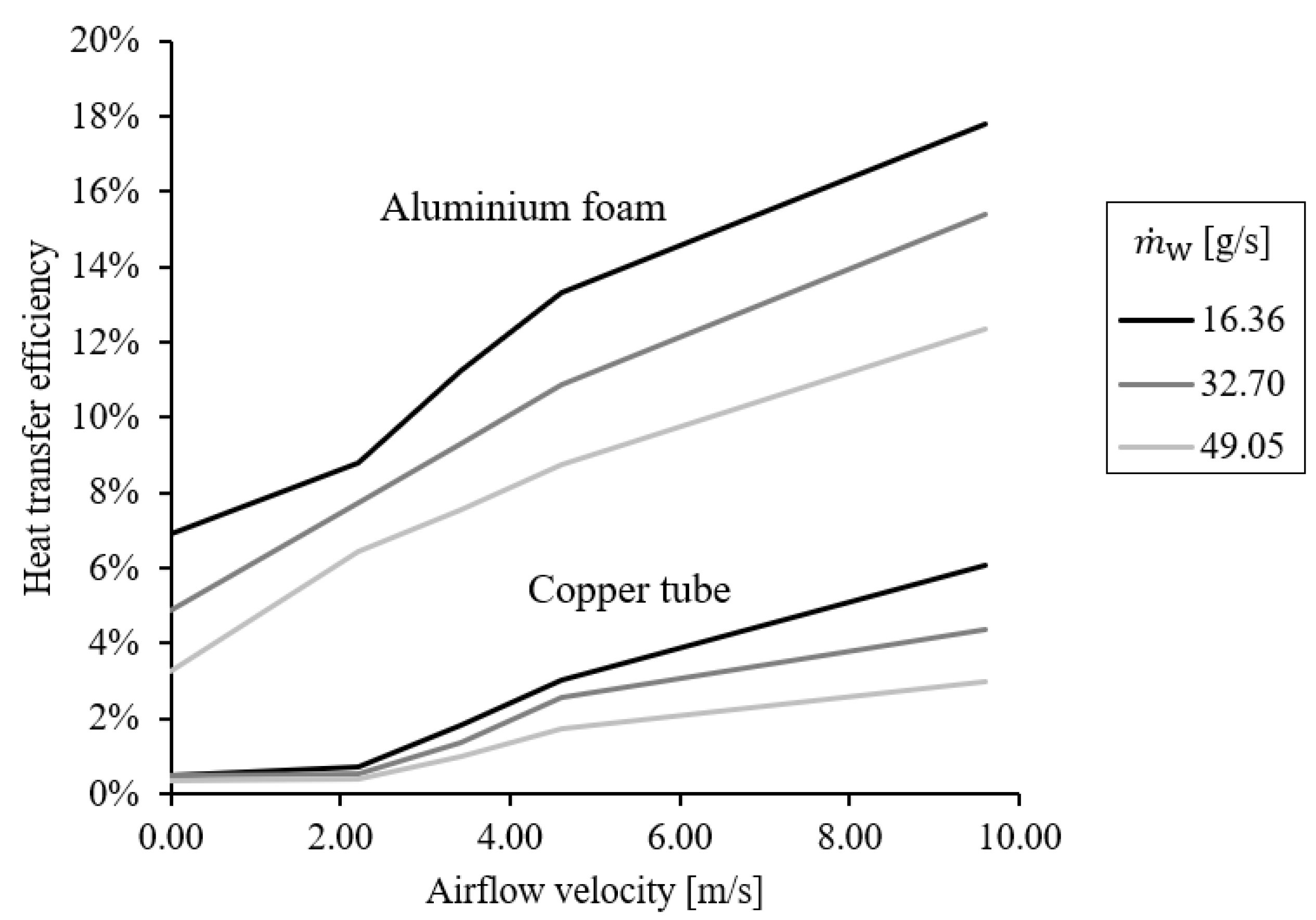
Figure 6 illustrates the heat exchanger efficiencies calculated using Equation (3). It contains two distinct groups of curves: one for the copper tube (with lower efficiencies) and another for the aluminium foam (with higher efficiencies). The highest efficiency achieved (17.8%) corresponds to aluminium foam at the maximum airflow velocity and minimum water mass flow rate.
In general, efficiencies are relatively low due to the exit temperature of the cooling water exceeding the ambient temperature. However, the integration of aluminium foam significantly enhances heat transfer efficiency compared to using a single copper tube. Furthermore, efficiency demonstrates a positive correlation with airflow rate, due to the improved convective heat transfer between the copper tube/aluminium foam surface and the surrounding air. Interestingly, efficiency also improves with the lower mass flow rates of warm water passing through the copper tube. This finding suggests that overall heat transfer is primarily limited by convective heat transfer to the surrounding air, as elaborated further below.
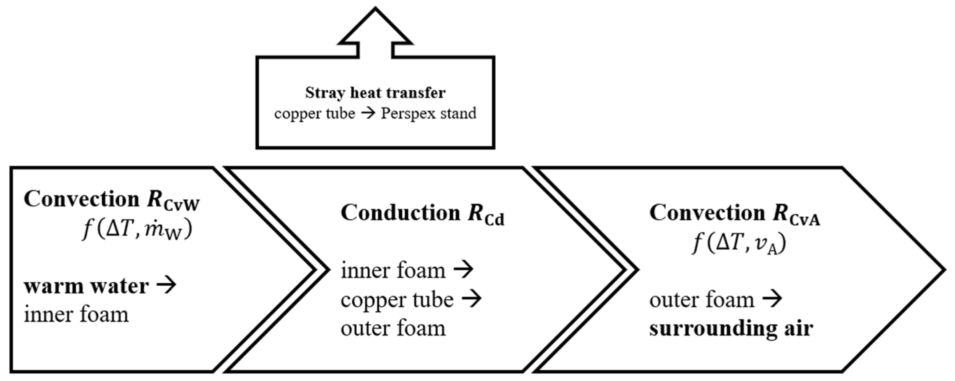
A thermal resistance model of the experiment is depicted in Figure 7. Thermal energy transfers from the heated water to the surface of the aluminium foam inside the tube via convection. This process benefits from the relatively high volumetric surface area of the foam. Conversely, in the reference tests with a single copper tube, only the comparatively smaller internal surface area of the copper tube is available for convective heat transfer. This convective heat transfer is limited by the convective resistance R C v W . Subsequently, thermal energy conducts from the inner foam through the copper tube wall to the outer foam. The resulting conductive resistance R C d is minimized by employing materials with high thermal conductivities (i.e., aluminium and copper) and reducing thermal contact resistances. Finally, thermal energy dissipates to the ambient air via the large volumetric surface area of the outer foam, quantified by the convective resistance R C v A . Stray heat transfer via conduction through the acrylic stands and polymer piping is considered negligible for all tests.
The convective resistance, R C v W , is governed by the internal foam geometry, the temperature difference, Δ T , between water and aluminium foam, and the mass flow rate of the water, m ˙ W . In this experiment, the foam geometry, water inlet temperature, and ambient temperature remain approximately constant. Hence, the mass flow rate m ˙ W serves as the only free variable. Figure 4 and Figure 5 clearly demonstrate that overall heat transfer increases for higher mass flow rates, indicating a decrease in the convective resistance R C v W . However, in the case of the copper tube, only a marginal increase in overall heat transfer is observed when transitioning from the medium to the highest mass flow rate m ˙ W . In this case, the overall heat transfer Q ˙ does not seem limited by the convective heat transfer resistance R C v W , and hence a further increase in the mass flow rate has a diminishing impact.
The conductive thermal resistance, R C d , is constant throughout all measurements. Due to the high thermal conductivity of copper and aluminium, this resistance is considered small compared to the convective ones.
The second convective resistance R C v A is contingent on the temperature difference between the outer foam surface and the ambient air temperature Δ T , as well as the airflow velocity v A . Analogous to R C v W , the overall temperature gradient is approximately identical in all measurements. Thus, the airflow velocity v A serves as the free variable. Figure 3 and Figure 4 clearly indicate that overall heat transfer increases with v A . Minimum values are attained for natural convection ( v A = 0), while maximum values emerge at the highest considered velocity v A = 9.6 m/s. Notably, whilst still increasing, the gradients of the curves diminish for higher airflow velocities. This observation can be attributed to the exit temperature of the water decreasing slightly, consequently reducing the temperature difference driving convective heat transfer to the ambient air. Another explanation is that overall heat transfer is constrained by all thermal resistances simultaneously, and for higher airflow velocities, the internal convective resistance R C v W gradually becomes the key limiting factor.
In summary, it is crucial to operate the heat exchanger in a way that minimizes the overall thermal resistance R t o t = R C v W + R C d + R C v A . Therefore, increasing the water mass flow rate to reduce R C v W will yield diminishing improvements if the airflow velocity is low and thus R C v W remains high.
In our prior investigation [10], a similar heat exchanger setup featuring identical aluminium foam elements underwent testing with the outer foam immersed in a cold-water stream, m ˙ C W , as opposed to ambient air. A comparison of the observed heat transfer rates is detailed in Table 2 below, highlighted in the grey cells. Regardless of the secondary heat-transfer fluid, overall heat transfer increases with higher mass flow rates of the warm water, m ˙ W . However, markedly higher values are recorded for external water cooling, in contrast to air cooling. Even at the highest considered air flow velocity, v A = 9.6 m/s, the heat transfer only achieves 17.7% to 20.3% of the values attained for water cooling at the lowest external mass flow rate of m ˙ C W = 16.4 g/s. Nevertheless, for applications with lower cooling loads, air-cooled metal foam heat exchangers emerge as a cost-effective alternative with substantially reduced complexity.

4. Conclusions

This study investigated the heat transfer performance of air-cooled metal foam heat exchangers through experimental measurements. By employing counter-gravity infiltration casting, aluminium foam elements were manufactured to embed a copper tube for internal mass flow containment. The experiments, conducted under both natural and forced convection conditions, showcased significantly enhanced heat transfer performance with aluminium foam compared to a single copper tube.
The results revealed a clear correlation between heat transfer performance, airflow velocity, and water mass flow rate. Under natural convection conditions, the aluminium foam-heat exchanger demonstrated a distinct increase in heat transfer rates, outperforming the copper tube by up to 1270% and 840% for varying water mass flow rates. Similarly, under forced convection, the aluminium-foam heat exchanger exhibited superior heat transfer capabilities compared to the copper tube. Efficiency analysis further highlighted the effectiveness of aluminium-foam heat exchangers, showcasing higher efficiencies compared to copper tube configurations. Thermal resistance modelling elucidated the underlying heat transfer mechanisms, emphasizing the importance of minimizing overall thermal resistance for optimal heat transfer performance.
Overall, this study underscores the promising potential of air-cooled metal foam heat exchangers for various thermal management applications, offering enhanced heat transfer performance.

Author Contributions

Conceptualization, T.F.; methodology, T.F.; software, R.S.; formal analysis, N.M.; investigation, N.M.; writing—original draft, T.F. and R.S.; writing—review and editing, T.F. and N.M.; visualization, R.S. All authors have read and agreed to the published version of the manuscript.

Funding

The authors acknowledge the financial support provided by the School of Engineering, University of Newcastle, through a Final Year Project Grant.

Data Availability Statement

The data presented in this study are available on request from the corresponding author due to privacy.

Acknowledgments

The authors express their gratitude to Mohd Izran Bin Mohd Fadzil for his diligent efforts in conducting experimental measurements as part of his Final Year Honours Project at the University of Newcastle. Additionally, the authors acknowledge the financial support provided by the School of Engineering, the University of Newcastle, through a Final Year Project Grant. Finally, the authors extend their appreciation to the dedicated team of the engineering workshop at the University of Newcastle for their exceptional technical assistance and support.

Conflicts of Interest

The authors declare no conflict of interest.

References

  1. Lu, W.; Zhao, C.Y.; Tassou, S.A. Thermal analysis on metal-foam filled heat exchangers. Part I: Metal-foam filled pipes. Int. J. Heat Mass Transf. 2006, 49, 2751–2761. [Google Scholar] [CrossRef]
  2. Chandora, N.; Mani, A.; Advaith, S. Investigation of heat transfer and pressure drop characteristics in metal-foam filled channels in a plate heat exchanger: A comparative experimental study. Appl. Therm. Eng. 2024, 241, 122368. [Google Scholar] [CrossRef]
  3. Feng, S.; Kuang, J.; Wen, T.; Lu, T.; Ichimiya, K. An experimental and numerical study of finned metal foam heat sinks under impinging air jet cooling. Int. J. Heat Mass Transf. 2014, 77, 1063–1074. [Google Scholar] [CrossRef]
  4. Morkos, B.; Dochibhatla, S.V.S.; Summers, J.D. Effects of Metal Foam Porosity, Pore Size, and Ligament Geometry on Fluid Flow. J. Thermal Sci. Eng. Appl. 2018, 10, 041007. [Google Scholar] [CrossRef]
  5. Chumpia, A.; Hooman, K. Performance evaluation of single tubular aluminium foam heat exchangers. Appl. Therm. Eng. 2014, 66, 266–273. [Google Scholar] [CrossRef]
  6. T’joen, C.; De Jaeger, P.; Huisseune, H.; Van Herzeele, S.; Vorst, N.; De Paepe, M. Thermo-hydraulic study of a single row heat exchanger consisting of metal foam covered round tubes. Int. J. Heat Mass Transf. 2010, 53, 3262–3274. [Google Scholar] [CrossRef]
  7. Ambrosio, G.; Bianco, N.; Chiu, W.K.; Iasiello, M.; Naso, V.; Oliviero, M. The effect of open-cell metal foams strut shape on convection heat transfer and pressure drop. Appl. Therm. Eng. 2016, 103, 333–343. [Google Scholar] [CrossRef]
  8. Li, Y.; Wang, S.; Zhao, Y. Experimental study on heat transfer enhancement of gas tube partially filled with metal foam. Exp. Therm. Fluid Sci. 2018, 97, 408–416. [Google Scholar] [CrossRef]
  9. Fiedler, T.; Moore, R.; Movahedi, N. Manufacturing and Characterization of Tube-Filled ZA27 Metal Foam Heat Exchangers. Metals 2021, 11, 1277. [Google Scholar] [CrossRef]
  10. Fiedler, T.; Movahedi, N. Compact Aluminium Foam Heat Exchangers. Metals 2023, 13, 1440. [Google Scholar] [CrossRef]
  11. Li, Y.; Niu, Z.; Gao, X.; Guo, J.; Yang, X.; He, Y.-L. Effect of filling height of metal foam on improving energy storage for a thermal storage tank. Appl. Therm. Eng. 2023, 229, 120584. [Google Scholar] [CrossRef]
  12. Lv, C.; Li, W.; Du, J.; Liang, J.; Yang, H.; Zhu, Y.; Ma, B. Experimental investigation of permeability and Darcy-Forchheimer flow transition in metal foam with high pore density. Exp. Therm. Fluid Sci. 2024, 154, 111149. [Google Scholar] [CrossRef]
  13. Zhang, Z.; Yan, G.; Sun, M.; Li, S.; Zhang, X.; Song, Y.; Liu, Y. Forced convective heat transfer performance of foam-like structures—Comparison of the Weaire-Phelan and the Kelvin structures with real metal foam. Int. J. Heat Mass Transf. 2024, 227, 125558. [Google Scholar] [CrossRef]
  14. Konduru, R.N.; Farges, O.; Schick, V.; Hairy, P.; Gaillard, Y.; Parent, G. Experimental and numerical investigation of porous heat exchangers with Kelvin cell structured foam at high temperatures: Coupled conduction-convection and radiation heat transfer. Int. J. Heat Mass Transf. 2024, 224, 125253. [Google Scholar] [CrossRef]
Figure 1. Micro-CT images of aluminium foam sample #3: (a) reconstructed 3D outer surface image and (b) bisected 3D section showing internal structure.
Metals 14 00750 g001
Figure 2. Heat exchanger unit with aluminium foam elements.
Metals 14 00750 g002
Figure 3. Schematics of the experimental setup.
Metals 14 00750 g003
Figure 4. Rates of heat transfer for an air-cooled copper tube without aluminium foam.
Metals 14 00750 g004
Figure 5. Rates of heat transfer for an air-cooled aluminium-foam heat exchanger.
Metals 14 00750 g005
Figure 6. Heat exchanger efficiencies.
Metals 14 00750 g006
Figure 7. Thermal resistance model (adapted from [10]).
Metals 14 00750 g007
Table 1. Sample characteristics determined from micro-CT analysis.
Sample CharacteristicsAverage#1#2#3#4
Volume [mL]29.327.829.730.828.9
Surface area/volume [μm2/μm3]
-
Exterior foam
0.001660.001750.001540.001600.00175
-
Interior foam
0.003910.003970.003700.003810.00416
Surface area enhancement [%]
(relative to cylindrical pipe)
-
Exterior foam
12571285120412141326
-
Interior foam
19551985184919062080
Porosity, [vol.%]
-
Exterior foam
80.080.879.678.980.6
-
Interior foam
65.962.968.765.066.9
Average pore size [μm]
-
Exterior foam
19241757202820311879
-
Interior foam
20841874238619962079
Table 2. Rates of heat transfer Q ˙ (grey areas [W]) for water and air as the secondary heat exchange fluid.
Values Retrieved from [10]This Study
m ˙ C W [g/s]Mass Flow Rate of the Outer Water Stream [g/s] v A [m/s]
16.432.749.09.6
16.4106412871403188
32.7129716561760282
49.0147117271789299
Disclaimer/Publisher’s Note: The statements, opinions and data contained in all publications are solely those of the individual author(s) and contributor(s) and not of MDPI and/or the editor(s). MDPI and/or the editor(s) disclaim responsibility for any injury to people or property resulting from any ideas, methods, instructions or products referred to in the content.