
A New Wear Calculation Method for Galvanized Ultra-High-Strength Steel during Hot Stamping

Abstract
:1. Introduction
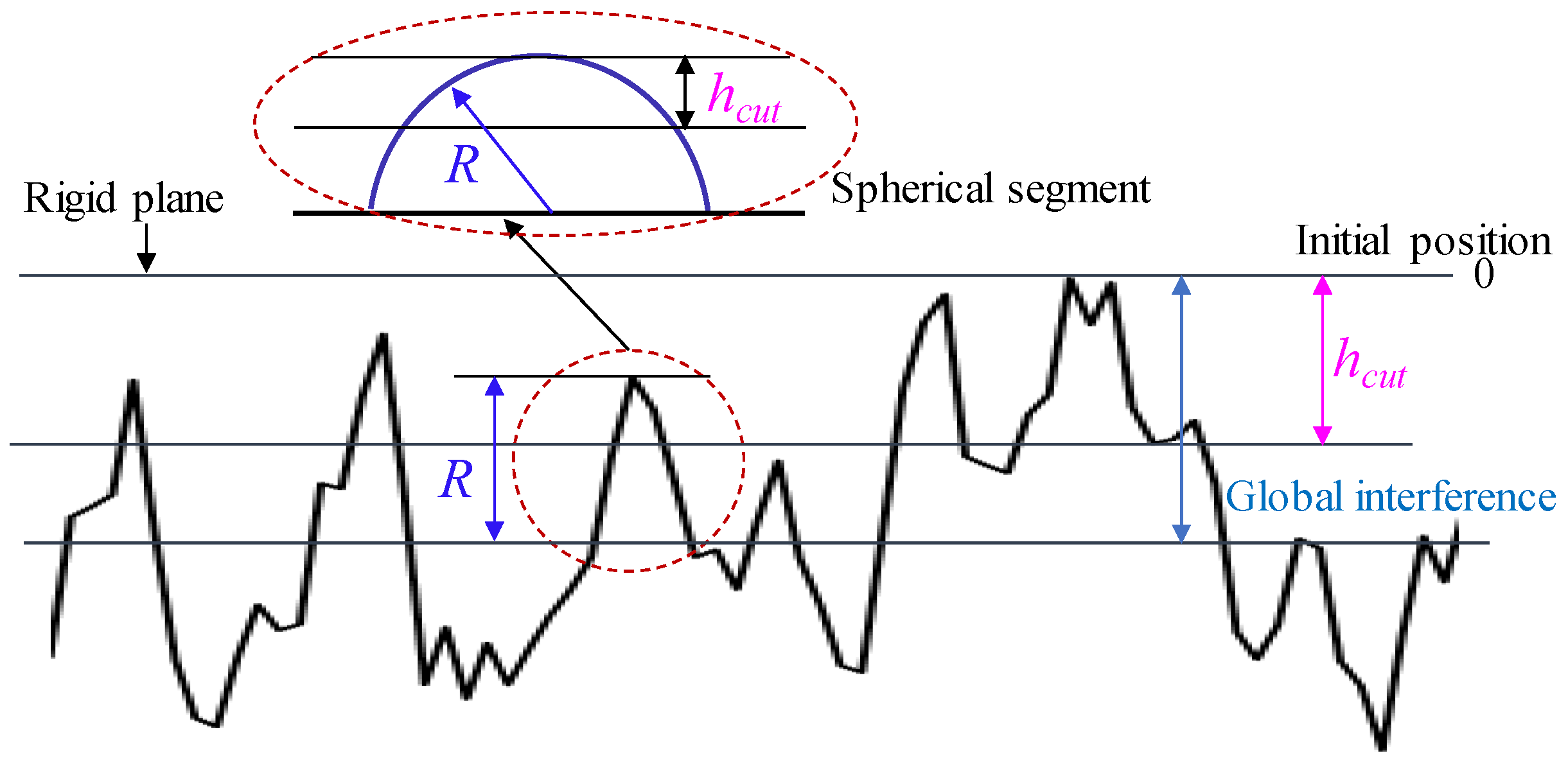
2. Contact Analysis
- (1)
- In accordance with the principle of energy conservation, it is understood that the total internal energy of the sheet metal during the compression phase is equivalent to the external work exerted upon it. This relationship is encapsulated in Equation (1) as follows:where (Nmm) is the external work conducted during the compression of the sheet metal, (Nmm) is the energy absorbed by the plastic deformation of the micro-asperities on the surface of the galvanized layer, and (Nmm) is the energy required for shear during the relative motion of the micro-asperities on the galvanized layer surface.
- (2)
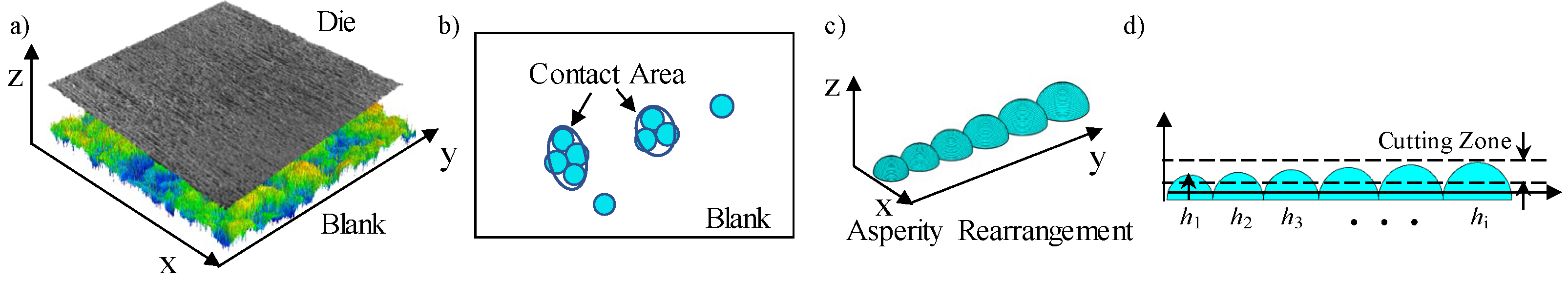
- During the contact process of the sheet metal, the total normal force is constituted by the following two components: the aggregate normal forces exerted by the contact micro-asperities and the shearing force that arises between the contacting and non-contacting micro-asperities. This comprehensive force relationship is articulated in Equation (2).where (N) is the total normal force, (N) is the normal force of the galvanized contact micro-asperities, and (N) is the shearing force between the contacting and non-contacting micro-asperities.
- (3)
- Together, the galvanized layer and the substrate must adhere to the principle of volume conservation throughout the contact phase. This stipulation ensures that the combined volume of these two components remains invariant during the interaction.where is the volume of compressed sheet metal, is the volume of the compressed galvanized layer, and is the volume of compressed sheet metal substrate.
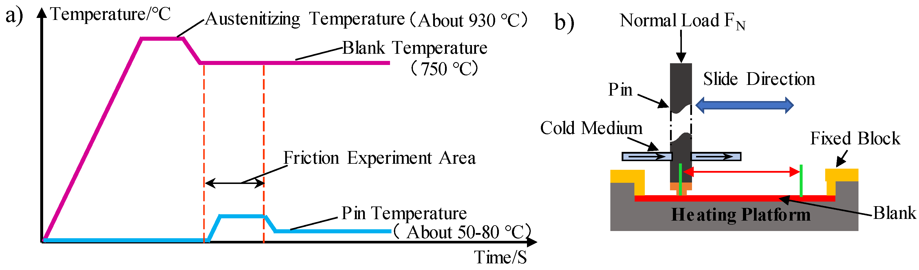
3. Experiments
3.1. Parameters and Procedures
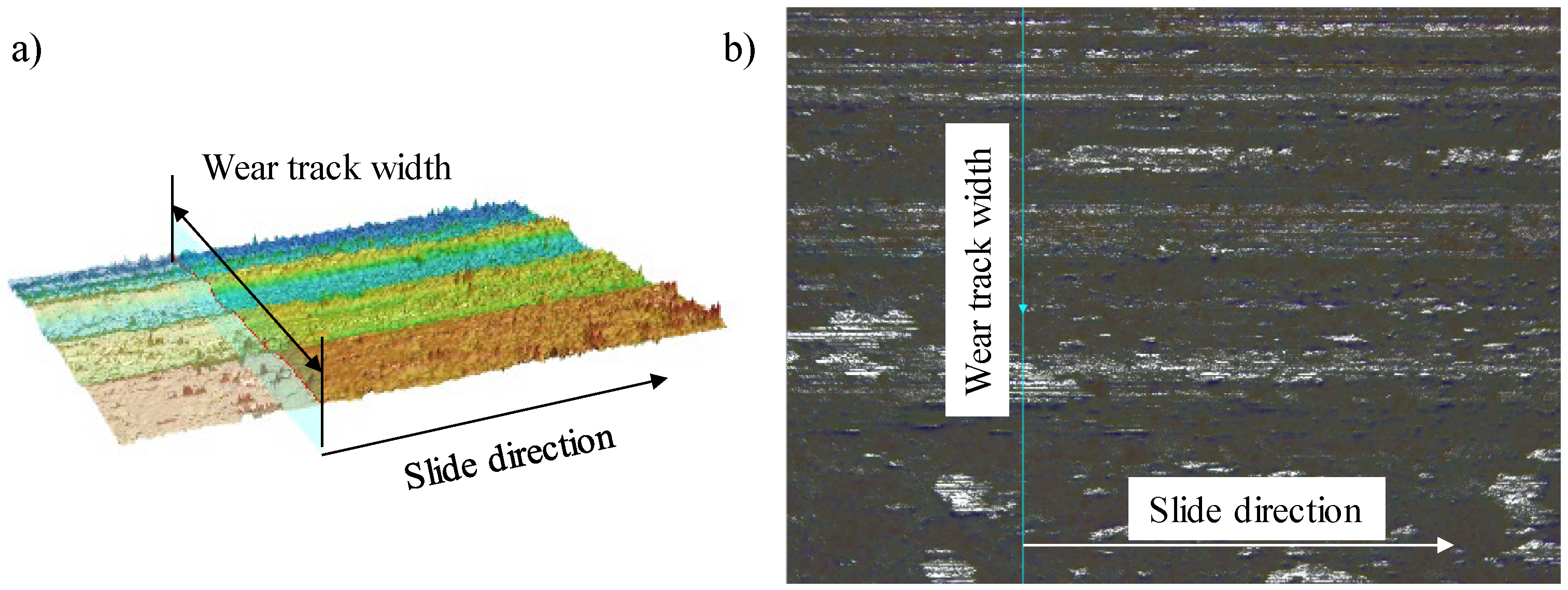
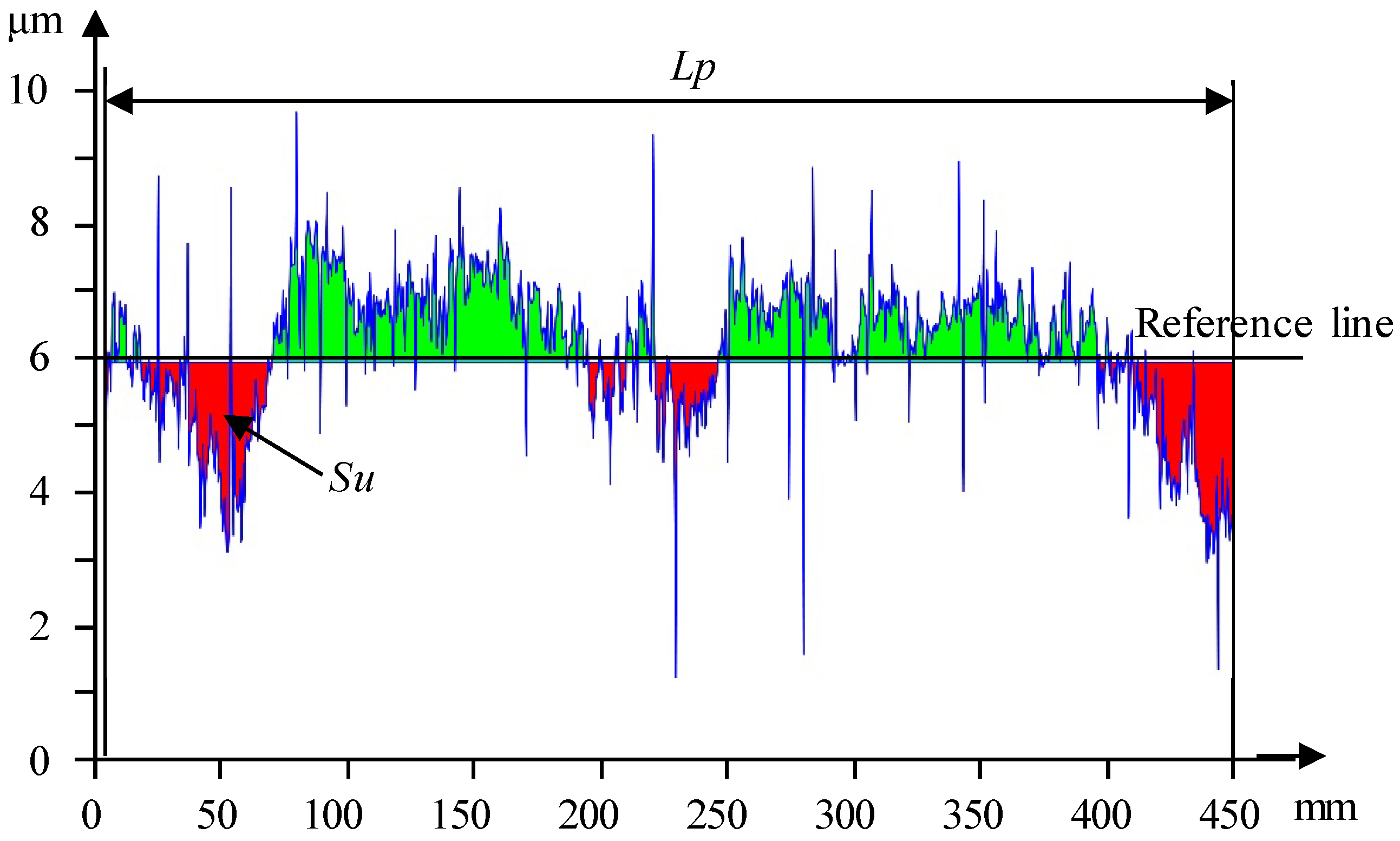
3.2. Wear Amount Analysis
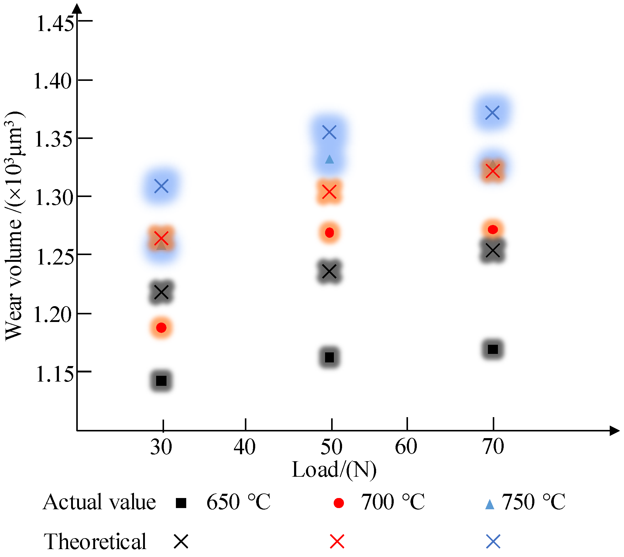
4. Results and Discussion
5. Conclusions
Author Contributions
Funding
Data Availability Statement
Conflicts of Interest
References
- Singh, J.; Khan, M.S.; Oliveira, J.P.; Arora, K.S. Brazing of high-strength steels: Recent developments and challenges. J. Manuf. Process. 2024, 115, 289–309. [Google Scholar] [CrossRef]
- Li, J.; Tong, C.; Zhang, R.; Shi, Z.; Lin, J. A data-informed review of scientific and technological developments and future trends in hot stamping. Int. J. Lightweight Mater. Manuf. 2024, 7, 327–343. [Google Scholar] [CrossRef]
- Bruschi, S.; Ghiotti, A.; Simonetto, E. 3.08—Hot stamping of high strength-to-weight metal alloys. In Comprehensive Materials Processing, 2nd ed.; Hashmi, S., Ed.; Elsevier: Oxford, UK, 2024; pp. 181–208. [Google Scholar]
- Güler, H.; Ertan, R.; Özcan, R. Investigation of the hot ductility of a high-strength boron steel. Mater. Sci. Eng. A 2014, 608, 90–94. [Google Scholar] [CrossRef]
- Zhang, Y.; Qin, Y.; Chen, T.; Ji, C. Improvement of microstructure and mechanical properties of laser welded Al-Si coated 22MnB5 steel joints by austenitic element copper. Mater. Today Commun. 2024, 39, 108989. [Google Scholar] [CrossRef]
- Guo, N.; Zhang, X.; Hou, Z.; Wang, W.; Yang, D.; Min, J.; Ming, P.; Zhang, C. Hot stamping of ultra-thin stainless steel sheets for bipolar plates. J. Mater. Process. Technol. 2023, 317, 117987. [Google Scholar] [CrossRef]
- Chantzis, D.; Tracy, M.; Liu, H.; Politis, D.J.; Fu, M.W.; Wang, L. Design optimization of hot stamping tooling produced by additive manufacturing. Addit. Manuf. 2023, 74, 103728. [Google Scholar] [CrossRef]
- Hirtler, M.; Ünsal, I.; Buhl, J.; Bambach, M. Investigation of quench hardening behavior of directed energy deposited 22MnB5 steel for local reinforcement of hot stamping parts. CIRP J. Manuf. Sci. Technol. 2022, 39, 223–231. [Google Scholar] [CrossRef]
- Wiklund, D.; Wihlborg, A.; Rosén, B.-G. Evaluation of surface topography parameters for friction prediction in stamping. Wear 2004, 257, 1296–1300. [Google Scholar] [CrossRef]
- Billur, E. Hot stamping of ultra high-strength steels. In From a Technological and Business Perspective; Springer: Cham, Switzerland, 2019. [Google Scholar]
- Ghiotti, A.; Bruschi, S.; Sgarabotto, F.; Bariani, P. Tribological performances of Zn-based coating in direct hot stamping. Tribol. Int. 2014, 78, 142–151. [Google Scholar] [CrossRef]
- Ghiotti, A.; Bruschi, S.; Medea, F. Comparison of tribological and wear performances of AlSi and Zn coatings in hot stamping of boron steel sheets. Wear 2015, 332, 810–821. [Google Scholar] [CrossRef]
- Hardell, J.; Prakash, B. High-temperature friction and wear behaviour of different tool steels during sliding against Al-Si-coated high-strength steel. Tribol. Int. 2008, 41, 663–671. [Google Scholar] [CrossRef]
- Pelcastre, L.; Hardell, J.; Prakash, B. Tribological behaviour of Zn coated UHSS sliding against hot-work tool steel at high temperatures. Wear 2017, 376, 423–432. [Google Scholar] [CrossRef]
- Kondratiuk, J.; Kuhn, P. Tribological investigation on friction and wear behaviour of coatings for hot sheet metal forming. Wear 2011, 270, 839–849. [Google Scholar] [CrossRef]
- Schwingenschlögl, P.; Merklein, M. Characterization of tribological conditions within direct hot stamping. J. Mater. Process. Technol. 2020, 278, 116535. [Google Scholar] [CrossRef]
- Wang, W.; Wang, K.; Zhao, Y.; Hua, M.; Wei, X. A study on galling initiation in friction coupling stretch bending with advanced high strength hot-dip galvanized sheet. Wear 2015, 328–329, 286–294. [Google Scholar] [CrossRef]
- Zhou, L.; Gao, K.; Zheng, X.; Wang, W.; Wei, X.; Hua, M. Developing of galling during the forming and its improvement by physical vapour depositing. Surf. Eng. 2017, 34, 493–503. [Google Scholar] [CrossRef]
- Gao, H.; Zhao, L.; Li, L.; Wu, S.; Lin, Z.; Wang, Q. Effect of Wear-Induced Surface Deformation on Stick-Slip Friction of Galvanized Automotive Steels. Langmuir ACS J. Surf. Colloids 2022, 38, 11459–11467. [Google Scholar] [CrossRef] [PubMed]
- Zhuang, W.; Xie, D.; Chen, Y. Experimental investigation of the effect of the material damage induced in sheet metal forming process on the service performance of 22MnB5 steel. Chin. J. Mech. Eng. 2016, 29, 747–755. [Google Scholar] [CrossRef]
- Zhuang, W.; Wang, P.; Xie, D.; Shi, H. Experimental study and a damage model approach to determine the effect of hot forming deformation on the service performance of 22MnB5 steel. J. Manuf. Process. 2019, 47, 10–21. [Google Scholar] [CrossRef]
- Venema, J.; Matthews, D.T.A.; Hazrati, J.; Wörmann, J.; van den Boogaard, A.H. Friction and wear mechanisms during hot stamping of AlSi coated press hardening steel. Wear 2017, 380, 137–145. [Google Scholar] [CrossRef]
- Yu, Z.Q.; Hou, Y.K.; Li, S.H.; Lin, Z.Q.; Zhang, W.G. Surface damage behavior of galvanized steel sheets in forming process under tension-bending. Int. J. Mod. Phys. B 2010, 24, 5877–5884. [Google Scholar] [CrossRef]
- Archard, J.F.; Hirst, W. The wear of metals under unlubricated conditions. Proc. R. Soc. London. Ser. A. Math. Phys. Sci. 1956, 236, 397–410. [Google Scholar]
- Hol, J.; Alfaro, M.; Rooij, M.; Meinders, T.; Felder, E.; Montmitonnet, P. Multiscale friction modeling for sheet metal forming. In Proceedings of the 4th International Conference on Tribology in Manufacturing Processes, ICTMP 2010, Nice, France, 13–15 June 2010. [Google Scholar]
- Shisode, M.; Hazrati, J.; Mishra, T.; De Rooij, M.; Ton, V.D.B. Multi-Scale Contact Modeling of Coated Steels for Sheet Metal Forming Applications. Key Eng. Mater. 2018, 767, 223–231. [Google Scholar] [CrossRef]
- Venema, J. Tribological Interactions and Modelling of Friction in Hot Stamping. Ph.D. Thesis, University of Twente, Enschede, The Netherlands, 2019. [Google Scholar]
- Abspoel, M.; Neelis, B.M.; van Liempt, P. Constitutive behaviour under hot stamping conditions. J. Mater. Process. Technol. 2016, 228, 34–42. [Google Scholar] [CrossRef]
- Kim, S.I.; Her, J.U.; Jang, Y.C.; Lee, Y. Experimental and finite element analysis for fracture of coating layer of galvannealed steel sheet. Trans. Nonferrous Met. Soc. China 2011, 21, s111–s116. [Google Scholar] [CrossRef]
- Kondratiuk, J.; Kuhn, P.; Labrenz, E.; Bischoff, C. Zinc coatings for hot sheet metal forming: Comparison of phase evolution and microstructure during heat treatment. Surf. Coat. Technol. 2011, 205, 4141–4153. [Google Scholar] [CrossRef]
- Han, K.; Lee, I.; Ohnuma, I.; Okuda, K.; Kainuma, R. Micro-Vickers Hardness of Intermetallic Compounds in the Zn-rich Portion of Zn-Fe Binary System. ISIJ Int. 2018, 58, 1578–1583. [Google Scholar] [CrossRef]
- Han, K.; Ohnuma, I.; Okuda, K.; Kainuma, R. Experimental determination of phase diagram in the Zn-Fe binary system. J. Alloys Compd. 2018, 737, 490–504. [Google Scholar] [CrossRef]
- Marder, A.R. The metallurgy of zinc-coated steel. Prog. Mater. Sci. 2000, 45, 191–271. [Google Scholar] [CrossRef]
- Greenwood, J.A.; Williamson, J.B.P.P. Contact of nominally flat surfaces. Proc. R. Soc. Lond. 1966, 295, 300–319. [Google Scholar]
- Chen, W.; Peng, Y.; Wang, Y.; Cao, P.; Zhu, Y.; Guo, Y. Research on high-temperature friction and wear performances of Stellite 12 laser cladding layer against coated boron steels. Wear 2023, 520–521, 204665. [Google Scholar] [CrossRef]
- Su, X.; Tang, N.Y.; Toguri, J.M. Thermodynamic evaluation of the Fe–Zn system. J. Alloys Compd. 2001, 325, 129–136. [Google Scholar] [CrossRef]
- Roux, S.L.; Boher, C.; Penazzi, L.; Dessain, C.; Tavernier, B. A methodology and new criteria to quantify the adhesive and abrasive wear damage on a die radius using white light profilometry. Tribol. Int. 2012, 52, 40–49. [Google Scholar] [CrossRef]
- Pawlus, P.; Reizer, R. Profilometric measurements of wear scars: A review. Wear 2023, 534–535, 205150. [Google Scholar] [CrossRef]


| Condition | Parameter |
|---|---|
| Blank temperature (°C) | 650, 700, 750 |
| Hardness of pins (HRC) | 50 ± 2 |
| The diameter of the pin (mm) | 3.5 |
| Blank size (mm) | 69 × 20 × 1.4 |
| Sliding speed (mm/s) | 4 |
| Normal Load (N) | 30, 50, 70 |
| Time (s) | 9 |
Disclaimer/Publisher’s Note: The statements, opinions and data contained in all publications are solely those of the individual author(s) and contributor(s) and not of MDPI and/or the editor(s). MDPI and/or the editor(s) disclaim responsibility for any injury to people or property resulting from any ideas, methods, instructions or products referred to in the content. |
© 2024 by the authors. Licensee MDPI, Basel, Switzerland. This article is an open access article distributed under the terms and conditions of the Creative Commons Attribution (CC BY) license (https://creativecommons.org/licenses/by/4.0/).
Share and Cite
Peng, Y.; Chen, W.; Zhou, H. A New Wear Calculation Method for Galvanized Ultra-High-Strength Steel during Hot Stamping. Metals 2024, 14, 756. https://doi.org/10.3390/met14070756
Peng Y, Chen W, Zhou H. A New Wear Calculation Method for Galvanized Ultra-High-Strength Steel during Hot Stamping. Metals. 2024; 14(7):756. https://doi.org/10.3390/met14070756
Chicago/Turabian StylePeng, Yuchun, Wei Chen, and Hongming Zhou. 2024. "A New Wear Calculation Method for Galvanized Ultra-High-Strength Steel during Hot Stamping" Metals 14, no. 7: 756. https://doi.org/10.3390/met14070756