Abstract
With the aim of achieving a sustainable society with green manufacturing, every metal-forming process has been changed to a dry process with the use of limited lubricants via regulation. In parallel, die materials must have sufficient wear resistance to prolong the die life even when forming active metals. A massively nitrogen-supersaturated (MNSed) superalloy was selected as a galling-free die substrate to forge oxygen-free copper wires and bars in dry conditions. A plasma immersion nitriding system was utilized to induce nitrogen supersaturation in CoCrMo, forging dies at 723 K for 21.6 ks with a high nitrogen solute content. Microstructure analyses and microhardness testing proved that the MNSed CoCrMo die had a multilayered structure from the top surface to the depth and that the surface hardness increased up to 1300 HV. Dry, cold forging experiments demonstrated that the oxygen-free copper bar was upset, with a reduction in thickness of 70% in a single stroke under low friction. No fresh copper work debris adhered onto the MNSed CoCrMo die surface. The loading–stroke relationship was used to describe the forging behavior, with low friction and without galling.
1. Introduction
Regarding green metal formation in a sustainable society, any emissions other than the product must be minimized to zero using an advanced manufacturing procedure with the recycling of dust in the factory [1]. The regulation and long die/tool life design in dry metal formation with the use of lubricants is key even when fabricating active metal products, including titanium and copper parts [2].
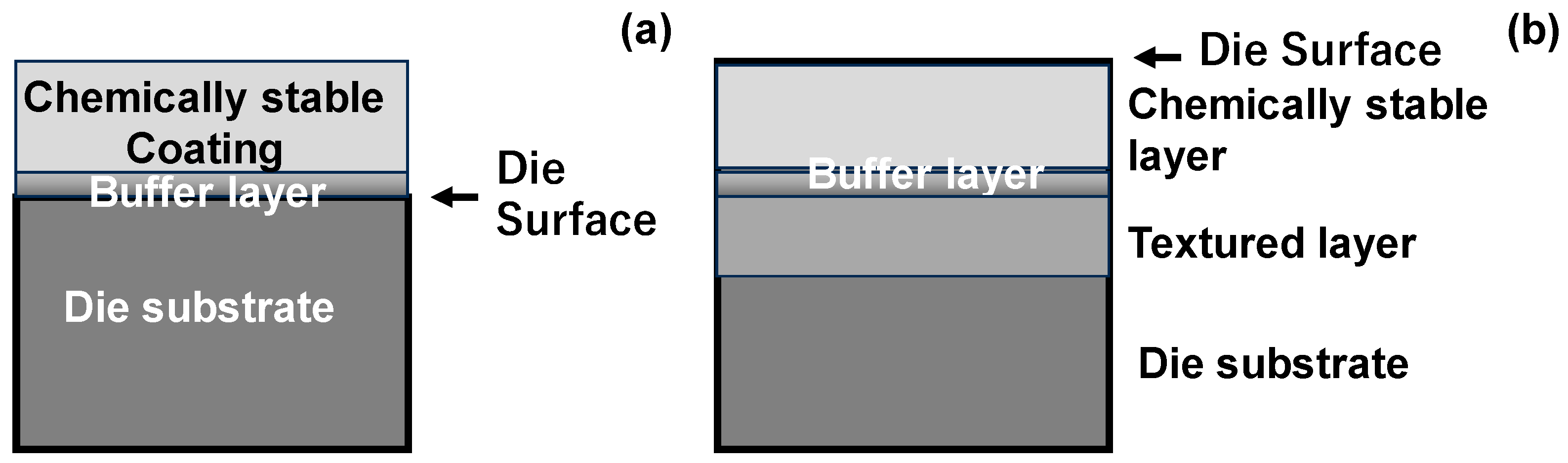
Oxygen-free copper and copper alloys have been widely utilized in electric automotive parts for e-mobility devices [3]. Their ductility and low flow-stress often result in the adhesive wear of machining tools, forging dies, and piercing punches [4]. As explained in [4,5], this galling is induced by various metal-forming parameters such as plastic strain, the surface layer, the lubricating medium, and so forth. In particular, active metals are easy to adhere onto metal-forming dies even in the presence of a protective coating and solid lubricants [4,5,6]. Anti-galling die technology is needed to protect the die surface from severe adhesive wear in the dry forging of those active metals and alloys. As reported in [7,8], diamond and diamond-like carbon (DLC) coatings, with their sufficient hardness and chemical stability, provide a way of being free from galling when dry forging up to a higher reduction in thickness and a larger surface extension. As depicted in Figure 1a, multilayer coatings provide a way of building up the wear-resistant coating system for such a galling-free forging die. In this approach, the total thickness of the deposition layers is often limited to 10 μm, with a risk of adhesive wearing and delamination during the forging operation [9]. In addition, the die material and its mechanical properties make little contribution to the anti-galling forming behavior [10].

Figure 1.
Die material design for galling-free metal forming with the use of a multi-layered microstructure. (a) multi-layers coating onto the die surface by deposition, and (b) multi-layered modification by interstitial atom supersaturation.
A new approach is proposed, as shown in Figure 1b, to build up the multilayered microstructure into the die material. A thick top layer of die materials with a nanograined structure has sufficient hardness, strength, and wear toughness to suppress the adhesion of work-material debris. Through a buffer layer, the textured layer above the original die matrix works to mechanically support the surface layer. A massive nitrogen supersaturation succeeded in the surface modification of the austenitic stainless steel die type AISI316 and martensitic stainless steel die type AISI420 to produce this multilayered microstructure in Figure 1b [11,12]. After plasma immersion nitriding these AISI316 and AISI420 dies at 673 K for 14.4 ks, the MNSed surface layer had a fine nanostructure with a hardness of 1400 HV10N down to a depth of 60 μm without nitride precipitation. In addition, the matrix below this surface layer had a textured microstructure to sustain the compatibility between the surface layer and the original AISI316 and AISI420 matrices. A CoCrMo superalloy was also modified by MNS to produce a multilayered system, as depicted in Figure 1b [13,14]. The MNSed CoCrMo substrate at 673 K had a nanotextured layer with an average nitrogen solute content of 5 mass% and an intensely textured microstructure. The transient layer acted as a buffer layer between this MNSed layer and the CoCrMo matrix.
In the present paper, a mechanically polished CoCrMo die material is prepared and MNSed using a plasma immersion system at 723 K for 21.6 ks to precisely describe the microstructure system of the CoCrMo die surface. XRD (X-ray Diffraction), SEM (Scanning Electron Microscopy)–EDX (Electron Dispersive X-ray spectroscopy), and EBSD (Electron Back-Scattering Diffraction) are utilized for material characterization. The micro hardening test is employed to describe the surface hardness by varying the applied load. The MNSed CoCrMo die is utilized to achieve the dry, cold forging of oxygen-free copper wires without severe galling. A low frictional state is sustained at a high reduction in thickness of up to 70%.
2. Materials and Methods
The plasma immersion nitriding system was used for massive nitrogen supersaturation at 723 K. Material and mechanical characterization was performed to analyze the microstructure and nitrogen mapping from surface to depth and to describe the effects of microstructure modification on the hardness profile. The dry, cold forging experiment was performed to prove that oxygen-free copper wires are upset by up to a reduction in thickness of 70% in a single stroke with low friction and without severe galling.
2.1. Die and Work Materials
CoCrMo cylindrical dies were fabricated by cutting, slicing, and polishing the raw feedstock. Their chemical compositions are listed in Table 1. The average hardness was HV10N and the average grain size was 50 μm. An oxygen-free pure copper bar with a diameter of 1.0 mm and a length of 11.0 mm was utilized as the work material in forging.

Table 1.
Chemical compositions of the CoCrMo die materials.
2.2. Plasma Immersion Nitriding for MNS
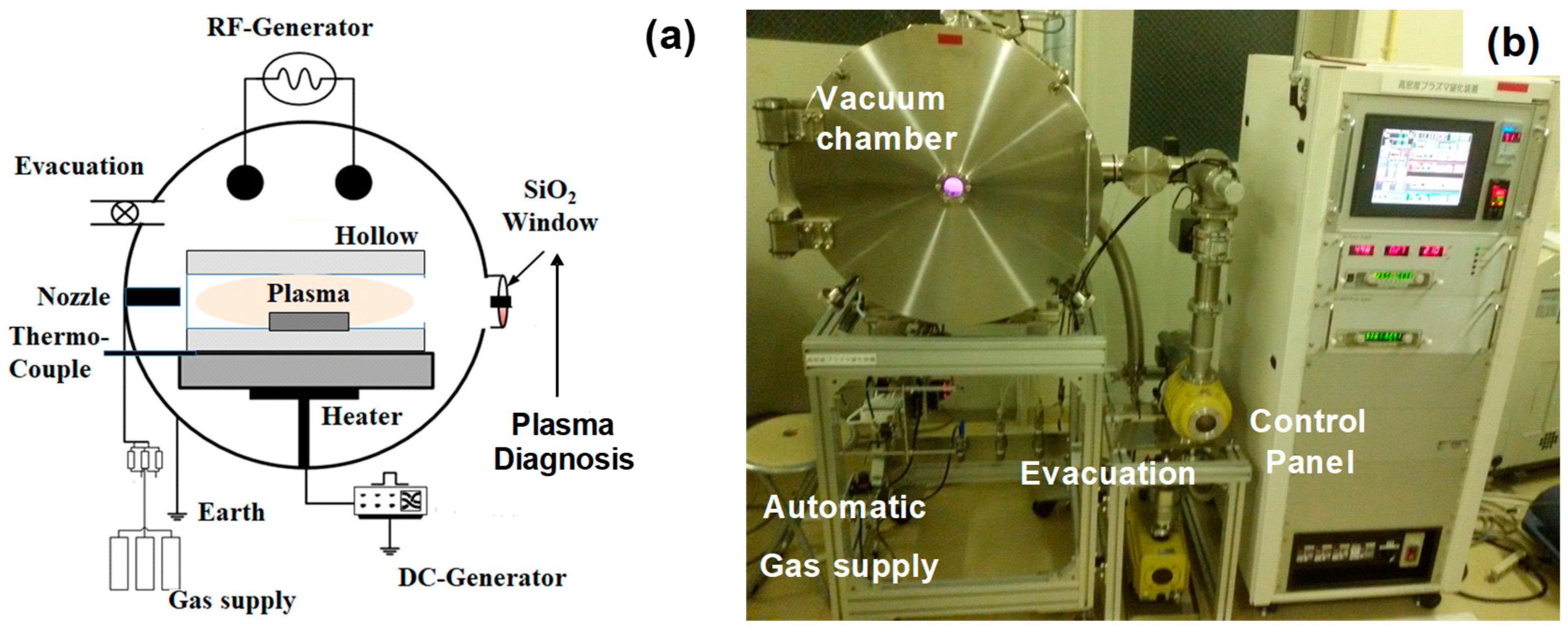
A nitrogen plasma immersion system (NS-1; YS-Electrical Industry, Co., Ltd.; Kofu, Japan) was utilized to perform the plasma nitriding of CoCrMo substrates and dies at 723 K for 21.6 ks. The plasma nitriding unit is illustrated in Figure 2a. RF (Radio Frequency) and DC (Direct Current) generators were used to ignite the nitrogen–hydrogen plasmas at the specified temperature and pressure. Through a optically flat silica window, the plasma state was monitored for plasma diagnosis. A hollow cathode device was employed to densify the nitrogen ion and NH radical populations, as reported in [15]. The gas flow rate was automatically controlled to maximize the ratio of the NH-radical population to the nitrogen ion population after this plasma diagnosis.
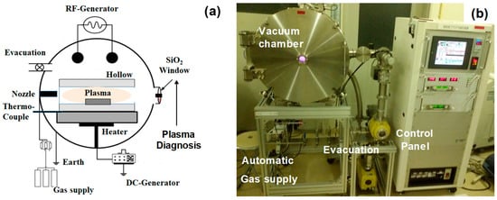
Figure 2.
Plasma immersion nitriding system for massive nitrogen supersaturation in CoCrMo substrates. (a) Schematic view on the experimental setup and (b) overview of the whole system.
The thermal transient was also monitored by using the thermocouple, which was embedded into the base plate below the hollow. As shown in Figure 2b, this plasma nitriding system consisted of the vacuum chamber, the automatic gas supply, the evacuation unit, and the control panel. The temporal mismatch between the input and output powers was self-adjusted by automatically tuning the frequency around 2.08 MHz.
In the MNS-process, the CoCrMo disc dies were fixed into a hollow cathode before evacuation to a base pressure of 0.1 Pa. After heating up to 723 K in a nitrogen atmosphere, the nitrogen gas was introduced for presputtering using a DC-bias of only −500 V. The nitrogen and hydrogen gas flow rates were 160 mL/min and 30 mL/min, respectively. After presputtering at 723 K by 60 Pa for 1.8 ks, the MNS-process was performed at 723 K at 60 Pa for 21.6 ks. Both the RF- and DC-plasmas were utilized under an RF-voltage of +250 V and a DC-bias of −500 V. After nitriding, the experimental setup was cooled down to RT under a nitrogen atmosphere. The average surface roughness was increased from 0.2 μm to 0.8 μm by this MNS process. The MNSed CoCrMo die was mechanically polished for the following forging experiments.
2.3. Dry, Cold Forging Experiment
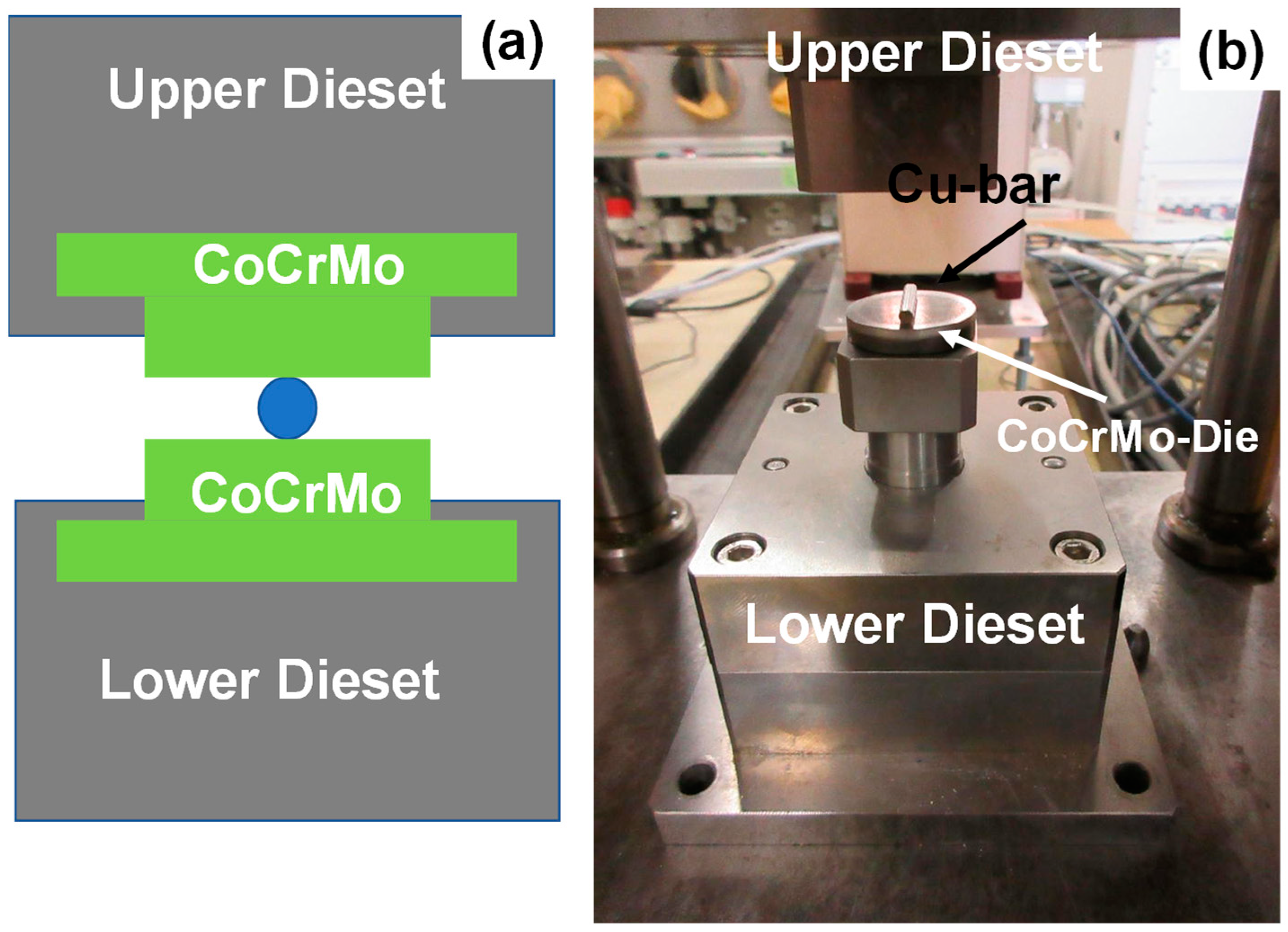
An MNSed CoCrMo cylindrical substrate pair was utilized as the upper and lower dies in the upsetting process. These dies were, respectively, locked into the upper and lower die sets for upsetting experiments to a specified reduction in thickness (r) of r = 10%, 20%, 30%, 50%, and 70% in a single stroke, as depicted in Figure 3. In the continuous forging testing, this reduction of thickness was fixed to be r = 70% to describe the adhesion behavior at the hot spot on the contact interface of the MNSed CoCrMo die.

Figure 3.
CNC-stamping system for dry, cold forging experiment of oxygen-free copper bars with the use of MNS-CoCrMo dies. (a) Schematic view of the upsetting procedure and (b) overview of the whole forging system.
2.4. Material and Mechanical Characterization on MNS CoCrMo Substrates
SEM (JOEL, Tokyo, Japan)–EDX (JOEL, Tokyo, Japan) was utilized to analyze the cross-sectional microstructure of the MNS-CoCrMo die substrates and to perform nitrogen mapping on their cross-section. EBSD (Shimazu, Kyoto, Japan) was used to analyze the modified microstructure via an IQ (Image Quality) map, the plastic straining via the KAM (Kernel Angle Misorientation) distribution, and the crystallographic structure via IPF (inverse pole-figure), respectively. In particular, the IQ map was employed to distinguish the nano-grained and buffer layers and to describe the plastically straining slip-line field as well as the grain and zone boundaries. IQ is very sensitive to the presence of defects such as boundaries and local plastic strains.
Micro-Vickers hardness testing was employed to describe the surface hardness variation with increases in the applied load of up to 20 N.
3. Results
3.1. MNSed CoCrMo Substrates
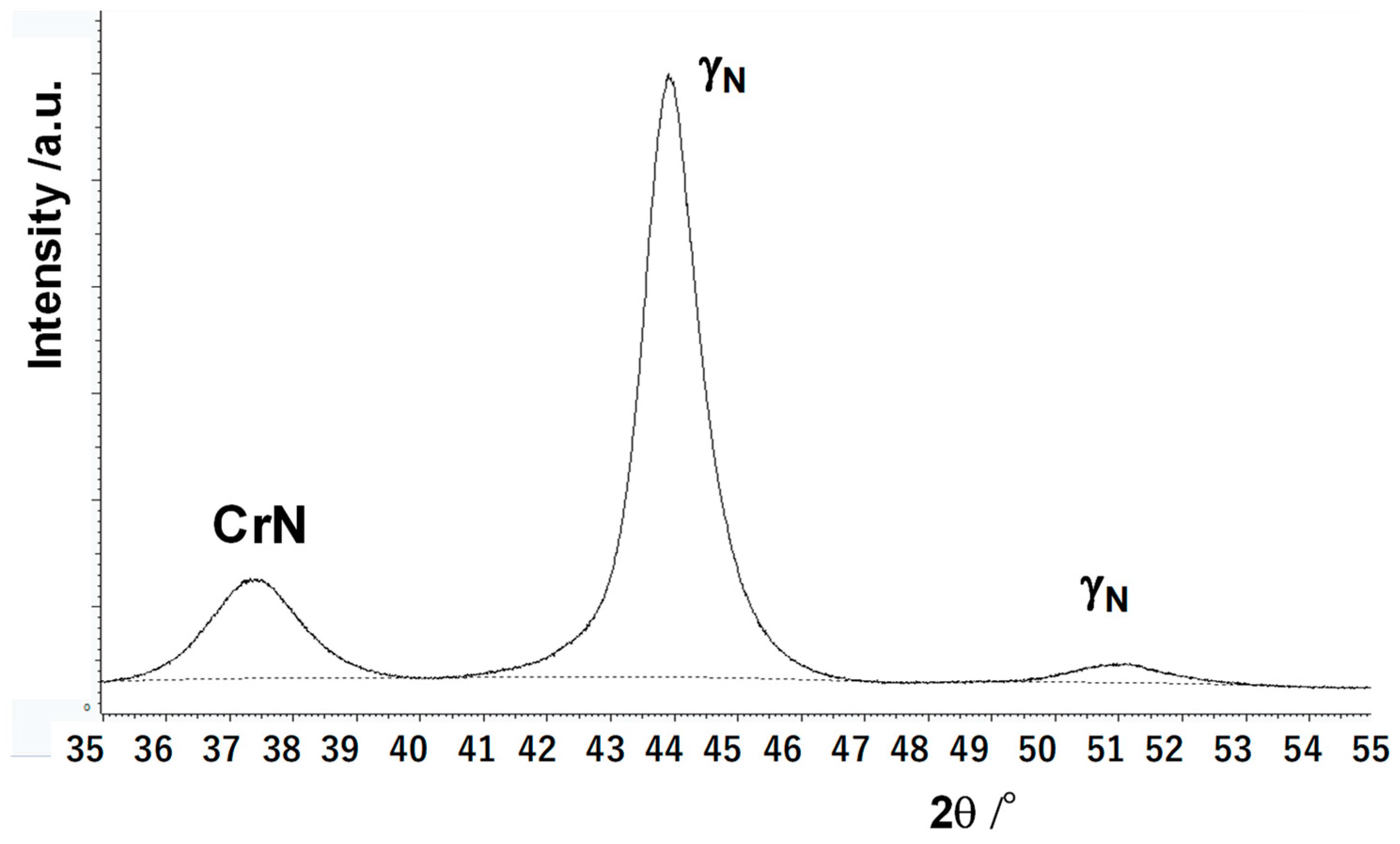
XRD was utilized to describe nitrogen supersaturation and chromium nitride (CrN) formation via plasma nitriding at 723 K for 21.6 ks.
The XRD diagram of the original CoCrMo superalloy before MNS was characterized by two austenitic peaks at 2θ = 44° and 2θ = 51°, respectively. Since no significant peak shifts were detected in Figure 4, the nitrogen solutes were contained in the cluster- and grain-boundaries in the MNSed CoCrMo. A CrN peak was also detected slightly in Figure 4. Every peak significantly broadened; as such, the MNSed CoCrMo must be finely grained [16].
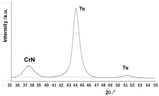
Figure 4.
XRD analysis on the MNSed CoCrMo die surface.
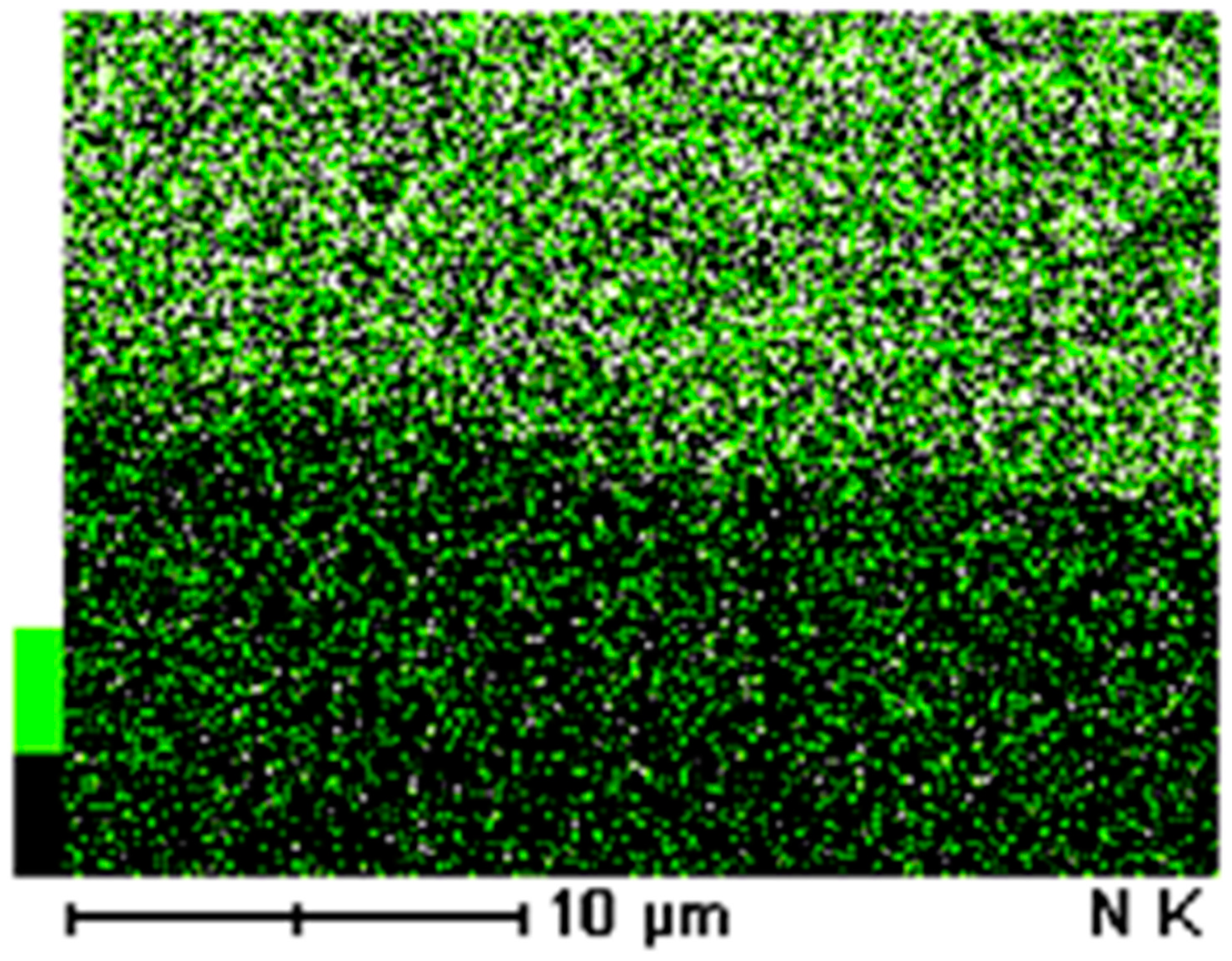
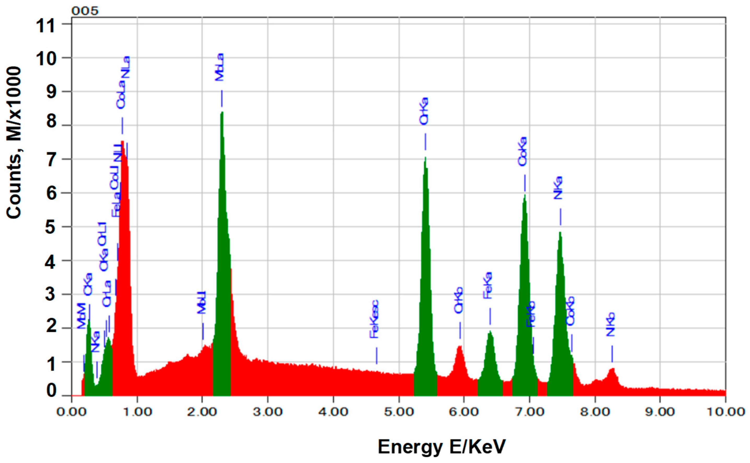
SEM–EDX was utilized to analyze the microstructure and nitrogen mapping of the cross-section of the CoCrMo dies. Figure 5 shows the nitrogen mapping on the top and side surfaces of the MNSed CoCrMo die. The nitrogen solute distributed homogeneously. The pointwise EDX analysis was performed at a depth of 10 μm from the surface. An energy profile detected by EDX was shown in Figure 6. As stated in [17], light elements—including nitrogen—were difficult to detect in the energy profile using EDX. By increasing sensitivity to the low energy spectrum, a nitrogen peak was detected in Figure 6 at an energy of 0.39 eV. In the following section, a pointwise analysis is performed to describe the nitrogen content profile from the surface to the depth all through the MNSed layer.

Figure 5.
SEM–EDX analysis on the cross-section of the MNS CoCrMo dies.

Figure 6.
Energy profile detected by EDX at a depth of 10 μm from the surface. Nitrogen was detected at an energy of 0.39 keV with higher intensities of oxygen.
As depicted in Figure 7, a higher nitrogen content than 5 at% was distributed down to a depth of 20 μm. Below this layer thickness, a nitrogen solute content of 3 at% was kept constant in depths of than 100 μm. This nitrogen solute depth profile implies that the original microstructure of the bare CoCrMo die was significantly affected by MNS, with a dependence on the nitrogen content at each depth.
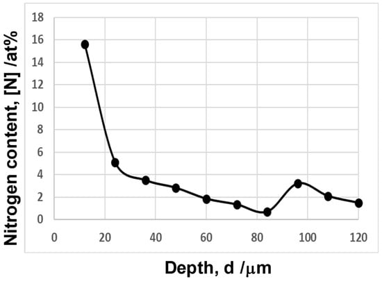
Figure 7.
Nitrogen content depth profile from the surface to a depth of 120 μm.
EBSD was utilized to describe the microstructure modification at a cross-section of the MNSed CoCrMo die. Figure 8, respectively, shows the image quality (IQ) map in Figure 8a, the IPF profile in Figure 8b, and the KAM distribution or plastic strain map in Figure 8c from the surface to a depth of 700 μm. The surface layer, with a thickness of 20 μm, had a nano-sized granular structure corresponding to a black-out zone in the IQ map in Figure 8a; multi-colored, fine patches in the IPF in Figure 8b; and severe plastic strains in Figure 8c, respectively. This nanostructured layer was followed by an intensely textured layer with high plastic strains down to far depths across the thin buffer layer, with a width of 5 μm. Below the textured layer, the original crystallographic structure of the bare CoCrMo matrix could not be observed in Figure 8.
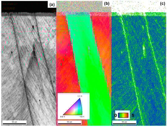
Figure 8.
Microstructure on the cross-section of the MNS-CoCrMo dies observed by EBSD analysis. (a) Image quality (IQ) map, (b) inverse pole figure (IPF) profile, and (c) KAM profile.
In this textured layer, each grain had highly strained slip-lines, as respectively represented by black lines in Figure 8a and by high KAM lines in Figure 8c. This proves that every zone in each grain was plastically strained to change their crystallographic orientation. As depicted in Figure 8b, the color grading in the IPF profile proves that each zone in each grain spin-rotated with plastic straining via geometric distortion to have different crystallographic orientations. In particular, the plastic strains concentrated with the highly textured grains at a depth of 600 μm. This reveals that MNS advanced to a depth of 700 μm at 723 K for 21.6 ks to modify the original CoCrMo microstructure. This also suggests that the impinging nitrogen solutes diffused from the surface to this depth via the highly strained zone boundaries during the MNS process.
Using IQ maps with different magnifications, let us analyze the buffer layer between the nano-grained surface layer with a thickness of 20 μm and the textured layer.
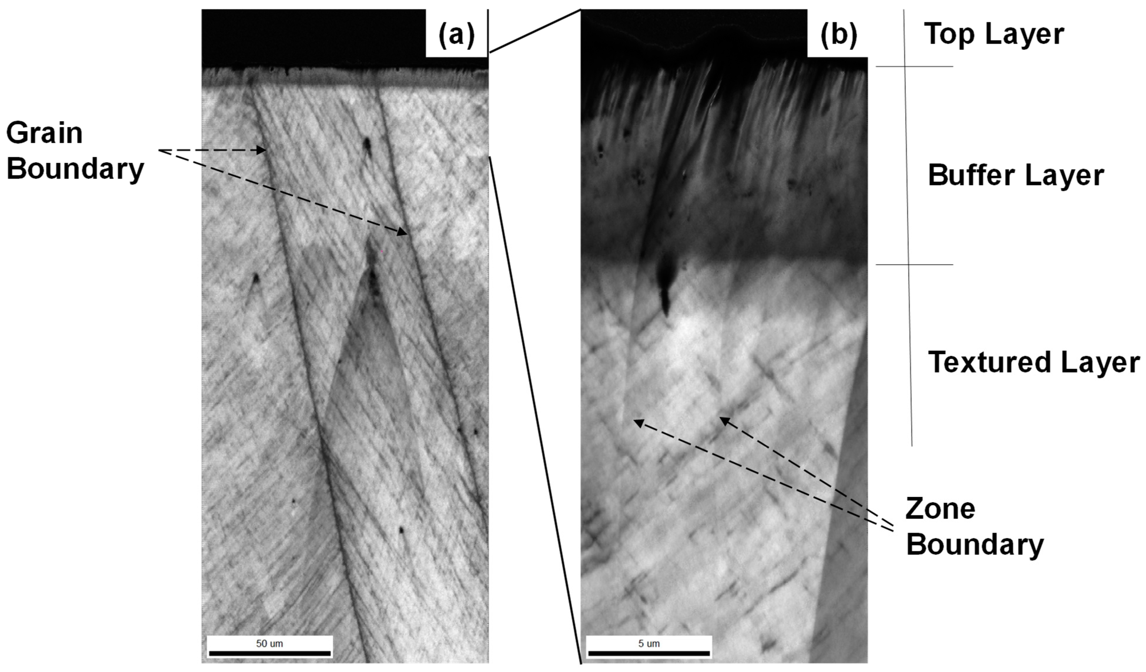
Due to the high sensitivity of the IQ to the grain and zone boundaries and the local plastic strains, each layer in the multi-layered microstructure was, respectively, characterized by the nano-granular system, the fine zone-boundaries, and the slip-line field by plastic straining in Figure 9. The top layer was defined by a black-out region in the IQ map. No signals were detected in the smeasurement because of significant electron scattering at the fine nanogranular boundaries. Since this top layer corresponded to a fine granular structure in the IPF map in Figure 8b, the black-out in IQ-map was induced by the nano-grain boundaries of the MNSed CoCrMo. The buffer layer was formed as a transient zone where the microstructure changed by itself from a nano-granular system to a crystallographic structure. The textured layer was defined by large and long grains with distinct grain boundaries. As depicted in Figure 8b, each grain had graded crystallographic orientations so that each grain consisted of many individual sub-grains with different crystallographic orientations. At the same time, many zone boundaries were distinguished as crossing lines in each grain. Each line corresponded to a linear zone with a high KAM in Figure 8c. All these crossing lines at the textured grains in Figure 9 were a slip-line field, induced by plastic straining during MNS. After [18], the microstructure just below the nitriding front end advancing into the depth plastically strained to compensate for the strain incompatibility in the microstructure plastically strained by MNS just above the nitriding front end. Hence, the textured layer was also characterized by this fine network of slip-line fields.
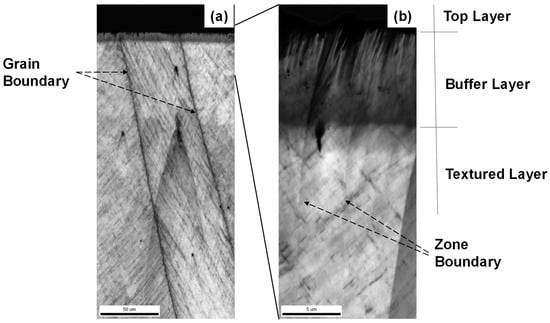
Figure 9.
IQ-map analysis of the top layer, the buffer layer, and the textured layer in the multi-layered microstructure system. (a) IQ map in low magnification and (b) IQ map in high magnification.
The buffer layer was affected by these two layers. In Figure 9, the black-out state of the IQ gradually changed to a granular structure. This implies that the nano-grain boundaries gradually disappeared and converged to each subgrain in this buffer layer. Through this conversion process, lots of subgrains were assembled into a single granular set with different crystallographic orientations.
To be discussed, the grain- and zone-boundaries as well as the slip-line fields in Figure 8 and Figure 9 were absent in the original CoCrMo substrate before MNS. They were all induced by the plastic straining during the MNS. Lots of nano-granular boundaries in the top layer were yielded by the plastic straining in the highly dense layer. Across the buffer layer, these nano-grain boundaries affected by the plastic straining decreased themselves in depth. In the textured layer, each crossing slip-line field was formed discretely from each other in the interior of large and long grains. This variation of the granular boundaries and slip-lines with the depth from the surface might control the nitrogen content as a nitrogen diffusion path into the depth of the CoCrMo matrix.
3.2. Hardness of MNS-CoCrMo Substrates
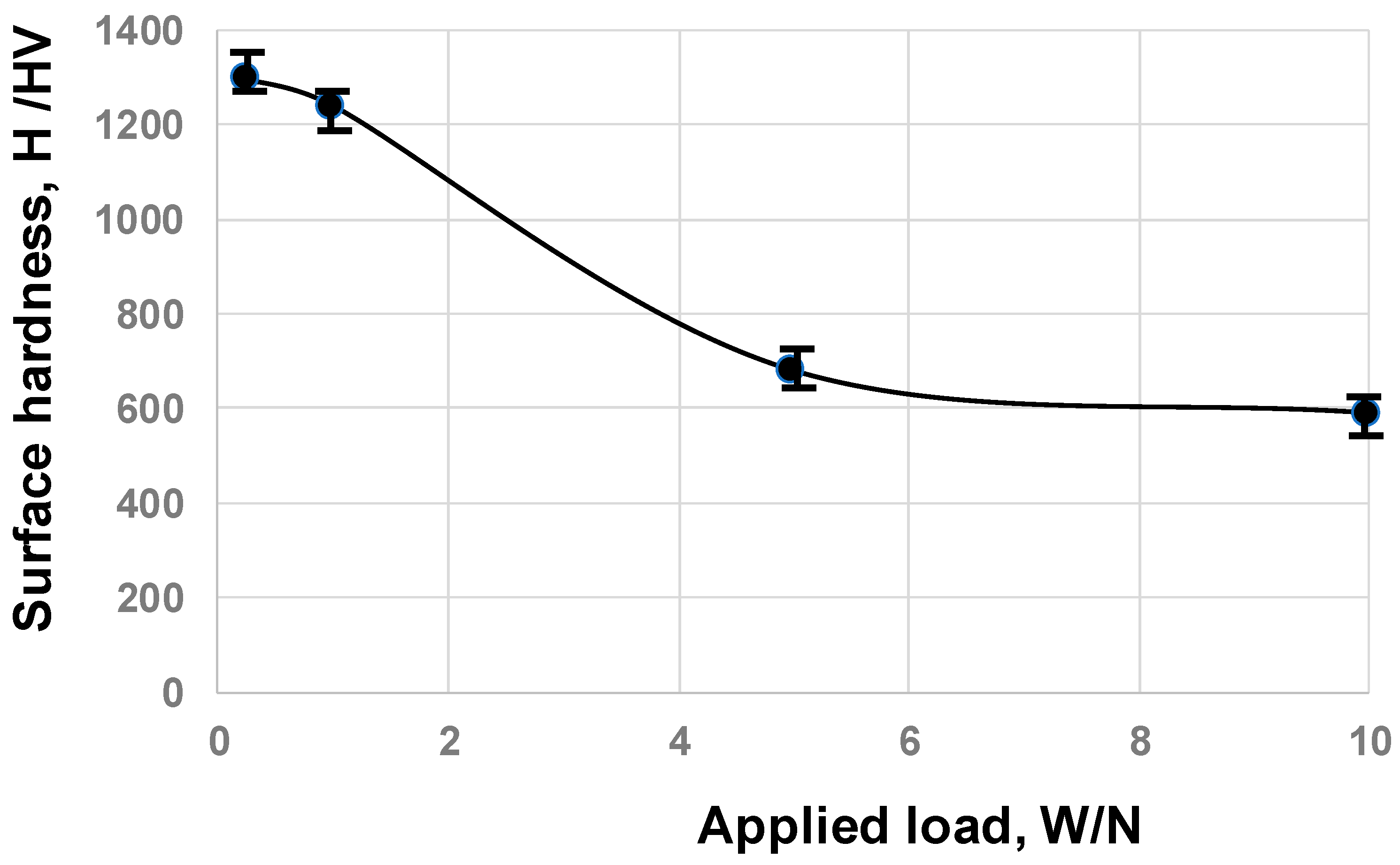
Micro-Vickers hardness testing was performed to measure the variation of surface hardness with increases in the applied load. As reported in [19], the surface hardness profile when applying a small load was mainly governed by the surface layer hardness. Meanwhile, when increasing the applied load by up to 10N, the hardness at the depth of the matrix contributed to the measured surface hardness. As shown in Figure 10, the surface hardness reached 1300 HV1N at the nanostructured surface layer in Figure 8. Across the intensely textured matrix, this hardness monotonously decreased with increases in the applied load and saturated at 600 HV10N.
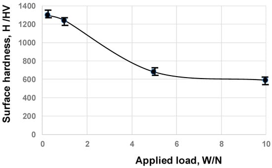
Figure 10.
Variation in the surface hardness of the MNSed CoCrMo dies when increasing the applied load in micro-hardness testing.
This implies that the intensely textured MNSed CoCrMo matrix had a higher hardness of 600 HV10N compared to the original hardness of 400 HV10N for the bare CoCrMo. The hardness higher than 1300 HV2N and the nitrogen content higher than 10 at% in Figure 7 and Figure 10 assure the wear toughness and chemical stability of the MNSed CoCrMo dies—enough to be used as a special tool for dry forging in active metal work, such as for oxygen-free pure copper.
3.3. Dry, Cold Upsetting of Oxygen-Free Copper Wires by MNSed CoCrMo Dies
A pure oxygen-free copper wire with a diameter of 1.0 mm was employed as a typical active metal work material to induce the risk of adhesive wear onto the die material. As reported in [20], when using the WC (Co) dies for piecing the copper sheets, they suffered from the adhesion of copper in the early stage of the piercing process. This onset of adhesive wear grew to severe abrasive wear between the copper adhesives on the die surface and the copper work.
The oxygen-free copper wires with a diameter of 1.0 mm were upset up to a specified reduction of thickness by r = 10%, 20%, 30%, 50%, and 70% in a single stroke, using the MSN-CoCrMo.
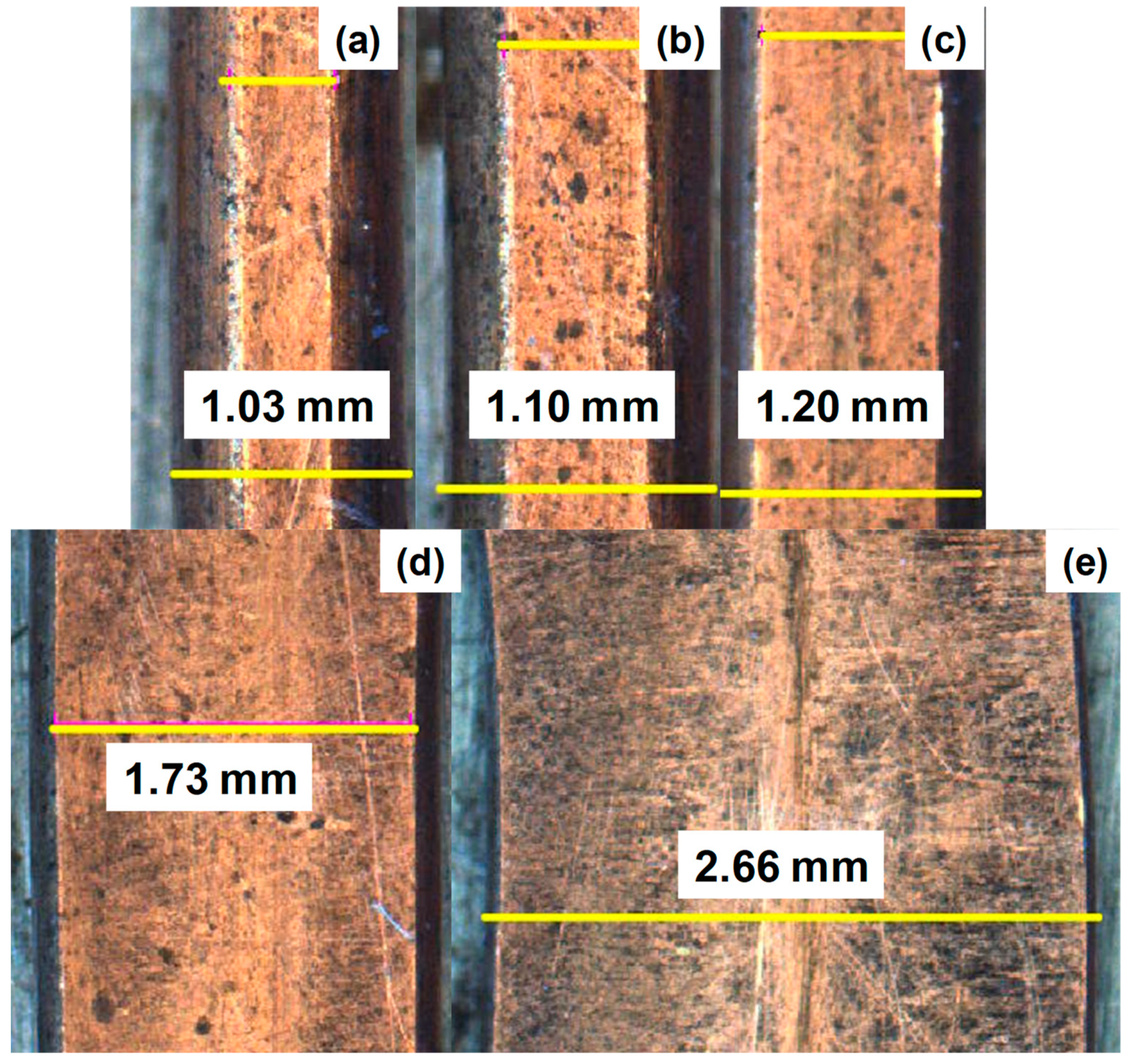
As depicted in Figure 11, the oxygen-free copper work homogeneously deformed from a wire to a plate; e.g., when the reduction in the thickness reached r = 70%, the cylindrical wire with a diameter of 1.0 mm deformed to a plate with a uniform thickness of 0.3 mm.

Figure 11.
Variation of the upset copper bars when increasing the reduction of thickness (r) up to t = 70%. (a) r = 10%, (b) r = 20%, (c) r = 30%, (d) r = 50%, and (e) r = 70%.
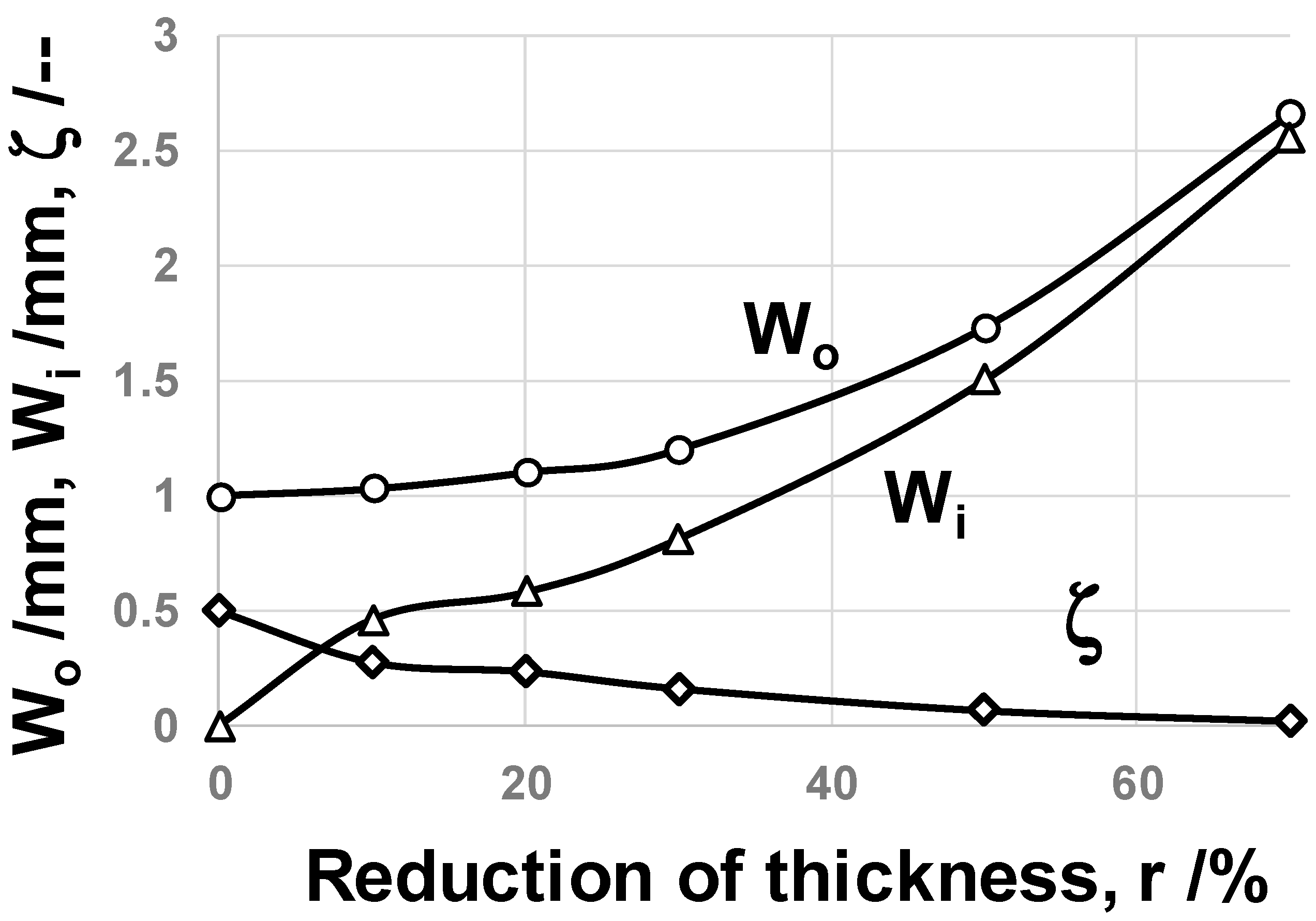
In normal upsetting with a relatively high friction coefficient on the contact interface between the punch/die and the pure copper work, the copper work has a risk of fracture by high tensile stress in the lateral direction even with low reductions in thickness of around 20 to 25% [21]. As seen in Figure 11, both the wire width (Wo) and the contact interface width (Wi) increased monotonously with r, without any fracture or damage in the work. After [22], the bulging deformation Bg (=(Wo − Wi)/2) was employed as a measure to describe the friction coefficient, as Bg decreases monotonously with reductions in the friction coefficient. Figure 12 depicts the variation of Wo, Wi, and the non-dimensional bulging deformation ζ, which was defined by ζ = (Bg/Wo), with r. ζ → 0 since the friction coefficient gradually decreases to zero with r. When r > 50%, ζ ~ 0; the oxygen-free copper work plastically flows homogeneously along the contact interface and flattens by itself. This is completely different from the normal plastic flow of pure copper, where the fresh surface of copper work easily contacts on the die, at the risk of mass adhesion to punch and die interfaces with increases in the friction coefficient. After the empirical estimate on the friction coefficient in [19], since Wo ~ Wi, or ζ ~ 0 at r > 50%, μ is estimated to be 0.05 to 0.1. In an inverse finite element analysis [23], the friction coefficient was parametrically varied in order that the calculated equivalent plastic strain distribution coincided with the hardness map. The friction coefficient was also estimated to be 0.05 at r = 50%.

Figure 12.
Variation of the outer width (Wo), the contact interface width (Wi), and the nondimensional bulging displacement (ζ) when increasing r by up to r = 70%.
This low frictional state on the contact interface of the MNSed CoCrMo die to the copper work proves that no adhesive wear or galling occurred on the contact interface and that a low frictional state was preserved even in the continuous dry forging process.
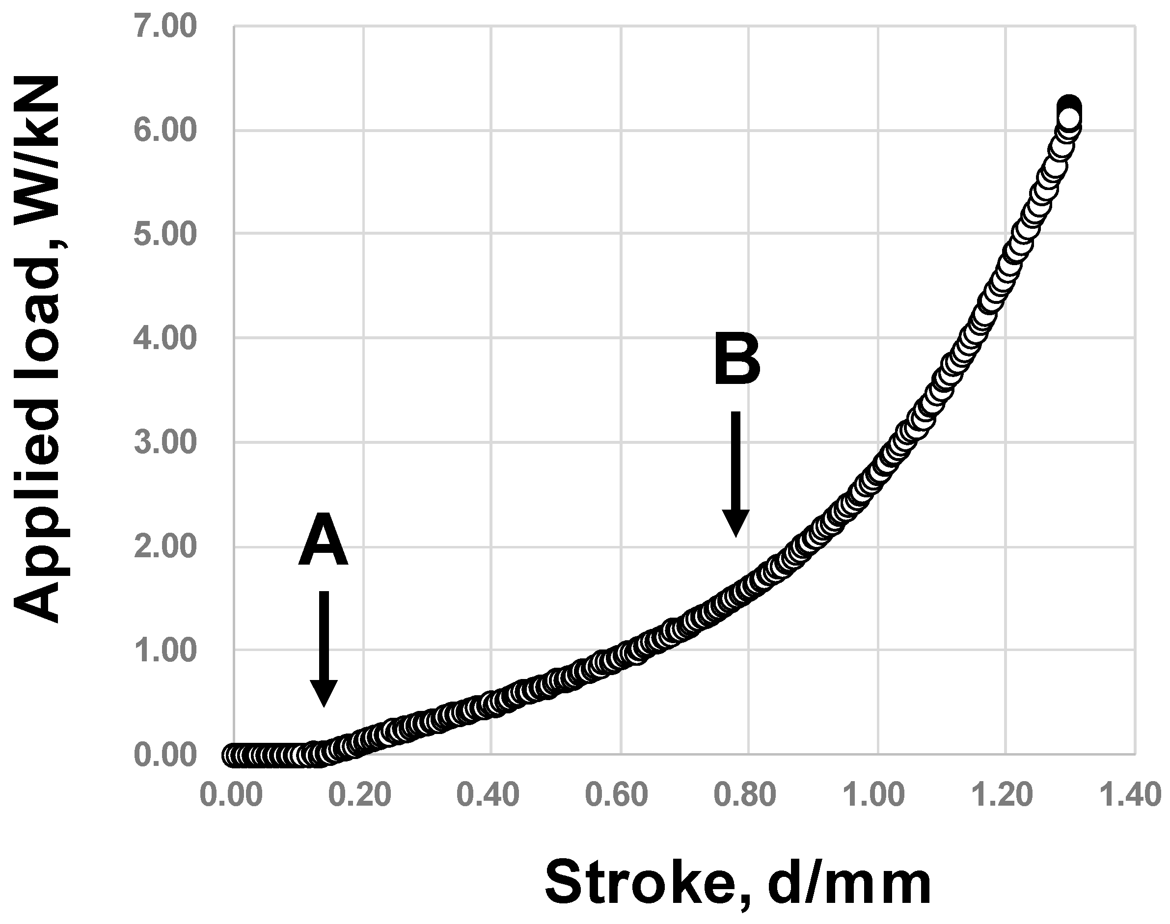
Using the load cell, which was embedded into the lower die set, the load–stroke relationship was monitored and measured during the upsetting process of the oxygen-free copper specimen. As depicted in Figure 13, the significant plastic flow commenced at A and the applied load monotonously increased with the stroke above A. This reveals that the contact interface area expands monotonically with the stroke under a nearly constant flow stress of copper work. This interfacial area expansion advanced steeply at B in Figure 13. The flattening deformation advanced with the stroke under the condition of Wi~Wo in Figure 12.
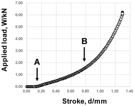
Figure 13.
Measured relationship between the applied load and stroke when upsetting the oxygen-free copper wire down to a reduction of thickness by 70%. A indicates the onset of elasto-plastic deformation of copper work, and B points the onset of flattening behavior of copper work.
4. Discussion
The original CoCrMo with an average hardness of 400 HV10N and an average grain size of 50 μm was completely modified to have a multi-layered microstructure in its cross-section with a surface hardness of 1300 HV by massive nitrogen supersaturation (MNS). In correspondence to the galling-free die design in Figure 1b, the multi-layered structure of the MNSed CoCrMo was responsible for the galling-free forging behavior even with high reductions in thickness.
As stated in Figure 9, this multi-layered microstructure was characterized by the distribution of defects such as the grain/zone-boundaries and the plastic slip-lines in its cross-section. The impinging nitrogen solutes diffused through these defects as a transportation path in the microstructure from the surface to the depth of the CoCrMo matrix. In the top layer, the nitrogen solutes homogeneously transported themselves through the fine network of nano-grain boundaries. The highest nitrogen solute content was preserved in this layer, at 10 to 20 at%. This high nitrogen content supersaturation induced the plastic strains, as proved by the high KAM in Figure 8c as well as the high fraction of grain boundaries. This nitrogen content gradually decreased by itself across the buffer layer toward the textured layer. In parallel with this, the fraction of defects (f) also decreased; the discrete zone boundaries and the discrete slip-lines were only present in the textured layer. Then, both the nitrogen content [N] and the fraction (f) of defects converged to a constant; e.g., [N] ~ 2–4 at% in Figure 7, and f was minimized by itself, since only the discrete slip-line field was present, as shown in Figure 8 and Figure 9.
For simplicity, f is assumed to be at unity or f = 1 at d = d0 in the top layer and f = 0 in the far depth of the textured layer. Then, the variation of the fraction with depth through the buffer layer is represented by:
where d0 is the thickness of the top layer by d0 = 20 μm, and κ is the proper exponent to represent the decay of fraction across the buffer layer. Assuming that f approaches 0.01 at d = 30 μm, k is determined to be 0.46. Then, the nitrogen depth profile [N] (d − d0), as well as the hardness depth profile H (d − d0), is also thought to vary with d according to Equation (1): e.g.,
were Ndepth is a nitrogen content at a far depth and Ntop is the average nitrogen content at the top layer, and,
where Hdepth is the hardness at a far depth, or Hdepth = 600 HV, and Hsurface is the hardness at the top layer, or Hsurface = 1300 HV.
f = exp [−κ × (d − d0)]
[N] (d − d0) = Ndepth + (Ntop − Ndepth) × exp [−κ × (d − d0)]
[H] (d − d0) = Hdepth + (Hsurface − Hdepth) × exp [−κ × (d − d0)]
Let us compare this estimate by Equation (2) with the experimentally measured nitrogen content depth profile in Figure 7. Assuming that Ndepth = 2 at% and Ntop = 15 at%, [N] is estimated by [N] (0) = 15 at%, [N] (5) = 3.3 at%, [N] (10) = 2.13 at%, [N] (15) = 2.01 at%, and [N] (20) = 2.00 at%. Figure 7 proves that this calculated [N] (d − d0) profile by Equation (2) is in fairly good correlation with the experimentally measured nitrogen content in Figure 7. That is, nitrogen solutes diffuse through the defective paths into the depths of CoCrMo with f (d − d0), and each nitrogen content in the depths is determined by f (d − d0).
The hardening process of the nano-granular system changed to the work-hardening process by f (d − d0) through the buffer layer to the textured layer. A high surface hardness at the top layer and a hardness depth profile higher than 600 HV10N played a role in suppressing the abrasive wear, even in the continuous forging of active metals including the oxygen-free copper.
Let us consider a role of the supersaturated nitrogen content at the top layer in galling-free forging. Remembering that no significant peak shift was detected in the XRD diagram in Figure 3, the supersaturated nitrogen solute was once contained in the inside of the grains to induce the plastic strains, and promptly diffused from the inside of the nano-grained clusters into the nano-grain boundaries during the MNS process. The first-principle calculation on the nitrogen supersaturated iron reveals that iron atoms are much attracted by supersaturated nitrogen solute atoms—enough to reduce the chemical activity of the irons in the work materials [24]. As estimated using molecular dynamics [25], no adhesion of work materials to the die surface occurs when no essential potential is present between two constituent atoms in both materials. These theoretical studies reveal that nitrogen solute, at a high content, acts to protect the die surface from nucleation by fresh copper debris fragments on the die surface. After experimental studies on nitrogen supersaturated stainless steels [26] and CoCr alloys [27], their corrosion toughness was significantly improved by nitrogen supersaturation. This finding also proves that the MNSed CoCrMo top layer has sufficient adhesive wear resistance against active metals due to its chemical inertness.
No adhesion of copper debris from fresh work materials onto MNSed CoCrMo suggests that this dry forging of oxygen-free copper works may be free from abrasive wear and damage in continuous forging operations. The high hardness of the nanograined top layer has sufficient robustness and chemical inertness to sustain the galling-free condition even in long usage.
A bare CoCrMo superalloy has been utilized as an artificial knee joint material [28,29] and as an extrusion die material [30]. As stated in [31], higher hardness and strength is needed to improve the wear resistance of joints and to increase their fracture toughness. MNSed CoCrMo joints and dies provide a solution to satisfy those needs in medical and engineering applications. The top layer of MNSed CoCrMo joints is expected to work as a bioactive layer in vivo. Under the chemical inertness and high surface hardness shown by MNS, the extrusion temperature can be lowered to suppress the onset of tearing fractures.
In the MNS process, both the holding temperature and the pressure can be optimized to control CrN formation during MNS. Further studies are necessary to find out the CrN-free MNS conditions and to improve surface hardness and chemical inertness.
5. Conclusions
A massively nitrogen supersaturated (MNSed) CoCrMo substrate is proposed as a multi-layered die for dry, galling-free forging. This multi-layered die-material system consists of a nano-structured top layer, a buffer layer, and an intensely textured layer in the CoCrMo matrix. A high surface hardness of up to 1300 HV and a high nitrogen solute content of 16 at% were attained in this nano-grained top layer with a thickness of 20 μm. The intensely textured layer contributed to the hardness depth profile by +200 HV to 400 HV for a bare CoCrMo matrix. The nitrogen content depth profile proves that this multi-layered structure is induced by MNS with nitrogen solute diffusion to the depths of the structure via the grain/zone boundaries and slip-line fields.
The oxygen-free copper wires were upset in dry forging without any adhesive wear down to a reduction in thickness of 70% in a single stroke. This plastic flow with μ = 0.05 to 0.1 proves that no galling occurred during this upsetting process. The MNSed layer with a nanostructure had sufficient strength and chemical inertness to suppress abrasive and adhesive wear in the dry forging of active metals and alloys.
Author Contributions
Conceptualization, T.A.; methodology, T.A. and T.S.; validation, T.A., T.F. and T.S.; formal analysis, T.A.; investigation, T.A. and T.F.; resources, T.S.; data curation, T.A.; writing-original draft preparation, T.A.; writing—review and editing, T.F. and T.S.; supervision, T.S. All authors have read and agreed to the published version of the manuscript.
Funding
This research received no external funding.
Data Availability Statement
Publicly available datasets were analyzed in this study.
Acknowledgments
The authors would like to express their gratitude to Kurozimi S-I. (Nano Film Coat, LLC), Nasu T. (Ebinax, Co., Ltd.) and Fukuda T. (Tokai Engineering Service, Co., Ltd.) for their help in experiments.
Conflicts of Interest
The authors declare no conflicts of interest.
References
- Lei, T.; Wang, D.; Yu, X.; Ma, S.; Zhao, W.; Cui, C.; Meng, J.; Tao, S.; Guan, D. Global iron and steel plant CO2 emissions and carbon-neutrality pathways. Nature 2023, 622, 514–520. [Google Scholar] [CrossRef] [PubMed]
- Hagedorn, W.; Gramlich, A.; Greiff, K.; Krupp, U. Alloy and process design of forging steels for better environmental performance. Sustain. Mater. Technol. 2022, 34, e00509. [Google Scholar] [CrossRef]
- Global Market Insights. Market Size and Share of Oxygen-Copper. Available online: https://www.gminsights.com (accessed on 22 May 2024).
- Cui, Z.P.; Li, G.; Liu, H.Z.; Zong, W.J.; Zhang, H.J.; Zhang, C.Y.; Du, K. Tool anisotropic wear prediction and its influence on surface topography in diamond turning of oxygen-free copper. J. Mater. Process. Technol. 2023, 318, 118042. [Google Scholar] [CrossRef]
- Dohda, K.; Boher, C.; Rezai-Aria, F.; Mahayotsanun, N. Tribology in metal forming at elevated temperatures. Friction 2015, 3, 1–27. [Google Scholar] [CrossRef]
- Dohda, K.; Yamamoto, M.; Hu, C.; Dubar, L.; Ehmann, K.F. Galling phenomena in metal forming. Friction 2021, 9, 665–685. [Google Scholar] [CrossRef]
- Siegmund, M. Hot die forging with nitrided and thermally stabilized DLC coated tools. Mater. Res. Proc. 2023, 28, 583–590. [Google Scholar]
- Dumpala, R.; Chandran, M.; Ramachandra Rao, M.S. Engineered CVD diamond coatings for machining and tribological applications. JOM 2015, 67, 1565–1577. [Google Scholar] [CrossRef]
- Choleridis, A.; Sao-Joao, S.; Ben-Mohamed, J.; Chern, D.; Barnier, V.; Kermouche, G.; Heau, C.; Leroy, M.-A.; Julien Fontaine, J.; Sylvie Descartes, S.; et al. Experimental study of wear-induced delamination for DLC coated automotive components. Surf. Coat. Technol. 2018, 352, 549–560. [Google Scholar] [CrossRef]
- Zhao, G.; Li, Z.; Hu, M.; Li, L.; He, N.; Jamil, M. Fabrication and performance of CVD diamond cutting tool in micro milling of oxygen-free copper. Diam. Relat. Mater. 2019, 100, 107589. [Google Scholar] [CrossRef]
- Moskalioviene, T.; Galdikas, A.; Rivière, J.P.; Pichon, L. Modeling of nitrogen penetration in polycrystalline AISI 316L austenitic stainless steel during plasma nitriding. Surf. Coat. Technol. 2011, 205, 3301–3306. [Google Scholar] [CrossRef]
- Aizawa, T. Micro-/meso-structure control of multi-hostmetal alloys by massive nitrogen supersaturation. J. Mater. 2024, 17, 1294. [Google Scholar] [CrossRef] [PubMed]
- Aizawa, T.; Funazuka, T.; Shiratori, T.; Suzuki, Y. Massive nitrogen supersaturation to CoCrMo alloys for surface microstructure control. Acad. Mater. Sci. 2023, 1, 1–9. [Google Scholar] [CrossRef]
- Aizawa, T.; Fukuda, T.; Shiratori, T.; Suzuki, Y. Massive nitrogen supersaturation into CoCrMo alloys for improvement of tribological performance. In Proceedings of the 26th ESAFORM, Toulouse, France, 25 April 2024; Materials Research Proceedings. Volume 41, pp. 1248–1258. [Google Scholar]
- Aizawa, T.; Rsadi, I.; Yunata, E.E. High density RF-DC plasma nitriding under optimized conditions by plasma diagnosis. Appl. Sci. 2022, 12, 3706. [Google Scholar] [CrossRef]
- He, K.; Chen, N.; Wang, C.; Wei, L.; Chen, J. Method for determining crystal grain size by X-ray diffraction. Cryst. Res. Technol. 2018, 53, 1700157. [Google Scholar] [CrossRef]
- Fernanda Gazulla, F.; Rodrigo, M.; Blasco, E.; Orduña, M. Nitrogen determination by SEM-EDS and elemental analysis. X-ray Spectrosc. 2013, 42, 394–401. [Google Scholar] [CrossRef]
- Li, Y.; Li, W.; Min, N.; Liu, H.; Jin, X. Homogeneous elasto-plastic deformation and improved strain compatibility between austenite and ferrite in a co-precipitation hardened medium Mn steel with enhanced hydrogen embrittlement resistance. Int. J. Plast. 2020, 133, 102805. [Google Scholar] [CrossRef]
- Frueh, P.; Heine, A.; Weber, K.E.; Wickert, M. Effective depth-of-penetration range due to hardness variation for different lots of nominally identical target material. Def. Technol. 2016, 12, 171–176. [Google Scholar] [CrossRef]
- Mikado, H.; Lindgren, J.H.; Wiklund, U.; Jacobson, S.; Kawamura, S. Wear of cemented carbide tools in a copper alloy forging process—Verification of a new lab test. Wear 2023, 528–529, 204978. [Google Scholar] [CrossRef]
- Artizono. Copper Alloy Forging: A Comprehensive Guide. Available online: https://artizono.com/copper-alloy-forging-guide/ (accessed on 24 May 2024).
- Hong, J.-J.; Yeh, W.-C. Application of response surface methodology to establish friction model of upset forging. Adv. Mech. Eng. 2018, 10, 1687814018766744. [Google Scholar] [CrossRef]
- Franchi, R.; Prete, A.D.; Umbrello, D. Inverse analysis procedure to determine flow stress and friction data for finite element modeling of machining. Int. J. Mater. Form. 2017, 10, 685–695. [Google Scholar] [CrossRef]
- Domain, C.; Becqart, C.S.; Foct, J. Ab initio study of foreign interstitial atom (C, N) interactions with intrinsic point defects in α-Fe. Phys. Rev. B 2004, 69, 144122. [Google Scholar] [CrossRef]
- Kitano, H.; Dohda, K.; Kalin, M.; Ehmann, K.F. Galling growth analysis in metal forming. Manuf. Lett. 2018, 16, 32–35. [Google Scholar] [CrossRef]
- Borgioli, F.; Galvanetto, E.; Bacco, T. Low temperature nitriding of AISI300 and 200 series austenitic stainless steels. Vacuum 2016, 12, 51–60. [Google Scholar] [CrossRef]
- Dong, H. S-phase surface engineering of Fe-Cr, Co-Cr and Ni-Cr alloys. Int. Mater. Rev. 2022, 55, 65–98. [Google Scholar] [CrossRef]
- Bandyopaghyay, A.; Traxel, K.D.; Avila, J.D.; Mitra, I.; Bose, S. CoCr alloys. In Biomaterials Science, 4th ed.; Academic Press: Cambridge, MA, USA, 2020; pp. 257–269. [Google Scholar]
- Lee, S.; Nomura, N.; Chiba, A. Significant improvement in mechanical properties of biomedical Co-Cr-Mo alloys with combination of N addition and Cr-enrichment. Mater. Trans. 2008, 2, 260–264. [Google Scholar] [CrossRef]
- Funazuka, T.; Horiuchi, S.; Dohda, K.; Shiratori, T. Effect of CoCrMo die with nanotexture applied on micro-extrudability of micro backward extrusion of AA6063. In Proceedings of the WCMNM2023, Evanston, IL, USA, 19 September 2023; pp. 1–4. [Google Scholar]
- Shukla, K.; Sugumaran, A.A.; Khan, I.; Ehiasarian, A.P.; Hovsepian, P.E. Low pressure plasma nitrided CoCrMo alloy utilizing HIPIMS discharge for biomedical applications. J. Mech. Behav. Biomed. Mater. 2020, 111, 104110. [Google Scholar] [CrossRef]


Disclaimer/Publisher’s Note: The statements, opinions and data contained in all publications are solely those of the individual author(s) and contributor(s) and not of MDPI and/or the editor(s). MDPI and/or the editor(s) disclaim responsibility for any injury to people or property resulting from any ideas, methods, instructions or products referred to in the content. |
© 2024 by the authors. Licensee MDPI, Basel, Switzerland. This article is an open access article distributed under the terms and conditions of the Creative Commons Attribution (CC BY) license (https://creativecommons.org/licenses/by/4.0/).