Article

Experimental Characterization and Phase-Field Damage Modeling of Ductile Fracture in AISI 316L

by
Vladimir Dunić
1,*,
Nenad Gubeljak
2,
Miroslav Živković
1,
Vladimir Milovanović
1,
Darko Jagarinec
2 and
Nenad Djordjevic
3
1
University of Kragujevac, Faculty of Engineering, 34000 Kragujevac, Serbia
2
Faculty of Mechanical Engineering, University of Maribor, SI-2000 Maribor, Slovenia
3
Centre for Assessment of Structures and Materials under Extreme Conditions, Department of Mechanical and Aerospace Engineering, Brunel University London, London UB8 3PH, UK
*
Author to whom correspondence should be addressed.
Metals 2024, 14(7), 787; https://doi.org/10.3390/met14070787
Submission received: 30 May 2024 / Revised: 1 July 2024 / Accepted: 2 July 2024 / Published: 5 July 2024

Abstract

:
(1) Modeling and characterization of ductile fracture in metals is still a challenging task in the field of computational mechanics. Experimental testing offers specific responses in the form of crack-mouth (CMOD) and crack-tip (CTOD) opening displacement related to applied force or crack growth. The main aim of this paper is to develop a phase-field-based Finite Element Method (FEM) implementation for modeling of ductile fracture in stainless steel. (2) A Phase-Field Damage Model (PFDM) was coupled with von Mises plasticity and a work-densities-based criterion was employed, with a threshold to propose a new relationship between critical fracture energy and critical total strain value. In addition, the threshold value of potential internal energy—which controls damage evolution—is defined from the critical fracture energy. (3) The material properties of AISI 316L steel are determined by a uniaxial tensile test and the Compact Tension (CT) specimen crack growth test. The PFDM model is validated against the experimental results obtained in the fracture toughness characterization test, with the simulation results being within 8% of the experimental measurements. (4) The novel implementation offers the possibility for better control of the ductile behavior of metallic materials and damage initiation, evolution, and propagation.

1. Introduction

Characterization and predictive modeling of fracture in metals is instrumental for structural design, in terms of both the development of new structures and in life assessment and health monitoring of existing structures. For instance, the fitness of the metallic materials assessment is essential for the safety of a range of structures in the mechanical engineering industry—such as cast tools and machine parts—and in other engineering industries; for example, the oil and gas sector, ship building, bridge and dam construction, etc. Fracture occurs for a number of reasons, including overload, cyclic loading, dynamic loading, and impact; as well as the degradation of materials’ properties and the development of initial cracks in the material, which are a result of the environmental conditions. Many structures are critical infrastructural objects that are also essential parts of complex systems; therefore, predicting their current state and implementing any necessary redesign, maintenance, and replacements are crucial for safety and economic aspects. Engineers and scientists are working hard to offer the best solutions for such applications. For these reasons, a range of experimental techniques and numerical models have been developed to date, which are combined into verification and validation to offer better insight in structures’ behavior at an early stage of the design process.
AISI 316L is austenitic stainless steel used in various processing industries due to its abrasion resistance, corrosion resistance, and excellent performance over a wide temperature range. Despite its high toughness, crack propagation does occur under plane stress conditions. Crack growth is accompanied by pronounced plastic deformation, which actually represents the already martensitic microstructure of the material. Experimental investigation has been well developed, and a set of ASTM and BSI standards have been dedicated to fracture and engineering critical assessment; this includes determination of the crack-mouth (CMOD) and crack-tip (CTOD) opening displacement as a function of applied force or crack growth [1]. Garcia-Gonzalez et al. [2] published a carefully selected review of articles related to the role of crack-tip plasticity in crack growth. They identified the advantages and limitations of the existing numerical simulations and analytical calculation tools for analysis of crack propagation. Ajmal et al. [3] investigated a crack growth caused by fatigue and proposed a new approach which takes into account the plastic contribution to the material response and CTOD. They correlated displacement field with post-processing digital images. Compact Tension (CT) specimens were investigated and the linear relationship between the propagation rate and CTOD is recorded. Khor [4] investigated the fracture toughness of high-strain-hardening materials. Finite Element Method (FEM) simulations were validated against the experimental results. CTOD was analyzed by FEM, and the experiments followed the BS 7448 [5], ISO 12135 [6], ASTM E1820 [7], and WES 1108 standards [8]. The presented results enable fracture characterization for a range of engineering materials. Whilst the experimental standard-based investigation of fracture properties is still very trustworthy within industrial circles, it is time consuming and requires expensive equipment and a large number of specimens tested. These shortcomings can be efficiently avoided by using well-developed validated predictive simulation methods.
A number of computational techniques and software tools for predictive modeling of fracture have been developed in recent decades, including both in-house developed codes and commercial solutions. Among the models of interest is the state-of-the-art Phase-Field Damage Modeling (PFDM) technique, based on the Griffith theory [9], which can be conveniently employed in a FEM code. The PFDM is based on a variational principle and minimization of total strain energy. The application of the method to fracture simulation has been recently demonstrated in [10,11], where the experimental and the simulation results for Compact Tension (CT) and Single Edge Notched Bend (SENB) tests were compared. A suitable choice of the characteristic length scale led to the correct prediction of brittle crack initiation and propagation. Khandelwal and Ramachandra Murthy [12] investigated ductile fracture simulation using PFDM, with various damage models and different degradation and geometric crack functions. They successfully simulated behavior of the specimen and compared the performance of several PFDM models. Yin and Kaliske [13] proposed a ductile PFDM for small strain problems, based on degradation of the fracture toughness. They proposed a new ductile PFDM with the fracture toughness defined as a function of the accumulated plastic strain. Eldahshan et al. [14] offered a solution for ductile fracture in large plastic strain problems, with adaptive isotropic remeshing. A number of numerical examples were proposed and demonstrated the capability of the developed models in predicting fracture in ductile materials. Whilst these papers show that PFDM could be used for the prediction of fracture in ductile materials, there is still room for the numerical models’ improvement. Ambati et al. in [15] presented a PFDM for ductile fracture of elastic-plastic materials based on well-established framework for brittle fracture. The model proposed a coupling between the degradation function and the effective plastic strain by introducing coupling variable. In [16], Ambati et al. provided the extension of the model to the three-dimensional finite strain loading regime. The fracture occurred when a critical value of the accumulated plastic strain was achieved. Miehe et al. [17] proposed a phase-field model coupled with thermo-plasticity governed by a crack driving force which is based on elastic and plastic work densities. Huang and Gao [18] presented a new development of phase-field model for brittle and ductile fracture. They modified a crack driving force by using plastic energy and monolithically solved a fully coupled system of equations. The study of the parameters were analyzed for the effects of the increment size, the critical energy release rate, and the effect of the yield stress on the double notched, dog bone specimen. After that, additional examples were provided by using different types of specimens, such as a flat specimen without notch, and compact tension specimens. Lesičar et al. [19] introduced a universal PFDM framework for both brittle and ductile fracture. The framework is implemented as a UEL in Abaqus, which controls the global evolution process. The framework’s performance was demonstrated using the symmetrically notched specimen for ductile fracture, and the CT specimen for low and high cyclic fatigue. Liu et al. [20] used peridynamics for the simulation of ductile fracture, which was limited to the failure zone. They compared the crack modes obtained by simulations with the experimental results. Chen Y. et al. [1] investigated a number of modeling strategies for simulation of crack propagation in industrial applications. He successfully employed an improved Gurson–Tvergaard–Needleman (GTN) model for crack-tip blunting, crack initiation and large crack propagation. Chen C.-J. et al. [21] investigated experimentally hot-rolled steel Q420C and the application of cohesive zone models for the simulation of crack propagation. The recorded F–CMOD curve obtained in the monotonic loading using a 12 mm thick CT specimen was used for calibration of material parameters.
In this paper, a new PFDM-based constitutive model is implemented in the in-house FEM code PAK-DAM [22]. The simulation results were validated against the experimental results for crack-mouth (CMOD) and crack-tip (CTOD) opening displacement versus the applied force or crack growth, obtained with the standard CT specimen. More specifically, the objective of this article is to demonstrate applicability of the PFDM modeling approach to the material, where the plastic deformation features a phase transformation from metastable austenite to martensite before the crack growth. A flowchart of the experimental and simulation program is illustrated in Figure 1.
The PFDM parameters are brought closer to the practical application. The martensitic properties are taken into account for the model. In the proposed model, instead of the specific fracture energy—which is not easy to determine from the experimental results—the critical total strain controls the influence of bulk energy density on damage initiation and propagation. Consequently, the work-densities-based criterion with threshold [17] was employed, because the damage onset in ductile materials is postponed relative to the brittle materials. The new relationship between a critical fracture energy and a critical total strain value is proposed here. The threshold fracture energy is defined as half of the specific fracture energy, which can be calculated from a one-dimensional homogeneous problem [17]. The total internal potential energy is considered as the sum of elastic, plastic, and fracture energy. The von Mises metal plasticity constitutive model is used with the Simo hardening function, which includes linear and exponential hardening. The damage is formulated as a linear function of damage [23]. The implementation is validated against the CTOD– Δ a curve, as well as the Force–CMOD curve. Very good qualitative and quantitative matching of experimental and simulation results is obtained, which suggests that the proposed PFDM model improvement can be used for practical application.

2. Improved Phase-Field Damage Model for Ductile Behavior of Materials

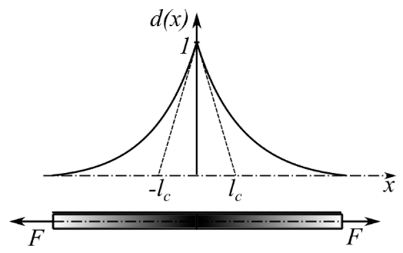
Griffith’s theory [9] has been a basis for a number of new damage and fracture mechanics theories for over a century. The fracture criterion is based on the equilibrium of the surface energy and the bulk energy stored in the material. It predicts crack initiation for existing cracks, but it does not feature crack nucleation and further crack propagation. At the end of the 20th century, Francfort and Marigo [24] introduced a variational fracture model based on minimizing an energy functional. That model was regularized in [25], by using a phase-field to determine damage in the material. The model was applied to an infinitely long bar with a constant cross-section by using the phase-field as a diffuse method and a scalar damage field variable, d , which is a quantitative measure of micro-cracks presence in a material. A sharp crack at the axial position x = 0 in the bar is described by a damage field variable d ( x ) , with the limiting values of d ( 0 ) = 1 for fully damaged material, d ( ± ) = 0 for the undamaged state.
For the diffusive crack topology shown in Figure 2, d ( x ) can be defined as an exponential function of the bar length x as [26]:
d ( x ) = e | x | l c
where l c is a characteristic length. The exponential function in Equation (1) is the solution of the homogeneous differential Equation [27]:
d ( x ) l c 2 d ( x ) = 0
This differential equation is the Euler equation of the variational principle [27]:
d = A r g { inf I ( d ) }
where the functional is:
I ( d ) = 1 2 V { d 2 + l c 2 d 2 } d V
with d V = Γ d x gives the functional I ( e | x | / l c ) = l c Γ l ( d ) . The functional Γ l ( d ) is then:
Γ l ( d ) = 1 l c I ( d ) = 1 2 l c V { d 2 + l c 2 d 2 } d V
The regularized crack functional for the multi-dimensional problems is:
Γ l ( d ) = V γ l ( d , d ) d V
where the isotropic crack surface density function per unit volume in the solid is [17,27]:
γ l ( d , d ) = d 2 2 l c + l c 2 | d | 2
and is the gradient operator.

2.1. Energy State Potential in a Damaged Solid

For a small strain theory or a logarithmic strain measure for large strains, an additive decomposition of total strain can be employed as ε = ε e + ε p , where ε is a total strain, ε e is an elastic strain, and ε p is a plastic strain. Internal potential energy density W int is expressed as sum of an elastic bulk energy W e , a plastic energy W p , and a fracture contribution W f r a c as [17]:
W int ( ε , ε p , ε ¯ P , d , d ) = W e ( ε ε p , d ) + W p ( ε ¯ p , d ) + W f r a c ( d , d )
where the elastic strain energy is:
W e ( ε ε p , d ) = ( 1 d ) 2 1 2 ε e T : C 0 : ε e = ( 1 d ) 2 1 2 σ 0 : ε e = ( 1 d ) 2 ω ¯ e
In Equation (9), C 0 is an elastic constitutive tensor, σ 0 is an effective Cauchy stress tensor, while ω ¯ e represents an effective elastic strain energy density per unit volume:
ω ¯ e = 1 2 σ 0 : ε e
The total plastic strain energy density is [17]:
W p ( ε ¯ p , d ) = ( 1 d ) 2 ω ¯ p
where an effective plastic strain energy density per unit volume ω ¯ p is a function of an effective plastic strain ε ¯ p , which includes both a bulk and a dissipation contribution [26,27,28]:
ω ¯ p ( ε ¯ p ) = ( σ y 0 , σ y v ) ( ε ¯ p + 1 n e n ε ¯ p ) + 1 2 H ε ¯ p 2 + σ y v ε ¯ p
where σ y v is an initial yield stress, σ y 0 , is a saturation hardening stress, n is a hardening exponent, and H is a hardening modulus.
For the fracture contribution, the work-densities-based criterion with threshold [17] is employed, because the damage does not occur immediately when the loading is applied in ductile materials. Equally, it is necessary to control the influence of elastic bulk energy density on the damage initiation and contribution from a critical effective total strain value ε ¯ c r . For that purpose, Miehe et al. [17] defined the fracture surface energy density as:
W f r a c ( d , d ) = G v [ d + l c 2 2 | d | 2 ]
where G v = G c / l c is a specific fracture energy per unit volume [26]. One can notice that damage d constitutes the linear term in Equation (13) [23]. The Equation (13) is further expressed in term of the regularized surface density function per unit volume in Equation (7), as follows:
W f r a c ( d , d ) = G v [ d + l c 2 2 | d | 2 ] = G v l c [ d l c + l c 2 | d | 2 ] = = G v l c [ d 2 2 l c + l c 2 | d | 2 ] + G v l c d l c G v l c d 2 2 l c = G v l c γ l ( d , d ) + G v 2 ( 2 d d 2 ) = = G v l c γ l ( d , d ) + G v 2 ( 1 ( 1 d ) 2 ) = G v l c γ l ( d , d ) + G v 2 ( 1 d ) 2 G v 2
Here, ω ¯ c r = G v / 2 is defined as threshold energy density value [17]. Finally, the total internal potential energy density, following Equations (8), (9), (11), and (14) is:
W int ( ε , ε p , ε ¯ P , d , d ) = ( 1 d ) 2 ( ω ¯ e + ω ¯ p ω ¯ c r ) + ω ¯ c r + G v l c γ l ( d , d )
or, in the expanded form:
W int ( ε , ε p , ε ¯ p , d , d ) = ( 1 d ) 2 1 2 σ 0 : ε e + ( 1 d ) 2 ( σ y 0 , σ y v ) ( ε ¯ p + 1 n e n ε ¯ p ) + ( 1 d ) 2 1 2 H ε ¯ p 2 + ( 1 d ) 2 σ y v ε ¯ p + G v l c γ l ( d , d ) + G v 2 ( 1 d ) 2 G v 2
The total internal energy potential can be calculated as:
Ψ = V W int   d V = V ( 1 d ) 2 ω ¯ e + ω ¯ p ω ¯ σ + ω ¯ σ + G v l c γ l ( d , d ) d V
The variation of the total internal energy potential over variables ε e , d , and ε ¯ p [26,27,28]
δ Ψ = V ( W int ε e : δ ε e + W int d : δ d + W int ε ¯ p : δ ε ¯ p ) d V
can be further expressed as
δ Ψ = V { σ : δ ε e + 1 2 g ( d ) ε e T : σ 0 δ d + g ( d ) ( σ y 0 , σ y v ) ( ε ¯ p + 1 n e n ε ¯ P ) δ d + + g ( d ) 1 2 H ε ¯ p 2 δ d + g ( d ) σ y v ε ¯ p δ d g ( d ) G V 2 + G V [ d δ d + l c 2 d δ d ] + + ( g ( d ) σ 0 : ε p ε ¯ p + g ( d ) ( σ y 0 , σ y v ) ( 1 e n ε ¯ p ) + g ( d ) H ε ¯ p + g ( d ) σ y v ) δ ε ¯ p } d V
where g ( d ) is a degradation function and its derivative g ( d ) over d [15,29]:
g ( d ) = ( 1 d ) 2
g ( d ) = 2 ( 1 d )
A variation of the external potential energy is [30]:
δ W e x t = V b δ u d V + A h δ u d A
where b is a body force field per unit volume, and h is a boundary traction per unit area, u is a displacement vector. Equilibrium of variation of internal and external potential energy δ Ψ = δ W e x t can be expressed as:
V { σ : δ ε e + 1 2 g ( d ) ε e T : σ 0 δ d + g ( d ) ( σ y 0 , σ y v ) ( ε ¯ p + 1 n e n ε ¯ p ) δ d + + g ( d ) 1 2 H ε ¯ p 2 δ d + g ( d ) σ y v ε ¯ p δ d g ( d ) G V 2 + G V [ d δ d + l c 2 d δ d ] + + ( g ( d ) σ 0 : ε p ε ¯ p + g ( d ) ( σ y 0 , σ y v ) ( 1 e n ε ¯ p ) + g ( d ) H ε ¯ p + g ( d ) σ y v ) δ ε ¯ p } d V = V b δ u d V + A h δ u d A
Making use of the Gauss theorem and total derivatives [26], the transformed form in Equation (23) is expressed as:
V { [ g ( d ) [ ω ¯ e + ω ¯ p G V 2 ] + G V [ d l c 2 2 d ] ] δ d [ D i v [ σ ] + b ] δ u + + ( g ( d ) σ 0 : ε p ε ¯ p + g ( d ) ( σ y 0 , σ y v ) ( 1 e n ε ¯ p ) + g ( d ) H ε ¯ p + g ( d ) σ y v ) δ ε ¯ p } d V + A { [ σ n h ] δ u } d A + A { [ G V l c 2 d n ] δ d } d A = 0
By applying the Neumann-type boundary conditions:
σ n h = 0
d n = 0
the equilibrium equation is [30]:
D i v [ σ ] + b = 0
the plasticity yield condition law [26]:
σ ¯ e q σ y v ( σ y 0 , σ y v ) ( 1 e n ε ¯ p ) H ε ¯ p = 0
and the phase-field damage evolution law is defined as [17]:
G V [ d l c 2 2 d ] + g ( d ) max ( ω ¯ e + ω ¯ p G v 2 ) = 0
The model described in the Equations (27)–(29) are implemented in the in-house software PAK-DAM v24 [22]. Update of the maximum internal potential energy density stored in the material, ω ¯ e + ω ¯ p G v / 2 at the end of the time step is determined as:
  t + Δ t ω ¯ = { ω ¯ e + ω ¯ p G v 2 ; ω ¯ e + ω ¯ p G v 2 >   t ω ¯   t ω ¯ ; otherwise
where t is the time at the beginning of time step, Δ t is the time increment.

2.2. A Critical Total Strain vs. Threshold Value of Fracture Energy

For determination of the critical strain energy density per unit volume for failure ω ¯ c r , the principle assumption from Equation (30) is that threshold value of fracture energy is G v / 2 . This strain energy density cannot be dissipated on damaging of the material, and this is represented by the hatched area in Figure 3, which is based on one-dimensional homogeneous model problem [17]. It can be calculated as the relationship between the effective elastic strain energy density determined for the effective critical strain value ε ¯ c r , and the elastic strain energy density for difference between ε ¯ c r and a yield strain ε ¯ y as:
ω ¯ c r = 1 2 E ( ε ¯ c r 2 ( ε ¯ c r ε ¯ y ) 2 )
where a yield strain is determined as ε ¯ y = σ ¯ y / E and E represented Young’s modulus as a linear relationship between stress and strain E = tg α (Figure 3).
From Equation (31), the critical fracture energy per unit volume can be calculated as [17]:
G v = E ε ¯ c r 2 ε ¯ c r σ ¯ y E 2
Consequently, a critical value of total strain ε ¯ c r can be defined from the stress–strain diagram obtained in the experiments; and with the known Young’s modulus and the yield stress, the critical fracture energy release rate per unit volume can be determined as internal material parameter by Equation (32).

2.3. Experimental Investigation of Metallic CT Specimens

Microstructural transformation can typically be induced by temperature or by deformation. It is well reported in the literature that transformation occurs during tensile testing. In this investigation, metastable austenite AISI 316L stainless steel specimens were tested. This material exhibits microstructural transformation from austenite to martensite during the plastic yielding. The transformation occurs at a temperature which depends on the chemical composition, for which empirical equations are given in [31]. The empirical equations for determining the temperature for the initiation of microstructural transformation are given in [32]. The experimental part of the research concerns the growth of a crack in a thin CT specimen, during loading at a constant loading rate. In the case of metastable austenite, a microstructural transformation into a martensite microstructure occurs at 0.05% of permanent deformation, as reported in [33]. From the crystallographic perspective, the transformation occurs from a face-centered cubic austenite structure to a body-centered tetragonal martensite crystal structure. Such transformations provide a higher ratio between ultimate tensile strength σ u and yield stress σ y . The uniaxial tensile tests were carried out by ASTM E8/E8M standard [34] with the four flat specimens (thickness t = 3   mm ). The average identified material parameters for Young’s modulus, Poisson’s coefficient, yield stress, ultimate tensile strength, and rotation factor are listed in Table 1. The obtained values are in the expected range, as they are also in the expected limits in the literature [35].
Fracture toughness experimental characterization was performed using the CT specimen following the ASTM E1820 standard [7]. The tests were performed at a room temperature of +24.5 °C and 54% humidity in displacement control rate 1 mm/min. During the tests, the force F and the CMOD were recorded. The data acquisition frequency during quasi-static testing was 10 Hz. The standard defines the basic procedure, which uses the load-displacement diagram to assess a single value such as the stress intensity factor K I , the J-integral J I , or Crack-Tip Opening Displacement (CTOD) δ . The optical measurement of the fracture surface done by stereo microscope OLYMPUS SZX12 (Tokyo, Japan) was employed to determine the initial and final crack lengths accurately. One or more specimens can be used to evaluate the J-integral at crack initiation, J I or CTOD, δ .
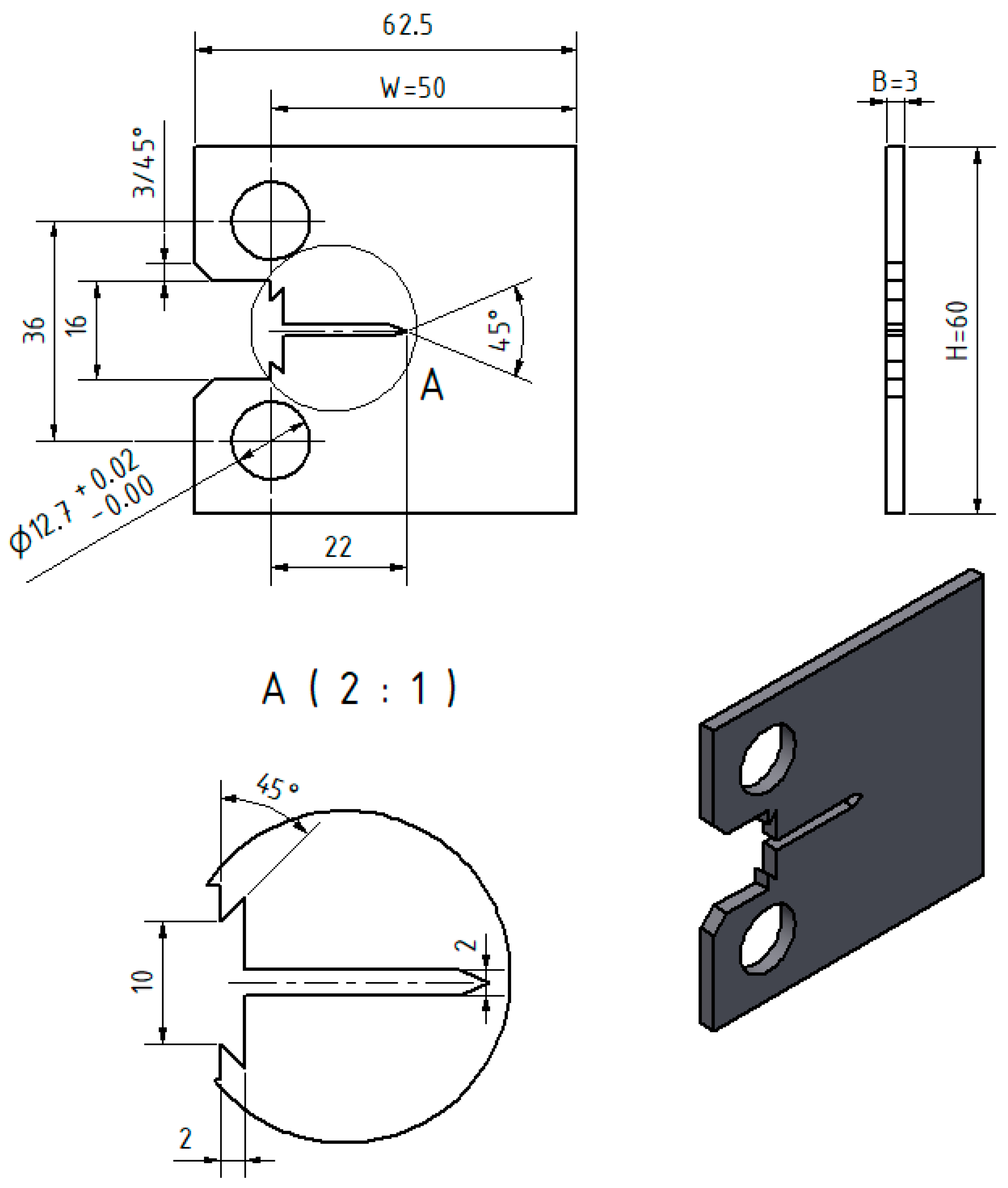
The ASTM E1820 [7] standard includes a δ R resistance curve procedure for CTOD determination, similar to the J-integral evaluation. The stress intensity factor K I is calculated using the current crack length. When the material exhibits ductile crack growth, the above procedure may be used to obtain the δ R curve. For this purpose, the CT specimen (Figure 4) was subjected to fatigue loading to get a fatigue pre-crack according to standard ASTM E1820 [7]. The maximum fatigue loading force ensures that the plastic zone size at the crack tip is sufficiently small not to influence the measured fracture toughness result. Equally, a loading below the proposed maximum was not suitable, as it would require considerable time to run to the required crack growth/states.
For CTOD determination, the whole crack length (machined notch and fatigue crack) should be between 0.45 and 0.70 W (W is the specimen length). In this experiment, the initial crack length was 25.35 mm (0.507 W). Fracture testing was performed with a stroke control of 1 mm/min at room temperature.
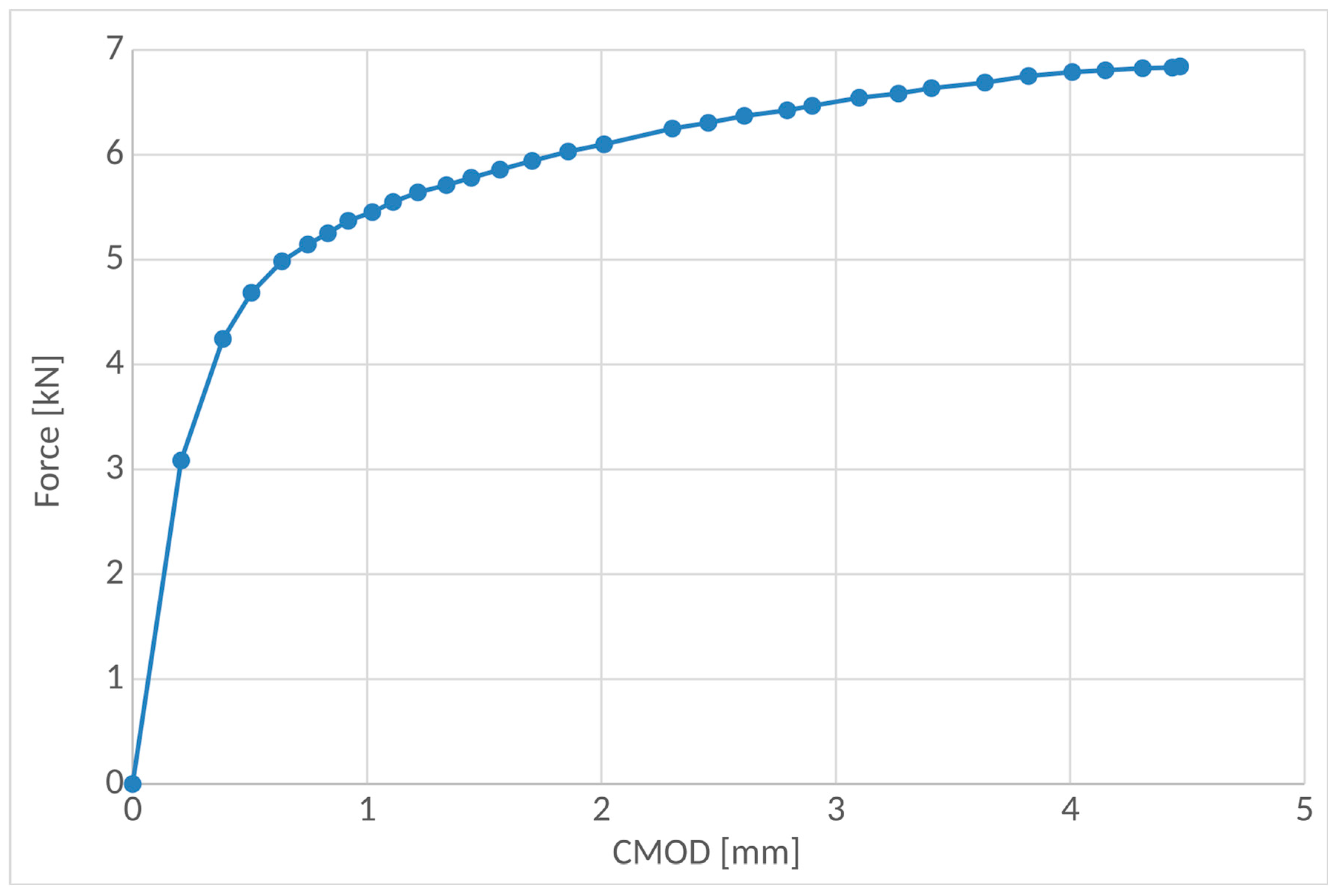
During testing, the Force (F) vs. Crack-Mouth Opening Displacement (CMOD) curve was recorded, as shown in Figure 5. After testing, the initial crack length and the final crack extension were measured according to standard ASTM E1820 [7]. The measured values are listed in Table 2.
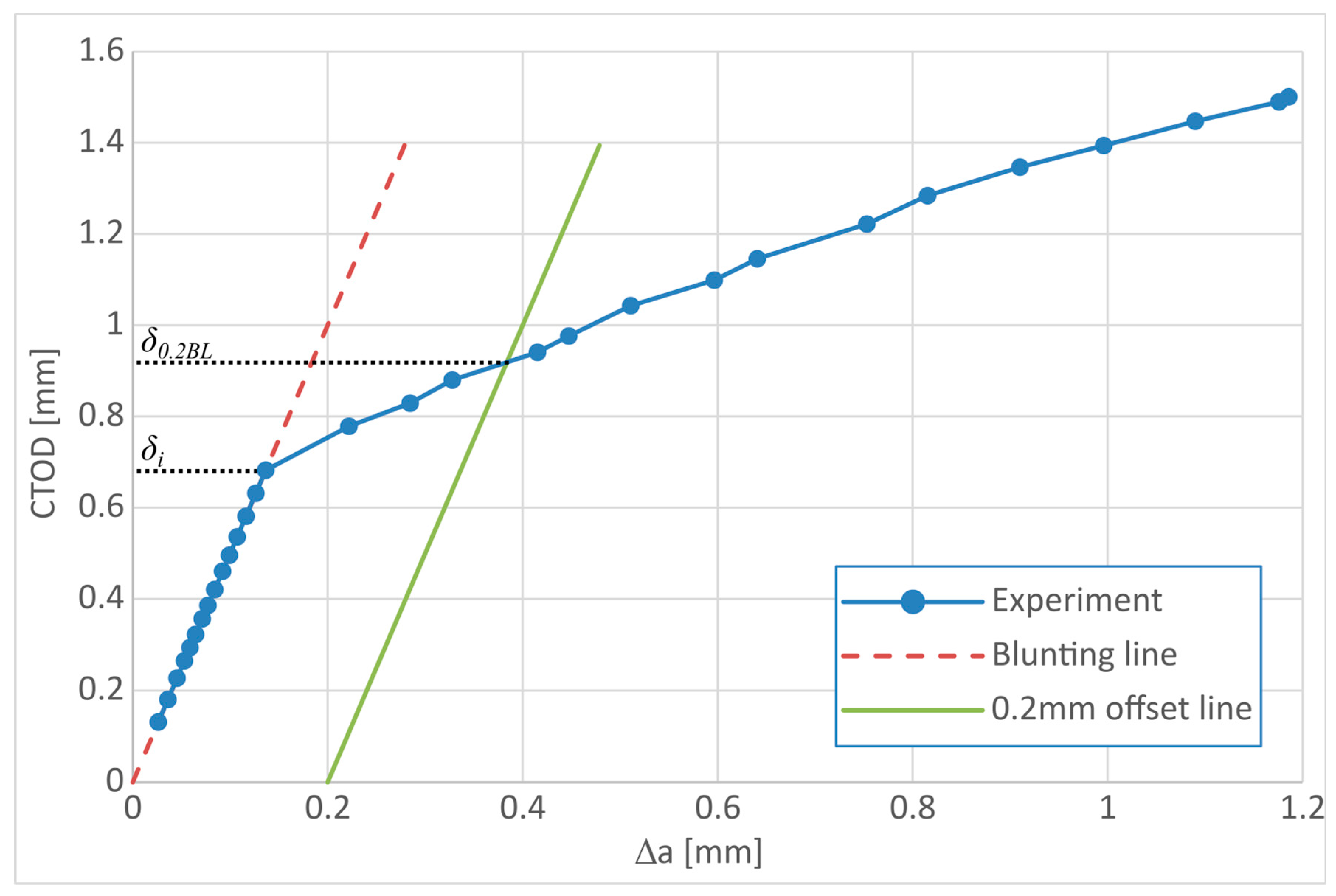
According to standard ASTM E1820 [7], the CTOD values were calculated by taking into account the CMOD measured values in the recorded F-CMOD diagram (Figure 5). The CTOD–R curve is derived by using the values of crack growth acquired with the normalization method and the equations for CTOD. The CTOD can be used as a fracture parameter related to crack growth for the CT specimens. The relationship between CMOD and CTOD is described in standard ASTM E1290 [36] and in Kudari and Kodancha [37] as:
C T O D = K I 2 m σ y E * + C M O D r ( W a ) a + r ( W a )
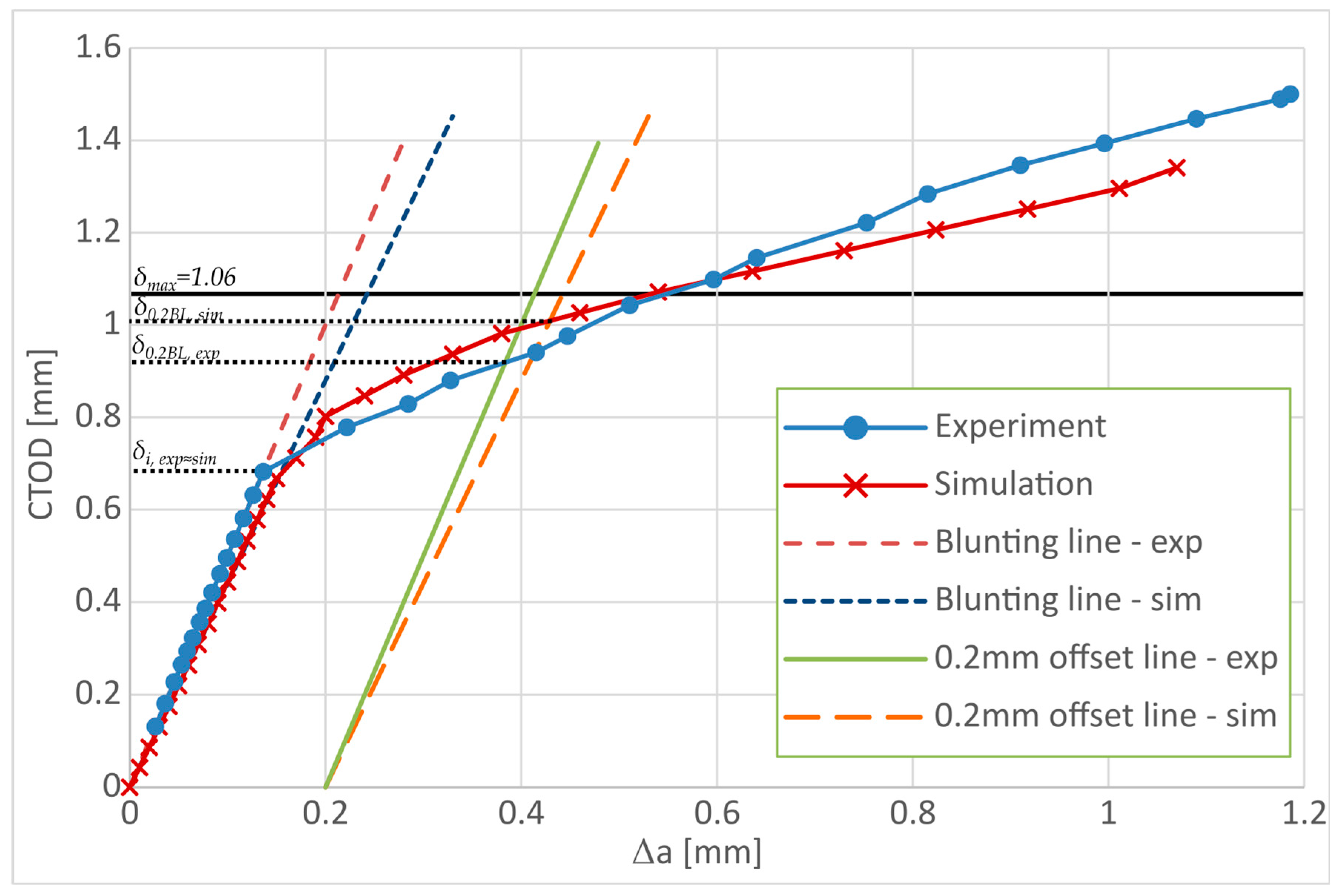
where r is the rotation factor, a is the crack length, W is the length of the specimen, K I is the stress intensity factor in the elastic loading range, σ y is the yield stress, m = 1 for the plain stress and m = 2 for the plain strain, E * is the modulus of elasticity for plane stress E * = E , and for the plain strain E * = E / ( 1 ν ) 2 , and ν is the Poisson’s coefficient. Based on the Equation (33), the points on CTOD– Δ a curve (CTOD–R resistance curve), where Δ a is the crack extension, were calculated and plotted as in Figure 6. However, in Equation (33), only the plastic part (the second term) was considered, because the elastic part of CTOD was insignificant and was neglected. In Figure 6, the blunting construction line (red dashed line) was defined with the slope k 1 = 5 . To determine a value of CTOD, for δ 0.2 B L , it is necessary to draw a line parallel to the blunting line at an offset value of 0.2 mm:
δ 0.2 B L ( Δ a ) = k 1 ( Δ a 0.2 ) .
The CTOD for δ 0.2 B L was equal to 0.92.

3. PFDM Simulation of Ductile Fracture

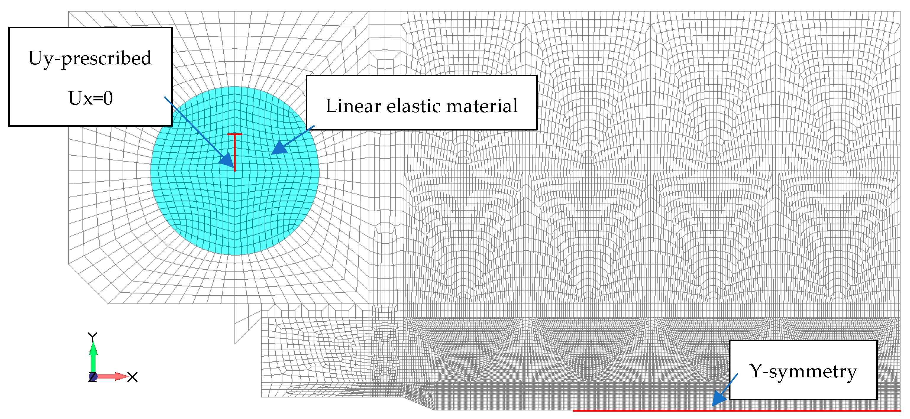
The experiment with the CT specimen described in the previous section was simulated in PAK-DAM [22], with the PFDM described in Section 2. Due to the symmetry of the test, one half of the specimen was modeled, with appropriate boundary conditions, see Figure 7. The Finite Element mesh consists of 24,952 linear quadrilateral two-dimensional plane stress elements (Figure 7). The size of the element in the cracking zone is 0.086 mm. Loading was applied as a prescribed displacement of a reference point at the center of the pin in Y direction. The pin was modeled as a linear elastic material.
The material parameters used for the simulations were obtained from the experiments and are given in Table 1. The parameters of the PFDM model are given in Table 3.
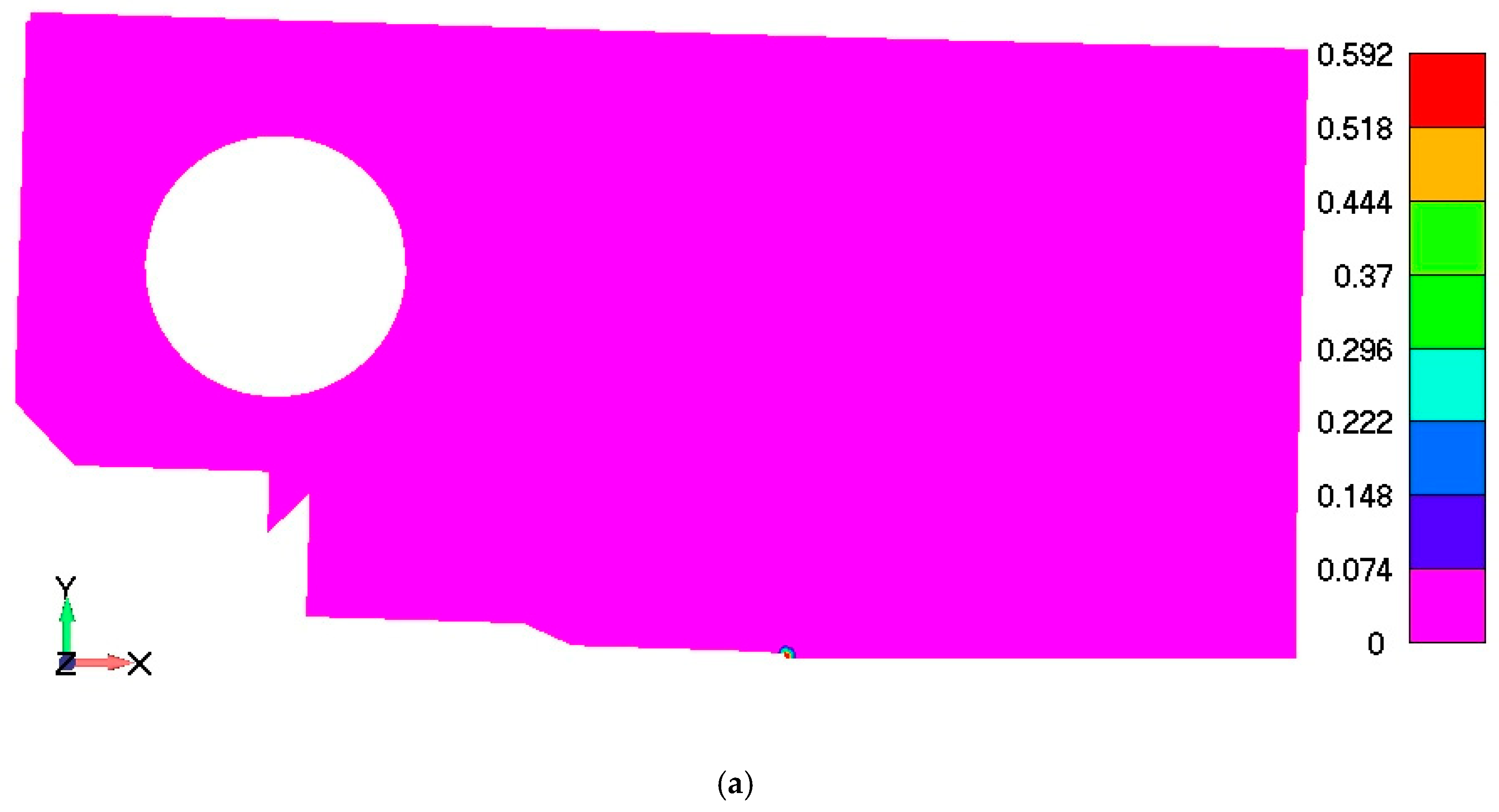
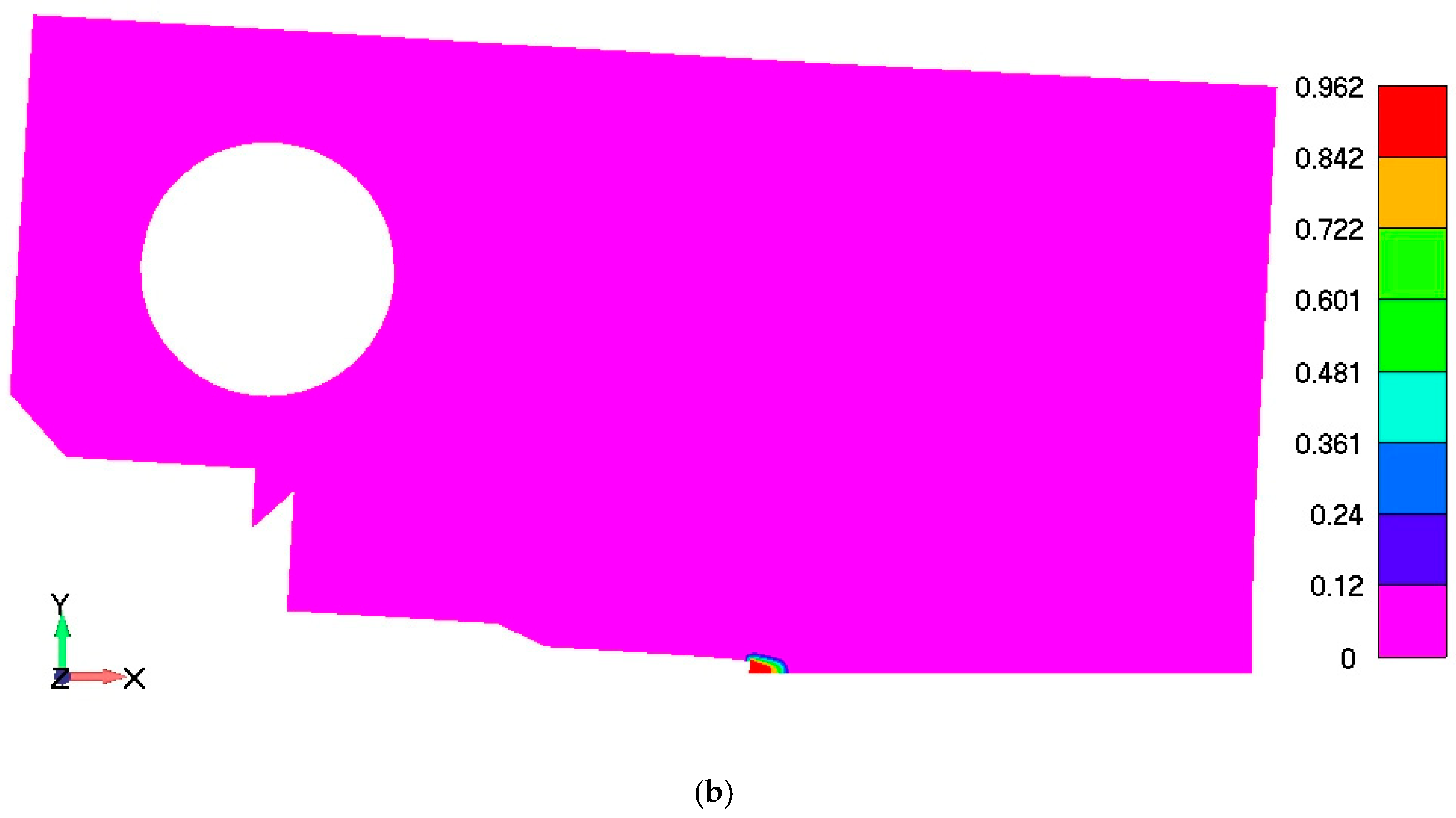
Damage initiated at the crack tip and evolved from zero up to the values which can be considered total failure, i.e., d exceeding 0.9 (Figure 8a,b). The x length of the completely failed/damaged zone was taken as the crack length for the specific state of loading, i.e., CMOD. Simulation results for distribution of damage within the CT specimen for the total CMOD of 2.2377 mm are shown in Figure 8b, which corresponds to the end of the diagram shown in Figure 6.
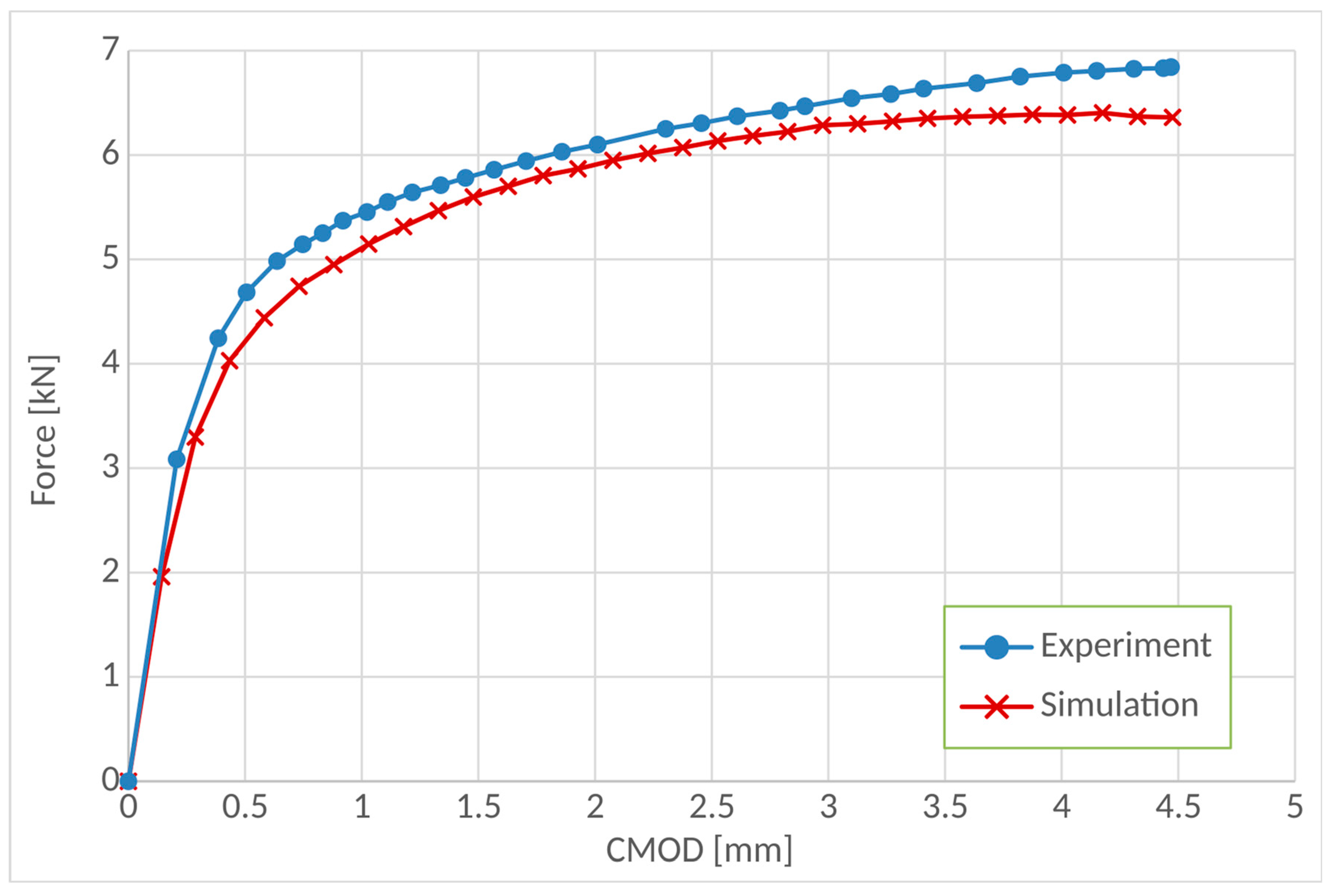
Comparison of F–CMOD diagrams obtained in the experiment and in the PFDM simulation is given in Figure 9, where a very good agreement can be observed. The simulation results are within 8% of the experimental results.
The simulation results for the CTOD were calculated by using Equation (33), where CMOD was measured for each step as the length of the damage zone. Comparison of the experimental and simulation results for CTOD Δ a diagram is shown in Figure 10. The results demonstrate very good capability of the proposed PFDM implementation for simulation of ductile damage in CT specimens. The maximal values of CTOD max = δ max = 1.06   mm and Δ a max = 6.07   mm are determined according to ASTM E1820 standard in Section A10.3 [7] and the limit line is also shown in Figure 10. Based on these results, the CTOD value for both the simulation and the experiment is obviously at the upper limit of ductile fracture behavior of the tested AISI 316L steel.
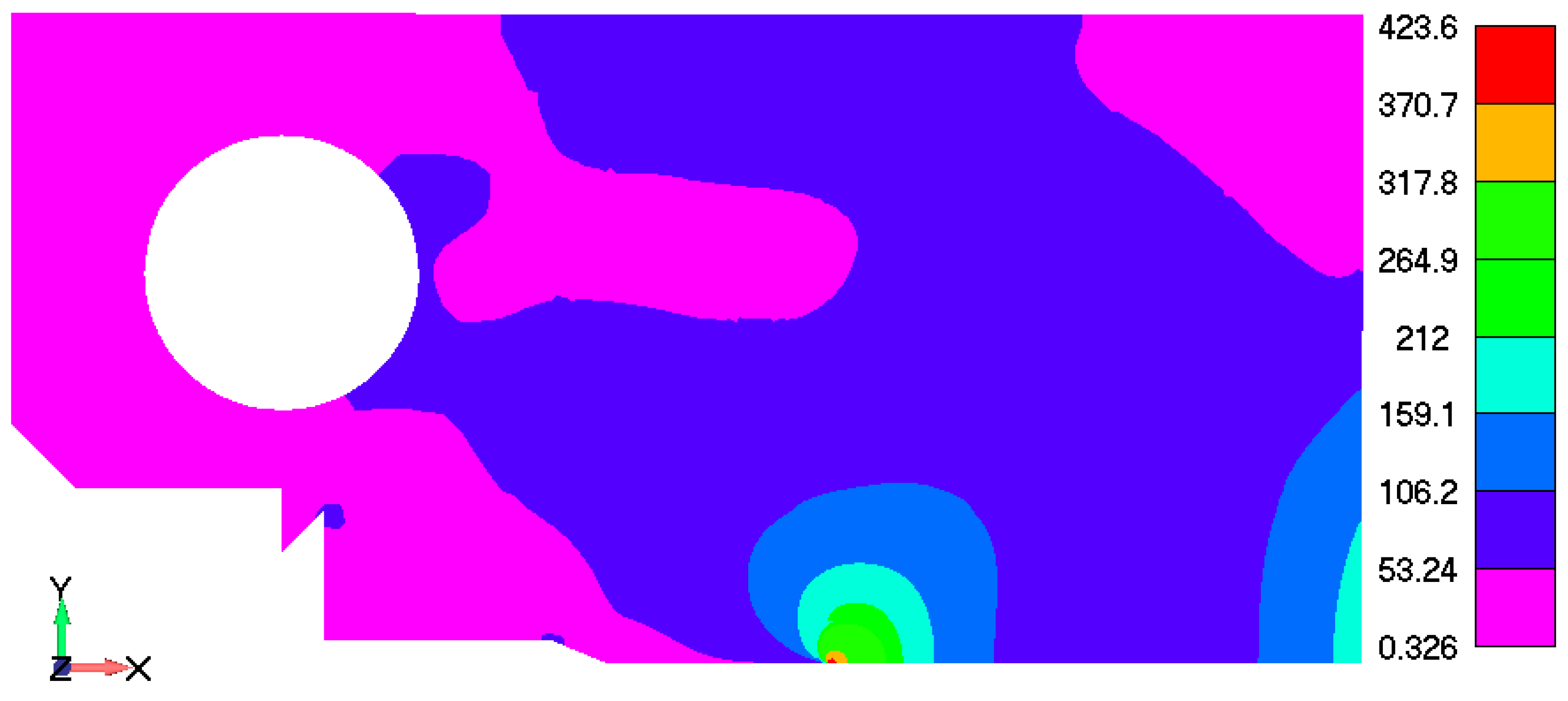
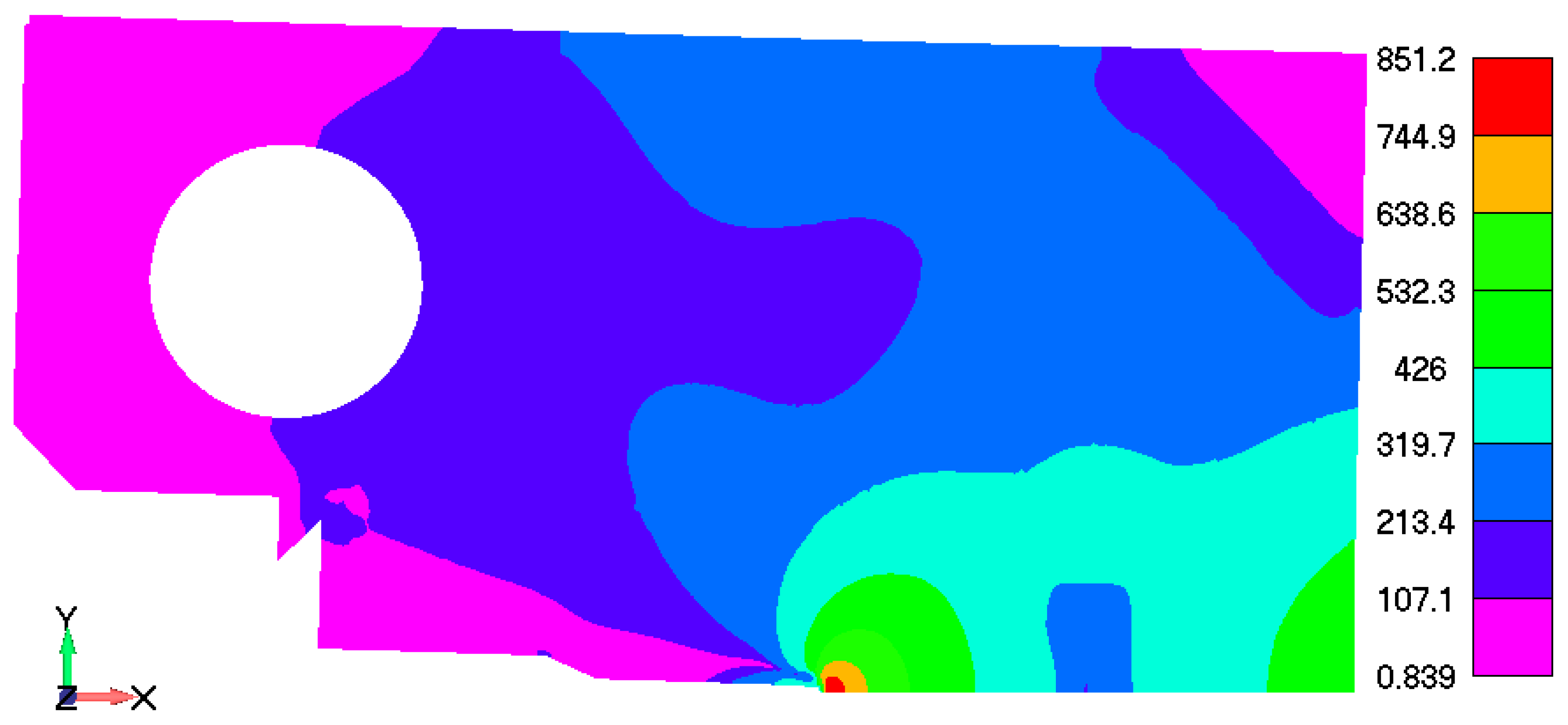
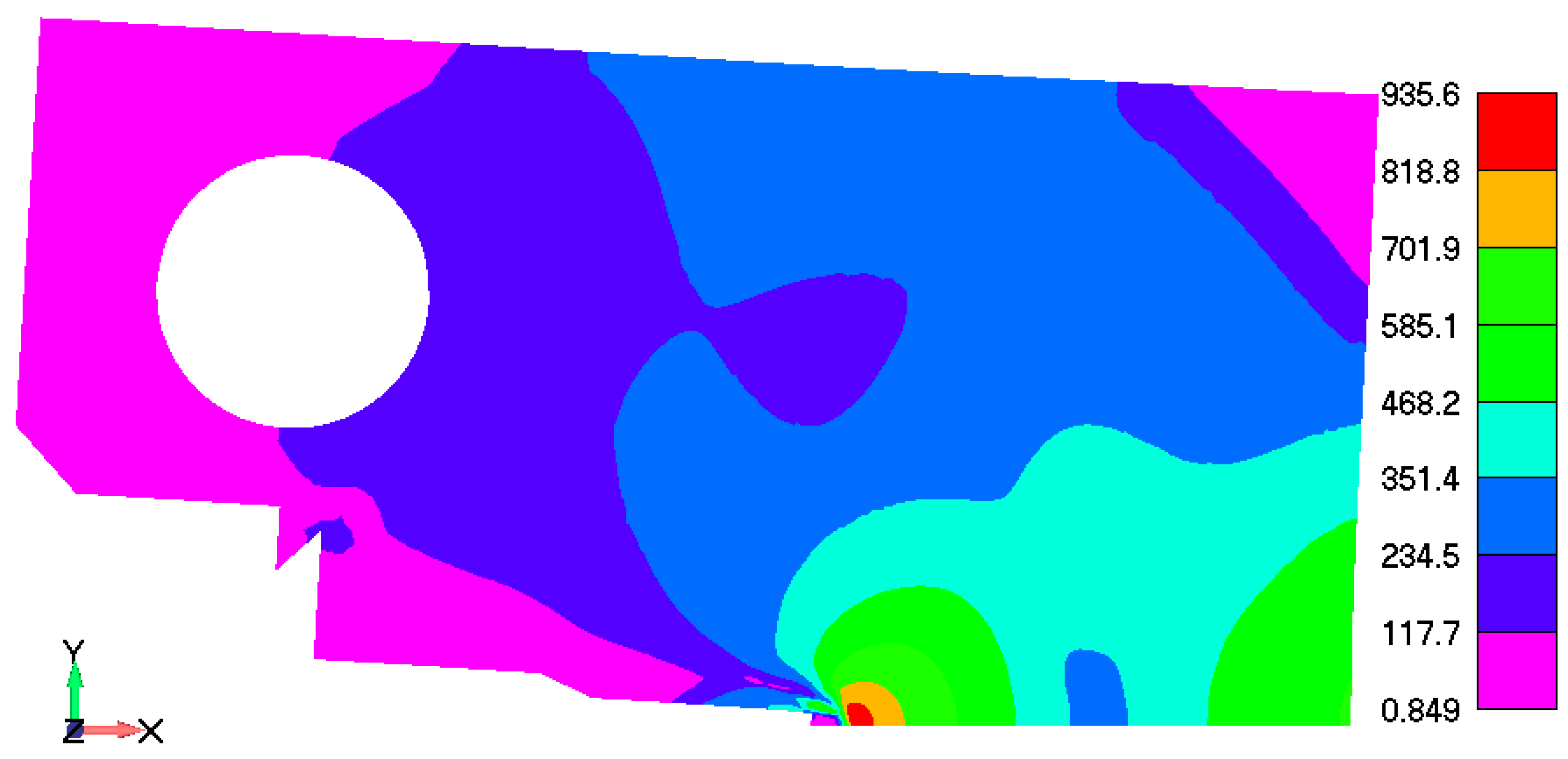
Equivalent von Mises stress distribution at three characteristic loading stages is shown form Figure 11, Figure 12 and Figure 13. The first state in Figure 11 corresponds to the elastic response, without any damage; the second shown in Figure 12, when the maximum damage in narrow zone near the initial crack tip is 0.592 (time step 15) (Figure 8a), at the final (30th) time step shown in Figure 13, which corresponds to the damage field in Figure 8b. One can observe that stress increases in the crack-tip zone, leading to the damage evolution up to the maximum, which corresponds to the total failure and fracture; at which stage, the stress and load-bearing capacity drops to zero.

4. Conclusions

The PFDM was implemented into the in-house developed FEM code PAK-DAM [22] and used for simulation of standard (plane stress) fracture test of the ductile steel AISI 316L. For this purpose, the PFDM for ductile fracture used the work-densities-based criterion with threshold [17], where damage onset was determined by the critical value of total strain. Critical fracture energy was calculated as an internal parameter. All the material parameters were obtained from the experimental curves, obtained in the standard characterization test, whilst the PFDM analysis parameters were obtained by calibration of the results at the continuum scale.
Experimental results were obtained in terms of standard outputs CTOD–R curve and F–CMOD curve, and directly compared to the PFDM simulation results. Experimentally obtained CTOD initiation, δ i , exp and the value obtained in the simulation δ i , s i m are equivalent. The slope of the blunting line recorded by experimental investigation is higher than the slope of the blunting line obtained in the simulation. The CTOD is overestimated in the simulations up to the crack length equal to 0.6, after which the simulation results underestimate the CTOD. The maximum discrepancy between the curves is 8%. By increasing the damage value, the equivalent stress decreases due to the decreased stiffness of damaged material. These observations are in line with the experimental observation of the crack propagation; so overall, the results obtained by the implemented PFDM model show quite good agreement with experimentally obtained results.

Author Contributions

Conceptualization, V.D. and N.G.; formal analysis, N.G., V.M. and N.D.; investigation, V.D., N.G. and V.M.; methodology, V.D. and N.G.; software, V.D. and M.Ž.; supervision, M.Ž. and N.D.; validation, V.D., N.G. and D.J.; visualization, V.D. and N.G.; writing—original draft, V.D. and N.G.; writing—review and editing, M.Ž., V.M., D.J. and N.D. All authors have read and agreed to the published version of the manuscript.

Funding

This research was supported by the Science Fund of the Republic of Serbia, #GRANT No 7475, Prediction of damage evolution in engineering structures—PROMINENT and the Slovenian Research Agency ARIS for the research program P2-0137 Numerical and Experimental analysis of Nonlinear Mechanical Systems.

Data Availability Statement

The original contributions presented in the study are included in the article material, further inquiries can be directed to the corresponding author.

Conflicts of Interest

The authors declare no conflicts of interest. The funders had no role in the design of the study; in the collection, analyses, or interpretation of data; in the writing of the manuscript; or in the decision to publish the results.

References

  1. Zhu, X.-K.; Joyce, J.A. Review of fracture toughness (G, K, J, CTOD, CTOA) testing and standardization. Eng. Fract. Mech. 2012, 85, 1–46. [Google Scholar] [CrossRef]
  2. Garcia-Gonzalez, A.; Aguilera, J.A.; Cerezo, P.M.; Castro-Egler, C.; Lopez-Crespo, P. A Literature Review of Incorporating Crack Tip Plasticity into Fatigue Crack Growth Models. Materials 2023, 16, 7603. [Google Scholar] [CrossRef] [PubMed]
  3. Ajmal, M.; Lopez-Crespo, C.; Cruces, A.S.; Lopez-Crespo, P. New Plastic Crack-Tip Opening Displacement Tool Based on Digital Image Correlation for Estimating the Fatigue-Crack-Growth Law on 316L Stainless Steel. Materials 2023, 16, 4589. [Google Scholar] [CrossRef] [PubMed]
  4. Khor, W.L. Crack Tip Opening Displacement (CTOD) in Single Edge Notched Bend (SEN(B)). Ph.D. Thesis, Brunel University, London, UK, 2018. [Google Scholar]
  5. BS 7448-1:1991; Fracture Mechanics Toughness Tests—Part 1: Method for Determination of KIc, Critical CTOD and Critical J Values of Metallic Materials. BSI: London, UK, 2007.
  6. ISO 12135-2016; Metallic Materials—Unified Method of Test for the Determination of Quasistatic Fracture Toughness. ISO: Geneva, Switzerland, 2016.
  7. ASTM E1820 Standard; Standard Test Method for Measurement of Fracture Toughness. American Society for Testing and Materials: Philadelphia, PA, USA, 2019.
  8. WES 1108:2016; Standard test method for Crack-Tip Opening Displacement (CTOD) fracture toughness measurement. The Japan Welding Engineering Society: Tokyo, Japan, 1995.
  9. Griffith, A.A., VI. The phenomena of rupture and flow in solids. Philos. Trans. R. Soc. Lond. A 1921, 221, 163–198. [Google Scholar] [CrossRef]
  10. Seleš, K.; Tomić, Z.; Tonković, Z.; Gubeljak, N. Validation of the Phase-Field Model for Brittle Fracture. Procedia Struct. Integr. 2022, 42, 1721–1727. [Google Scholar] [CrossRef]
  11. Seleš, K.; Aldakheel, F.; Tonković, Z.; Sorić, J.; Wriggers, P. A general phase-field model for fatigue failure in brittle and ductile solids. Comput. Mech. 2021, 67, 1431–1452. [Google Scholar] [CrossRef]
  12. Khandelwal, N.; Ramachandra Murthy, A. Ductile fracture simulation using phase field method with various damage models based on different degradation and geometric crack functions. Mater. Today Commun. 2023, 35, 105627. [Google Scholar] [CrossRef]
  13. Yin, B.; Kaliske, M. A ductile phase-field model based on degrading the fracture toughness: Theory and implementation at small strain. Comput. Methods Appl. Mech. Eng. 2020, 366, 113068. [Google Scholar] [CrossRef]
  14. Eldahshan, H.; Bouchard, P.-O.; Alves, J.; Perchat, E.; Muñoz, D.P. Phase field modeling of ductile fracture at large plastic strains using adaptive isotropic remeshing. Comput. Mech. 2021, 67, 763–783. [Google Scholar] [CrossRef]
  15. Ambati, M.; Gerasimov, T.; De Lorenzis, L. Phase-field modeling of ductile fracture. Comput. Mech. 2015, 55, 1017–1040. [Google Scholar] [CrossRef]
  16. Ambati, M.; Kruse, R.; De Lorenzis, L. A phase-field model for ductile fracture at finite strains and its experimental verification. Comput. Mech. 2016, 57, 149–167. [Google Scholar] [CrossRef]
  17. Miehe, C.; Hofacker, M.; Schänzel, L.-M.; Aldakheel, F. Phase field modeling of fracture in multi-physics problems. Part II. Coupled brittle-to-ductile failure criteria and crack propagation in thermo-elastic–plastic solids. Comput. Methods Appl. Mech. Eng. 2015, 294, 486–522. [Google Scholar] [CrossRef]
  18. Huang, C.; Gao, X. Development of a phase field method for modeling brittle and ductile fracture. Comput. Mater. Sci. 2019, 169, 109089. [Google Scholar] [CrossRef]
  19. Lesičar, T.; Polančec, T.; Tonković, Z. Convergence Check Phase-Field Scheme for Modelling of Brittle and Ductile Fractures. Appl. Sci. 2023, 13, 7776. [Google Scholar] [CrossRef]
  20. Liu, S.; Han, F.; Deng, X.; Lin, Y. Thermomechanical Peridynamic Modeling for Ductile Fracture. Materials 2023, 16, 4074. [Google Scholar] [CrossRef] [PubMed]
  21. Chen, C.-J.; Su, M.-N.; Wang, Y.-H.; Zhu, R.-H. Experimental and numerical investigations of crack growth of hot-rolled steel Q420C using cohesive zone model. Theor. Appl. Fract. Mech. 2023, 127, 104036. [Google Scholar] [CrossRef]
  22. Živković, M.; Dunić, V.; Rakić, D.; Grujović, N.; Slavković, R.; Kojić, M. PAK-DAM Software for Damage and Fracture Simulation; Faculty of Engineering, University of Kragujevac: Kragujevac, Serbia, 2024. [Google Scholar]
  23. Miehe, C. A multi-field incremental variational framework for gradient-extended standard dissipative solids. J. Mech. Phys. Solids 2011, 59, 898–923. [Google Scholar] [CrossRef]
  24. Francfort, G.; Marigo, J.-J. Revisiting brittle fracture as an energy minimization problem. J. Mech. Phys. Solids 1998, 46, 1319–1342. [Google Scholar] [CrossRef]
  25. Bourdin, B.; Francfort, G.A.; Marigo, J.-J. Numerical experiments in revisited brittle fracture. J. Mech. Phys. Solids 2000, 48, 797–826. [Google Scholar] [CrossRef]
  26. Živković, J.; Dunić, V.; Milovanović, V.; Pavlović, A.; Živković, M. A Modified Phase-Field Damage Model for Metal Plasticity at Finite Strains: Numerical Development and Experimental Validation. Metals 2021, 11, 47. [Google Scholar] [CrossRef]
  27. Miehe, C.; Welschinger, F.; Hofacker, M. Thermodynamically consistent phase-field models of fracture: Variational principles and multi-field FE implementations. Int. J. Numer. Methods Eng. 2010, 83, 1273–1311. [Google Scholar] [CrossRef]
  28. Dunić, V.; Živković, J.; Milovanović, V.; Pavlović, A.; Radovanović, A.; Živković, M. Two-Intervals Hardening Function in a Phase-Field Damage Model for the Simulation of Aluminum Alloy Ductile Behavior. Metals 2021, 11, 1685. [Google Scholar] [CrossRef]
  29. Ambati, M.; Gerasimov, T.; De Lorenzis, L. A review on phase-field models of brittle fracture and a new fast hybrid formulation. Comput. Mech. 2015, 55, 383–405. [Google Scholar] [CrossRef]
  30. Kojić, M.; Bathe, K.J. Inelastic Analysis of Solids and Structures; Springer: Berlin/Heidelberg, Germany, 2005. [Google Scholar]
  31. Das, A.; Chakraborti, P.C.; Tarafder, S.; Bhadeshia, H.K.D.H. Analysis of deformation induced martensitic transformation in stainless steels. Mater. Sci. Technol. 2011, 27, 366–370. [Google Scholar] [CrossRef]
  32. Solomon, N.; Solomon, I. Deformation induced martensite in AISI 316 stainless steel. Rev. Metal. 2010, 46, 121–128. [Google Scholar] [CrossRef]
  33. Jagarinec, D.; Kirbiš, P.; Predan, J.; Vuherer, T.; Gubeljak, N. Analysis of deformation induced martensite in AISI 316L stainless steel. Mater. Test. 2016, 58, 547–552. [Google Scholar] [CrossRef]
  34. ASTM E8/E8M Standard; Standard Test Methods for Tension Testing of Metallic Materials. American Society for Testing and Materials: Philadelphia, PA, USA, 2015.
  35. Haneef, T.; Lahiri, B.B.; Bagavathiappan, S.; Mukhopadhyay, C.K.; Philip, J.; Rao, B.P.C.; Jayakumar, T. Study of the tensile behavior of AISI type 316 stainless steel using acoustic emission and infrared thermography techniques. J. Mater. Res. Technol. 2015, 4, 241–253. [Google Scholar] [CrossRef]
  36. ASTM E1290 Standard; Standard Test Method for Crack-Tip Opening Displacement (CTOD) Fracture Toughness Measurement. American Society for Testing and Materials: Philadelphia, PA, USA, 2017.
  37. Kudari, S.K.; Kodancha, K. On the relationship between J-integral and CTOD for CT and SENB specimens. Frat. Integrita. Strut. 2013, 2, 3–10. [Google Scholar] [CrossRef]
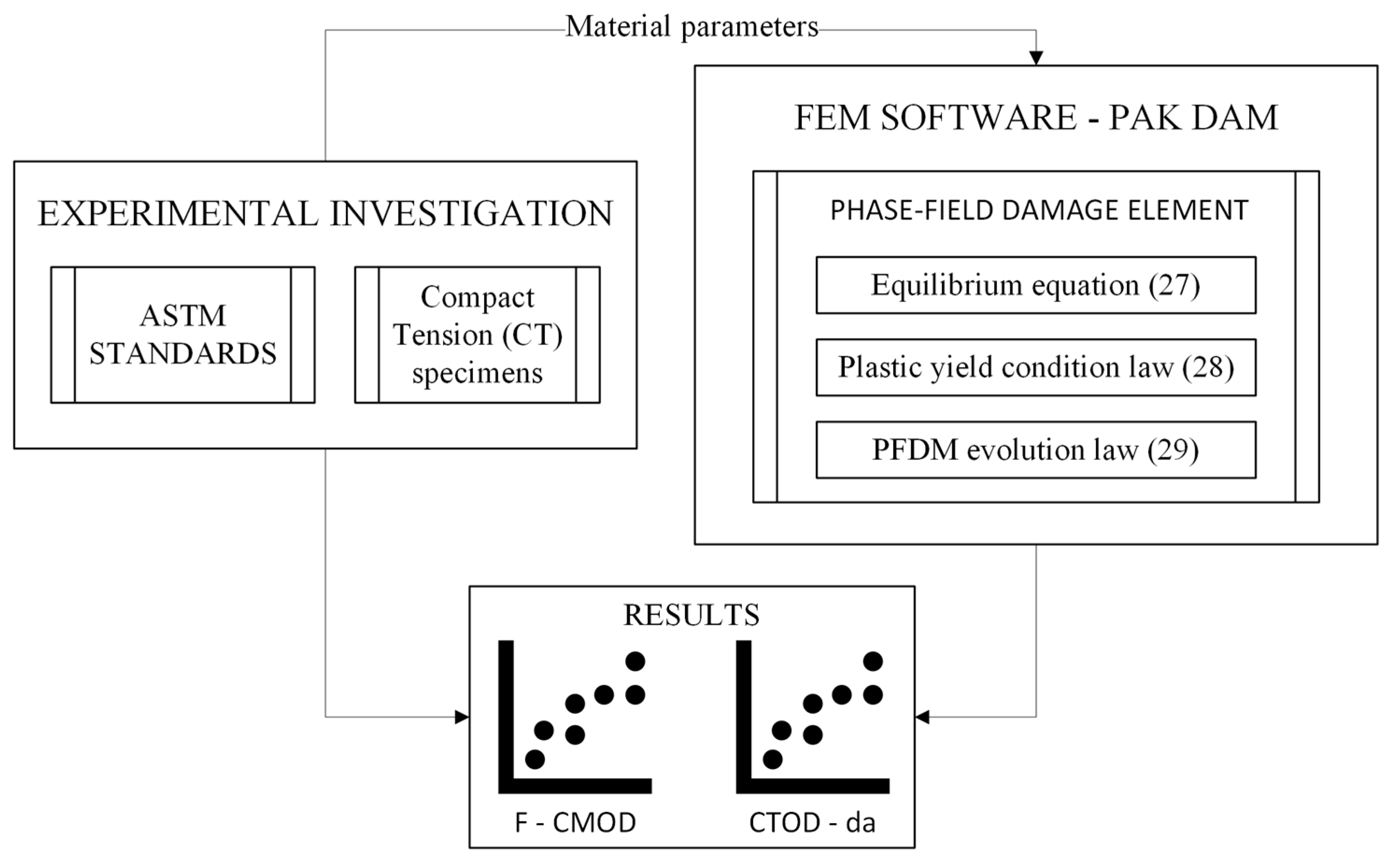
Figure 1. A flowchart of an experimental and PFDM-based simulation program.
Metals 14 00787 g001
Figure 2. A bar loaded by forces F on both sides: damage phase-field for diffusive crack topology. Adapted from Ref. [26].
Metals 14 00787 g002
Figure 3. Relationship between the threshold fracture energy value and the effective critical strain value.
Metals 14 00787 g003
Figure 4. Geometry and dimensions (in mm) of the CT specimen.
Metals 14 00787 g004
Figure 5. Force vs. Crack-Mouth Opening Displacement (experimental testing).
Metals 14 00787 g005
Figure 6. Crack-tip opening displacement vs. crack growth (experimental testing).
Metals 14 00787 g006
Figure 7. Finite Element mesh of half of the CT specimen model with boundary and loading conditions.
Metals 14 00787 g007
Figure 8. Damage field distribution obtained by PFDM simulations: (a) in the middle of loading range (15th step); (b) at the end of loading range (30th step).
Metals 14 00787 g008aMetals 14 00787 g008b
Figure 9. Comparison of F–CMOD diagram for experiment and simulation.
Metals 14 00787 g009
Figure 10. Crack-tip opening displacement vs. crack growth from the experiment and simulation results.
Metals 14 00787 g010
Figure 11. Equivalent stress in MPa at the initial step (1st step).
Metals 14 00787 g011
Figure 12. Equivalent stress in MPa in the middle of loading (15th step).
Metals 14 00787 g012
Figure 13. Equivalent stress in MPa at the end of loading (30th step).
Metals 14 00787 g013
Table 1. Mechanical properties obtained in uniaxial tensile test according to ASTM E8/E8m standard.
Material ParameterAverage Value
Young s   modulus   E [ MPa ] 188,000
Poisson s   coefficient   ν [ ] 0.33
Yield   stress   σ y [ MPa ] 280
Ultimate   tensile   strength   σ u [ MPa ] 575
Rotation factor according to standard ASTM E-1820 r [ ] 0.44
Table 2. Crack dimensions before and after testing.
Material ParameterValue
Initial   crack   length   a 0   [ mm ] 25.35
Finial   crack   length   a f   [ mm ] 26.40
Crack   length   growth   Δ a   [ mm ] 1.05
Table 3. Calibrated material parameters for PFDM simulation.
Material ParameterValue
Linear   hardening   H   [ MPa ] 1200
Characteristic   length   l c   [ mm ] 0.1
Critical   strain   value   ε ¯ c r   [ ] 1.0
Disclaimer/Publisher’s Note: The statements, opinions and data contained in all publications are solely those of the individual author(s) and contributor(s) and not of MDPI and/or the editor(s). MDPI and/or the editor(s) disclaim responsibility for any injury to people or property resulting from any ideas, methods, instructions or products referred to in the content.