Article

Ductile-to-Brittle Transition of Steel Due to Dynamic Loading

by
Gianmario Riganti
and
Ezio Cadoni
*
DynaMat SUPSI Laboratory, University of Applied Sciences and Arts of Southern Switzerland, 6850 Mendrisio, Switzerland
*
Author to whom correspondence should be addressed.
Metals 2024, 14(7), 807; https://doi.org/10.3390/met14070807
Submission received: 31 May 2024 / Revised: 7 July 2024 / Accepted: 8 July 2024 / Published: 11 July 2024

Abstract

:
The transition from ductile to brittle for metals is usually encountered during fast machining operations, in low-temperature environments, and in all situations involving very high strain rates. Traditionally, classical material models used in the dynamic structural analysis focus on the plastic-stress-versus-strain rate. As a result, those models cannot incorporate sudden changes in failure strains and strengths triggered by material behavior transition. The ability to predict realistically the dynamic behavior of structures based on physical constitutive equations depends on having a comprehensive understanding of such drastic changes in material behavior. This transition is described by the DAMP-PLAST model, incorporating constitutive equations and governed by the shear band speed parameter at a finite time. After the development of the equation set, the material model is tested in regard to its ability to produce three distinguished material responses: elastic-plastic, elastic–plastic with strain-rate sensitivity, and brittle with increased dynamic failure strength. The study identifies metal dynamic brittleness linked to a critical loading rate influencing the plastic flow process. Based on this relation, the identification of the critical loading rate using split Hopkinson bar apparatus, and material constitutive equation is proposed.

1. Introduction

Metal embrittlement can occur due to a variety of factors, such as tensile stress triaxiality, heat treatment, low temperatures, irradiation, and high-speed machining, and it occurs in all phenomena characterized by very high strain rates. In a heat-treatment process of steel, blue embrittlement may occur at a certain temperature, as dislocations are hindered by the carbon and nitrogen atoms, leading to an increase in the strength of a material [1]. Embrittlement occurs at low temperatures as a result of an increase in the critical stress required to cause dislocation movement [2]. During irradiation, point defects are generated, which in turn interact with solute atoms, impeding dislocation movements and ultimately causing the material to fracture [3]. Also, metals become embrittled as a result of the high strain rates associated with processes such as fast machining, blast, perforation, projectile penetration, and hard impacts. Several researchers have confirmed this finding by examining how high strain rates lead to material embrittlement [4,5,6,7,8,9,10]. Strain rate-driven material embrittlement is not completely understood, and its fundamental mechanisms still need to be explored.
Today, conventional micromechanical approaches do not have the capability of accurately predicting the transition from ductile to brittle (DBT) in steels because they do not account for the co-operating ductile fracture and cleavage mechanisms, as well as the microstructure’s inherent complexity [11,12].
Thus, identifying the factors that affect the DBT transition of structural materials such as steels is essential to structural-integrity assessment.
In fact, high dynamic loads in different applications cause rapid deformation and fracture. In the field of blast loadings up to hypervelocity impacts in the aerospace sector, the imposed loading rate and consequent deformation speed rise, leading to significant modifications in the material response causing DBT. A dynamic structural analysis is generally conducted using state-of-the-art engineering methodologies. These methods are based upon (i) the ranking of the material deformation speed, (ii) the treatment of the material plasticity under a constant deformation speed, (iii) obtaining the scale up of plastic strength by deformation speed within the speed range of interest, and (iv) translating the data into a constitutive model for numerical structural assessment. This technique well fits the experimental evidence coming from the dynamic tests available to identify the material response subject to a fast deformation regime such as split Hopkinson bar apparatus and hydro-pneumatic machines. Those tests enforce a gradual increase in the plastic stress due to the increase in the deformation speed.
In order to validate the ultimate structural response of critical infrastructure such as protective shields subject to blast events, real-world structural testing is increasingly necessary. A brittle fast dynamic response is observed in some experiments carried out on slabs using contact charge, although the original metallic material demonstrated plain elastic–plastic behavior. A discrepancy between structural assessment and real experimental behavior is observed despite applying state-of-the-art dynamic material identification, in particular, none of the constitutive models available for structural engineering can predict the DBT for metallic slabs.
Some critical aspects of those tests were highlighted:
  • Absence of methodological framework to identify the ductile-to-brittle transition prior to real-scale testing.
  • Lack of know-how regarding the material-related physical variables triggering the dynamic brittleness.
  • Lack of an experimentally controlled and validated apparatus able to identify the transition point between plastic and brittle behavior.
  • Total loss of predictiveness of numerical methods once the plastic-to-brittle transition emerges in a real-scale event.
  • Inability of plastic strain-rate material models to capture the brittle behavior, as they incorporate a progressive increase in strength in accordance with the increase in the strain rate, generally validating intermediate strain rates and pointing to a continuous variation in plastic flow without any sudden major reductions in material deformability.
It is the objective of this study to propose a dedicated methodology to address the described problem by developing a material model that incorporates the ductile-to-brittle behavior, addressing it as a physical variable.

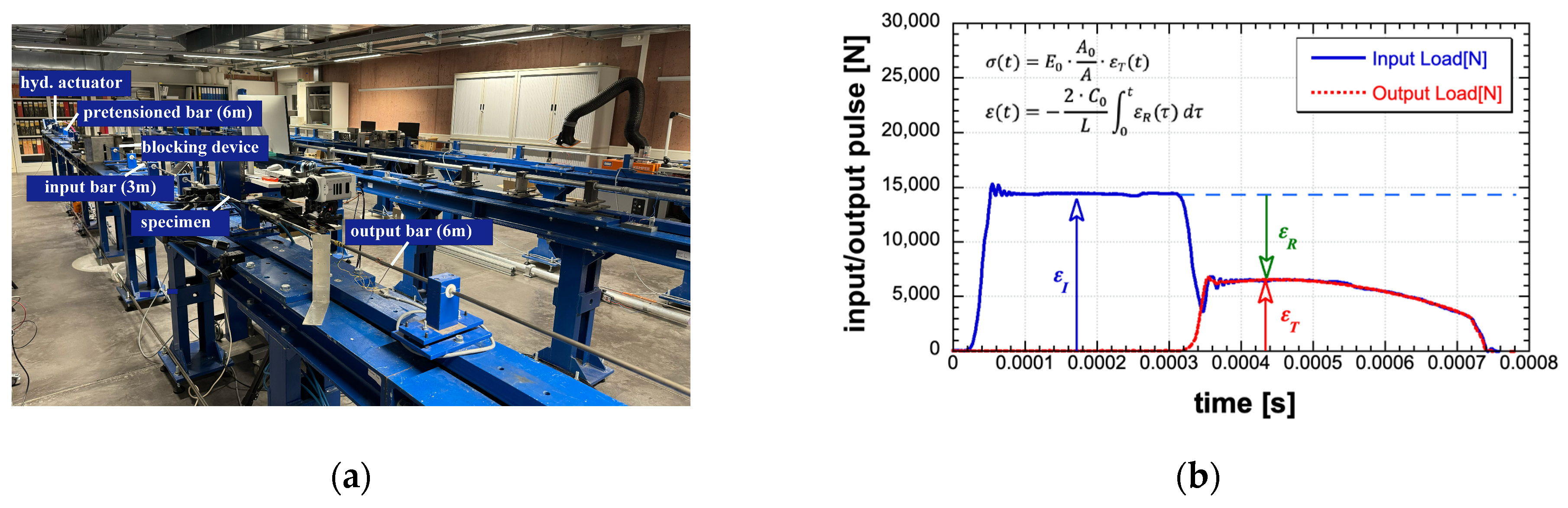
2. Material and Experiments

The experimental data’s interpretation can often be challenging due to the presence of instabilities, such as the initial peak, which are not taken into account by standard material constitutive models. Several researchers investigated the cause of these instabilities in terms of the upper and lower-yield stresses of the material. Dislocation density and velocity have been linked with the upper-yield stress [13]. The use of material models incorporating microstructural parameters is not practical for engineering purposes. It is necessary to establish relationships between upper and lower-yield values and engineering variables such as the loading pulse, structure geometry, and stress and strain tensors to perform structural assessments. Material variables defined in terms of structure and dislocation density/velocity provide phenomenological explanations for upper yield, but they do not adequately parameterize the stress–strain curve, including the upper and lower yields and their relationship to time.
The upper yield was examined by Campbell and Harding [14,15,16]. As Campbell explained, the upper yield occurs after a characteristic period of time after the onset of loading stress as a result of shear band thermal activation [15].
To analyze the response of material at high strain rates, the widely used experimental technique known as the split Hopkinson tensile bar (SHTB) was applied. It consists of a pretensioned bar and the incident and transmission bars between which the steel sample is screwed, as shown in Figure 1a. The SHTB is commonly used for the investigation of both ductile and brittle materials. In order to obtain the mechanical properties of the materials loaded at high strain rates, incident, transmitted, and reflected waves (Figure 1b) are collected and processed to obtain stress, strain and strain rate history. A detailed description of the experimental setup and tests carried out can be found in [17,18]. Figure 2a depicts the stress-versus-time curves of tests with increasing velocity, and the upper-yield stress is highlighted. Figure 2b shows the evolution of the upper-yield stress as a function of the stress rate.
Figure 3 illustrates the SEM images of fracture surfaces at different strain rates, from a quasi-static to high strain rate, at room and elevated temperature. At magnifications of 5000×, these fractographs show numerous cup-like depressions, or dimples, which indicate ductile fracture of the material. As the strain rate increases, the small dimples join to form larger dimples. The further increase in the large dimples leads to the fracture of the material. The number of dimples is greater at high strain rates (Figure 3b,c) than at quasi-static (Figure 3a), and they are also deeper. For this reason, the fracture energy and toughness of the material are higher at high strain rates than at low strain rates. At an elevated temperature and high strain rate, the fracture surface is strongly changed (Figure 3d), and the upper-yield stress decreases with the increasing temperature [18].

3. Ductile to Brittle Transition Induced by Extreme Dynamic Events

Designing structural elements requires consideration of the behaviour of brittle and ductile materials. In addition, when a structural material switches from ductile to brittle under dynamic loading, design difficulties increase. This transition occurs frequently in polymers, but it is also observed in metals [19]. Various transition states within the same material can produce mechanical plasticity or brittleness, such as crystallization temperature or exceeding the transitional loading rate [20]. However, the ductile to brittle transition is well accepted as a temperature driven phenomenon, it is not generally established how it can occur for an increase in the dynamic regime. This statement also comes from the experimental output of metallic samples subject to strain rate up to thousands of 1/s which shows typically increase in plastic stress instead of changes in brittleness.
In general framework, the sudden and relevant change in the failure mode originates from two branches of physical phenomena: (i) the viscosity of the material activated by high-speed loading and the associated plastic waves, as in the case of amorphous polymers, and (ii) the changes in the fracture and rupture process, caused by changes in the activated dislocations with changes in microcrack mechanics, including the fracture velocity and crack patterns shift through dynamic loading in a process fully belong to fracture mechanics.
As polymers are generally low resistant compared to metals, they are much more sensitive to temperature variations, showing also significant failure modifications induced to dynamic and notching conditions. For that reason, they are often used in fracture mechanic experimental investigations to study how the fracture process is affected by dynamic events [21]. It can be argued that the study of polymers illustrates phenomenological relationships that may be general in nature and can be applied to metals as well. Due to the lower-rate sensitivity of metals compared to polymers, modification from plastic to ductile failure is expected to be found in extreme deformation speed [22]. Metallic brittle behaviour is also affected by structural size, as fracture mechanics indicates that fractures are highly nonlinear geometrical processes with fracture dynamics, shear band propagation, localization, and plastic work-to-temperature transformations adding additional complexity [23,24].
Since real-scale tests are costly and complex in nature as a result of extremely low loading times, and the interference and reflection of stress waves during the test, they cannot be used to accurately identify the ductile-to-brittle transition. Due to the difficulty in recording real-time, local, and accurate responses, it is virtually impossible to record material to pure stress wave responses. The problem of defining the material model correctly and applying it to the most appropriate identification procedures is crucial for the structural design of such events. It is anticipated that the subsequent methodological framework will be based on a multiscale approach, which will allow the construction and validation of constitutive equations that incorporate a ductile-to-brittle transition caused by the competition between loading wave and shear band speed. In addition to identifying and validating material parameters by dynamic testing on split Hopkinson bars (SHBs), the model will also be applied to the numerical reconstruction of real-scale tests.

4. Strain Rate-Dependent Plasticity and Experimental, Classic, and Innovative Approaches

It is well established that the standard material models for plasticity are based on two constitutive equations, one for elastic and another for plastic fields, to define a unique yield point, which ultimately depends on variables such as the temperature, strain rate, and stress tensor [25,26]. However, these material models cannot accommodate the DBT and its structural implications due to the mathematical decomposition of multi-variable problems [27].
A similar consideration can be made for Zerilli-Armstrong [28] and empirical interpolations for Johnson-Cook, Cowper Symonds [29], and other well-known models.
The DAMP material model has been developed in this field for concrete structures’ dynamic loading, demonstrating high reliability in reconstructing and predicting real behavior under multiple material phases and transient loads [30]. Further adaptation of the DAMP model to metallic materials was made [31], with advancements in understanding the emergence of variable double-yield points under dynamic loading and the consequent increase in plastic strength.
A new material model named DAMP-PLAST was developed in this study to be applied to high-loading and extremely high loading scenarios.

5. DAMP-PLAST Model: The Plastic Propagation through Material Microstructure

A new implementation of the DAMP material model dedicated to strain rate-dependent plasticity is here proposed and named the DAMP-PLAST model.
In the DAMP-PLAST model equation set, the material strength is obtained at the considered scale of the specimen/element/structural size by considering the resultant equilibrium between multiple phases in the sub-structure created by the yield propagation, through its transient. Intentionally, the simplest modeling of the shear band propagation into a homogeneous specimen in taken in concern in Figure 4, where the key aspect is the definition of a shear band propagation speed through the specimen, progressively reducing the elastic domain into the specimen portion. In this case, the average resultant structural stress on the specimen is the goal, while the complex stress state at the tip of the shear band propagation is considered negligible in similitude to all the structural models that do not investigate the punctual stress value but the average material response, which is homogenized at the macro scale.
The specimen is subject to a main uniaxial stress wave, as occurs in the Kolsky [32] bar facilities and the pre-tensioned Hokinson bar [33], hereafter used for the dynamic testing (Figure 4).
The microcrystalline metal structure of the specimen houses a wide range of dislocations, among which, some are activated first upon reaching the yield stress, σ 0 . Those activation points are considered spaced with a characteristic length, in accordance with the nature of the material. The shear bands begin when the yield stress at an activated dislocation occurs and end when the shear bands propagate fully between the closer activated dislocations, for which the mentioned distance is considered a material microcrystalline and thermal property. According to the experimental observations of [34,35], the process of shear band propagation ends at the reaching of a certain length, L d [36].
Since the yield starts during activation, the transient process of shear band propagation creates a loss of homogeneity in the specimen, as the specimen’s mesoscopic scale is larger compared to the microcrystalline size. Following this idea, the variables to define the shear band are chosen: shear band characteristic length and its propagation speed. Those variables are later identified by the mean of the experimental stress–strain response at various deformation speeds.
Then, the average material resultant strength is calculated.
Once σ 0 is reached (Equation (1)), the shear band propagation starts from initialization [37], proceeding with the velocity of propagation, v s b (Equation (2)), and progressively increasing the shear band length, L s b , up to the point that it reaches the characteristic shear band, L d (Equation (3)). The value of v s b is assumed constant, and it is dependent on the material type; however, its dependency on the stress state can be later. introduced. Also, the ratio between the characteristic shear band length and the shear band speed creates a characteristic propagation time, which affects the whole material response. As v s b is a known material parameter, the yield propagation allows us to calculate the instantaneous yielded, A p l t , and elastic, A e l , cross-section specimen portions of the specimen cross-section A s (Equations (4) and (5)). The elastic or plastic phase behaves with its constitutive model (Equations (6) and (7)), which is necessary to calculate the total transient stress in the structure. As an example, a linear hardening, H , plastic response is used (Equation (8)); however, an arbitrary plastic stress–strain can be used in an identical manner, upgrading the constitutive model.
The initialization of the plastic phase is coincident with the reaching of the critical stress at the active dislocation:
σ t ,   x , y , z σ 0   t = t 0 = 0
where σ 0 and v s b are material parameters.
The shear propagation process ends when the single shear band of instantaneous length, L s b t , reaches a characteristic length, L d , which is a material parameter too.
L s b t = v s b × t y t 0
i f   L s b t < L d   c o n t i n u e   u p   t o   L s b t L d
From the yield propagation, a characteristic yielding time, t c y , is extracted as the total time required to yield the material under incremental dynamic loads.
t c y = t y t 0 = L d v s b
In a generic time during the yielding, the total specimen section, A s , is composed by the material domain still in the elastic regime by A e l and the ones already plasticized with value A p l . Through time, the elastic domains reduce their area in favor of the plasticized ones.
A s = A e l t + A p l t
The plasticized area grows by a geometrical rule, in accordance with the increase in the shear band length. The circular propagation is considered in the following:
A p l t = π × ( L s b t ) 2 4
The specimen’s macroscopic scale hosts a multitude of activation points in the crystalline microstructure. The yield propagation is composed of the simultaneous activation of many yield nucleation points for which the number through the specimen area is a material property.
Once the yield starts, yielded and elastic specimen areas are activated by their respective constitutive models. The linear elastic constitutive model is taken for the unyielded area (8), where the stress propagating through the elastic phase coincides with the dynamic input wave carrying the incremental load to the specimen. As in the SHB case in the transient phase of the SHB tests, a constant loading rate is a good approximation of reality.
σ e l t = E × ϵ e l = σ l o a d t
σ l o a d t = σ 0 + σ ˙ × t ( t = 0   w h e n   σ = σ 0 )
For the yielded area, the linear elastic–plastic constitutive model is considered:
σ p l t = σ 0 + H ϵ p l
where H is the hardening constant.
The specimen’s structural response is then calculated by averaging each subdomain that contributes:
σ s p c t = σ e l t × A e l + σ p l ( t ) × A p l / A s
Equations (1)–(9) form a material constitutive equation set that can be solved by explicit step-by-step integration, providing, in their output, the material dynamic response.
With the purpose of implementing them into the LsDyna [38] numerical solver, the material model by a user-defined subroutine and Equations (1)–(9) are recombined.
The parameter ψ y (Equation (10)) is defined to calculate, at the actual time, the fraction of the cross-section already reached by the shear band propagation ( 0 ψ y 1 ) . This parameter is suitable to compute any of the geometrical propagation of yield starting from initialization points. Parameter ψ y is 0 at the start of the yield process, where the entire cross-section is computed in the elastic regime. When ψ y is equal to 1 at the end of the shear band propagation, the section is fully plasticized. As a result, Equation (11) can describe the equivalent a-dimensional parameter, ψ e l , for the elastic field.
ψ y t = L s b t L d
ψ e l t = 1 ψ y ( t )
Consequently, the specimen’s cross-section area ( A s ) can be calculated as the sum of the elastic ( A e l ) and plastic areas ( A p l ) that are a function of parameter ψ y .
A p l t = A s × ψ y t
A e l t = A s × 1 ψ y ( t )
By recombining the latest definitions, the specimen response becomes as follows:
σ s p c ε , t = σ 0 + σ ˙ × t × 1 ψ y t + σ 0 + H × ϵ p l × ψ y t
Equation (14) combines the static yield, occurring when the time is zero at the beginning of the yield process. Also, the equation takes into account additional yield strengths up until the end of the yield, when the model converges to the standard plastic flow model. During the yielding transition, a yield-stress increase comes from the loading rate and related wave propagation into the un-yielded domains. The balance between the loading rate and the yield area transition defines the magnitude of the incremental yield stress transferred because of the dynamic nature of the loads.
Taking into account the plastic flow’s dependence on the strain rate, the strain rate dependency is included in Equation (15), where an arbitrary S r function can be defined in the strain-rate field.
σ s p c t ,   ε ˙ , ε = S r ε ˙ × σ s p c ε , t

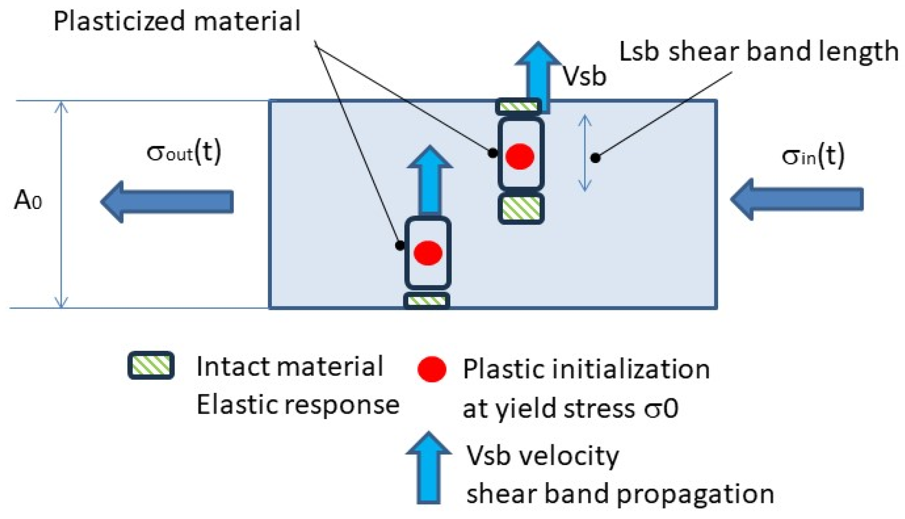
6. The Brittle Behavior as a Physical Limit for the Material Due to Shear-Band-to-Loading-Wave Velocities

According to the DAMP-PLAST constitutive equations, the yield propagation acts in a characteristic time, t c y , that can be computed by the ratio between the two principal material parameters, the characteristic shear band length and shear band speed:
t c y = L d v s b
Meanwhile, as the shear band propagates, the loading stress wave continuously moves through the continuum, raising the stress by the loading rate, σ   ˙ (Equation (17)).
σ ˙ = σ t
While the yield saturates the material section, the dynamic loads increment the local stress in the unyielded material domains. The upper limit of the stress induced by the dynamic loading wave can be estimated as follows:
σ m a x = σ y +   σ ˙ × t c y
The interplay between the value of t c y and the loading rate, σ ˙ , creates a variety of possibilities in regard to the value of the local stress reached in the material, while the initialized dislocation starts the process of the yielding.
A critical value of the loading rate, σ c ˙ , was found when the loading rate caused the fracture stress, R m , to be reached in a shear band length’s intermediate point before the shear band completed its propagation through its characteristic length (Equation (19)). Over this critical loading rate, the material is loaded in the whole microstructure to its failure limit, and the plastic flow is no longer able to provide a mechanism of large deformation through incremental stresses. Inhibiting the large deformations typical of the plastic flow phase finally triggers the start of the dynamic brittleness.
σ c ˙ = R m σ y t c y
Over the value of the critical loading rate, σ c ˙   , a new process of fracture localization and deformation reduction occurs in the material, with distinguished behavior compared to the plastic flow evolution caused by a loading rate lower than the critical one.
The final higher localization and strongly reduced deformations lead to material brittleness caused by extreme loading scenario, even with a material characterized by plastic deformations in lower loading rate regime.
As a range of magnitude, a steel plate with a 1000 MPa yield and 2000 MPa maximal strength, with a v s b = 20 m/s shear band speed and L d = 0.8 mm characteristic shear band length, has a 25 TPa/s critical loading rate, corresponding to a blast event of 1 kg TNT contact charge (as lately obtained in the example, obtaining 45 TPa/s with a slab thickness of 20 mm).

Ductile–Brittle Transition: The Critical Kinetic Energy Content

According to Griffith’s fracture theory, a plastic-to-brittle metallic transition can be found due to the increase in the stress wave energy content, E i n p (Equation (20)), overcoming the dynamic material failure energy, E d y n (Equation (21)), which is multiplied by the stress intensity factor, K 1 , to obtain the static failure energy, E s t a t . In the extreme loading scenario, the incoming stress wave is associated with a pressure wave energy that is higher than the fracture energy of the material. In this case, like the previously developed challenge between the stress wave and shear band velocities, strain localization and point failure emerge, leading the entire structure to display brittle behavior.
For the input wave, the harmonic wave led to the elastic energy content:
E i n p = σ i n p 2 2 E
E d y n = K 1 E s t a t
The correspondent limit condition for the amplitude of the input wave is found to be σ i n p _ c r i t i c , which is the limit value of loading rate separating the strain rate plasticity field to the brittle behavior the material response:
σ i n p _ c r i t i c = 2 E K 1 E s t a t
Equation (20)’s output is the maximal stress intensity of the input wave leading to the breaking of the material, as the wave introduces an energy content that is higher than its maximal absorption capability through the deformation and failure process. At higher values, the material became unable to stand a progressive failure and failed within the time described by the wave propagation speed. Equation (20), associated with the first ductile-to-brittle transition limit in Equation (18), defines the bottom and upper field of existence of the brittle material’s response. In a practical way, Equation (20) is limiting its application in hypervelocity impacts, since if the input wave travels through the material with a loading rate lower than (19), the material fails before the maximal amplitude is reached.

7. Identification of DAMP-PLAST Material Parameters

Some of the literature proposed to examine the post-mortem specimen with microscopic techniques to characterize, when possible, the structures of shear band propagation to measure the final length of the band. Shear band propagation speed can also be measured experimentally using Hopkinson bar facilities and other experimental techniques, such as infrared emission measurements due to plastic flow dissipation. Those last improvements can also be considered further experimental validation of the material model parameters.

7.1. DAMP-PLAST Material Model Identification

A key material property that determines dynamic material behavior is the shear band length and propagation speed. Previously, it has been demonstrated that yields behave according to a characteristic time associated with the material, and as stress waves propagate into solids, dynamic incremental loads cause additional stress waves to flow into the material during yield propagation as a consequence. During the transients of yield propagation, this stress flow contributes an additional element of strength to the specimen. Equation (15) can be used to calculate the total maximum strength of the material during yield. Due to this contribution, the material produces a dynamic upper yield that is higher than the static yield. A correlation is established between the upper-yield value and the characteristics of the material and the loading-rate characteristics. Based on the upper-yield value, the following parameters can be identified in the DAMP-PLAST dynamic material model:
(a)
Via static tests, the yield stress and static plastic response are found;
(b)
Via SHB tests, the strain rate-dependent plasticity is identified;
(c)
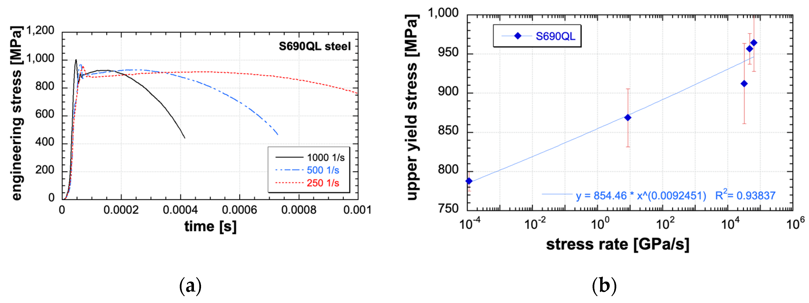
Via the use of SHB tests, high loading rates are obtained, and upper yield appears on the output signal (see Figure 2a). By the amplitude of the upper yield and knowing the loading rate, the identification starts. The experimental response of SHB tests can be used as a starting point for applying the test numerical reconstruction and tuning the numerical model up so that the virtual and real experimental signals are identical. The fitting is made by modifying the shear band propagation speed and the characteristic propagation length while the initial yield point has already been obtained by the static test. This method is fully engineer-oriented, as it uses repeatable experiments that are fully focused on a specific loading rate;
(d)
Finally, the critical brittle loading rate is found via the analytic relation (18).
At this point, all the material model parameters and the dynamic brittleness are identified, and the material model can be applied to a structural case.

7.2. DAMP-PLAST Material Response Triggered by the Yielding Propagation Time Driving the Failure-Mode Changes

Equation (15) represents the essential mechanism moving the material through several distinguished responses: elastic, quasi-static elastic–plastic, dynamic rate-dependent, upper yield with dynamic rate-dependent, and finally brittle. The DAMP-PLAST material model response scheme is depicted in Figure 5 for increasing loading rates. The curve results from the implementation of the DAMP-PLAST material model in the LsDyna numerical solver. A loading rate is assigned as input in the split Hopkinson bar configuration, and the material strength is obtained at the output (Figure 4).
The following distinct material behaviors are possible:
(1)
Quasi-static response: As the loading rate is very small, the yield occurs at the static value. The yield acts instantaneously compared to the physical time by which the loads rise over the structure.
(2)
Intermediate strain and loading rates are characterized by a loading rate smaller than the critical loading rate but big enough to create a significant stress increase while the shear band completes its path. In this case, the material acts in accordance with the strain rate-dependent plasticity models, resulting in an increase in the plastic flow within the loading rate. Additionally, in the elastic-to-plastic transition, the upper yield can appear or not, with variable intensity dependent on the possible combination between the shear band propagation, the loading rate, and the yield increase due to the classical strain rate-dependent plasticity.
(3)
Extreme loading rates, characterized by a loading rate higher than the critical loading rate, brittle behavior, fracture localization, and overall deformation reduction, are found.
In Figure 6 a major detail over the brittle failure transition is made by tracing through the load rate the upper-yield value and the failure strain. The maximal value of the upper-yield strength was found to be in accordance with the critical loading rate, at which the failure strain reduces drastically and multiple fractures simultaneously initialize in the material. Through the double vertical axis, the two meaningful structural magnitudes of upper-yield and failure stress are plotted according to the material properties and through the increasing of the loading rate. As a sample of the application, the correlation between the upper yield and the loading rate is used, as mentioned, in the material identification phase, while the major outcome of dynamic brittleness is obtained.

8. Application of DAMP-PLAST Model: Structural Mesh Size vs. Mesh Sensitivity

For engineering purpose, the DAMP-PLAST material model should be applied to structural cases, and the mesh-size adaption is required in the numerical calculation.
The mesh size has a straightforward impact on the computational capability to solve the stress–strain field of the mechanical body. In the simulation of the blast, the mesh-size choice is conditioned by several factors, some of which are in opposition to the ideal requirement to work with fine mash to obtain full convergence in the structural field:
(i)
Considering the real-scale event, the mesh size that the engineer can apply is generally macroscopic due to the structure size and computational effectiveness. To avoid large systematic errors, the material properties should be tuned to the mesh size used in the real-scale application [39].
(ii)
Having as the actual goal the SHB test reconstruction dedicated to the real test simulation, the application requires the tuning of the material properties on the finest mesh size, in accordance with the true stress–strain in the necking region during the plastic flow but applying the tuning of the SHB signal using the structural mesh size used to compute the final real-scale blast event.
(iii)
With the goal of identifying the yield propagation speed as a principal parameter linked to the brittle transition prediction in the DAMP-PLAST material model, it is important to note how the upper yield occurs when the specimen is not yet subject to large deformation; hence, the geometrical non-linearities do not apply. During the early loading of the specimen subject to uniform stress through the cross-section, the element formulation proposed in the DAMP-PLAST model has very limited sensitivity in regard to mesh size, as intrinsically the element formulation incorporates at the value of the shear band length and speed.
On experimental physical based, the upper yield acts in the range of a 20 μs duration, corresponding to 20 m/s speed over an interlocus of 0.1 mm in the identified model parameters. As the interdistance is smaller compared to the element size, the element formulation itself became invariant to the mesh size for the upper-yield reconstruction, as independently from the mesh size, the same propagation time is calculated. Finally, a poor mesh sensitivity is found (Figure 7).
As a result of the previous argument, the validation of the DAMP-PLAST material model can be conducted using a rough mesh, with the advantage of a calculation time without effects on the identification of the yield transition. The value of the propagation speed of such a calibration can be applied at any mesh scale.

9. Model Assessment of Critical Blast Charge over Thick Metal Slab

To challenge the DAMP-PLAST material model, a simulation of a blast test was performed and compared with the *MAT_PIECEWISE_LINEAR_PLASTICITY (hereafter, MatPlast) multilinear model.
An explosive charge was out into contact with thick 12 mm and 40 mm slabs (see Figure 8a). The explosive mass was chosen to breach the slab. A second test case was calculated, with the explosive placed at a higher stand-off distance, with an increased explosive mass to breach the slab too (see Figure 8b). Over the 12 mm slab, the contact charge is 1 kg TNT, while at distance of 1 m, 9 kg of TNT is applied. In the case of the 40 mm slab, the contact charge is 4 kg of TNT, and at a distance of 1 m, 20 kg of TNT is applied.
The numerical response was calculated using the fluid–structure interaction of the LsDyna arbitrary Lagrangian–Eulerian technique. Two branches of simulations were made using the DAMP-PLAST model identified over S690QL steel, and with the classical MatPlast material model. The results are reported in Table 1 and Table 2.
The stress vs. time for the 12 mm slab is illustrated in Figure 9. In the case of a contact charge, the loading rate is higher than that of a one-meter charge distance. According to the DAMP-PLAST material model, these phenomena lead to brittle failure at over-critical-loading rates, unlike the classical material model that predicts elastic–plastic failure at all times. Plastic failure is possible for the slab with a 12 mm thickness and a one-meter stand-off distance because of the lower loading rate. The DAMP-PLAST model behaves in brittle regime in both cases for 40 mm slabs, whereas the classical material model acts in strain rate plasticity failure when the explosive quantity is high.
In Figure 10, the brittle fracture of the 12 mm slab for the contact charge obtained with the DAMP-PLAST material model is shown.

Results

Standard material models are insensitive to the loading rate, while the plastic strain rate governs the hardening, and similar structural outputs are obtained in the two-standoff distances.
By using the DAMP-PLAST material model, the sensitivity to loading rate is taken into account, and numerical results differ from the large standoff distance and the close contact range for the 12 mm slab, but breaching is brittle in both cases for the 40 mm slab (Figure 11).
In the 12 mm case, the threshold in the blast distance was identified that affects the brittle transition for the blast model, showing high differences in structural outputs compared with the standard model and the DAMP-PLAST model (Figure 12).
When modifying the charge distance, progressively, the strain rate-dependent plasticity is associated with upper-yield stiffening in the response of the slab until the brittle failure occurs for extreme loading rates.

10. Conclusions

Starting from the need to better understand the ductile-to-brittle failure of metallic structures subject to dynamic loads, the new DAMP-PLAST material model was implemented. The key element is the modeling of the elastic-to-plastic transition by a finite time process in the material constitutive equation. It was shown that, as a consequence of the stress wave propagation during the shear band propagation process, the specimen increases the dynamic yielding value in accordance with the loading rate and the characteristic yield propagation time. The DAMP-PLAST constitutive equation was developed by taking as fundamental parameters the yield propagation speed and the shear band characteristic length, along with the static yield strength and the ultimate strength. The material model shows a variety of responses, from static to extreme loading scenarios, including upper and lower yield for high strain rates, and plastic-to-brittle failure in extreme loading rate regime. The upper and lower yields were taken into consideration as a method to identify the material shear band propagation speed parameter by which the ductile-to-brittle failure transition was analytically extrapolated, finding a critical loading-rate value that ignited the structural brittle failure.
The critical loading rate inducing material brittleness was estimated for metals in the scale of loading rates achieved by contact charge blast with one-kilo mass TNT over slabs with some millimeters in thickness.
After the constitutive equation development and implementation in LsDyna software (LS-DYNA R15.0.2 released 2024/03), a mesh-sensitivity investigation was applied. Limited mesh sensitivity was found regarding the yield sensitivity, while state-of-the-art mesh sensitivity was attributed to the plastic stress and strain.
The research opens up a new perspective in regard to the structural analysis of blast events, wherein the state-of-the-art rate-dependent material model fails to predict structural brittleness and to provide a methodological approach to identify the trigger physical parameters inducing modification in failure mode. The future application of the material model to simulate real-scale tests with a double-failure mode is highly recommended to test the predictive capability of the presented methodology.

Author Contributions

Conceptualization, G.R. and E.C.; methodology, G.R.; software, G.R.; validation, G.R.; formal analysis, G.R.; investigation, E.C. and G.R.; data curation, G.R.; writing—original draft, G.R.; visualization, E.C.; testing, E.C.; funding acquisition, E.C.; project administration, E.C.; supervision, E.C.; writing—review and editing, E.C. and G.R. All authors have read and agreed to the published version of the manuscript.

Funding

This research received no external funding.

Data Availability Statement

The original contributions presented in the study are included in the article, further inquiries can be directed to the corresponding author.

Conflicts of Interest

The authors declare no conflicts of interest.

References

  1. Koyama, M.; Shimomura, Y.; Chiba, A.; Akiyama, E.; Tsuzaki, K. Room-temperature blue brittleness of Fe-Mn-C austenitic steels. Scr. Mater. 2017, 141, 20–23. [Google Scholar] [CrossRef]
  2. Darnbrough, J.; Roebuck, B.; Flewitt, P. The influence of temperature and grain boundary volume on the resistivity of nanocrystalline nickel. J. Appl. Phys. 2015, 118, 184302. [Google Scholar] [CrossRef]
  3. Albertini, C.; Cadoni, E.; Solomos, G. Advances in the Hopkinson bar testing of irradiated/non-irradiated nuclear materials and large specimens. Phil. Trans. Royal Soc. A 2015, 372, 20130197. [Google Scholar] [CrossRef] [PubMed]
  4. Yang, X.; Zhang, B. Material embrittlement in high strain-rate loading. Int. J. Extrem. Manuf. 2019, 1, 022003. [Google Scholar] [CrossRef]
  5. Dowding, I.; Schuh, C.A. Metals strengthen with increasing temperature at extreme strain rates. Nature 2024, 630, 91–95. [Google Scholar] [CrossRef] [PubMed]
  6. Majzoobi, G.H.; Mahmoudi, A.H.; Moradi, S. Ductile to brittle failure transition of HSLA-100 Steel at high strain rates and subzero temperatures. Eng. Fract. Mech. 2016, 158, 179–193. [Google Scholar] [CrossRef]
  7. Gauder, P.; Seidenfuß, M. Experimental and numerical investigations of tensile specimens containing multiple flaws in the ductile-to-brittle transition region. Eng. Fract. Mech. 2021, 248, 107714. [Google Scholar] [CrossRef]
  8. Klepaczko, J.R. Plastic shearing at high and very high strain rates. J. Phys. IV 1994, 4, C8–C35. [Google Scholar] [CrossRef]
  9. Su, G.; Su, Q.; Sheng, J.; Wang, B.; Zhang, H.; Du, J.; Zhang, P.; Shen, X.; Liu, Z. Modelling of ductile fracture in pure iron considering the ductile–brittle transition at very high strain rate. Eng. Fract. Mech. 2023, 281, 109145. [Google Scholar] [CrossRef]
  10. Xu, Z.; Liu, Y.; Sun, Z.; Hu, H.; Huang, F. On shear failure behaviors of an armor steel over a large range of strain rates. Int. J. Imp. Eng. 2018, 118, 24–38. [Google Scholar] [CrossRef]
  11. Li, Y.; Pallaspuro, S.; Ren, X.; He, J.; Kömi, J.; Zhang, Z. A multi-barrier model assisted CAFE method for predicting ductile-to-brittle transition with application to a low-carbon ultrahigh-strength steel. Mech. Mat. 2021, 153, 103669. [Google Scholar] [CrossRef]
  12. Needleman, A.; Tvergaard, V. Numerical modeling of the ductile-brittle transition. Int. J. Fract. 2000, 101, 73–97. [Google Scholar] [CrossRef]
  13. Orowan, E. Problems of plastic gliding. Proc. Phys. Soc. 1940, 52, 8–22. [Google Scholar] [CrossRef]
  14. Campbell, J.D. Dynamic plasticity: Macroscopic and microscopic aspects. Mat. Sci. Eng. 1973, 12, 3–21. [Google Scholar] [CrossRef]
  15. Campbell, J.D.; Ferguson, W.G. The temperature and strain-rate dependence of the shear strength of mild steel. Philos. Mag. 1970, 21, 63–82. [Google Scholar] [CrossRef]
  16. Harding, J. Effect of High strain rate on the room temperature strength and ductility of five alloy steels. J. Iron Steel Inst. 1972, 210, 425–432. [Google Scholar]
  17. Cadoni, E.; Forni, D. Strain-rate effects on S690QL high strength steel under tensile loading. J. Constr. Steel Res. 2020, 175, 106348. [Google Scholar] [CrossRef]
  18. Cadoni, E.; Briccola, D.; Dotta, M.; Forni, D. Combined effect of elevated temperature and high strain rates on S690QL high strength steel. J. Constr. Steel Res. 2022, 199, 107519. [Google Scholar] [CrossRef]
  19. Escobedo, J.P.; Brown, E.N.; Trujillo, C.P.; Cerreta, E.K.; Gray, G.T.I. The effect of shock-wave profile on dynamic brittle failure. J. Appl. Phys. 2013, 113, 103506. [Google Scholar] [CrossRef]
  20. Scheibert, J.; Guerra, C.; Cйlariй, F.; Dalmas, D.; Bonamy, D. Brittle-Quasibrittle Transition in Dynamic Fracture: An Energetic Signature. Phys. Rev. Lett. 2010, 104, 045501. [Google Scholar] [CrossRef]
  21. Ravi-Chandar, K. Dynamic Fracture; Elsevier Science: Amsterdam, The Netherlands, 2004. [Google Scholar]
  22. Torre do Vale Arriaga e Cunha, M. Stability Analysis of Metals Capturing Brittle and Ductile Fracture through a Phase Field Method and Shear Band. Ph.D. Thesis, Columbia University, New York, NY, USA, 2016. [Google Scholar] [CrossRef]
  23. Knott, J. Brittle fracture in structural steels: Perspectives at different size-scales. Phil. Trans. Royal Soc. A 2015, 373, 20140126. [Google Scholar] [CrossRef] [PubMed]
  24. Qin, K.; Yang, L.M.; Hu, S. Interpretation of Strain Rate Effect of Metals. In Dynamic Behavior of Materials; Song, B., Casem, D., Kimberley, J., Eds.; Springer International Publisher: New York, NY, USA, 2014; Volume 1, pp. 21–27. [Google Scholar]
  25. Johnson, G.R.; Cook, W.H. Fracture characteristics of three metals subjected to various strains, strain rates, temperatures and pressures. Eng. Fract. Mech. 1985, 21, 31–48. [Google Scholar] [CrossRef]
  26. Johnson, G.; Holmquist, T.M.; Meyer, M.A. (Eds.) Chapter A Computational Constitutive Model for Brittle Materials Subjected to Large Strains, High Strain Rates, and High Pressures. In Shock Wave and High-Strain-Rate Phenomena in Materials; CRC Press: Boca Raton, FL, USA, 1992; pp. 1075–1081. [Google Scholar]
  27. Selyutina, N.; Petrov, Y. Comparative Analysis of Dynamic Plasticity Models. Rev. Adv. Mat. Sci. 2018, 57, 199–211. [Google Scholar] [CrossRef]
  28. Zerilli, F.J.; Armstrong, R.W. Dislocation mechanics based constitutive equation incorporating dynamic recovery and applied to thermomechanical shear instability. AIP Conf. Proc. 1998, 429, 215–218. [Google Scholar]
  29. Cowper, G.; Symonds, P. Strain-Hardening and Strain-Rate Effects in the Impact Loading of Cantilever Beams; Division of Applied Mathematics, Brown University: Brown, RI, USA, 1957. [Google Scholar]
  30. Riganti, G.; Cadoni, E. Multiple Pseudo-Plastic Appearance of the Dynamic Fracture in Quasi-Brittle Materials. Materials 2020, 13, 4976. [Google Scholar] [CrossRef] [PubMed]
  31. Riganti, G.; Cadoni, E. Numerical simulation of the high strain-rate behavior of quenched and self-tempered reinforcing steel in tension. Mat. Des. 2014, 57, 156–167. [Google Scholar] [CrossRef]
  32. Kolsky, H. An Investigation of the Mechanical Properties of Materials at very High Rates of Loading. Proc. Phys. Soc. Sect. B 1949, 62, 676. [Google Scholar] [CrossRef]
  33. Albertini, C.; Montagnani, M. Testing techniques based on the SHPB. Inst. Phys. Conf. Ser. 1974, 21, 22–32. [Google Scholar]
  34. Bigoni, D.; Dal Corso, F.; Dal Corso, F. The unrestrainable growth of a shear band in a prestressed material. Proc. R. Soc. Lond. A 2008, 464, 2365–2390. [Google Scholar] [CrossRef]
  35. Xue, Q.; Meyers, M.; Nesterenko, V. Self organization of shear bands in stainless steel. Mat. Sci. Eng. A 2004, 384, 35–46. [Google Scholar] [CrossRef]
  36. Liu, C.; Roddatis, V.; Kenesei, P.; Maaßs, R. Shear-band thickness and shear-band cavities in a Zr-based metallic glass. Acta Mat. 2017, 140, 206–216. [Google Scholar] [CrossRef]
  37. Johnston, W.G.; Gilman, J.J. Dislocation Velocities, Dislocation Densities, and Plastic Flow in Lithium Fluoride Crystals. J. Appl. Phys. 1959, 30, 129–144. [Google Scholar] [CrossRef]
  38. LsDyna. LsDyna Keyword and Theory Manual. Available online: www.dynasupport.com/manuals (accessed on 1 March 2024).
  39. Yudhifa, C.; Satriawan, G.; Harwijayanti, W.; Ridwan, R.; Prabowo, A.R.; Fajri, A.; Cho, J.H.; Do, Q.T. Nonlinear analysis of an idealized I-beam member: An investigation of mesh size on the structural behaviors using FE approach. Proc. Struct. Int. 2023, 48, 50–57. [Google Scholar]
Figure 1. Experimental setup: (a) split Hopkinson tensile bar and (b) raw signals.
Metals 14 00807 g001
Figure 2. Stress-versus-time curves (a) and upper-yield stress as a function of stress rate (b).
Metals 14 00807 g002
Figure 3. SEM images of fracture surface at: (a) quasi-static (20 °C); (b) 250 s−1 (20 °C); (c) 1000 s−1 (20 °C); (d) 1000 s−1 (500 °C).
Metals 14 00807 g003
Figure 4. Test specimen subject to dynamic loading with shear band propagation in place.
Metals 14 00807 g004
Figure 5. Example of engineering stress–strain response resulting from the DAMP-PLAST material model integrated into different dynamic regimes, from static to extreme dynamic.
Metals 14 00807 g005
Figure 6. The upper yield modeled by DAMP-PLAST material, the plastic-to-brittle transition predicted for the material model, and the localization of experimental dynamic tests.
Metals 14 00807 g006
Figure 7. Limited mesh sensitivity in the upper-yield computation by the DAMP-PLAST material model. Results of the SHB test simulation.
Metals 14 00807 g007
Figure 8. Test case scheme: contact charge and 1 mm stand-off over a metallic slab of 12 and 40 mm.
Metals 14 00807 g008
Figure 9. Time history of the stresses of a finite element closer to the epicenter of the blast, both in the case of a contact charge and in the case of one meter of 12 mm simulated slab.
Metals 14 00807 g009
Figure 10. Examle of brittle fracture of 12 mm slab, DAMP-PLAST material model.
Metals 14 00807 g010
Figure 11. Results on 40 mm slab: (a) slab deformation and failure by plastic work in the case of the standard rate plasticity model, and (b) failure by brittle fragmentation and localized fracture by DAMP material model.
Metals 14 00807 g011aMetals 14 00807 g011b
Figure 12. Failure results for same condition: (a) brittle fracture of 12 mm slab, DAMP-PLAST material model; (b) localized fracture by plastic deformation, MatPlast model.
Metals 14 00807 g012
Table 1. Overall blast-test results’ comparison, 12 mm.
Test CaseMaterial ModelResultFailure by
Contact chargeMatPlastPlastic failureDeformation
Contact chargeDAMP-PLASTBrittle failureFracture and debris
1 m stand-offMatPlastPlastic failureDeformation
1 m stand-offDAMP-PLASTPlastic failureDeformation
Table 2. Overall blast-test results’ comparison, 40 mm.
Test CaseMaterial ModelResultFailure by
Contact chargeMatPlastPlastic failureDeformation
Contact chargeDAMP-PLASTBrittle failureFracture and debris
1 m stand-offMatPlastPlastic failureDeformation
1 m stand-offDAMP-PLASTBrittle failureFracture and debris
Disclaimer/Publisher’s Note: The statements, opinions and data contained in all publications are solely those of the individual author(s) and contributor(s) and not of MDPI and/or the editor(s). MDPI and/or the editor(s) disclaim responsibility for any injury to people or property resulting from any ideas, methods, instructions or products referred to in the content.

