Article

Effect of Silicon on the Martensitic Nucleation and Transformation of 301 Stainless Steel under Various Cold-Rolling Deformations

1
College of Materials Science and Engineering, Taiyuan University of Technology, Taiyuan 030024, China
2
Technology Center, Taiyuan Iron and Steel (Group) Company Ltd., Taiyuan 030003, China
*
Authors to whom correspondence should be addressed.
Metals 2024, 14(7), 827; https://doi.org/10.3390/met14070827
Submission received: 30 June 2024 / Revised: 13 July 2024 / Accepted: 17 July 2024 / Published: 18 July 2024
(This article belongs to the Special Issue Advances in Metal Rolling Processes)

Abstract

:
A systematic study was conducted on the influence of silicon on the microstructure, stress distribution, and martensitic nucleation and transformation of 301 metastable austenitic stainless steel during cold-rolling deformation. When the deformation amount of conventional 301 stainless steel is ≤20%, the amount of martensite transformation is very small. When the deformation amount is ≥30%, the amount of martensite transformation significantly increases. The introduction of Si significantly improves the amount of martensite transformation and the uniformity of deformation. 301Si-H has a significantly higher amount of martensite in the same deformation microstructure than conventional 301Si-L with a lower silicon content. Increasing the Si content decreases the stacking fault energy of 301 stainless steel. During deformation, Si tends to cluster at the grain boundaries, reducing stacking fault width and increasing dislocation density, creating sites for shear martensite nucleation at the grain boundaries. Simultaneously, significant deformation encourages the formation of deformation twins and facilitates martensite nucleation.

1. Introduction

With the vigorous development of microfabrication and microelectronic technology, the demand for micro-sized metal foils and their forming processes is increasing [1,2]. This material exhibits unique “size effects” due to its ultra-fine grain structure at the sub-micrometer level formed through severe deformation, resulting in excellent strength and hardness [3,4]. Austenitic stainless steel (ASS) possesses excellent corrosion resistance and good formability, but faces limitations in applications due to its relatively low yield strength [4,5,6]. Particularly, high strength and high ductility austenitic stainless steel with nano/submicron grain structure has been synthesized through thermo-mechanical process consisting of severe cold-rolling and annealing [7,8,9]. Currently, efforts are being made to implement a multi-stage controlled rolling to 301 (1Cr17Ni7) metastable ASS for preparing the thin rolled sheets as much as possible while ensuring strength and quality [10,11,12]. The 301 ASS undergoes severe deformation, resulting in the formation of deformed martensite. The martensite phase is unstable at high temperatures and can revert to fine-grained austenite through annealing at elevated temperatures, thereby strengthening the stainless steel [13,14,15]. However, some challenges such as uneven distribution of martensite, inconsistencies in deformation, and refinement across different regions, as well as high stress concentration, still exist in the fabrication process.
The reverse transformation from martensite to austenite and the subsequent refinement and recrystallization of austenite plays a significant role in improving the microstructure [16,17]. The reverse transformation occurs after annealing, reducing the hard and brittle martensite content [18,19], decreasing dislocation density and internal stress [20,21], while also generating more low-energy grain boundaries from the recrystallization process [22,23,24]. The content and distribution of martensite formed before the reverse transformation of austenite directly impacts the degree of subsequent grain refinement. Studies have shown that deformation-induced martensitic transformation [25,26] and twinning [27] of metastable austenite are expected to enhance plasticity during deformation, known as transformation-induced plasticity (TRIP) and twinning-induced plasticity (TWIP) effects. Therefore, controlling the transformation from austenite to martensite during plastic deformation are crucial for refining the grains of austenitic stainless steel used in precision strip steel [28,29].
The influence of alloying elements on the austenitic transformation behavior during cold-deformation has been widely studied. For instance, the severity of martensite formation (ε and α′) increased with increasing C content, and α′ martensite was formed mainly in austenitic stainless steel lacking Mo, whereas a high Mo content led to a strong ε martensite structure, i.e., a weak α′ martensite [30]. An increase in N content is beneficial for the formation of martensite during the cold-rolling process of metastable austenitic stainless steel [31]. The presence of silicon (Si) in austenitic stainless steels has been found to play a crucial role in the deformation process. Studies have shown that silicon can promote martensite nucleation and transformation, leading to more uniform deformation in Fe-Mn TWIP steel [32]. Additionally, an increase of silicon content has been associated with changes in the post-deformation microstructure, particularly due to its effect on the stacking fault energy (SFE) of Cr-Ni austenitic stainless steels [33]. Although silicon contributes to enhancing strain hardening rates in martensitic steels [34], its precise influence on martensite nucleation and transformation processes and deformation behavior requires further clarification.
This paper focuses on the microstructure evolution of 301 stainless steel with two different silicon contents after cold-rolling deformations. Two types of 301 samples with the addition of 0.58 and 1.41 wt.% Si, namely 301Si-L (low Si) and 301Si-H (high Si), were prepared. The microstructure and deformation mechanisms of two 301 stainless steel with 10%, 20%, 30%, and 40% cold-rolling were explored, respectively. The deformation induced martensitic formation and transformation in different Si-containing 301 samples was further investigated, and the effect of Si on the formation and distribution of martensite in the cold-deformed samples was emphatically researched.

2. Experimental Section

The experimental material used in this study is AISI 301 metastable austenitic stainless steel manufactured by Taiyuan Iron and Steel Group Co., Ltd. (Taiyuan, China). The chemical composition is detailed in Table 1. Two types of samples are examined in this research, namely 301Si-L (low Si) and 301Si-H (high Si). Initially, 301 austenitic stainless steel, 1.2 mm in thickness, undergoes heat treatment in a furnace. The temperature is raised to 1100 °C for a one-hour solid solution treatment to achieve uniformly sized austenite grains. The sheet is then rapidly cooled to ambient temperature and pickled. Subsequent steps include nailing and transitioning to the double-roll rolling mill. According to the Nohara’s research on the martensite transition temperature of Md30 from austenite to martensite [35,36], the Md30 temperatures of 301Si-L and 301Si-H studied are 21.36 °C and 13.08 °C, respectively. Therefore, it is crucial to maintain a temperature below ambient throughout the rolling process to ensure the progress of deformation induced martensitic transformation.
Md30 = 413 − 462(C + N) − 9.2Si − 8.2Mn − 13.7Cr − 9.5Ni − 18.5Mo
Furthermore, precise control of the reduction rate during rolling is essential to produce sheets with 10%, 20%, 30%, 40%, and 70% cold deformation. The cold-rolled sheets are then cut into specimens measuring 10 × 10 mm and 160 × 30 mm using wire cutting, followed by polishing for analysis. The microstructure of samples is examined utilizing the EVO18 scanning electron microscope (SEM) (from JEOL in Tokyo, Japan), and the X-ray diffraction (XRD) (from X’Pert PRO in Almelo, The Netherlands) measurements were performed using Co-Kα radiation at 35 kV and 50 mA. In order to understand more details about the influence of deformation on stress distribution and phase distribution, the mechanically polished samples were electropolished in an ethanol solution containing 10% perchloric acid at 20 v, and then electron backscatter diffraction (EBSD) (from OXFORD NordlysMax3, UK) testing was performed on the surface of these samples; the step size of EBSD was 0.4 μm. The martensite was also identified by using a transmission electron microscope (TEM, JEM-2010, Japan) accurately. The TEM samples were ground to a thickness of less than 0.1 mm, mechanically polished with a 0.5 µm diamond polishing agent, and then electropolished in a perchloric acid solution at −40 °C. Afterwards, the HRTEM samples were thinned using an ion beam to achieve a final thickness of 20 µm.

3. Results and Discussion

Figure 1 presents scanning electron microscope (SEM) images of 301Si-L and 301Si-H samples following various cold-rolling deformations. The microstructure of both samples after solid solution treatment is mainly composed of coarse austenite grains with clear and straight grain boundaries. The microstructure of both samples before deformation is similar. At a 10% deformation level (Figure 1c), the 301Si-L sample surface shows a few shear bands and other deformation structures with a specific orientation, forming a band-like intersecting pattern. Areas without shear bands exhibit minimal to no deformation, resulting in a smooth surface with a flake-like distribution. Upon reaching a 20% strain (Figure 1e), shear bands in 301Si-L are primarily distributed along two diagonal directions. With further deformation to 30%, more pronounced deformation occurs within the austenite grains, leading to a region filled with slip bands (Figure 1g). After 40% cold deformation (Figure 1i), visible slight deformation areas remain within the structure, but large shear bands of deformation dominate. In comparison, Figure 1d displays the microstructural characteristics of the 301Si-H specimen subjected to 10% deformation, showing a higher occurrence of shear bands compared to 301Si-L at the same deformation level. As the deformation level increases to 20% (Figure 1f), shear bands become more pronounced and neatly aligned along diagonals. For the 30% deformation scenario, dense concentrations of shear bands surround grain boundaries in the high-silicon sample (Figure 1h). The 40% deformed 301Si-H structure reveals fine and dense deformation structures (Figure 1j). Overall, as the level of deformation rises, the deformed microstructure also improves accordingly. Nonetheless, it is evident that samples with higher silicon content display a greater concentration of deformation structures such as shear bands.
Figure 2 illustrates the phase distribution diagram of the microstructure post various levels of deformation (10%, 20%, 30%, and 40%) with varying Si contents in 301 stainless steel. Different colors of grains signify distinct orientations of austenite and martensite within the microstructure. Table 2 provides detailed content values of martensite and austenite for both materials under varying deformation levels. According to the test results in Figure 2 in EBSD, Table 2 further provides content values of martensite and austenite for both kinds of materials at different deformation levels (the length and width of the selected areas are 200 μm and 150 μm, respectively, and the regional images are universal). Upon 10% deformation of 301Si-L (as shown in Figure 2a), the microstructure consists of 86.9% austenite and 13.1% martensite, with martensite predominantly forming near grain boundaries in a sporadic manner. Subsequent cold-rolling deformation of 20% (Figure 2c) results in martensite formation not only near grain boundaries, but also within grains, with relatively small grain-sized martensite exhibiting a certain formation orientation. Upon 30% deformation, a significant increase in austenite and martensite content is observed compared to lower deformation levels, with martensite distribution becoming less distinguishable (Figure 2e). Upon 40% deformation, there is a further increase in martensite quantity with a more uniform distribution (Figure 2g). The distribution of martensite in high silicon 301 stainless steel following deformation is depicted in Figure 2b,d,f,h, showing a gradual increase in martensite content with deformation, aligning with the trend observed in low-silicon 301 steel. However, the martensite content in the austenite matrix of 301Si-H steel significantly surpasses that of 301Si-L steel under similar deformation conditions, showing that Si greatly enhances martensite formation under low deformation conditions. The BC (Band Contrast) diagram is labeled with number 1 following the corresponding letter on the phase distribution diagram. In the 301Si-L sample, numerous shear bands accumulate near high-strain grain boundaries; conversely, shear bands are rarely formed within grains with lower strains. In comparison to the 301Si-L specimens, the 301Si-H specimens exhibit a higher concentration of shear bands near grain boundaries and a notable presence of shear bands within the grains, leading to a more uniform and widespread distribution of shear bands in the microstructure. Shear bands play a crucial role as primary sites for martensite nucleation, and the variations in their quantity and positioning in different sample microstructures have a direct impact on the number and location of martensite nucleation [37].
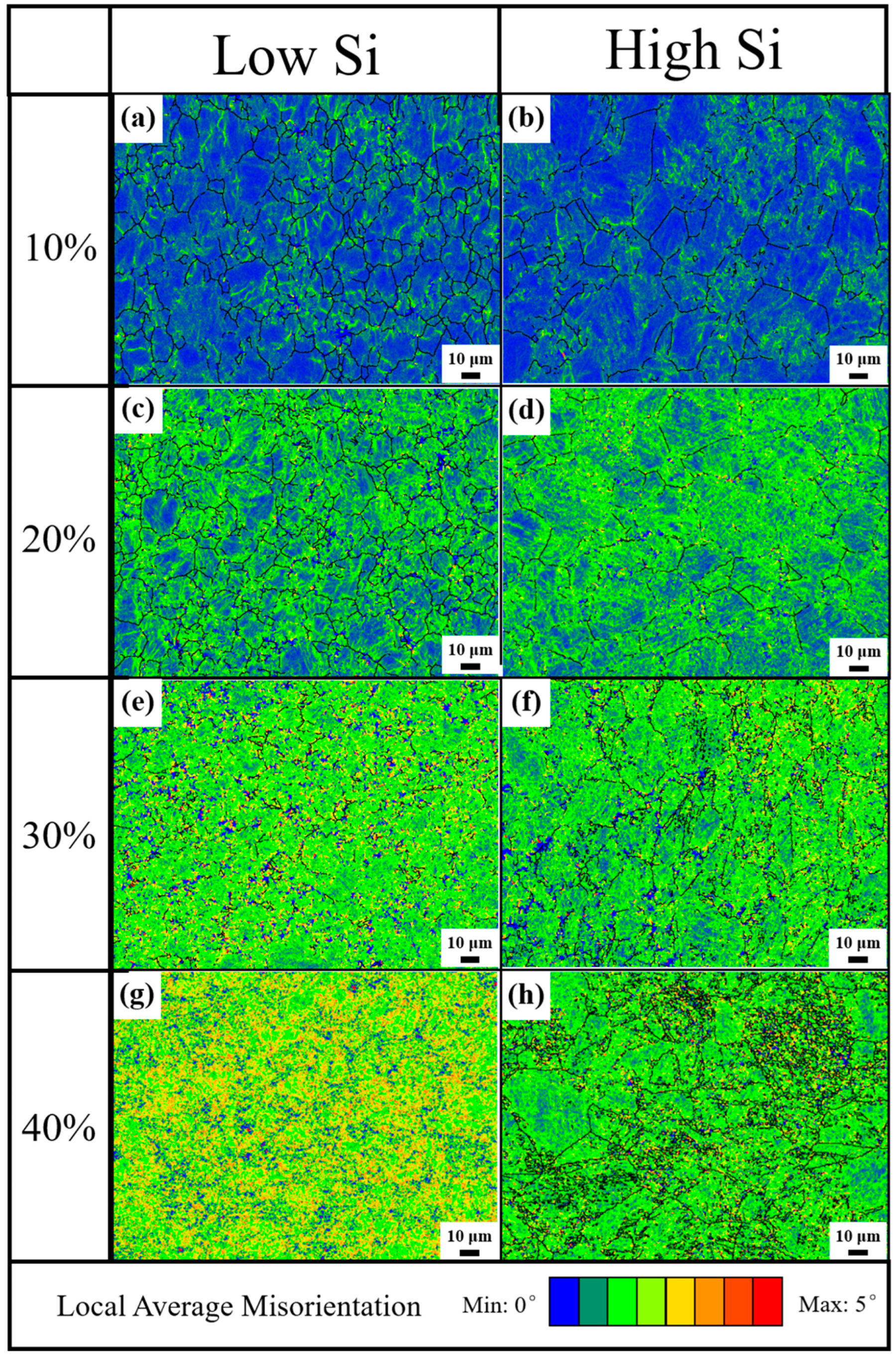
The residual stress magnitude can be qualitatively examined through a stress distribution diagram. Figure 3 illustrates the local average misorientation (LAM) of 301Si-L and 301Si-H under varying deformations. Different colors denote varying stress distribution values: blue signifies a small LAM value, indicating nearly zero residual stress; green and yellow represent high LAM values and relatively elevated residual stresses; while red indicates a very high LAM value, reflecting very high residual stress. This Figure demonstrates that both materials intensify residual stress as deformation increases. Initially, due to non-uniform cold deformation, residual stresses in the microstructure aggregate at certain grain boundaries. As deformation progresses, grain deformation becomes more uniform, and residual stress gradually shifts from some grain boundaries to other grains, leading to a more uniform distribution of residual stress. However, when comparing stress distribution maps of the two types of Si content stainless steel, it is evident that the residual stress of high 301Si-H is significantly lower than that of 301Si-L during extensive deformation, accompanied by a more uniform degree of deformation.
Figure 4a illustrates the distribution of small-angle grain boundaries and high-angle grain boundaries in low silicon 301 austenitic stainless steel at various levels of deformation. Here, LABs denote small-angle grain boundaries with an orientation deviation between adjacent grains of 2–15°; HABs represent high-angle grain boundaries with an orientation discrepancy exceeding 15°; CSL refers to special grain boundaries that are lattice grain boundaries with unique low ∑ coincidence site lattice positions differing from typical large-angle grain boundaries. A considerable increase in small-angle grain boundaries was observed in 301Si-L austenitic stainless steel when deformation surpasses 20%, with a contrasting trend observed for special grain boundaries. Conversely, high-angle grain boundaries remain minimal regardless of deformation extent, with a decreasing pattern noted. In the initial stages of cold deformation, the rotation of the crystal activates multiple slip systems. Lower stacking fault energy can lead to earlier occurrence of dislocation slip. As deformation variables increase, a significant number of dislocations are generated within the structure, making dislocation movement increasingly challenging. The dense stacking of dislocations can result in high stress concentration. Moreover, twinning plays a role during deformation. When stress surpasses the minimum threshold for twinning initiation, twinning can take place within the structure, altering the crystal orientation and easing slip, thereby reducing deformation resistance. Furthermore, as deformation progresses, the prevalence of small-angle grain boundaries rises, special grain boundaries decline, while large angle grain boundaries remain relatively constant.
Figure 4b illustrates the changes in LABs, HABs, and CSL grain boundaries in 301Si-H austenitic stainless steel across a deformation range of 10–40% as the strain increases. The presence of silicon promotes the early development of low-angle grain boundaries during deformation. Moreover, the occurrence of deformation twins significantly rises in the microstructure of high silicon 301 steel, resulting in increased martensite formation throughout the grains under 30% deformation, with martensite being widely distributed. Concerning martensite formation, a lower amount of martensite forms near twinning structures, indicating a direct correlation between martensite formation and the orientation of these twinning crystals during deformation.
Many studies have documented a trend in decreasing stacking fault energy with the addition of silicon to austenitic stainless steel [38,39,40]. Based on the current formula for calculating stacking fault energy [41], the stacking fault energy of the alloy at room temperature is approximately given as follows:
γ S F 300 ( m J m 2 ) = γ S F 0 + 1.59 N i 1.34 M n + 0.06 M n 2 1.75 C r + 0.01 C r 2 + 15.21 M o 5.59 S i 60.69 ( C + 1.2 N ) 1 / 2 + 26.27 ( C + 1.2 N ) × ( C r + M n + M o ) 1 / 2 + 0.61 N i C r + M n 1 / 2
This implies that increasing the silicon content will decrease the stacking fault energy of the alloy when the content of other elements remains approximately constant. Stacking fault energy is a crucial parameter influencing the formation of martensite [42]. It affects the frequency of mechanical twins’ intersection, which serve as nucleation sites for martensite [43]. Furthermore, as Venables reported [44], the stress needed for twinning deformation is proportionally related to the stacking fault energy. Therefore, 301Si-H, with a lower stacking fault energy, easily formed mechanical twins compared to 304Si-L, resulting in a larger amount of martensite in 301Si-H. It can be seen from Figure 4b that the higher deformation may promote the occurrence of deformation twins. Therefore, the ~26.8% increase in the martensite content after 40% cold-rolling in the 301Si-H specimen as opposed to the 30% cold-rolled 301Si-H specimen (Table 2), indicating that the increases in deformation twins is beneficial for the nucleation of martensite.
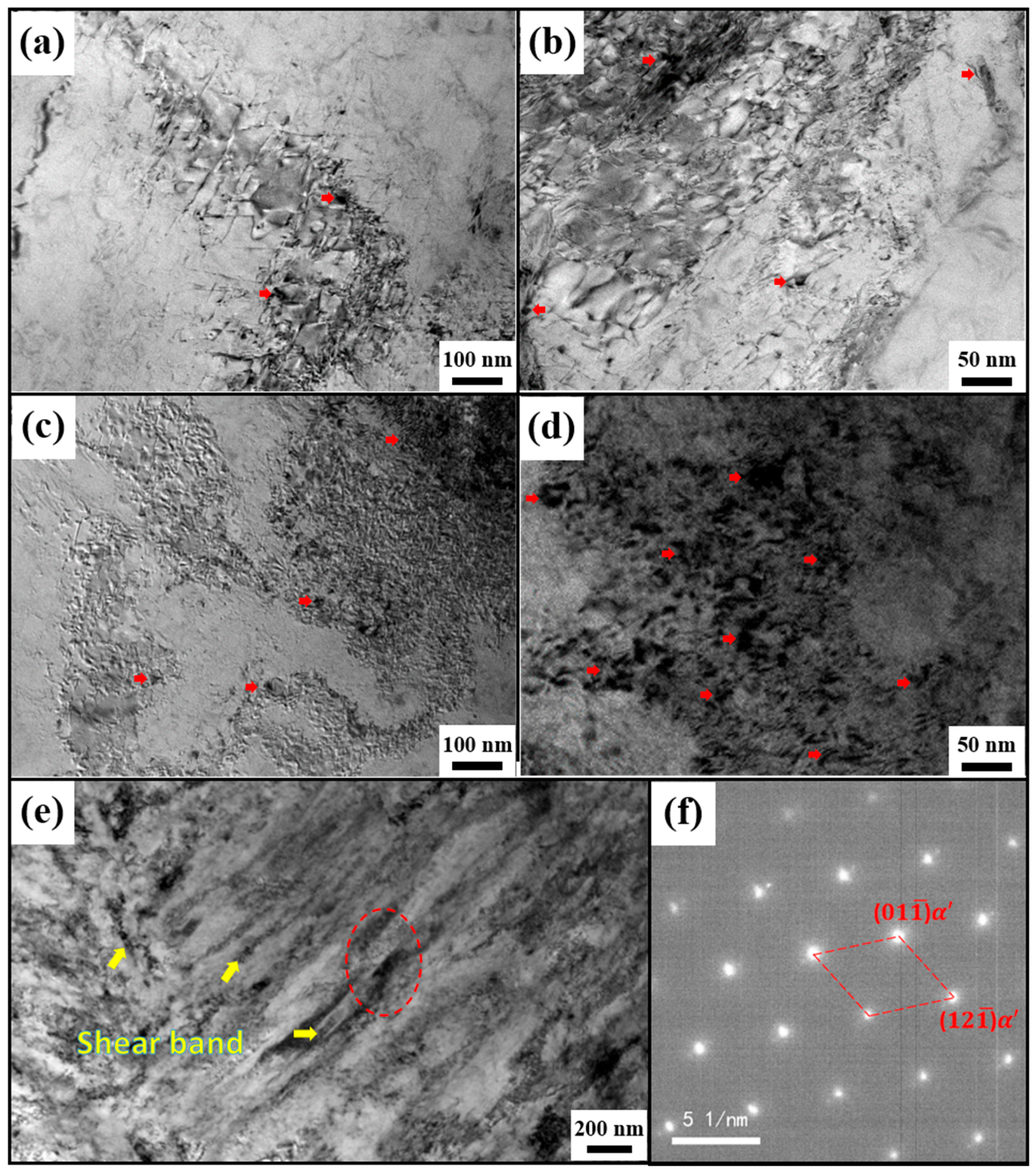
Figure 5 further examined the influence of silicon on martensitic nucleation in low and high silicon specimens using TEM. In the case of the samples at deformation amount of 10% (Figure 5a,c), 301Si-L experiences localized deformation, where defects like dislocations gather in regions with high deformation, whereas 301Si-H undergoes more uniform deformation, with multiple areas experiencing deformation and being dispersed with defects like dislocations. Figure 5b,d display TEM images of 40% deformed specimens. 301Si-L exhibits uneven deformation, where defects like dislocations cluster in high-deformation-rate zones. In contrast, 301Si-H shows uniform deformation across all microstructures, accompanied by the presence of defects such as dislocations and slip bands. Figure 5e illustrates the magnified TEM image of 40%-deformed 304Si-H specimens, where prominent slip bands are clearly visible running parallel to the rolling direction. Figure 5f depicts an electron diffraction pattern observed at a dark location with dislocation and slip bands pile-up circled with a red dashed line in Figure 5e. The pattern reveals parallel features, validating the electron diffraction pattern as a type of martensite structure [35,45], and the transformation to a deformation martensitic phase takes place at the dislocation pile-up site. Further, the dark martensite that was marked with a red arrow in all of the TEM images predominantly emerges near grain boundaries in 301Si-L specimens. On the other hand, martensite emerges both at grain boundaries and within grains in 301Si-H specimens. These findings reaffirm that improving silicon content enhances the count of martensitic nucleation points and facilitates the creation of a more uniform martensitic structure.
Figure 6 displays TEM images of grain boundaries and their surroundings in the 40% cold-deformed 301Si-L sample, along with EDS data. Table 3 presents the content of element at grain and near grain boundaries. An increase in Si content at and near the grain boundaries compared to the sample’s average Si content, with even higher Si content specifically at the grain boundaries. Austenitic stainless steel exhibits low stacking fault energy. This leads to a stacking fault between two incomplete dislocations. The presence of enriched silicon at the grain boundary reduces the width of the stacking fault. This reduction is advantageous, as it promotes the formation of dislocations and enhances the dislocation density at the grain boundary. Such conditions are beneficial for the nucleation of shear deformation in martensite during the deformation process [46,47,48].
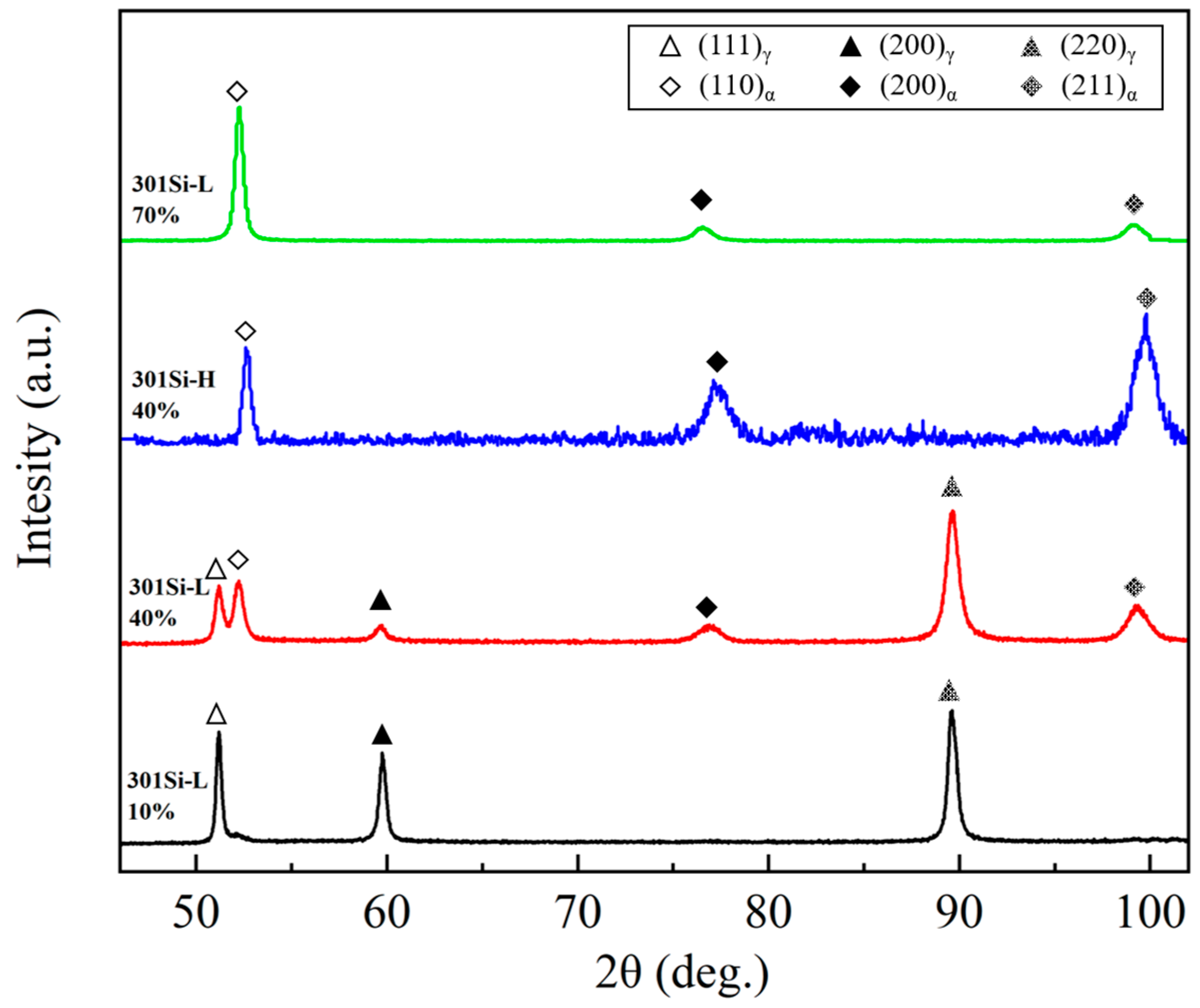
Figure 7 compares the X-ray diffraction patterns of the 301Si-L and 301Si-H after various deformations. The X-ray diffraction pattern of the CR specimen confirmed that cold-rolling led to the transformation of austenite to martensite. In XRD spectra, peaks of (111)γ, (200)γ, and (220)γ represent the austenite phase, while peaks of (110)α′ and (200)α′ indicate the martensite phase. After 10% cold rolling, 301Si-L still retains a strong (111)γ peak, indicating less martensite present in the microstructure. However, after 40% deformation, martensitic phase (110)α′ significantly increases, suggesting deformation promotes the austenite to martensite transformation. In contrast, 301Si-H shows almost no (111)γ peak after 40% cold rolling, with martensitic phase (110)α′ exhibiting significant enhancement, indicating the almost complete transformation from austenite to martensite. XRD analysis results are consistent with the microstructure characterization through EBSD, showing a similar austenite to martensite ratio. Even low-silicon 301Si-L samples exhibit noticeable (110)α′ peak after 70% deformation, with (111)γ nearly disappearing. Therefore, the higher silicon content in 301Si-H achieves almost complete austenite to martensite transformation after 40% deformation, while low-silicon 301Si-L requires 70% cold deformation to achieve full transformation of the austenite, indicating that the addition of silicon can help reduce the deformation amount to achieve austenite transformation.
Figure 8 illustrates the schematic diagram of martensite formation in stainless steel with increasing deformation at various Si contents. Silicon (Si), by reducing the stacking fault energy of austenite, enhances the formation of martensite within the austenitic structure. As the cold-rolling process of 301 metastable austenitic stainless steel progresses at a higher deformation rate, the number and density of slip bands in the deformed structure increase. Due to silicon’s tendency to accumulate near the grain boundaries, there is a more prominent nucleation of martensitic grains from the grain boundary and in the vicinity of the triple grain boundary in 301Si-H compared to 301Si-L during deformation. These grains then propagate either across the entire grain towards the opposite boundary or intersect with existing martensitic grains to impede their growth. This process accelerates the accumulation of martensite content during cold deformation, thereby aiding in the formation of refined reverted austenite in the subsequent martensite–austenite reverse transformation phase. As the strain applied to the specimen increases, martensite not only forms at grain boundaries, but also between shear bands and further extends into austenite grains. Particularly, the increase in deformation twins at a larger deformation is beneficial for the nucleation of martensite. Therefore, compared with low Si samples, the distribution of the martensite phase in high Si samples is more uniform.

4. Conclusions

This study examines the impact of silicon content on the microstructure, martensitic transformation, and stress distribution of 301 stainless steel. The deformation amount significantly influences grain size and martensitic transformation of 301 metastable austenitic stainless steel. A low deformation amount (less than 20%) results in minimal martensite transformation. Conversely, there is a substantial increase in martensite transformation at deformation amounts exceeding 30%. Additionally, higher deformation amounts correlate with increased martensite transformation. The addition of silicon in 301Si steel results in significantly more martensite by decreasing its stacking fault energy. EBSD characterization reveals that martensite initially nucleates at grain boundaries and then grows into grains, with the grain size of the resulting martensite being determined by the original austenite grain size. Silicon promotes martensite formation due to the increase in the dislocation density at the grain boundary caused by Si enrichment. In particular, the increase in Si content promotes the formation of coarse deformation twins during large deformation, and aids in martensite nucleation.

Author Contributions

Conceptualization, methodology, validation, formal analysis, J.L., J.W. and P.H.; software, Y.L.; investigation, J.L. and Y.L.; resources, J.W. and P.H.; data curation, J.L.; writing—original draft, J.L.; writing—review and editing, J.L., J.W. and P.H.; visualization, J.L. and Y.L.; supervision, J.W. and P.H.; project administration, J.W. and P.H.; funding acquisition, J.W. and P.H. All authors have read and agreed to the published version of the manuscript.

Funding

The research was financially supported by the National Natural Science Foundation of China (Grant Nos. 52104338, 51871159).

Data Availability Statement

The data presented in this study are available on request from the corresponding author due to privacy/legal concerns.

Conflicts of Interest

The authors declare no conflicts of interest. Author Jun Li was employed by the company Taiyuan Iron and Steel (Group) Company Ltd. The remaining authors declare that the research was conducted in the absence of any commercial or financial relationships that could be construed as a potential conflict of interest.

References

  1. Srivatsan, S.T.; Manigandan, K. Processing, Characteristics and applications of bulk nanostructured metals and alloys. Curr. Nanomater. 2021, 6, 90–105. [Google Scholar] [CrossRef]
  2. Dehm, G.; Jaya, B.N.; Raghavan, R.; Kirchlechner, C. Overview on micro-and nanomechanical testing: New insights in interface plasticity and fracture at small length scales. Acta Mater. 2018, 142, 248–282. [Google Scholar] [CrossRef]
  3. Stráská, J. Physical Properties of Ultrafine-Grained Magnesium Based Alloys Prepared by Various Severe Plastic Deformation Techniques. Ph.D. Thesis, Charles University, Prague, Czech Republic, 2014. [Google Scholar]
  4. Jebelli, A.A.; Fereshteh-Saniee, F. Superior combined strength and elongation by conducting elevated temperature constrained groove pressing on Al–Mg–Mn sheets. Mater. Chem. Phys. 2023, 307, 128090. [Google Scholar] [CrossRef]
  5. Gupta, R.K.; Birbilis, N. The influence of nanocrystalline structure and processing route on corrosion of stainless steel: A review. Corros. Sci. 2015, 92, 1–15. [Google Scholar] [CrossRef]
  6. Kowalska, J.; Witkowska, M. The Influence of Cold Deformation and Annealing on Texture Changes in Austenitic Stainless Steel. Adv. Sci. Technol. Res. J. 2024, 18, 143–158. [Google Scholar] [CrossRef] [PubMed]
  7. Shahri, M.G.; Hosseini, S.R.; Salehi, M. Formation of nano/ultrafine grains in AISI 321 stainless steel using advanced thermo-mechanical process. Acta Metall. Sin. 2015, 28, 499–504. [Google Scholar] [CrossRef]
  8. Sun, G.S.; Du, L.X.; Hu, J.; Zhang, B.; Misra, R.D.K. On the influence of deformation mechanism during cold and warm rolling on annealing behavior of a 304 stainless steel. Mater. Sci. Eng. A 2019, 746, 341–355. [Google Scholar] [CrossRef]
  9. Järvenpää, A.; Jaskari, M.; Juuti, T.; Karjalainen, P. Demonstrating the effect of precipitation on the mechanical stability of fine-grained austenite in reversion-treated 301LN stainless steel. Metals 2017, 7, 344. [Google Scholar] [CrossRef]
  10. Haušild, P.; Davydov, V.; Drahokoupil, J.; Landa, M.; Pilvin, P. Characterization of strain-induced martensitic transformation in a metastable austenitic stainless steel. Mater. Des. 2010, 31, 1821–1827. [Google Scholar] [CrossRef]
  11. Sohrabi, M.J.; Naghizadeh, M.; Mirzadeh, H. Deformation-induced martensite in austenitic stainless steels: A review. Arch. Civ. Mech. Eng. 2020, 20, 124. [Google Scholar] [CrossRef]
  12. Izuta, Y.; Prasad, K.; Ito, A.; Tanaka, M.; Torizuka, S. Transmission X ray diffraction characterization of deformation induced martensite in 301 and 304 stainless steels rolled at 77K: Role of grain size. Mater. Sci. Eng. A 2020, 794, 139984. [Google Scholar] [CrossRef]
  13. Johannsen, D.L.; Kyrolainen, A.; Ferreira, P.J. Influence of annealing treatment on the formation of nano/submicron grain size AISI 301 austenitic stainless steels. Metall. Mater. Trans. A 2006, 37, 2325–2338. [Google Scholar] [CrossRef]
  14. Misra, R.D.K.; Nayak, S.; Venkatasurya, P.K.C.; Ramuni, V.; Somani, M.C.; Karjalainen, L.P. Nanograined/ultrafine-grained structure and tensile deformation behavior of shear phase reversion-induced 301 austenitic stainless steel. Metall. Mater. Trans. A 2010, 41, 2162–2174. [Google Scholar] [CrossRef]
  15. Eskandari, M.; Kermanpur, A.; Najafizadeh, A. Formation of nano-grained structure in a 301 stainless steel using a repetitive thermo-mechanical treatment. Mater. Lett. 2009, 63, 1442–1444. [Google Scholar] [CrossRef]
  16. Wang, Y.; Hu, Y.X.; Mao, F.; Li, J.; Zhou, J.; Zhang, S.H.; Wei, L.L.; Misra, R.D.K.; Liu, B.; Xu, H.; et al. Microstructure evolution and mechanical properties of bimodal grain sized 301 stainless steel strip induced by reverse phase transformation. J. Mater. Res. Technol. 2022, 17, 2772–2781. [Google Scholar] [CrossRef]
  17. Zhao, L.Y.; Yang, J.W.; Tian, L.; Li, X.L.; Lei, C.S.; Wang, H.F. The Influence of Tempering Parameters on the Microstructure, Mechanical Property, and the Corresponding Strengthening Mechanism of Metastable 301 Austenitic Stainless Steel. Steel Res. Int. 2024, 95, 2300674. [Google Scholar] [CrossRef]
  18. Lü, Y.P.; Hutchinson, B.; Molodov, D.A.; Gottstein, G. Effect of deformation and annealing on the formation and reversion of ε-martensite in an Fe–Mn–C alloy. Acta Mater. 2010, 58, 3079–3090. [Google Scholar] [CrossRef]
  19. Sohrabi, M.J.; Mirzadeh, H.; Dehghanian, C. Thermodynamics basis of saturation of martensite content during reversion annealing of cold rolled metastable austenitic steel. Vacuum 2020, 174, 109220. [Google Scholar] [CrossRef]
  20. Shakhova, I.; Dudko, V.; Belyakov, A.; Tsuzaki, K.; Kaibyshev, R. Effect of large strain cold rolling and subsequent annealing on microstructure and mechanical properties of an austenitic stainless steel. Mater. Sci. Eng. A 2012, 545, 176–186. [Google Scholar] [CrossRef]
  21. Sotniczuk, A.; Kuczyńska-Zemła, D.; Królikowski, A.; Garbacz, H. Enhancement of the corrosion resistance and mechanical properties of nanocrystalline titanium by low-temperature annealing. Corros. Sci. 2019, 147, 342–349. [Google Scholar] [CrossRef]
  22. Ahmedabadi, P.M.; Kain, V.; Dangi, B.K.; Samajdar, I. Role of grain boundary nature and residual strain in controlling sensitisation of type 304 stainless steel. Corros. Sci. 2013, 66, 242–255. [Google Scholar] [CrossRef]
  23. Jones, R.; Randle, V. Sensitisation behaviour of grain boundary engineered austenitic stainless steel. Mater. Sci. Eng. A 2010, 527, 4275–4280. [Google Scholar] [CrossRef]
  24. Fang, X.Y.; Zhang, K.; Guo, H.; Wang, W.G.; Zhou, B.X. Twin-induced grain boundary engineering in 304 stainless steel. Mater. Sci. Eng. A 2008, 487, 7–13. [Google Scholar] [CrossRef]
  25. Tsuchida, N.; Ishimaru, E.; Kawa, M. Role of Deformation-Induced Martensite in TRIP Effect of Metastable Austenitic Steels. ISIJ Int. 2021, 61, 556–563. [Google Scholar] [CrossRef]
  26. Panov, D.; Pertsev, A.; Smirnov, A.; Khotinov, V.; Simonov, Y. Metastable austenitic steel structure and mechanical properties evolution in the process of cold radial forging. Materials 2019, 12, 2058. [Google Scholar] [CrossRef] [PubMed]
  27. Dastur, P.; Zarei-Hanzaki, A.; Pishbin, M.H.; Moallemi, M.; Abedi, H.R. Transformation and twinning induced plasticity in an advanced high Mn austenitic steel processed by martensite reversion treatment. Mater. Sci. Eng. A 2017, 696, 511–519. [Google Scholar] [CrossRef]
  28. Naghizadeh, M.; Mirzadeh, H. Microstructural evolutions during annealing of plastically deformed AISI 304 austenitic stainless steel: Martensite reversion, grain refinement, recrystallization, and grain growth. Metall. Mater. Trans. A 2016, 47, 4210–4216. [Google Scholar] [CrossRef]
  29. Chattopadhyay, S.; Anand, G.; Chowdhury, S.G.; Manna, I. Effect of reverse austenitic transformation on mechanical property and associated texture evolution in AISI 316 austenitic stainless steel processed by low temperature rolling and annealing. Mater. Sci. Eng. A 2018, 734, 139–148. [Google Scholar] [CrossRef]
  30. Okayasu, M.; Tomida, S. Phase transformation system of austenitic stainless steels obtained by permanent compressive strain. Mater. Sci. Eng. A 2017, 684, 712–725. [Google Scholar] [CrossRef]
  31. Somani, M.; Karjalainen, L.P.; Kyröläinen, A.; Taulavuori, T. Processing of Submicron Grained Microstructures and Enhanced Mechanical Properties by Cold-Rolling and Reversion Annealing of Metastable Austenitic Stainless Steels. Mater. Sci. Forum 2007, 539–543, 4875–4880. [Google Scholar] [CrossRef]
  32. Li, D.J.; Feng, Y.R.; Song, S.Y.; Liu, Q.; Bai, Q.; Ren, F.Z.; Shangguan, F.S. Influences of silicon on the work hardening behavior and hot deformation behavior of Fe–25 wt%Mn–(Si, Al) TWIP steel. J. Alloys Compd. 2015, 618, 768–775. [Google Scholar] [CrossRef]
  33. Takemoto, T.; Murata, Y.; Tanaka, T. Effects of Alloying Elements and Thermomechanical Treatments on Mechanical and Magnetic Properties of Cr-Ni Austenitic Stainless Steel. ISIJ Int. 1990, 30, 608–614. [Google Scholar] [CrossRef]
  34. Li, Y.J.; Li, J.; Ma, J.Y.; Han, P.D. Influence of Si on strain-induced martensitic transformation in metastable austenitic stainless steel. Mater. Today Commun. 2022, 31, 103577. [Google Scholar] [CrossRef]
  35. Yang, M.; Lei, L.; You, Y.F.; Wang, P.Z.; Xu, F.H.; Zhao, F.; Liang, Y.L. Enhanced strength-plasticity synergy of 304 stainless steel by introducing gradient nanograined single austenite phase structure via USRP and induction annealing. Mater. Des. 2024, 244, 113123. [Google Scholar] [CrossRef]
  36. Liu, X.B.; Zhou, M.C.; Zhang, X.F. Ultra-flash annealing constructed heterogeneous austenitic stainless steel with excellent strength-ductility. Mater. Charact. 2022, 192, 112182. [Google Scholar] [CrossRef]
  37. Liu, J.B.; Chen, C.X.; Feng, Q.; Fang, X.Y.; Wang, H.T.; Liu, F.; Lu, J.; Raabe, D. Dislocation activities at the martensite phase transformation interface in metastable austenitic stainless steel. Mater. Sci. Eng. A 2017, 703, 236–243. [Google Scholar] [CrossRef]
  38. Lehnhoff, G.R.; Findley, K.O.; De Cooman, B.C. The influence of silicon and aluminum alloying on the lattice parameter and stacking fault energy of austenitic steel. Scr. Mater. 2014, 92, 19–22. [Google Scholar] [CrossRef]
  39. Jo, Y.H.; Yang, J.; Choi, W.M.; Doh, K.Y.; Lee, D.; Kim, H.S.; Lee, B.J.; Sohn, S.S.; Lee, S. Body-centered-cubic martensite and the role on room-temperature tensile properties in Si-added SiVCrMnFeCo high-entropy alloys. J. Mater. Sci. Technol. 2021, 76, 222–230. [Google Scholar] [CrossRef]
  40. Lehnhoff, G.R.; Findley, K.O. The Martensitic Transformation and Strain-Hardening Behavior of Austenitic Steels During Fatigue and Tensile Loading. JOM 2014, 66, 756–764. [Google Scholar] [CrossRef]
  41. Dai, Q.X.; Wang, A.D.; Cheng, X.D.; Luo, X.M. Stacking fault energy of cryogenic austenitic steels. Chin. Phys. 2002, 11, 596–600. [Google Scholar]
  42. Bracke, L.; Mertens, G.; Penning, J.; De Cooman, B.C.; Liebeherr, M.; Akdut, N. Influence of Phase Transformations on the Mechanical Properties of High-strength Austenitic Fe-Mn-Cr Steel. Metall. Mater. Trans. A 2006, 37, 307–317. [Google Scholar] [CrossRef]
  43. Choi, J.Y.; Jin, W. Strain Induced Martensite Formation and Its Effect on Strain Hardening Behavior in the Cold Drawn 304 Austenitic Stainless Steel. Scr. Mater. 1997, 36, 99–104. [Google Scholar] [CrossRef]
  44. Venables, J.A. The Nucleation and Propagation of Deformation Twins. J. Phys. Chem. Solids 1964, 25, 693–700. [Google Scholar] [CrossRef]
  45. He, Y.S.; Zhou, H.Y.; Liu, W.; Duan, F.M.; Shin, K.; Zhao, Y.C.; Zheng, W.Y. The role of α′-martensite on the variation of compressive residual stress in a gradient nanostructured austenitic stainless steel. Mater. Des. 2024, 238, 112723. [Google Scholar] [CrossRef]
  46. Shokohfar, A.; Abbasi, S.M.; Yazdani, A.; Rabiee, B. Application of Thermo-Mechanical Process to Achieve Nanostructure in 301 Austenitic Stainless Steels. Defect Diffus. Forum 2011, 312–315, 51–55. [Google Scholar] [CrossRef]
  47. Li, Z.J.; Chen, L.; Fu, P.X.; Su, H.H.; Dai, P.Q.; Tang, Q.H. The effect of Si addition on the heterogeneous grain structure and mechanical properties of CrCoNi medium entropy alloy. Mater. Sci. Eng. A 2022, 852, 143655. [Google Scholar] [CrossRef]
  48. Li, Z.J.; Ding, X.K.; Chen, L.; He, J.C.; Chen, J.F.; Chen, J.; Hua, N.B.; Dai, P.Q.; Tang, Q.H. Effect of Si content and annealing temperatures on microstructure, tensile properties of FeCoCrNiMn high entropy alloys. J. Alloys Compd. 2023, 935, 168090. [Google Scholar] [CrossRef]
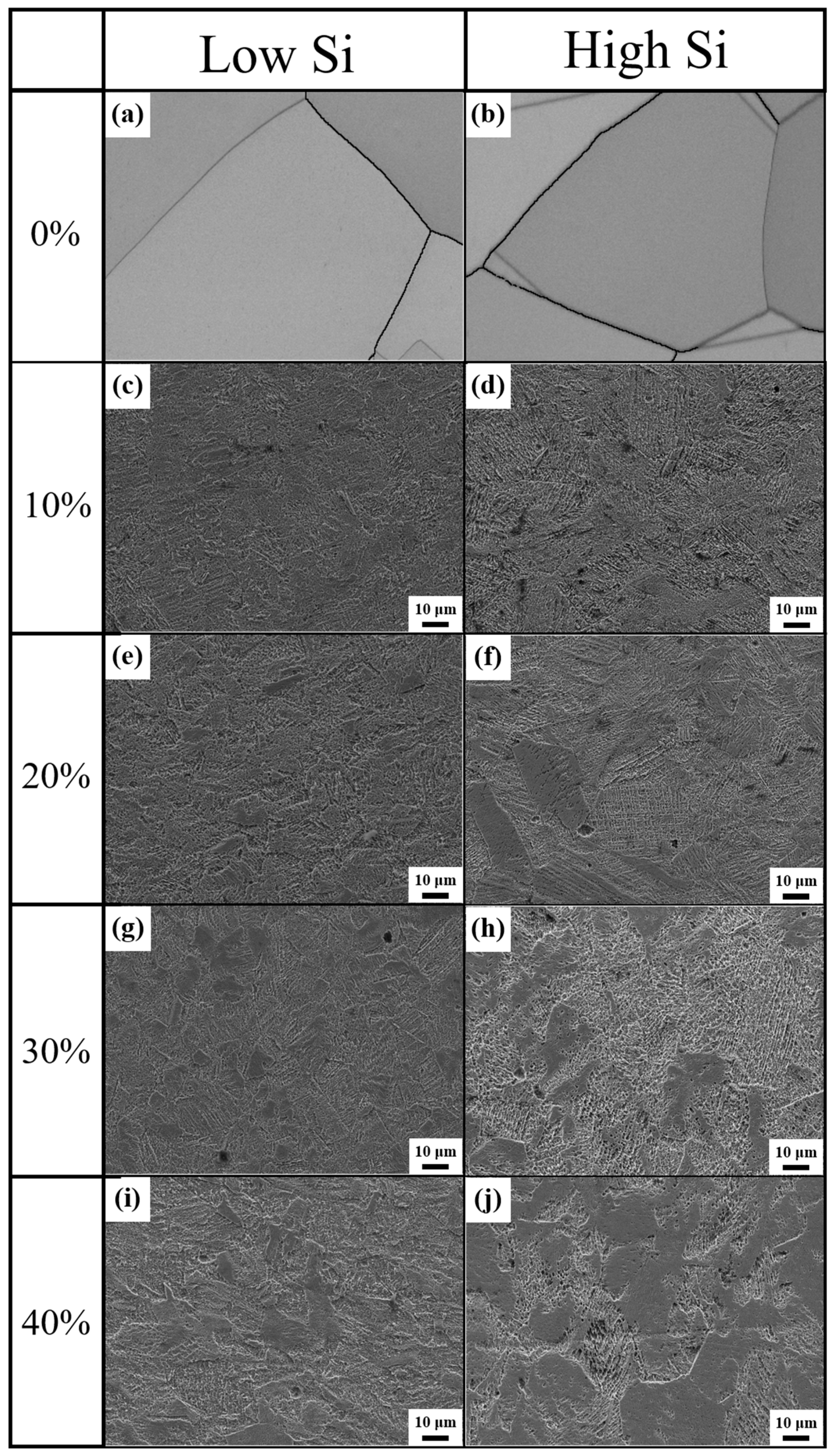
Figure 1. SEM image of 301Si-L (a,c,e,g,i) and 301Si-H (b,d,f,h,j) samples after different levels of cold-rolling deformations: (a,b) without cold rolling, (c,d) 10%, (e,f) 20%, (g,h) 30%, and (i,j) 40%.
Metals 14 00827 g001
Figure 2. The phase distribution diagrams of 301Si-L (a,c,e,g) and 301Si-H (b,d,f,h) samples under different deformations: (a,b) 10%, (c,d) 20%, (e,f) 30%, and (g,h) 40%. And the BC (Band Contrast) diagram corresponding to the phase distribution diagram is marked with the number 1 after the corresponding letter.
Metals 14 00827 g002
Figure 3. Local average misorientation (LAM) map of 301Si-L (a,c,e,g) and 301Si-H (b,d,f,h) samples after different levels of cold-rolling deformations: (a,b) 10%, (c,d) 20%, (e,f) 30%, and (g,h) 40%.
Metals 14 00827 g003
Figure 4. Proportion of different types of grain boundaries in the microstructure of the sample: (a) 301Si-L; (b) 301Si-H.
Metals 14 00827 g004
Figure 5. TEM microstructure of 301Si-L (a,b) and 301Si-H (ce) under different deformations: (a,c) 10%; (b,d,e) 40%; (f) electron diffraction pattern observed at a dark location circled with a red dashed line in Figure 5e. The dark martensite that was marked with a red arrow.
Metals 14 00827 g005
Figure 6. TEM images (a) and EDS data (b) of grain boundaries and their surroundings in 301Si-L samples with 40% cold deformation. The dark martensite that was marked with a red arrow.
Metals 14 00827 g006
Figure 7. The XRD of the 301Si-L and 301Si-H after various deformations.
Metals 14 00827 g007
Figure 8. Schematic diagram of martensitic transformation during deformation of 301Si-L and 301Si-H stainless steel with increasing deformation amounts.
Metals 14 00827 g008
Table 1. Chemical composition of AISI 301 stainless steel sample used in the experiment (wt.%).
SampleCSiMnNiCrTiVMoCuPS
301Si-L0.160.581.057.5916.910.330.080.050.070.0450.002
301Si-H0.151.411.277.1917.440.330.060.060.080.0390.002
Table 2. The detailed content values of martensite and austenite for both materials under varying deformation levels.
Sample/Phase ContentAusteniteMartensite
L1086.9%13.1%
L2081.7%18.3%
L3057.5%42.5%
L4050.7%49.3%
H1073.0%27.0%
H2065.4%34.6%
H3036.5%63.5%
H409.7%90.3%
Table 3. The content of element at grain and near grain boundaries.
SiCrNiFe
GB1.0217.705.7874.16
near GB0.9317.545.5774.43
Disclaimer/Publisher’s Note: The statements, opinions and data contained in all publications are solely those of the individual author(s) and contributor(s) and not of MDPI and/or the editor(s). MDPI and/or the editor(s) disclaim responsibility for any injury to people or property resulting from any ideas, methods, instructions or products referred to in the content.