Article

A Case Study of a Laser Beam Welding Model for the Welding of Inconel 718 Sheets of a Dissimilar Thickness

by
Oihane Murua
1,
Jon Iñaki Arrizubieta
1,*,
Aitzol Lamikiz
1 and
Heinz Ingo Schneider
2
1
Department of Mechanical Engineering, University of the Basque Country UPV/EHU, Plaza Torres Quevedo 1, 48013 Bilbao, Spain
2
Siemens AG DI MC AMF, Freyeslebenstraße 1, 91058 Erlangen, Germany
*
Author to whom correspondence should be addressed.
Metals 2024, 14(7), 829; https://doi.org/10.3390/met14070829
Submission received: 25 June 2024 / Revised: 12 July 2024 / Accepted: 17 July 2024 / Published: 19 July 2024
(This article belongs to the Special Issue Numerical Simulation of Metals Welding Process—2nd Edition)

Abstract

:
Laser beam welding (LBW) is a highly demanded process for premium-quality joints in aeronautic, energy, or industrial sectors, where flexibility and low-heat-affected zones are required. One of the main applications of LBW in the near future is expected to be the welding of new turbine engine components, which are typically made of Nickel-based superalloys. However, parameter setup is time- and resource-consuming, where experiment-based methods are typically employed. Therefore, the process development is far from an efficient resource utilization. In the present work, an LBW numerical model is developed and experimentally validated through a machine-integrated monitoring system. The LBW model is based on solving the heat transfer problem produced by the laser and provides the resulting temperature field, as well as the weld bead dimensions. The model includes a variable heat source that automatically adapts to the welding regime, conduction, or keyhole. For the model validation, two Inconel 718 sheets of different thicknesses are butt-welded and an error of around 10% is obtained, which ensures the validity of the model.

1. Introduction

Welding is the most important joining technology in the current manufacturing industry, having different heat sources applicable such as the gas tungsten arc, the electron beam, or the laser beam [1]. However, still today, the mechanical properties along the weld bead are the main challenge, and choosing the correct welding heat source is mandatory. For instance, the wide heat-affected zone produced by the gas tungsten arc welding process (GTAW) can be avoided by employing a higher-energy-density heat source such as a laser beam [2]. Therefore, laser beam welding (LBW) is a continuously growing technology thanks to not only the low distortion and high penetration it offers, but also due to the resulting high-quality joints [3]. The development of high-power lasers has enabled the switching from conduction to keyhole welding, and LBW has become a potential manufacturing technique for aerospace parts like turbine engine components [4].
The aerospace industry is focused on developing high-performance components able to keep their mechanical properties at a wide temperature range. The good weldability and exceptional thermomechanical characteristics of the Nickel-based superalloy Inconel 718 make it one of the most employed materials [5]. Nevertheless, considering the solidification cracking of Inconel 718 as one of the most typical failures, the thermal field inspection during the part manufacturing is required for increasing the robustness of the process and avoiding their apparition [6]. Thermal management during the manufacturing process is thereby essential for ensuring appropriate mechanical behavior during the full life cycle of the components. Nonetheless, experimental testing is neither trivial nor efficient today, and process simulation has posed as an efficient tool for saving time and resources.
However, the LBW modeling is still challenging due to the complexity of the ongoing physical phenomena. Several studies have focused on developing thermal models for LBW without being able to predict the welding mechanism and simultaneously adapt the heat source [7,8]. Hence, in most of the models, the welding mode needs to be pre-established in order to introduce the laser heat appropriately. For instance, Shehryar Khan et al. developed a model where the laser energy source was previously defined depending on the focus distance. Likewise, the optimum focus distance for defect-free welds was determined and experimentally validated, although the thermal distribution has to be known in advance [9]. Models able to determine the optimum welding parameters are key for time and resource savings. Thus, Thejasree et al. developed an application of the ANFIS-Java algorithm to optimize the LBW parameters for Inconel 718. However, this kind of model still needs further investigations because if the material changes, the full characterization must be redeveloped [10].
Zhang et al. developed a numerical model including the melt pool dynamics, although the heat input was determined by the user before being experimentally calibrated for each situation [8]. In more recent research, Lorin et al. developed a heat source model by combining a Gaussian heat source and an upside-down cone. Promising results were obtained and the keyhole phenomenon was successfully modeled. However, they have to develop heuristic functions for evaluating the welding parameters and the heat source settings in each case. Thus, further investigation is needed for obtaining an automatically adaptable heat source [11]. Another approach of hybrid heat source simulations was performed by Lorin et al. and included the keyhole dynamics. Nonetheless, just the keyhole regime was considered [12]. When keyhole welding is modeled, introducing the heat source in the plate may be a complex task once the material vaporization starts, and therefore Faraji et al. developed a keyhole laser welding model with a heat source constructed by a conical volumetric heat source in the upper side and a cylindrical volumetric heat source in the lower side of the welded part. Despite validating the keyhole simulations, before developing the model, extended experimental calibration needs to be performed [13].
Considering the complex physical phenomenon taking place during the laser welding process, several studies are found where the employed models focus only on a small area of the joining process in order to save simulation costs. For instance, as the melt pool dynamics are the cause of the weld bead formation, local simulations have been developed where the movement of the molten material is included. Duggirala et al. also centered their model in evaluating the impact of the Marangoni flow in the weld pool dimensions [14]. Chianese et al. developed a multiphase CFD model for simulating copper-to-steel welding [15]. Another example of this type of modeling approach is the work presented by Ke et al., who included an oscillating laser beam and studied its influence in the welding regime: the keyhole, transition, and conduction [16]. Nevertheless, such CFD simulations are extremely time-consuming, and they typically have size and geometry restrictions. Furthermore, Feng et al. studied the melt pool movement modeling in LBW and concluded that for stable welding conditions, regular clads are obtained and such a phenomenon can be considered as constant. This point eases their simulation, as it opens the door to their inclusion through constant factors [17].
Another aspect that limits the applicability of the developed models to real welding processes is their scalability, because most of the time, the studies are accomplished with minimum geometries in order to reduce the computational cost. For instance, Shehryar Khan et al. developed a highly complex model, but with a limited geometrical size (4 × 4 × 1 mm3) so as to obtain results in a reasonable time [9]. Even in the latest models, the complex phenomena like the keyhole dynamics are not simulated in the full domain due to their elevated computational cost [18].
Moreover, most of the LBW models are validated only for sheets of the same thickness in butt weld configuration. Thus, there are few studies where the joining of different thickness plates is included. One of the few examples is an electron beam welding (EBW) model able to predict the thermal behavior during the welding of dissimilar-thickness parts of Zircaloy-4, and good correlation with the experimental results was obtained [19]. For the LBW process, Li et al. presented an experimental study, in which the depth reached during the welding of Ti6Al4V sheets was determined by evaluating the measured thermal field through thermocouples [20]. Hence, there are uncertainties about the thermal management of dissimilar-thickness part welding and further study is needed in this field.
In parallel to the simulations, for ensuring a good control of the LBW process and a final high-joining quality, monitoring systems are required [3], which at the same time provide the required data for the model validation. In a machine-integrated monitoring system, a coaxial camera to the laser is usually employed for the melt pool dimension monitoring [21]. Additionally, the temperature field evaluation is crucial to assess the quality and welding mechanism. For such purposes, two-color pyrometers are frequently used [22].
In light of the limitations of the state of the art, in this research, the case study of a thermal model for the LBW process for dissimilar-thickness plate joining is experimentally validated through a machine-integrated monitoring system and the corresponding metallographic procedure. The developed model is able to automatically adapt the heat source depending on the welding regime and predict the resulting temperature field as well as the weld bead dimensions.

2. Materials and Equipment

The Nickel-based superalloy Inconel 718 plates employed in the experimental validations are supplied by Hayness International (Kokomo, Indiana) with the chemical composition listed in Table 1. Inconel 718 is typically employed for aeronautical applications, where the welding of dissimilar-thickness plates is a common operation in components such as the turbine rear structure.
The two welded plates are 100 × 10 mm in size, with thicknesses of 1.27 mm and 2 mm, respectively. These sheets are butt-welded along the longest side of the plates, where a 100 mm weld is performed. The thermophysical properties of Inconel 718 applied for the model resolution are listed in Table 2.
For the LBW experimental tests, a fiber Yb:YAG solid-state laser from Coherent with a maximum power of 1 kW in CW is used. The laser beam is guided through a 100 μm optical fiber and focused at a 200 mm focal distance, having a 1 mm diameter at the focal position (Ølaser). The welding head is mounted on a five-axis laser machine center and the upper and lower faces of the plates are protected by two Argon 2X gas inlets with 99.99% purity supplied by Nippon Gases (Tokyo, Japan). A total gas flow of 15 L·min−1 is employed. The setup followed during the LBW tests is shown in Figure 1.

3. Model Basis

The thermal model is accomplished by means of the Partial Derivative Equation (PDE) Toolbox of the commercial software Matlab R2023a. The same toolbox is employed for generating the mesh over the entire domain, solving the heat transfer equations, and representing the obtained results.
In accordance with the standard ISO/TS 18166:2016, the simulation implicative assumptions, the thermal model characteristics, the initial and the boundary conditions, and the employed mesh are described in this section [24]. The material properties required for the welding process simulation are detailed in the previous section, Section 2.

3.1. Assumptions

For simulating the LBW process, a series of simplifying hypotheses are considered due to the process complexity. These assumptions are registered below:
  • The material properties are temperature-dependent; see Table 2.
  • The material is isotropic and homogeneous; it is therefore continuous.
  • In order to reduce the computational cost during the simulations, the melt pool dynamics are neglected. As Feng et al. stated, in a stable welding regime, the melt pool dynamics can be defined as constant [18]. Furthermore, Li et al. concluded that despite omitting the melt pool dynamics in an LBW model, it is feasible to predict accurately the melt pool temperatures and weld dimensions [20].
  • The Inconel 718 absorptivity is established to be 0.4 for conduction welding, although this value is increased up to 1 for modeling the internal reflections of the material during the keyhole welding due to the augmented energy transfer efficiency [25].

3.2. Thermal Model

The heat transfer problem is solved with the Fourier’s law, which rules the heat conduction law and implies that the rate of heat transfer through the material is proportional to the negative gradient of the temperature. This law is represented in Equation (1), where k is the thermal conductivity of the material, T = T({u},t) is the temperature distribution, and q = q({u},t) is the heat flux at a given position, {u} = {x y z}, and time step t.
q ( { u } , t ) = k · T ( { u } , t )
For the transient thermal problem resolution, the first equation of thermodynamics must be followed, Equation (2), where ρ is the material density, Cp is the specific heat, k is the thermal conductivity, T is the temperature, and f is the overall heat input.
ρ ( t ) · C p ( t ) · T ( { u } , t ) t · k ( t ) · T ( { u } , t ) = f ( { u } , t )
In order to ensure the convergence and stability of the results, a 1 ms time step, Δt, is employed in the present study. In Equation (2), the term f includes both the laser energy, f l a s e r , and convection and radiation losses, f l o s s e s , as shown in Equation (3). These values are specified in the next section, Section 3.3, where the heat source for conduction and keyhole welding regimes are also differentiated.
f u , t = f l a s e r u , t + f l o s s e s u , t

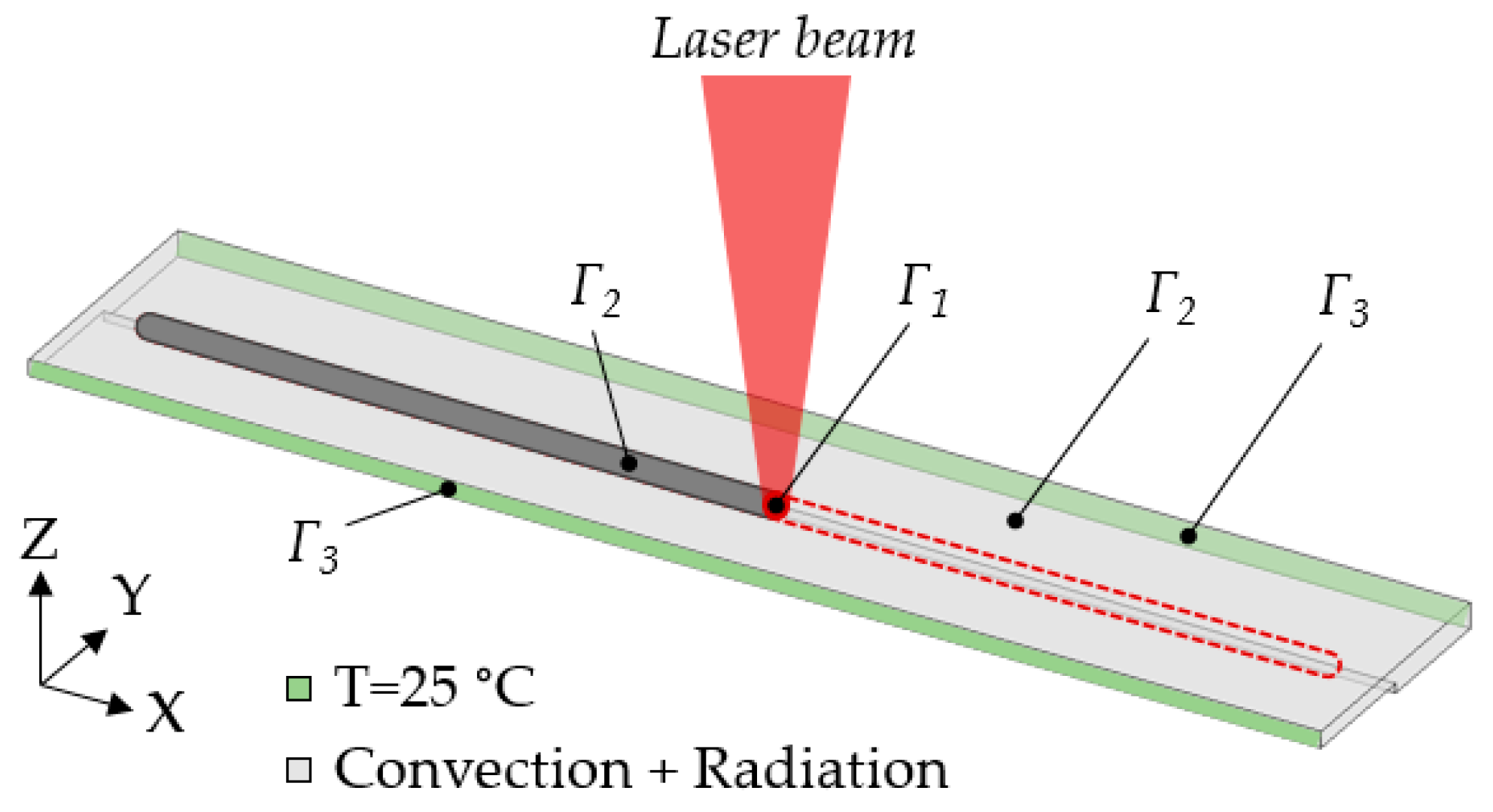
3.3. Initial and Boundary Conditions

The initial temperature condition of the workpiece is set at 25 °C in the full domain, this being the room temperature (Troom), Equation (4). Before the tests, this temperature value was measured experimentally using K-type thermocouples. For the second step and onwards, the model is initialized with the temperature field obtained in the previous step, Equation (5).
T ( { u } , t = 0 ) = T r o o m
T ( { u } , t + Δ t ) = T ( { u } , t )
The boundary conditions (BCs) are divided into three regions, which are represented in Figure 2.
Firstly, the laser heat source is defined as a top-hat energy distribution, which corresponds to the laser employed for the experimental tests. The heat source distribution at the focal plane is presented in Equation (6), where α(T) is the temperature-dependent absorptivity, P(t) is the time-dependent laser power, and R is the laser beam radius.
f l a s e r u , t = α T · P ( t ) π · R 2   Γ 1
The heat is introduced in the welding plate depending on the welding mode or regime, as represented in Figure 3. The welding regime is determined by the maximum temperature reached at the melt pool. If the vaporization temperature is not reached during the welding process, the surface where the laser beam irradiates the material is considered as flat, Figure 3a, and the heat introduced into the system is modeled by Equation (5). On the contrary, if the material is vaporized, the overpressure generated by the vapor displaces the molten material, which allows the laser beam to penetrate the material and generate the keyhole. In this second situation, which is represented in Figure 3b, the laser beam is absorbed by the interface area, A, between the liquid and vapor phases and absorptivity is increased until the unit value; see Equation (7).
f l a s e r u , t = P ( t ) A   Γ 1
The second BC expresses the convection and radiation heat losses in all external faces that are not in contact with the clamping device; see Equation (8). For such calculation, the convection coefficient (hc) and radiative emittance (ε) are defined as 10 W·m−2 and 0.4, respectively, and the Stefan–Boltzmann constant (σ) has a value of 5.67 × 10⁸ W·m−2 K−4.
f l o s s e s u , t = h c · T u , t T r o o m ε · σ · T u , t 4 T r o o m 4   Γ 2
The last BC represents the thermal interaction between the clamping device and the plates. Therefore, it is assumed that during the welding process, this contact area, defined as Γ 3 , is maintained at a constant room temperature (25 °C) due to the high thermal inertia of the clamping device.

3.4. Geometry and Employed Mesh

In Figure 4, the simulated whole geometry is shown, where the clamped sides are indicated, and the weld joint is highlighted by a dashed red line. An adaptive mesh with linear elements is employed in the simulations, with a minimum element size of 0.2 mm and a maximum of 1 mm in the regions far from the weld bead. The mesh is compounded by 299,187 elements and 58,705 nodes.

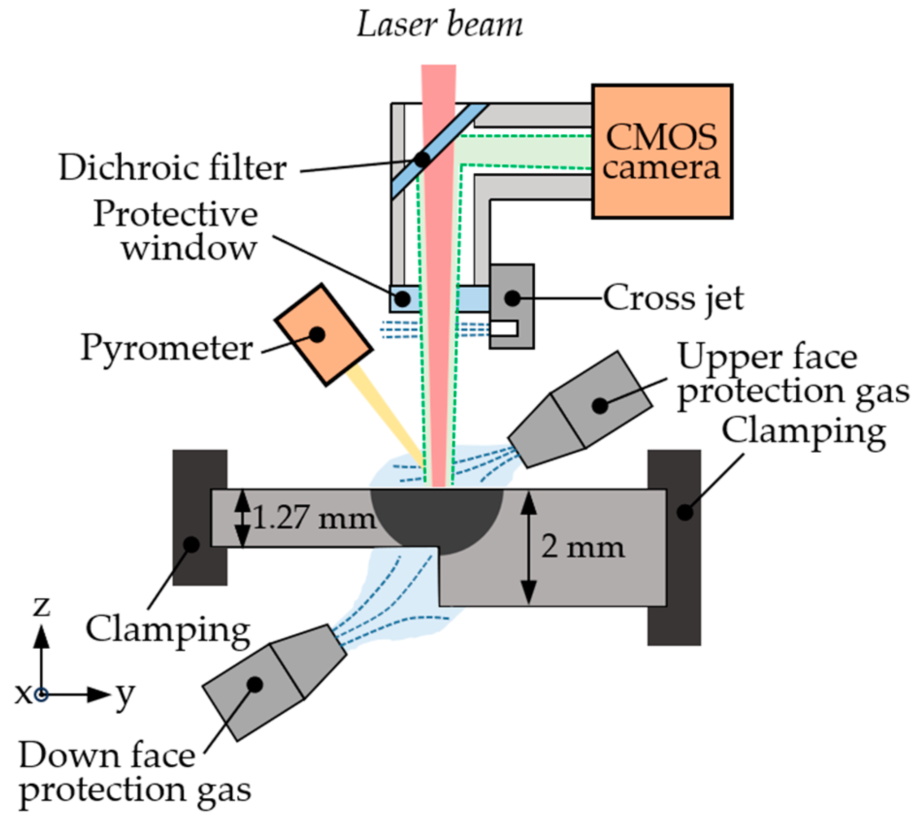
4. Monitoring System

The machine-integrated monitoring system is built by a two-color pyrometer, as shown in the following experimental tests set up in Figure 5. For efficient monitored data management, the collected information is simultaneously extracted from the process.
The temperature measurements are performed by the non-contact two-color pyrometer IGAR 12-LO. This pyrometer has a measuring range between 500 and 2500 °C and is mounted off-axis in order to measure the temperature at a 2 mm distance at the back from the melt pool. The reason for not measuring the maximum temperature directly at the melt pool center is that the welding regime is unknown prior to the tests. Hence, in keyhole welding, the material vaporization would interfere with the measurements and a signal overload would be obtained.

5. Results

The model validation is accomplished, on the one hand, by evaluating the temperature field of the plates with the monitored results. On the other hand, the modeled weld bead dimensions are compared with the metallography results. The simulation and experimental tests carried out are listed in Table 3, in which the parameters employed in each case are detailed.

5.1. Temperature Field Validation

During the experimental tests, the measured temperatures are within the measuring range of the pyrometer and a stable signal is obtained for both tests. In Figure 6, the raw data obtained during the experimental tests are represented. Despite the noise in the signals, stable values are obtained, which goes in line with the hypothesis that under a proper setup, a stable welding is obtained.
The temperature measurements acquired during the LBW process have been averaged in the experimental, TPyrometer, and simulated, TModel, cases to ease the comparison and define the error value, E. To summarize, the obtained results are listed in Table 4.
The numerical values of the temperature measured with the pyrometer and afterwards validated with the model simulation show a maximum error below 1.50%. During the simulations, the temperature field performs as follows (Figure 7), where the pyrometer measuring area is displayed with a black circle. The welding test is performed in the X+ direction.
In addition, with the simulation thermal field results, the weld bead asymmetry is confirmed (Figure 8). The reason for this asymmetry is the dissimilar thickness of the plates, in which a thicker sheet presents higher diffusivity and hence, lower temperatures are obtained.
In Figure 9, the transversal and longitudinal cross-sections of the welds for tests 1 and 2 are shown. In both cases, the transversal cross-section is obtained in the center of the laser beam, which is the reason for not presenting the maximum depth of the weld bead. The limits of the melt pool are also represented in Figure 8 by means of a dark blue line.

5.2. Weld Bead Dimension Validation

Once the metallography inspection is accomplished, the weld bead width (W) and depth (D) are measured experimentally, WExp and DExp, and are compared with the modeled values, WModel and DModel. Such values are listed in Table 5, in which the error (E) between both modeled and measured values is shown. For each test, three cross-sections have been extracted and the average dimensions are presented. For the 100 mm length weld track, the sections are situated at 20, 50, and 80 mm distances from the initial point.
The stable behavior of the welding process results in an almost negligible result dispersion; this is the reason for not providing deviation values for the individual measurements. The same procedure has been employed for the model results, where the dimensions of three sections have been averaged.
The resultant depth and width error values show how the model is able to effectively predict the weld bead dimensions with a maximum error below 13%. The numerical weld bead dimensions according to the input parameters can determine that test 1 is welded in a keyhole regime, while test 2 is welded in the transient regime. As an example, Figure 10 displays two cross-sections for the modeled and experimentally analyzed test 2, at which a high resemblance is obtained in the clad dimensions and shape. Additionally, they confirm the high stability of the welding process detected by the pyrometer.

6. Conclusions

In the presented research, the developed LBW model is experimentally validated through a case study. For this purpose, two Inconel 718 sheets of different thicknesses are butt-welded with an error below 2% for the thermal field and 13% for melt pool dimensions. The following lines give the main conclusions reached in this study:
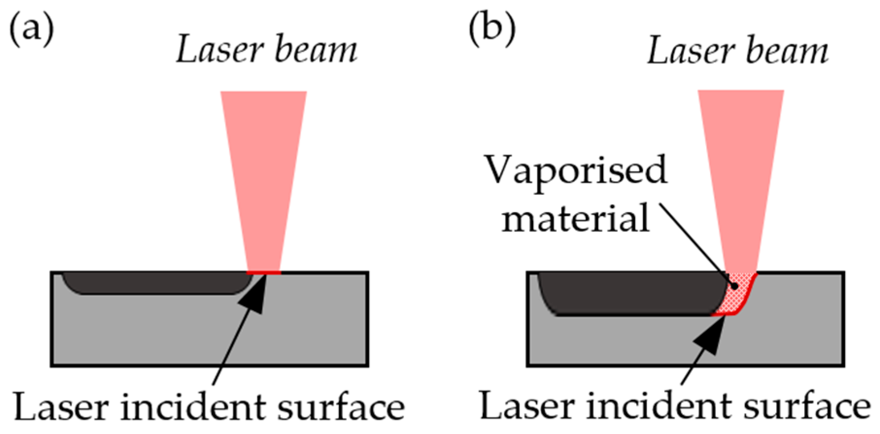
  • Thanks to the consideration of a variable heat source, the model automatically adapts the welding regime from conduction to keyhole if material vaporization is detected. If the temperature in the melt pool reaches the vaporization temperature, the material absorptivity increases to the unit value and vaporized material is eliminated. This approach enables us to obtain accurate results in keyhole or transient welding regimes despite no material movement being considered in the model. Consequently, the model presents a low computational cost and the feasibility of using a cost-effective model for welding applications is demonstrated. This characteristic opens the door to simulating larger and more complex parts.
  • The presented model is able to adapt to the welding regime in each case during the laser welding of dissimilar-thickness Inconel 718 sheets. Therefore, the user does not need to define beforehand the welding regime and the model determines it depending on the thermal field.
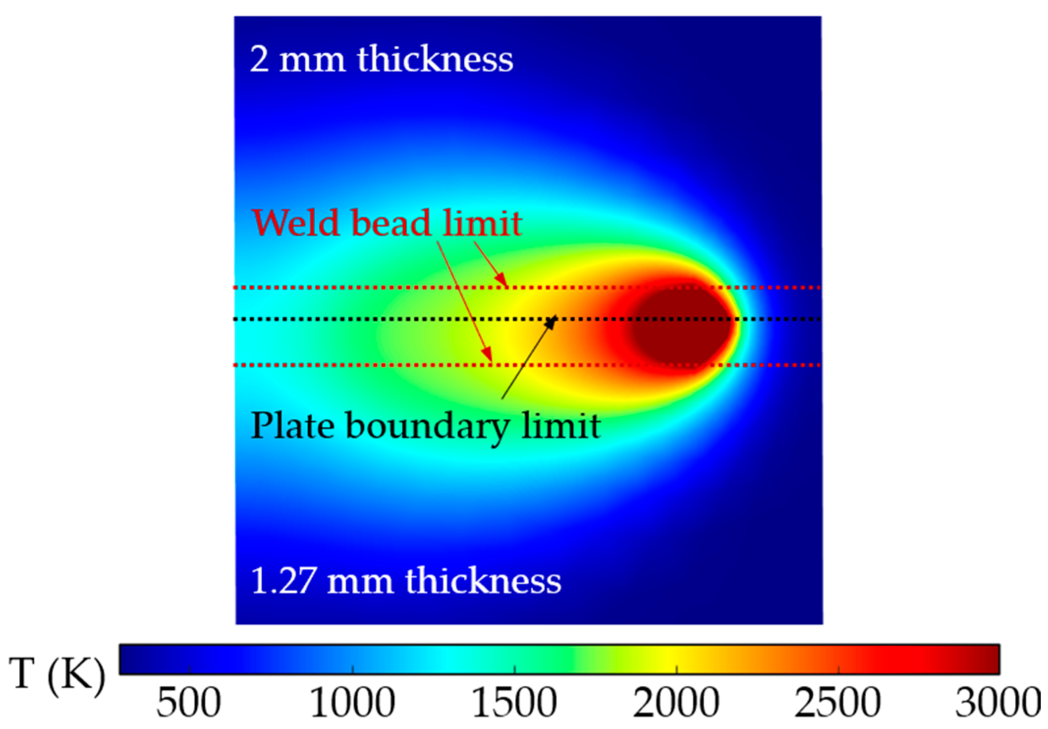
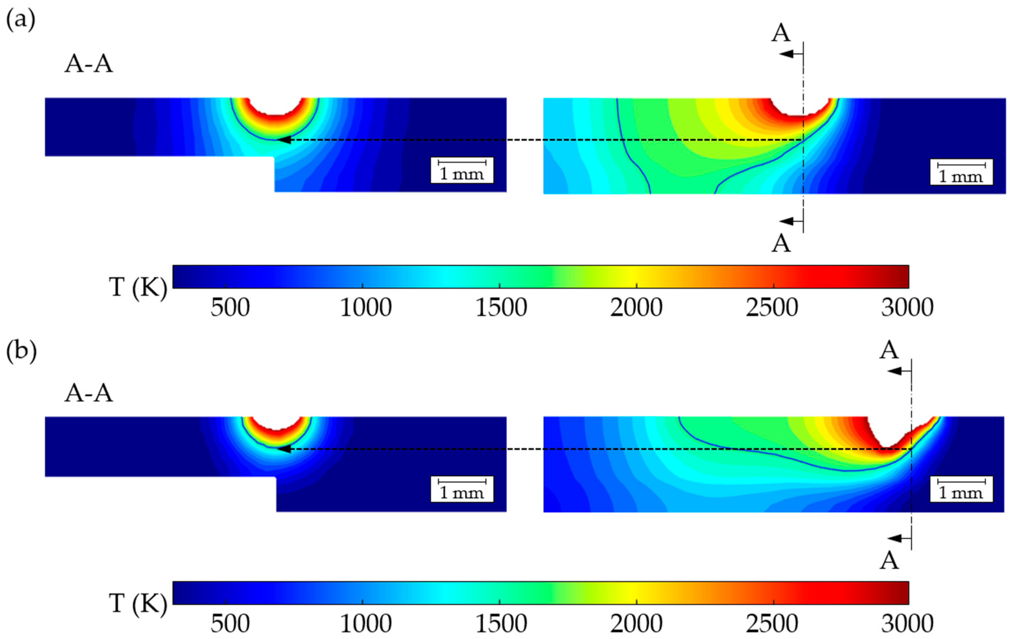
  • The differences in thicknesses of the welded Inconel 718 sheets produces a non-symmetrical thermal field during the welding process. The heat introduced by the laser is directed towards the thinner plate and the developed model is capable of detecting this effect. Consequently, the model can be a useful tool when defining the appropriate welding strategy.
  • The average results between the simulated and measured temperatures provide a reasonable validation of the LBW model. Moreover, the maximum temperature difference obtained among both results is around 20 °C.
  • The dimensions of the melt pool evaluated ex situ by metallography inspection correlate satisfactorily with the results provided by the simulations.
Even if there is still a long way to keep improving LBW models, the model employed in the present case study provides an appropriate prediction of the temperature field and the weld bead itself. Therefore, the next step will be to test the model in different welding configurations or trajectories with complex shapes.

Author Contributions

Conceptualization, O.M. and J.I.A.; methodology, A.L.; validation, O.M.; investigation, O.M. and J.I.A.; resources, H.I.S.; writing—original draft preparation, O.M.; writing—review and editing, O.M., J.I.A., A.L. and H.I.S.; supervision, A.L.; funding acquisition, J.I.A. and A.L. All authors have read and agreed to the published version of the manuscript.

Funding

Grant TED2021-130543B-I00 was funded by MCIN/AEI/10.13039/501100011033 and European Union NextGenerationEU/PRTR. Grant PID2022-141946OB-C21 was funded by MCIN/AEI/10.13039/501100011033/ and by the ERDF A way of making Europe.

Data Availability Statement

The original contributions presented in the study are included in the article; further inquiries can be directed to the corresponding author.

Conflicts of Interest

The authors declare no conflicts of interest. The funders had no role in the design of the study; in the collection, analyses, or interpretation of data; in the writing of the manuscript; or in the decision to publish the results.

References

  1. Sproesser, G.; Chang, Y.J.; Pittner, A.; Finkbeiner, M.; Rethmeier, M. Life Cycle Assessment of welding technologies for thick metal plate welds. J. Clean. Prod. 2015, 108, 46–53. [Google Scholar] [CrossRef]
  2. Balasubramanian, T.S.; Balakrishnan, M.; Balasubramanian, V.; Manickam, M.A.M. Influence of welding processes on microstructure, tensile and impact properties of Ti-6Al-4V alloy joints. Trans. Nonferrous Met. Soc. China 2011, 21, 1253–1262. [Google Scholar] [CrossRef]
  3. Wu, D.; Zhang, P.; Yu, Z.; Gao, Y.; Zhang, H.; Chen, H.; Tian, Y. Progress and perspectives of in-situ optical monitoring in laser beam welding: Sensing, characterization and modeling. J. Manuf. Process. 2022, 75, 767–791. [Google Scholar] [CrossRef]
  4. Blackburn, J. Laser welding of metals for aerospace and other applications. Weld. Join. Aerosp. Mater. 2012, 67–94. [Google Scholar] [CrossRef]
  5. Sonar, T.; Balasubramanian, V.; Malarvizhi, S.; Venkateswaran, T.; Sivakumar, D. An overview on welding of Inconel 718 alloy—Effect of welding processes on microstructural evolution and mechanical properties of joints. Mater. Charact. 2021, 174, 110997. [Google Scholar] [CrossRef]
  6. Muralidharan, B.G.; Shankar, V.; Gill, T. Weldability of Inconel 718—A Review; Indira Gandhi Centre for Atomic Research: Kalfakkam, Tamil Nadu, India, 1996. [Google Scholar]
  7. Farrokhi, F.; Endelt, B.; Kristiansen, M. A numerical model for full and partial penetration hybrid laser welding of thick-section steels. Opt. Laser Technol. 2019, 111, 671–686. [Google Scholar] [CrossRef]
  8. Zhang, L.J.; Zhang, J.X.; Gumenyuk, A.; Rethmeier, M.; Na, S.J. Numerical simulation of full penetration laser welding of thick steel plate with high power high brightness laser. J. Mater. Process. Technol. 2014, 214, 1710–1720. [Google Scholar] [CrossRef]
  9. Shehryar Khan, M.; Shahabad, S.I.; Yavuz, M.; Duley, W.W.; Biro, E.; Zhou, Y. Numerical modelling and experimental validation of the effect of laser beam defocusing on process optimization during fiber laser welding of automotive press-hardened steels. J. Manuf. Process. 2021, 67, 535–544. [Google Scholar] [CrossRef]
  10. Thejasree, P.; Narasimhamu, K.L.; Natarajan, M.; Raju, R. Generative modelling of laser beam welded Inconel 718 thin weldments using ANFIS based hybrid algorithm. Int. J. Interact. Des. Manuf. 2022. [CrossRef]
  11. Lorin, S.; Madrid, J.; Söderberg, R.; Wärmefjord, K. A New Heat Source Model for Keyhole Mode Laser Welding. J. Comput. Inf. Sci. Eng. 2022, 22, 011004. [Google Scholar] [CrossRef]
  12. Zhang, Y.; Dehkordi, M.H.R.; Kholoud, M.J.; Azimy, H.; Li, Z.; Akbari, M. Numerical modeling of the temperature distribution and melt flow in dissimilar fiber laser welding of duplex stainless steel 2205 and low alloy steel. Opt. Laser Technol. 2024, 174, 110575. [Google Scholar] [CrossRef]
  13. Faraji, A.H.; Maletta, C.; Barbieri, G.; Cognini, F.; Bruno, L. Numerical modeling of fluid flow, heat, and mass transfer for similar and dissimilar laser welding of Ti-6Al-4V and Inconel 718. Int. J. Adv. Manuf. Technol. 2021, 114, 899–914. [Google Scholar] [CrossRef]
  14. Duggirala, A.; Kalvettukaran, P.; Acherjee, B.; Mitra, S. Numerical simulation of the temperature field, weld profile, and weld pool dynamics in laser welding of aluminium alloy. Optik 2021, 247, 167990. [Google Scholar] [CrossRef]
  15. Chianese, G.; Hayat, Q.; Jabar, S.; Franciosa, P.; Ceglarek, D.; Patalano, S. A multi-physics CFD study to investigate the impact of laser beam shaping on metal mixing and molten pool dynamics during laser welding of copper to steel for battery terminal-to-casing connections. J. Mater. Process. Technol. 2023, 322, 118202. [Google Scholar] [CrossRef]
  16. Ke, W.; Zeng, Z.; Oliveira, J.P.; Peng, B.; Shen, J.; Tan, C.; Song, X.; Yan, W. Heat transfer and melt flow of keyhole, transition and conduction modes in laser beam oscillating welding. Int. J. Heat Mass Transf. 2023, 203, 123821. [Google Scholar] [CrossRef]
  17. Feng, Y.; Gao, X.; Zhang, Y.; Peng, C.; Gui, X.; Sun, Y.; Xiao, X. Simulation and experiment for dynamics of laser welding keyhole and molten pool at different penetration status. Int. J. Adv. Manuf. Technol. 2021, 112, 2301–2312. [Google Scholar] [CrossRef]
  18. Kamat, S.; Cai, W.; Rinker, T.J.; Bracey, J.; Xi, L.; Tan, W. A novel integrated process-performance model for laser welding of multi-layer battery foils and tabs. J. Mater. Process. Technol. 2023, 320, 118121. [Google Scholar] [CrossRef]
  19. Nayak, L.J.; Roy, G.G. Joining of zircaloy-4 of dissimilar thickness using electron beam welding. Int. J. Adv. Manuf. Technol. 2020, 110, 2323–2340. [Google Scholar] [CrossRef]
  20. Li, Z.; Rostam, K.; Panjehpour, A.; Akbari, M.; Karimipour, A.; Rostami, S. Experimental and numerical study of temperature field and molten pool dimensions in dissimilar thickness laser welding of Ti6Al4V alloy. J. Manuf. Process. 2020, 49, 438–446. [Google Scholar] [CrossRef]
  21. Luo, M.; Shin, Y.C. Vision-based weld pool boundary extraction and width measurement during keyhole fiber laser welding. Opt. Lasers Eng. 2015, 64, 59–70. [Google Scholar] [CrossRef]
  22. Xiao, X.; Liu, X.; Cheng, M.; Song, L. Towards monitoring laser welding process via a coaxial pyrometer. J. Mater. Process. Technol. 2020, 277, 116409. [Google Scholar] [CrossRef]
  23. Mills, K.C. Recommended Values of Thermophysical Properties for Selected Commercial Alloys; Woodhead Publishing: Sawston, UK, 2002. [Google Scholar]
  24. ISO/TS 18166:2016; Numerical Welding Simulation—Execution and Documentation. ISO: Geneva, Switzerland, 2016.
  25. Katayama, S. Handbook of Laser Welding Technologies; Woodhead Publishing: Sawston, UK, 2013. [Google Scholar]
Figure 1. Setup for experimental tests.
Metals 14 00829 g001
Figure 2. Outline representation of three types of boundary conditions.
Metals 14 00829 g002
Figure 3. Laser incident surface: (a) conduction and (b) keyhole welding modes.
Metals 14 00829 g003
Figure 4. Three-dimensional geometry of the simulation: (a) indicates the clamping sides and the weld joint position, and (b) indicates the employed mesh.
Metals 14 00829 g004
Figure 5. Machine-integrated monitoring setup for experimental tests.
Metals 14 00829 g005
Figure 6. Experimental temperature measurements during welding tests 1 and 2.
Metals 14 00829 g006
Figure 7. Thermal field evolution during the test 2 simulation.
Metals 14 00829 g007
Figure 8. Test 1 simulation results on the top surface.
Metals 14 00829 g008
Figure 9. Transversal and longitudinal cross-sections; (a) test 1 and (b) test 2.
Metals 14 00829 g009
Figure 10. The weld bead dimension validation of test 2: (a) cross-section 1 situated at a 20 mm distance from the weld beginning, (b) cross-section 2 situated at a 50 mm distance from the weld beginning.
Metals 14 00829 g010
Table 1. Chemical composition of as-received Inconel 718 (wt. %).
NiCoFeCrNb+TaMo
Bal. (52)<1.00019.00018.0005.0003.000
MnSiTiAlCB
<0.350<0.3500.9000.5000.0500.004
Table 2. Thermophysical properties of Inconel 718. Reprinted with permission from ref. [23] 2002, Woodhead.
Temperature [K]Density [kg∙m−3]Specific Heat [J∙kg−1∙K−1]Thermal Conductivity [W∙m−1∙K−1]
29881904358.9
373816045510.8
473811847912.9
573807949715.2
673804051517.4
773800152718.7
873796255820.8
973792556821.9
1073788458523.9
1173784560325.8
1273780662026.7
1373776764028.3
1443772765029.3
1609740072029.6
Table 3. Case study parameters for the experimental tests.
TestPower [W]Welding Speed [mm·min−1]Ølaser [mm]
18005001
280010001
Table 4. Temperature validation of the case study.
TestTPyrometer [K]TModel [K]E [%]
11637.531650.190.77
21580.771600.801.27
Table 5. Numerical values of the weld bead dimension validation.
TestDExp [mm]DModel [mm]ED [%]WExp [mm]WModel [mm]EW [%]
12.001.990.442.532.2412.91
21.070.989.181.621.4710.61
Disclaimer/Publisher’s Note: The statements, opinions and data contained in all publications are solely those of the individual author(s) and contributor(s) and not of MDPI and/or the editor(s). MDPI and/or the editor(s) disclaim responsibility for any injury to people or property resulting from any ideas, methods, instructions or products referred to in the content.

