Article

Variation in Flow Characteristics of Molten Baths at Different Blowing Stages in the Converter

1
School of Metallurgical Engineering, Xi’an University of Architecture and Technology, Xi’an 710055, China
2
Shaanxi Longmen Iron and Steel Co., Ltd., Hancheng 715405, China
*
Authors to whom correspondence should be addressed.
Metals 2024, 14(8), 860; https://doi.org/10.3390/met14080860
Submission received: 25 June 2024 / Revised: 18 July 2024 / Accepted: 23 July 2024 / Published: 26 July 2024
(This article belongs to the Section Extractive Metallurgy)

Abstract

:
The metallurgical tasks at different stages of converter blowing are different. The process operation and physical properties of molten baths are also different. It is very important to determine the flow characteristics of molten baths at different blowing stages for optimizing process operation. In this paper, a three-dimensional, full-scale model of a 120 t top–bottom combined blowing converter is established. Based on the parameters of oxygen lance position, bath temperature, bottom blowing intensity, and bath physical properties at different blowing stages, the changes in bath flow field, turbulent kinetic energy, impact depth, impact area, and wall shear force with blowing process are studied. The results show that at the initial stage of blowing, the lance position is high, the impact depth of the molten bath is 0.23 m, the impact area is 5.06 m2, the dead zone area of the longitudinal section is 0.40 m2, and the high-speed zone area is 2.73 m2. As the blowing time increases, the lance position decreases, the impact depth of the molten bath increases, the impact area decreases, and the internal velocity of the molten bath increases. In the later stage of tuyere blowing, the lance level decreases to its lowest, the impact depth increases to 0.42 m, the impact area decreases to 2.83 m2, the dead zone area of longitudinal section decreases to 0.18 m2, and the high-speed area increases to 3.34 m2. The area with the highest wall shear stress is situated within the gas–slag–metal three-phase region, where the lining experiences the most significant erosion. The fluctuation in the slag–metal interface is small, and the wall shear force is 2.80 Pa at the initial stage of blowing. From the early to late stages of blowing, the lance position decreases, the fluctuation range of the slag–metal interface increases, and the erosion of the furnace lining increases. In the later stage of blowing, the maximum wall shear force is 3.81 Pa.

1. Introduction

Supersonic oxygen is injected into a molten bath in the converter steelmaking process for completing metallurgical tasks such as dephosphorization, decarburization, and heating [1,2]. The oxygen blowing process can be divided into the early stage, the middle stage, the middle-late stage, and the late stage, according to different metallurgical tasks and molten bath characteristics. The alteration in the molten bath flow characteristics during various stages significantly impacts the achievement of rapid slagging, high-efficiency dephosphorization and decarbonization, as well as the stable heating of the converter. Therefore, it is crucial to investigate the flow characteristics of the molten bath during different blowing stages in the converter steelmaking process [3,4].
The effects of Mach number, oxygen temperature [5], nozzle wear [6,7], oxygen lance structure [8], and rotation angle [9] on supersonic oxygen jets have been investigated using numerical simulation [10] and theoretical calculations [11]. The factors influencing supersonic oxygen jets were shown and the corresponding improvement measures were suggested. In order to further investigate the behavioral characteristics of oxygen jets and converter molten baths [12], the three-phase flow characteristics under different conditions have been investigated by varying the oxygen supply flow rate [13], the oxygen lance position [14,15], the atmosphere temperature, the working pressure, and so on, to investigate the change in the flow field inside converter molten baths. Through the water simulation method [16,17,18], the mixing time, impact depth, and impact area of molten baths [19] have been studied by varying parameters such as the top-blowing flow rate and lance position [20], which clearly and intuitively explain the behavioral characteristics of the relationship between the oxygen jet and molten bath. Converter steelmaking involves multiple tasks and processes resulting in physical and chemical changes. Based on the different process parameters of different blowing stages, some scholars have studied the composition and physical properties of converter slag at different blowing stages through theoretical calculations and other methods [21,22]. Numerous studies have been conducted by researchers on the characteristics of converter oxygen lance jets and molten bath stirring, and effective measures have been taken to improve the flow of the converter molten bath [23]. However, the oxygen jet and molten bath flow characteristics at different blowing stages in basic oxygen furnace (BOF) converters have not been studied.
In this study, a three-dimensional full-size model of a 120 t top–bottom combined blowing converter was established. Based on process parameters such as oxygen supply lance position, bath temperature, bottom blowing intensity, and bath physical properties at different blowing stages, the bath flow, turbulent kinetic energy distribution, impact characteristics, and wall shear force changes at different blowing stages were explored. This research can offer a significant reference for optimizing the converter process system.

2. Mathematical Model

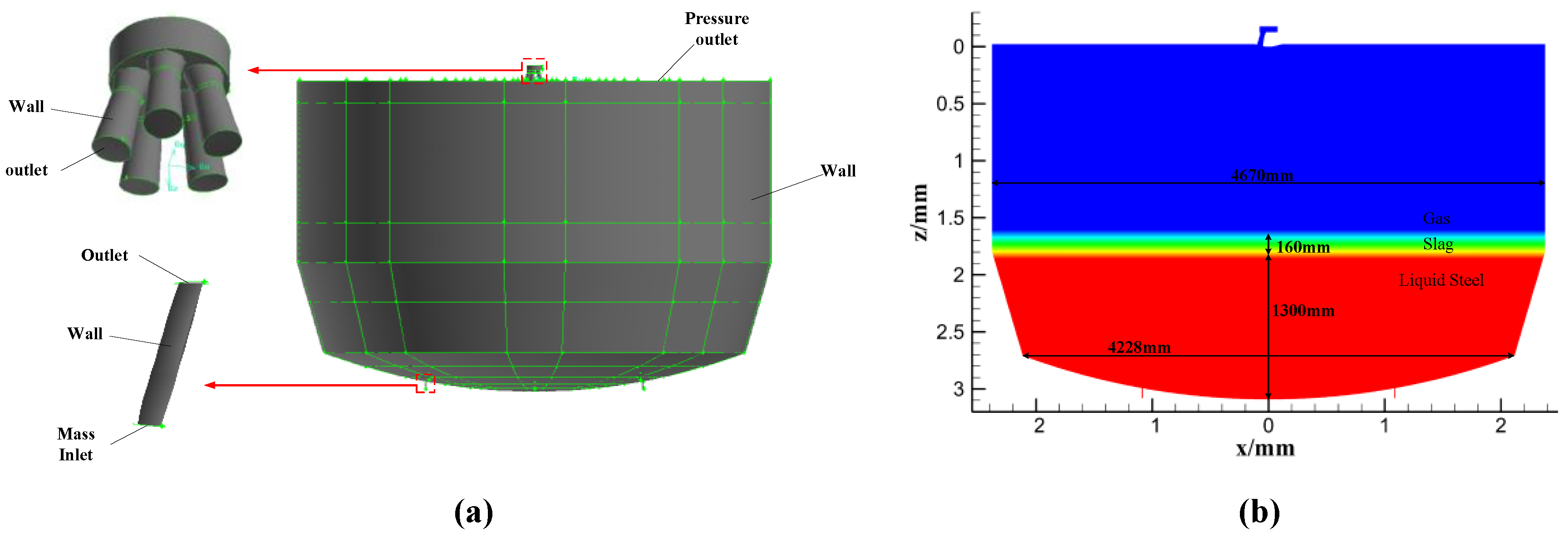
2.1. Modelling and Meshing

The full-scale geometric model of a 120-ton top–bottom blowing converter and oxygen lance was established. Hexahedral meshing was conducted using Gambit software 2.4.6, resulting in approximately 1,436,322 mesh elements, as depicted in Figure 1. To enhance accuracy, the meshes near the bottom blowing element and oxygen lance were refined. Table 1 shows the model geometry.

2.2. Research Program

In this study, the converter blowing process was divided into four stages.
The early stage involved oxygen blowing from 0 to 4 min. The temperature of the molten bath was about 1300 °C. The main task here was the oxidation of silicon and manganese as well as quick slagging to achieve low-temperature and efficient dephosphorization.
The middle stage involved blowing oxygen for 5–8 min. The temperature of the molten bath was increased to more than 1400 °C, the oxygen lance position was lowered to strengthen the stirring of the molten bath, the carbon and oxygen reaction speed was accelerated, and the molten bath was rapidly decarburized and heated up.
In the middle-late stage, oxygen was blown at 9–12 min. After the molten bath temperature increased to 1500 °C, due to the blowing in the middle and late stage, the decarbonization rate reduced. Due to the middle of the carbon and oxygen reaction of the intense slag resulting in a reduction in the content of FeO, there were a return to dryness, a rapid adjustment of the lance position to inhibit the return to dryness, and then further reductions in the lance position to achieve the required dephosphorization and decarbonization as well as a smooth temperature rise.
In the late stage, after blowing oxygen for 12 min, which was the end of oxygen blowing, the molten bath temperature rose to more than 1600 °C. This brought the molten bath close to the converter before the steel lowering of the lance position for more than 30 s. This strengthened the stirring of the molten bath, promoted the reaction to reduce the slag loss of iron, and further homogenized the composition and temperature of the molten bath.
In order to study the flow characteristics of the oxygen lance jet and molten bath at different blowing stages, a research plan was developed based on the actual blowing process system of the 120 t converter, and the simulated parameters are shown in Table 2.
The physical parameters of molten steel at different blowing stages were calculated using JMatPro 4.0. The composition of the molten steel at different stages is shown in Table 3.

2.3. Governing Equation

(1) Turbulence Models (k-ε Model) [24]:
The equations governing the turbulent kinetic energy k and turbulent dissipation rate ε in the standard k-ε turbulence model are expressed as follows:
The turbulent kinetic energy (k) equation is
ρ k t + ρ k v i x i = x j μ + μ t σ k k x j + G k + G b ρ ε Y m + S k
where ρ is the fluid density (kg/m3); k is the turbulent kinetic energy (m2/s2); v i represents the flow velocity component in the i direction (m/s); μ denotes the molecular viscosity (Pa·s); μ t denotes the turbulent viscosity coefficient (Pa·s); σ k is the Prandtl number for k; G k represents the production of turbulent kinetic energy due to the mean velocity gradient (m2/s2); G b represents the production of turbulent kinetic energy due to buoyancy (m2/s2); ε is the turbulent dissipation rate (m2/s3); Y m represents the influence of compressible turbulent fluctuations and expansion on the dissipation rate; S k denotes the user-defined source term for turbulent kinetic energy.
The turbulent dissipation rate (ε) equation is
ρ ε t + ρ ε v i x i = x j μ + μ t σ ε ε x j + C 1 ε ε k G k + C 3 ε G b C 2 ε ρ ε 2 k + S ε
where ε is the turbulent dissipation rate (m2/s3); C 1 ε , C 2 ε , and C 3 ε are constants with C 1 ε ; C 2 ε = 1.92; and C 3 ε = 0.
(2) Volume of Fluid (VOF) Model [25]
For the volume of fluid (VOF) model, the conservation equations governing phase fractions and fluid momentum are described as follows:
The continuity equation is
α q ρ q t + α q ρ q v q = 0
The momentum equation is
ρ v t + ρ v v = p + τ + ρ g + f σ
where   α q   is the volume fraction of the qth-phase;   ρ q   is the density of the qth-phase fluid (kg/m3); v q   is the velocity vector of the qth-phase fluid (m/s); ρ   is the fluid density (kg/m3); v is the fluid velocity vector (m/s); p   is the gas-phase pressure (Pa); τ   is the stress tensor; g is the gravitational acceleration (m/s2); f σ   denotes the interfacial momentum exchange.

2.4. Assumptions and Boundary Conditions

The assumptions made during the simulation process were as follows:
A.
Oxygen and argon were assumed to be ideal gases, following the ideal gas law.
B.
The chemical reactions between gases and the molten bath were not considered.
C.
The flow of oxygen inside the lance nozzle was assumed to be adiabatic and frictionless.
The boundary conditions are illustrated in Figure 2. Fluent software was employed for transient calculations. The inlet of the oxygen lance and the bottom blowing element were configured as mass inflow ports, while the upper surface of the computational domain served as the pressure outlet, set at 104,000 Pa. All other surfaces were designated as wall conditions. Density, momentum, turbulent kinetic energy, turbulent dissipation rate, and energy were discretized using second-order upwind schemes. The volume fraction was computed using the geo-reconstruct method, and the pressure was calculated using the body weighting method. The convergence criteria of 10−6 for the energy equation and 10−3 for other equations, along with a time step of 10−5, ensured the high accuracy and stability of the results while managing computational efficiency.

3. Analysis and Discussion

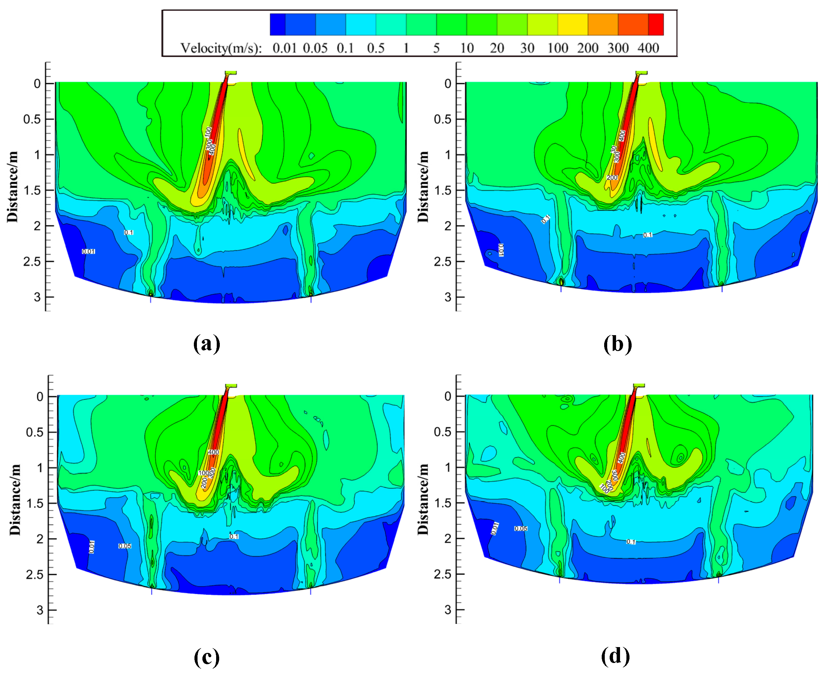
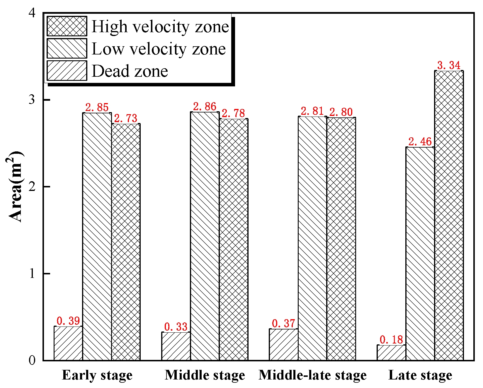
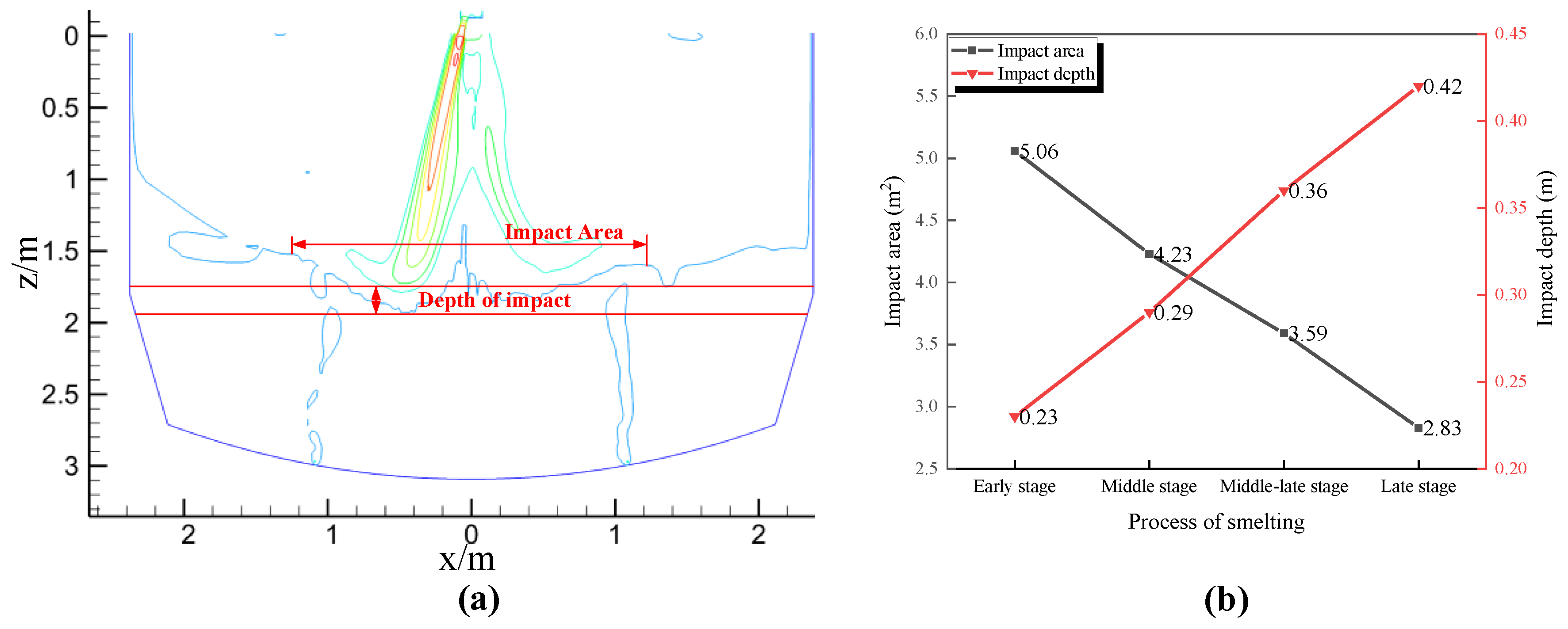
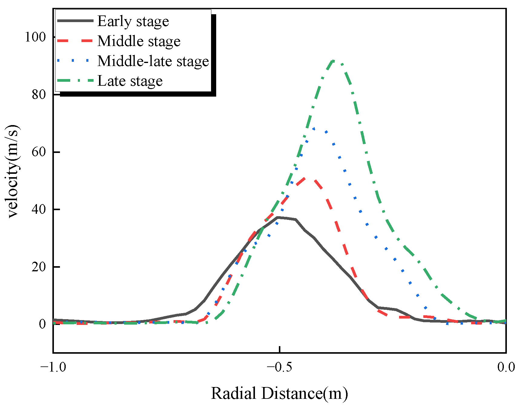
3.1. Flow Behavior of Molten Bath

During the converter steelmaking process, the flow velocity of the molten bath significantly influences the interfacial chemical reactions, mixing time, and metallurgical outcomes. As illustrated in Figure 3, the longitudinal cross-sectional velocity distribution of the molten bath exhibits distinct patterns during various blowing stages. High-velocity regions are primarily concentrated in the impact craters at the top and the air-blowing zones at the bottom. Conversely, lower velocities characterize the dead zones at the center bottom and the furnace wall bottom. The remaining areas fall into the category of low-velocity regions. The blowing stage is from the early stage to the late stage, and the lance position decreases. Oxygen jet impact on the molten bath is enhanced, and the area of the upper layer of the molten bath with a velocity greater than 0.1 m/s increases. At the same time, as the lance position decreases, the oxygen jet’s convolution to the low-velocity furnace gas decreases. The velocity of the jet reaching the liquid steel surface increases, which increases the stirring ability of the oxygen jet on the molten bath.
In order to further analyze the flow field distribution of the molten bath, the areas of the regions with different velocities re shown in Figure 4. We defined V < 0.01 m∙s−1 as the dead zone, 0.01 m∙s−1 ≤ V ≤ 0.1 m∙s−1 a the low-velocity zone, and V > 0.1 m∙s−1 as the high-velocity zone of the molten bath. From the early to late stages of blowing, the area of the high-velocity zone increases, and the dead zone in the molten bath decreases, then increases and decreases again. At the early stage, the dead zone area of the longitudinal section of the molten bath is 0.39 m2, and the area of the high-velocity zone is 2.73 m2. In the middle stage, the area of the dead zone decreases to 0.33 m2, which is lower by 15.38%, and the area of the high-velocity zone increases to 2.78 m2, which is larger by 1.83%. In the middle-late stage, the dead zone area of the molten bath increases to 0.37 m2, which is an increase of 12.12%, and the area of the high-velocity zone increases to 2.80 m2, an increase of 0.72%. At the late stage, the dead zone area reduces to 0.18 m2, which is a decrease of 51.35%; the area of the high-velocity zone increases to 3.34 m2, which is an increase of 19.29%.
We analyzed the reason for these findings. From the early stage to the middle stage of blowing, the lance position decreases, the impact of the oxygen jet on the molten bath increases, the stirring intensity increases, and the fluidity of the molten bath increases. Therefore, the dead zone area decreases. From the middle to the middle-late stage, the lance position is further reduced. However, as the liquid steel temperature increases, the viscosity of the molten bath increases. At the same time, the bottom blowing intensity is smaller, the molten bath fluidity decreases, and the dead zone area increases. In the middle-late to late stage, the lance position decreases and the bottom blowing intensity increases. The stirring capacity of the molten bath increases, and the dead zone area of the molten bath decreases.

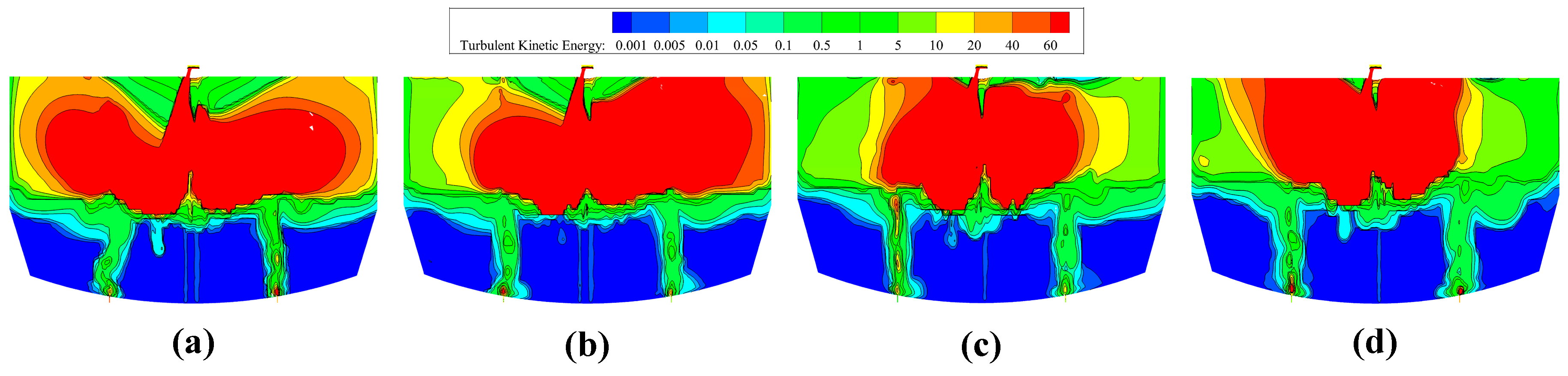
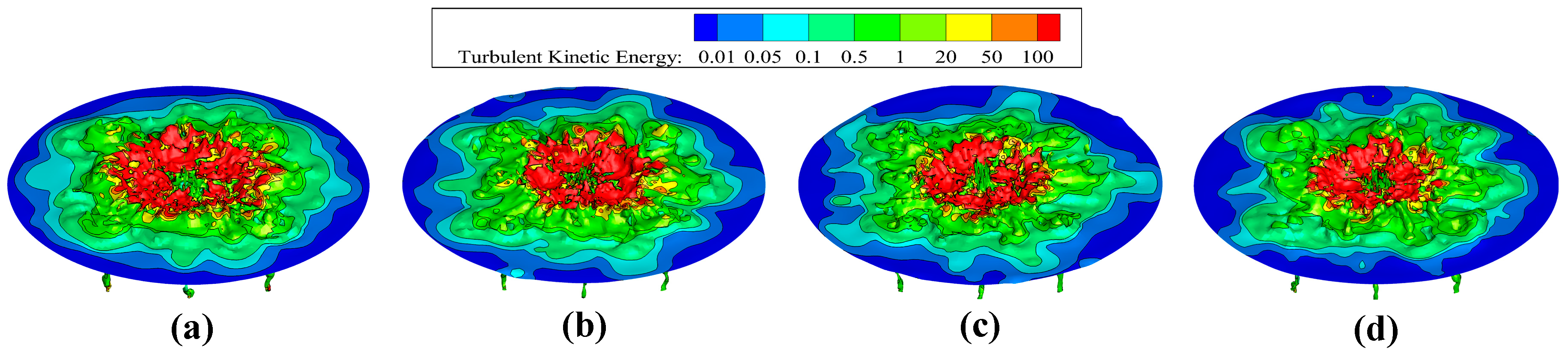
3.2. Turbulent Energy Distribution

Figure 5 depicts the distribution of the turbulent kinetic energy along the longitudinal section of the molten bath at different stages of purging. In the longitudinal section, the regions of elevated turbulent kinetic energy are primarily concentrated around the impact pit, the upper layer of molten steel, and the vicinity of the bottom blowing stream. As refining time increases and the lance position lowers, the area with turbulent kinetic energy exceeding 0.01 m2/s2 in the bath increases from 1.95 m2 in the early stages of ironmaking to 2.14 m2. Conversely, the area of turbulent kinetic energy exceeding 60 m2/s2 above the bath decreases from 4.23 m2 to 3.08 m2. This reduction is primarily due to the decreased influence of the oxygen jet on the convective air above the bath as the lance position decreases, thereby reducing the generation of turbulent kinetic energy.
Figure 6 illustrates the distribution of turbulent kinetic energy on the surface of the molten steel at different blowing stages. As blowing time increases, the area on the steel surface with a turbulent kinetic energy exceeding 100 m2/s2 contracts toward the center. Initially at 2.81 m2, this area reduces to 1.91 m2 during the later stages of blowing. This reduction occurs because the oxygen lance descends from early to later stages. Consequently, the range of the oxygen jet impacting the steel liquid surface narrows toward the center, leading to a decrease in the affected area.

3.3. Variation in Gas–Slag–Metal Multiphase Flow Characteristics

Impact depth and impact area are important indices for evaluating the characteristics of a jet’s impact on a molten bath. Figure 7 shows the impact depth and impact area of the oxygen lance jet at different blowing stages. Impact depth increases with blowing time, and impact area decreases with blowing time. As the blowing time increases, the oxygen lance position decreases, the kinetic energy of the jet to reach the surface of the liquid steel increases, the impact force on the molten bath increases, and the depth of the molten bath impact increases. As the lance position decreases, the radial spacing between the jet strands decreases, the area of the jet acting on the molten bath decreases, and the impact area of the molten bath decreases. From the early stage to late stage of blowing, the impact depth increases from 0.23 m to 0.42 m, which is an 82.6% increase. The impact area reduces from 5.06 m2 to 2.83 m2, a reduction of 44.1%.
In order to further analyze the interface characteristics of gas–slag–metal three-phase interactions, the gas–slag–metal interface velocity distribution at different blowing stages is as shown in Figure 8. As the radial distance of the gas–slag–metal three-phase interface increases from the center outward, the interfacial velocity increases and then decreases. From the early stage to the late stage of blowing, the oxygen lance position decreases, the depth of jet impact increases, and the impact area decreases. The oxygen jet impingement shrinks toward the center of the molten bath, so the maximum interface velocity increases, and the position of the maximum velocity moves toward the center of the molten bath. The maximum values of the velocity of the four blowing stages are 37.2 m/s, 50.9 m/s, 68.6 m/s, and 91.7 m/s, respectively.

3.4. Wall Shear

The wall shear stress is a crucial factor in the erosion of converter linings. Figure 9 illustrates the variation in wall shear stress during different blowing stages. The area with large shear stress is located in the gas–slag–metal three-phase interaction area, where the erosion are the largest. As the lance position decreases, the wall shear increases gradually. At the beginning of blowing, the force of the oxygen jet on the gas–slag–metal three-phase region is small, the slag–metal interface fluctuation amplitude is small, and the wall shear stress is small, with a maximum value of 2.80 Pa. At the late stage of blowing, the kinetic energy of the oxygen jet arriving at the slag–metal interface increases, the fluctuation amplitude of the slag–metal interface is larger, the erosion of the converter lining increases, and the wall shear is the largest, with a maximum value of 3.81 Pa.

4. Conclusions

(1) From the early stage to the late stage of blowing, the lance position decreases, the radial distance at the end of the oxygen jet decreases, the interaction between the top blowing stream and the bottom blowing stream weakens, and the fluidity of the molten bath increases. The dead zone of the molten bath on the longitudinal section measures 0.39 m2, 0.33 m2, 0.37 m2, and 0.18 m2 from the first to the last stage, respectively, while the high-velocity zone on the longitudinal section covers areas of 2.73 m2, 2.78 m2, 2.80 m2, and 3.34 m2, respectively.
(2) From the early to late stages of blowing, the oxygen lance position decreases, the impact depth increases, the internal velocity of the molten bath increases, and the impact depth increases from 0.23 m to 0.42 m. As the oxygen lance position decreases, the radial spacing between the jet streams decreases, and the impact area decreases from 5.06 m2 to 2.83 m2.
(3) The region with the largest wall shear stress is located in the gas–slag–metal three-phase region. In the early stage of blowing, the kinetic energy of oxygen jet reaching the slag–metal interface is small, the fluctuation range of the slag–metal interface is small, and the maximum wall shear force is 2.80 Pa. From the early to late stages of blowing, the fluctuation range of the slag–metal interface increases. In the later stage of smelting, the oxygen jet has a great impact on the slag–metal interface, and the maximum wall shear force is 3.81 Pa.

Author Contributions

Conceptualization, S.C., F.H., and Y.H.; methodology, S.C., F.H., and Y.H.; software, S.C., F.H., and Y.H.; validation, S.C., F.H., and Y.H.; formal analysis, M.L., H.G., and Z.Z.; investigation, M.L., H.G., and Z.Z.; formal analysis, M.L., H.G., and Z.Z.; investigation, M.L., H.G., and Z.Z.; resources, M.L., H.G., and Z.Z.; data curation, M.L., H.G., and Z.Z. original draft preparation, Y.H.; writing-review and editing, M.L.; supervision, M.L., and Z.Z.; project administration, M.L., and Z.Z.; funding acquisition, M.L. All authors have read and agreed to the published version of the manuscript.

Funding

This research was funded by [National Natural Science Foundation of China] [Department of Education Service Local Special Plan Project of Shaanxi Province] and grant number [52374346] [22JC044]. The APC was funded by [National Natural Science Foundation of China] and [Department of Education Service Local Special Plan Project of Shaanxi Province].

Data Availability Statement

The data that support the findings of this study are available on request from the corresponding author, upon reasonable request.

Acknowledgments

Corresponding author on behalf of all authors wish to thank the National Natural Science Foundation of China for grant No. 52374346, the Department of Education Service Local Special Plan Project of Shaanxi Province (22JC044), and Innovation Capacity Support Program Funded Projects (2023-CX-TD-53) for the financial support to carry out this research.

Conflicts of Interest

Author Hongmin Guo was employed by the company Shaanxi Longmen Iron and Steel Co., Ltd. The remaining authors declare that the research was conducted in the absence of any commercial or financial relationships that could be construed as a potential conflict of interest. On behalf of all authors, the corresponding author states that there is no conflicts of interest.

References

  1. Li, J.-G.; Zeng, Y.-N.; Wang, J.-Q.; Han, Z.-J. Simulation of Flow Field of Oxygen Lance Gas Jet Utilized for 50 t Converter. J. Iron Steel Res. Int. 2011, 18, 11–18. [Google Scholar] [CrossRef]
  2. Li, M.-M.; Li, Q.; Kuang, S.-B.; Zhou, Z.-S. Coalescence Characteristics of Supersonic Jets from Multi-Nozzle Oxygen Lance in Steelmaking BOF. Steel Res. Int. 2015, 86, 1517–1529. [Google Scholar] [CrossRef]
  3. Sun, J.-K.; Zhang, J.-S.; Lin, W.-H.; Cao, L.-L.; Feng, X.-M.; Liu, Q. Effect of impact cavity shape induced by supersonic oxygen jet on the dynamic characteristics of molten bath in converter. Steel Res. Int. 2021, 92, 2100179. [Google Scholar] [CrossRef]
  4. Wang, X.; Liu, G.-Q.; Liu, K. Behaviors of supersonic double-parameter jets and their impingement onto molten bath in BOF steelmaking. AIP Adv. 2023, 10, 105307. [Google Scholar] [CrossRef]
  5. Li, Y.-X.; Jia, H.-B.; Liu, J.-Q.; Liu, K. Mathematical model of supersonic jet centerline velocity for multi-nozzle oxygen lance. Metall. Res. Technol. 2022, 119, 506. [Google Scholar] [CrossRef]
  6. Jia, H.-B.; Li, Y.-X.; Liu, K.; Feng, L.-H. Study on jet characteristics of a dual-structure converter oxygen lance based on hydrodynamics. AIP Adv. 2022, 12, 075026. [Google Scholar] [CrossRef]
  7. Zhao, F.; Liu, F.-H.; Sun, D.-B.; Zhu, R.; Dong, K. Behaviors of Supersonic Oxygen Multi-jets with Various Preheating Temperatures. Metall. Mater. Trans. B. 2021, 53, 2626–2641. [Google Scholar] [CrossRef]
  8. Zhang, H.; Liu, K.; Zhao, H.-X.; Tian, Y.; Liang, J.-Y.; Yuan, Z.-F. Numerical Simulation of Innovative Slag Splashing Process in a Converter Using a Nozzle-Twisted Oxygen Lance. J. Sustain. Metall. 2024, 10, 864–879. [Google Scholar] [CrossRef]
  9. Feng, C.; Zhu, R.; Han, B.-H.; Yao, L.-J.; Wu, W.-H.; Wei, G.-S.; Dong, J.-F.; Jiang, J.-J.; Hu, S.-Y. Effect of Nozzle Exit Wear on the Fluid Flow Characteristics of Supersonic Oxygen Lance. Metall. Mater. Trans. B. 2019, 51, 187–199. [Google Scholar] [CrossRef]
  10. Feng, C.; Zhu, R.; Dong, K.; Wei, G.-S.; Han, B.-C.; Li, W.-F.; Wu, W.-H. Effects of Nozzle Layout and Parameters on the Jet Characteristics of a CO2 + O2 Mixed Oxygen Lance. Metall. Mater. Trans. B. 2021, 52, 425–439. [Google Scholar] [CrossRef]
  11. Wang, X.; Han, P.; Liu, K. Effect of multi-angle parameter on fluid flow characteristics of swirl-type oxygen lance. Metall. Res. Technol. 2022, 119, 314. [Google Scholar] [CrossRef]
  12. Jia, H.-B.; Han, P.; Liu, K.; Li, Y.-X.; Ba, K.-J.; Feng, L.-H. Jet characteristics of a double-structure oxygen lance and its interaction with the molten pool in BOF steelmaking. AIP Adv. 2021, 11, 285330. [Google Scholar] [CrossRef]
  13. Chu, K.-Y.; Chen, H.-H.; Lai, P.-H.; Wu, H.-C.; Liu, Y.-C.; Lin, C.-C.; Lu, M.-J. The Effects of Bottom Blowing Gas Flow Rate Distribution During the Steelmaking Converter Process on Mixing Efficiency. Metall. Mater. Trans. B. 2016, 48, 948–962. [Google Scholar] [CrossRef]
  14. Li, Q.; Li, M.-M.; Kuang, S.-B.; Zou, Z.-S. Numerical Simulation of the Interaction Between Supersonic Oxygen Jets and Molten Slag–Metal Bath in Steelmaking BOF Process. Metall. Mater. Trans. B. 2015, 46, 1494–1509. [Google Scholar] [CrossRef]
  15. Jiang, B.-C.; Guo, X.-Y.; Wang, Q.-M. Analysis of Melt Flow Characteristics in Large Bottom-Blowing Furnace Strengthened by Oxygen Lance Jet at Different Positions. J. Sustain. Metall. 2023, 9, 1704–1715. [Google Scholar] [CrossRef]
  16. Li, Z.-H.; Yang, X.-J.; Zhou, Q.-L.; Zhang, Q.; Sun, J.-Y.; Zhong, L.-C. Influence of non-uniform gas supply to bottom blowing of a re-blowing converter on molten pool mixing and blending. J. Iron Steel Res. 2020, 32, 788–799. [Google Scholar]
  17. Yao, L.-J.; Zhu, R.; Dong, k.; Wei, G.-S.; Feng, C.; Tang, Y.-X. Influence of the non-uniform bottom blowing gas supply mode on the dynamic conditions of molten pool during the converter steelmaking process. Ironmak. Steelmak. 2020, 48, 1. [Google Scholar] [CrossRef]
  18. Cai, X.-Y.; Duan, H.-J.; Li, D.-H.; Xu, A.-J.; Zhang, L.-F. S Water modeling on fluid flow and mixing phenomena in a BOF steelmaking converter. J. Iron Steel Res. Int. 2023, 31, 595–607. [Google Scholar] [CrossRef]
  19. Li, Z.-Z.; Zhu, R.; Liu, R.-Z.; Lv, M.; Wang, H.-Z. Effect of oxygen lance position on the flow velocity of molten steel in BOF. Chin. J. Eng. 2014, 36, 15–20. [Google Scholar]
  20. Baricová, D.; Pribulová, A.; Futáš, P.; Buľko, B.; Demeter, P. Change of the Chemical and Mineralogical Composition of the Slag during Oxygen Blowing in the Oxygen Converter Process. Metals 2018, 8, 844. [Google Scholar] [CrossRef]
  21. Wang, M.-L.; Yang, W.-Y. Dephosphorization in the early stage of converter steelmaking. Ironmak. Steelmak. 2020, 47, 1127–21134. [Google Scholar] [CrossRef]
  22. Yu, L.-G.; Feng, L.-H.; Nie, D.; Liu, Y. Simulation study on multiphase behavior of gas-metal-slag in the 260t converter. Metall. Res. Technol. 2022, 119, 613. [Google Scholar] [CrossRef]
  23. Lv, M.; Li, H.; Xing, X.-D.; Lin, T.-C.; Hu, S.-Y.; Xie, K. Variation in Multiphase Flow Characteristics by Nozzle-Twisted Lance Blowing in Converter Steelmaking Process. Steel Res. Int. 2022, 93, 2100409. [Google Scholar] [CrossRef]
  24. Liu, C.; Zheng, S.-G.; Zhu, M.-Y. Numerical Study of the Kinetics of Dephosphorization with Single-Flow Post-combustion Oxygen Lance in Converter Steelmaking Process. Metall. Mater. Trans. B. 2024, 55, 999–1013. [Google Scholar] [CrossRef]
  25. Zhang, J.-S.; Lou, W.-T.; Zhu, M.-Y. Numerical Simulation of Particle Transport Phenomenon in Steelmaking Converter with Bottom Powder Injection Based on Eulerian-Multifluid VOF-Granular Flow Model. Metall. Mater. Trans. B. 2024, 54, 1449–1467. [Google Scholar] [CrossRef]
Figure 1. Computational domain meshing: (a) converter model meshing, (b) bottom element arrangement.
Metals 14 00860 g001
Figure 2. Calculation domain schematic and boundary condition settings. (a) Boundary condition; (b) calculation domain schematic.
Metals 14 00860 g002
Figure 3. Longitudinal velocity distribution of molten bath at different blowing stages. (a) Early stage; (b) middle stage; (c) middle-late stage; (d) late stage.
Metals 14 00860 g003
Figure 4. Regional distribution of molten bath velocity at different blowing stages.
Metals 14 00860 g004
Figure 5. Distribution of turbulent energy in the longitudinal section of the molten bath at different blowing stages. (a) Early stage; (b) middle stage; (c) middle-late stage; (d) late stage.
Metals 14 00860 g005
Figure 6. Distribution of turbulent kinetic energy on steel surface at different blowing stages. (a) Early stage; (b) middle stage; (c) middle-late stage; (d) late stage.
Metals 14 00860 g006
Figure 7. Impact depth and impact area of molten bath at different blowing stages. (a) Impact effect; (b) impact depth and impact area.
Metals 14 00860 g007
Figure 8. Velocity distribution of gas–slag–metal interface at different blowing stages.
Metals 14 00860 g008
Figure 9. Wall shear at different blowing stages.
Metals 14 00860 g009
Table 1. Model geometry.
Characteristic/UnitValue
ConverterNominal capacity/t120
Caliber/mm4670
Pool depth/mm1300
Oxygen lanceThroat diameter/mm39.7
Outlet diameter/mm51.57
Outlet length/mm84.93
Oxygen supply flow rate/(m3·h−1)29,000
Number of holes5
Mach number2.0
Nozzle angle/(°)13
Table 2. Simulated parameters.
Early StageMiddle StageMiddle-Late StageLage Stage
Furnace gas temperature/°C1100120013001400
Molten bath temperature/°C1300140015001600
Lance position/mm1800165015001350
Bottom blowing intensity/Nm3·min−1·t−10.080.050.050.08
Liquid steel density/kg·m−36932.26948.66963.946955.91
Thermal conductivity W/(m·K)33.2234.2734.3935.28
Specific heat capacity J/(kg·K)777.97797.74817.82825.07
Dynamic viscosity kg/(m·s)0.0048890.0050580.0058310.005850
Table 3. Liquid steel composition at different blowing stages (%).
Liquid Steel CompositionCSiMnPSFe
Early stage4.00.30.40.120.0395.15
Middle stage2.80.010.250.050.0296.87
Middle-late stage1.000.20.030.0298.75
Late stage0.100.150.010.0299.72
Disclaimer/Publisher’s Note: The statements, opinions and data contained in all publications are solely those of the individual author(s) and contributor(s) and not of MDPI and/or the editor(s). MDPI and/or the editor(s) disclaim responsibility for any injury to people or property resulting from any ideas, methods, instructions or products referred to in the content.

