Article

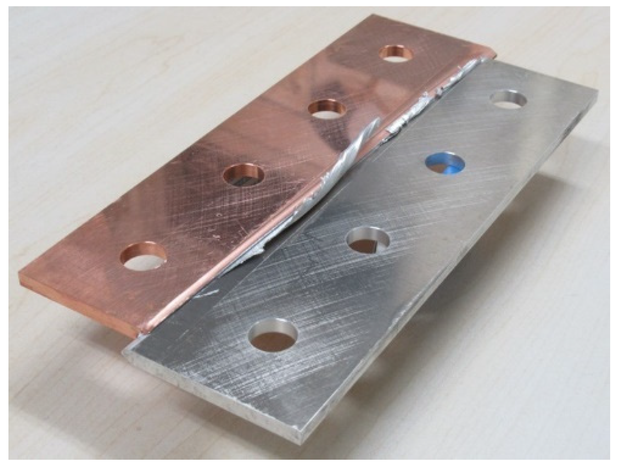
Joining of Copper and Aluminum Alloy A6061 Plates at Edges by High-Speed Sliding with Compression

1
Department of Mechanical Engineering, Gifu University, 1-1 Yanagido, Gifu 501-1193, Japan
2
Graduate School of Natural Science and Technology, Gifu University, 1-1 Yanagido, Gifu 501-1193, Japan
*
Author to whom correspondence should be addressed.
Metals 2024, 14(8), 878; https://doi.org/10.3390/met14080878 (registering DOI)
Submission received: 28 June 2024 / Revised: 20 July 2024 / Accepted: 27 July 2024 / Published: 30 July 2024
(This article belongs to the Special Issue New Welding Materials and Green Joint Technology)

Abstract

:
By using the joined or welded materials of dissimilar metals, the characteristics and performance of products and parts can be improved. The combination of copper and aluminum is difficult to weld. In this study, the impact joining of copper C1100 and aluminum alloy A6061-T6 plates at the edges was investigated to explore the appropriate joining conditions. The plates are joined with newly created surfaces generated by the high-speed compressive deformation with sliding motion. The shape near the interface was a tapered trapezoid with a flat top. The joining length in the plate thickness direction was shorter than the plate thickness, and notches were observed near both plate surfaces. The length became slightly longer by setting a larger top width of the C1100 plate than that of A6061-T6. The joint efficiency increased by approximately 10%. Applying the emery paper finish to the surface of the plate eliminated the non-joining result in multiple experiments. The finishing direction is effective only in the longitudinal direction of the plate. In the tensile test on the dumbbell-type specimen with reduced thickness to eliminate notches, most results showed a fracture at the C1100 portion. The estimated temperature rise of the C1100 is more than about 250 K during the impact deformation. Hence, the strength of the A6061-T6 becomes lower than that of C1100 during the process, and the softened layer of aluminum comes out under pressure, resulting in good joining performance.

1. Introduction

Joining technologies of dissimilar metals have been widely investigated to improve their properties and realize new functions of products and parts, etc. Various combinations of metals were examined, mainly in welding, bonding, and mechanical joining methods. Solid-state bonding or cold diffusion bonding can be applied to the joining of dissimilar or similar metals. The surface exposure and the pressure affect the welding strength [1]. A general theoretical model for the bond strength was developed [2]. A thin, brittle oxide surface layer is fractured to create a large new surface by a very large plastic strain. The effect of surface finish on the shear strength at the interface was investigated. Brushing was found to be one of the effective surface preparation methods for cold welding of steel to other metallic materials [3]. The weld strength was calculated using the theoretical model and compared with the experimental result [4]. Finite element modeling using a cohesive zone element based on the microscopic description of solid-state welding was also examined to describe both bonding and debonding processes [5]. Pressure welding was performed for different metals by cold extrusion [6]. Joining methods combined with plastic forming were reviewed, in which the effective parameters were discussed [7]. The effect of temperature on the strength and the formation of joining was investigated on the microscopic scale [8]. Mechanism and future trend of joining by forming was summarized [9].
For performing the bonding continuously, roll bonding was also tested in addition to press bonding [10]. To increase the bonding strength by promoting the diffusion of atoms, a diffusion bonding experiment was performed under high-temperature conditions [11]. Hot isotropic pressing (HIP) is also effective for the joining of the different metals [12]. Cold spot forge welding was recently developed to achieve high productivity and high-strength joining. Observation of the fracture surface and analysis of chemical compositions revealed the fracture morphology of the Fe/Al interface in cold spot forge welding [13]. Demand for aluminum and copper joined products is increasing in electromobility applications. The materials were also joined using large plastic strains under cold conditions. High compressive deformation, equal channel angular pressing, and forging with backward extrusion were tested for joining [14,15,16]. The feasibility of overlap bonding of pure copper and aluminum alloy by cold spot forge welding was also investigated [17]. The wider joined area can be obtained by explosive welding of the copper and aluminum plates [18].
For the joining of the various combinations of dissimilar metals, friction stir welding (FSW) is available, in which the plates are butted or stacked, and the rotation tool is controlled to move along the path. There are many industrial examples. The evolution of the intermetallic components has a strong effect on the joint strength of the boundary of dissimilar aluminum materials and the boundary of dissimilar titanium alloys [19,20]. The mechanical and electrical properties of the copper—aluminum interface joined with FSW were investigated [21].
For the joining of copper and aluminum sheets, ultrasonic welding with resistance heating was investigated [22]. The materials join partially for the contact area. Joining at the plate edges cannot be achieved by this method. Mechanical joining has also been investigated and developed for industrial use. Self-piercing rivet was applied to the stacked copper and aluminum sheets [23]. Joining using a similar rivet was tested for aluminum and other metallic materials, e.g., copper and steel parts. The adhesive was applied to the clinching joint, which is a hybrid technique [24].
A laser welding technique was also investigated for the joining of copper and aluminum plates, in which the laser beam was directed to the stacked plates. A large plastic deformation occurs during welding, and there is an unavoidable change in the mechanical properties [25,26]. To achieve joining at the edges of the plates, one of the authors devised the impact joining method, which involved a pair of sheared surfaces obtained by high-speed shear rubbing against each other with compressing force under cold conditions [27,28].
The authors have already shown that pure copper plate and aluminum alloy can be joined by the proposed impact joining method [29]. An example is shown in Figure 1. The plate edges to be joined slide at a high speed with increasing compressive force, which causes a very large plastic deformation for the material near the interface. The joint efficiency distributed along the boundary ranged approximately from 0 to 80%, though efficiency over 50% was available for about half of the boundary. In this case, aluminum foil was generated since the surface layer of the aluminum alloy softened by the temperature rise due to adiabatic plastic deformation and friction coming out by compressive force. The Vickers hardness increases within the range of about 1.5 mm from the joint boundary. The affected zone by the joining process is much smaller compared with that in conventional welding. However, the joining performance is unstable. This implies the slight difference in experimental conditions affects the result.
In the present study, the objective is to explore the appropriate joining conditions for obtaining stable joining and exhibit the joining mechanism by calculation of temperature rise considering large plastic deformation. The dimensions of the plate edge and the surface finish of the test plates varied. The surfaces of the plates to be joined were electric-discharged machined (EDMed) surfaces in the present study. Emery paper finish is expected to yield a similar surface condition, which can be easily applied to the surface of the material. Since this is a challenging joining method, the experimental condition was determined through trial and error. The materials were pure copper C1100-1/4H and an aluminum alloy A6061-T6. The distribution of the joint efficiency was evaluated through the joint boundary by the uniaxial tensile test.

2. Impact Joining Device and Experimental Conditions

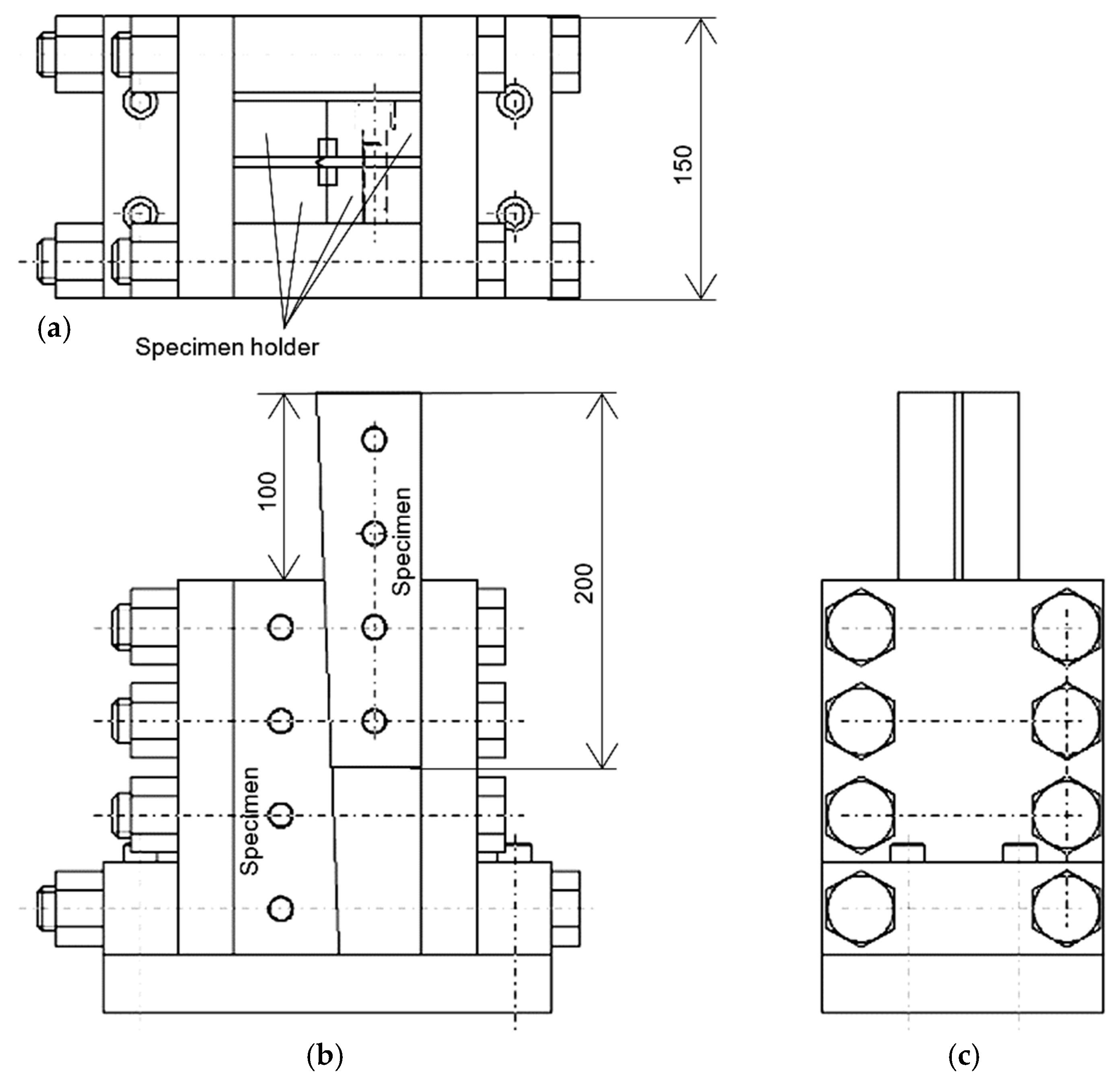
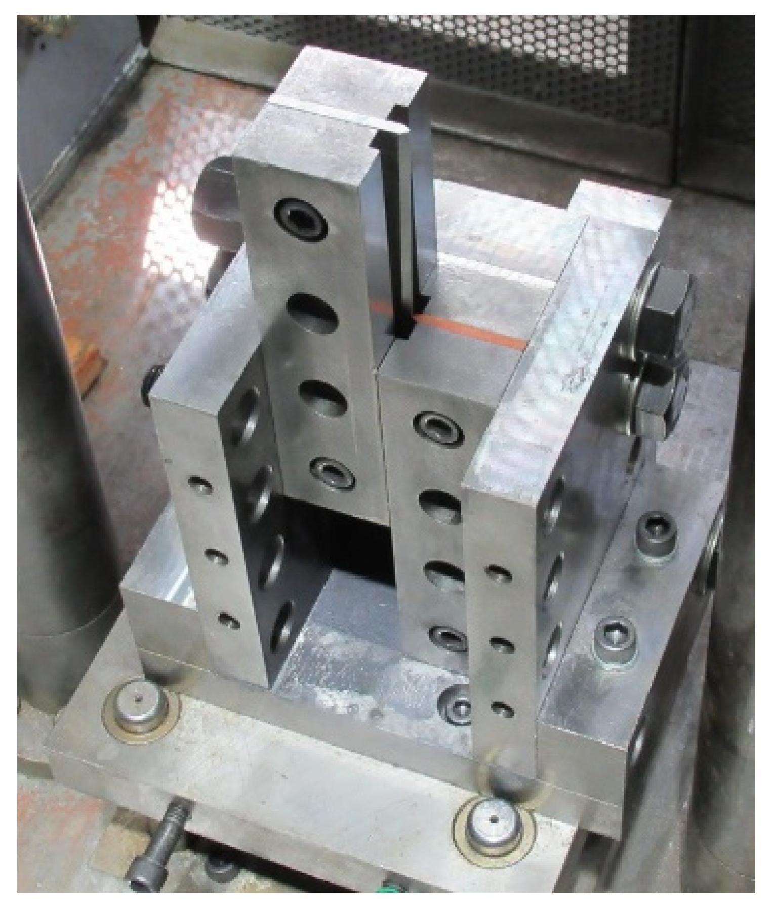
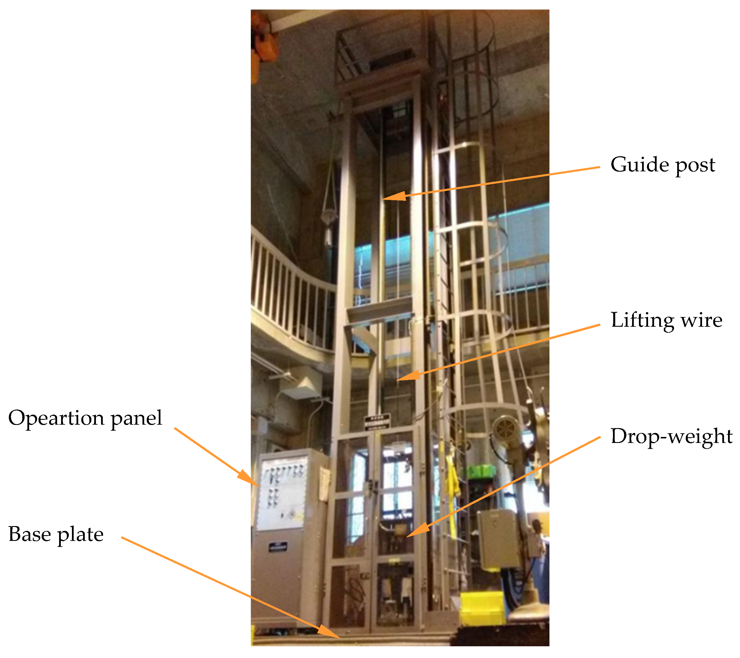
2.1. Impact Joining Device

Schematic of the joining device is shown in Figure 2. The inner view of the device is shown in Figure 3. Each plate is attached to the holder separately in the device. A wedge-shaped test plate was designed. The drop-weight with a mass of 90 kg impacts the top edge of the upper specimen (A6061-T6) holder at a speed of 10 m/s. The impact joining device is installed on the base plate of the impact testing machine with a drop-weight, as shown in Figure 4. When the plate slides at a high speed, the compressive force at the interface increases as the sliding stroke increases since the plate is wedge-shaped.

2.2. Experimental Conditions

The test materials were pure copper C1100-1/4H and an aluminum alloy A6061-T6 with a nominal thickness of 5 mm. The mechanical properties are listed in Table 1. The shape of the test plates to be joined and their alignment are shown in Figure 5. The cross-sectional shape near the sliding interface is a 60° tapered trapezoid with a flat top to concentrate plastic deformation. Hence, the sliding motion under compression was expected to produce a newly created surface for joining.
In our previous study [29], the experimental condition in the tip length of the test plate was TC: 1 mm and TAL: 1 mm, as shown in Figure 5. The plates were joined at a length that was approximately 60% the thickness of the plate. To increase the length of this joining length in the thickness of the plate, an increase of the force or pressure to deform the copper is expected to promote the joining behavior. The tip width was increased to Tc: 2 mm on the copper side only.
The tapered edge of the plate was finished with EDM and used as in our previous study. However, as mentioned in Chapter 1, the joining performance varies from experiment to experiment though the condition was set to be similar. Hence, to always keep the surface condition the same, a surface finish with #100 emery paper was applied to the interface. The finishing directions were the longitudinal direction of the plate and the transverse direction. The tip width is set to TC: 2 mm and TAL: 1 mm, as shown in Figure 5.

3. Evaluation of Joint Efficiency

Distribution of joint efficiency along the joint boundary was evaluated. Joint efficiency is the percentage of the strength of the weaker material. Tensile test specimen was prepared by cutting the joined plate perpendicular to the longitudinal direction at 10 mm interval, and the cut face is shown in Figure 6. The numbering starts from 1 at the bottom edge of the C1100.
The joining performance in the previous experimental results is reproduced in Figure 7 [29]. The distribution of the joint efficiency was evaluated for the two cases when the aluminum foil was generated and when it was not. There is a considerable difference in the joining performance between these cases, where it is much better for the case with aluminum foil generation. In addition to such weak joining, there were also results in which partial joining was not even achieved through the interface. The concave surface of C1100 is covered with aluminum, which implies that the joining strength is larger than that of C1100.

4. Experimental Result and Discussion

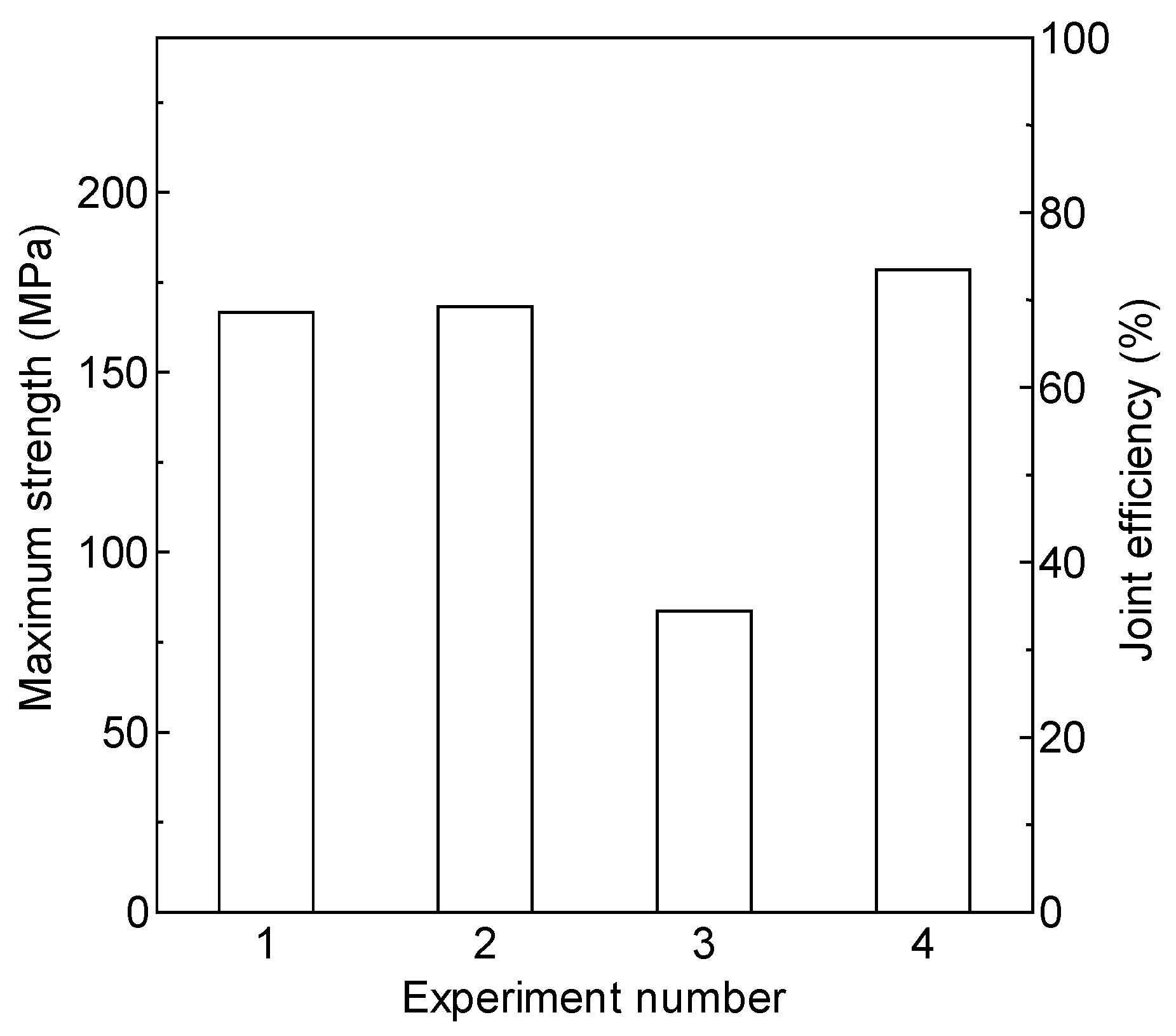
4.1. Effect of Tip Width of Plate Edge of Copper

To increase the joining length in the thickness direction of the plate, the tip width is set to TC: 2 mm and TAL: 1 mm. The compressing force was expected to become larger, promoting the joining performance. Figure 8 shows the cross-section of the joint boundary for EDMed surface condition, where the joined plate is cut at the center in the longitudinal direction of the plate. The tip shape of copper shows a large plastic deformation from trapezoid to concave. The joining performance of these examples is good because the aluminum foil was formed.
The measured joined length in the thickness of the plate is 3.05 mm in Figure 8a or 3.22 mm in Figure 8b. The variation in the joining strength is large along the joint boundary, as shown in Figure 9. The reason for the low strength in No. 3~6 is that the sliding length is short. Hence, the aluminum does not soften. The reason for No. 16 is unknown, though it is presumably due to non-uniform surface conditions. It is convenient to evaluate the performance by taking the average of the 10 largest values, as shown in Figure 10. By increasing the tip width, the average joining strength increased by approximately 10% from 174.4 MPa to the minimum value of 189.0 MPa (average value of three experiments: 194.5 MPa). There is a weak spot in No. 16; however, the strength of No. 7 to 9 is improved.

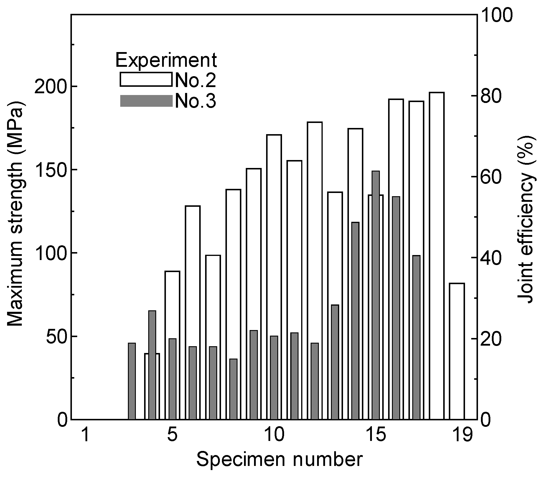
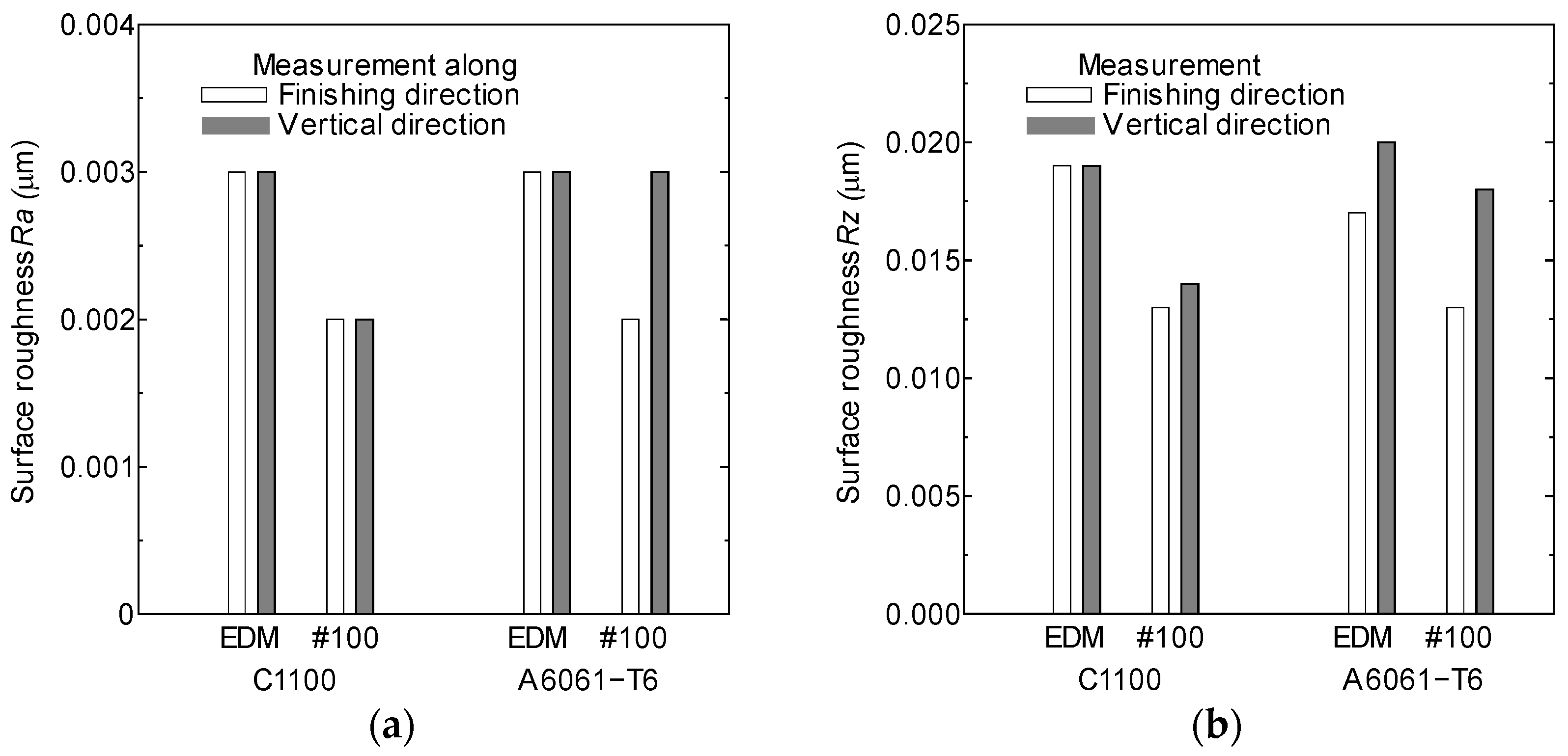
4.2. Effect of Emery Paper Finish

Emery paper finish was applied to the interface surface of both materials. The tip width is set to TC: 2 mm and TAL: 1 mm. The finishing direction is the longitudinal or transverse direction of the test plate. An example of the joined plate is shown in Figure 11. Emery paper of #100 was used. The finishing direction was the longitudinal direction of the test plate. It is observed that the aluminum foil protrudes from the joint boundary.
For the condition with a surface finish in the longitudinal direction, five joining experiments were performed. Joining was achieved in all tests. The strength and joint efficiency from the first to fourth experiments are shown in Figure 12, where they are averaged for the largest 10 values. There is no data for the fifth experiment because the dumbbell-type specimens were cut from the joined plate. The strength is weak in the No. 3 experiment. From these multiple experiments, the effect of emery paper finish is not always enough to obtain high strength. However, it should be noted that the emery paper finish is found to be effective in preventing the non-joining result, which was often seen in the case with the EDMed surface of the test plate, as mentioned above.
The distribution of the maximum strength and joint efficiency in Nos. 2 and 3 experiments is shown in Figure 13. Compared to the weak case shown in Figure 7a, the strength is significantly improved in the weak case. Figure 14 shows the distribution of the maximum strength and the joint efficiency when the #100 emery paper is applied in the transverse direction of the plate. A very partial joining is observed. Therefore, the longitudinal finishing direction is found appropriate. The effect of the particle size of the emery paper will be examined in our further work.
The joined boundary is not complete to the thickness of the plate, as shown in Figure 8. To evaluate the strength of the actual joint boundary, the dumbbell-type tensile test specimen with a thickness of 3 mm was cut from the 5th joined plate, as shown in Figure 15a. The notched portions near both surfaces of the plate were eliminated. The straight length of the dumbbell-type specimen is 40 mm, and the width is 10 mm. The interface was finished by applying #100 emery paper in the longitudinal direction before the joining experiment. As shown in Figure 15b, six specimens show the fracture at C1100. The joint efficiency is 88.9% for the No. 1 specimen, and it is 99.8% for the No. 4 specimen. A joint efficiency of 100% was achieved using the impact joining method.

4.3. Deformation Process Achieving Strong Joint

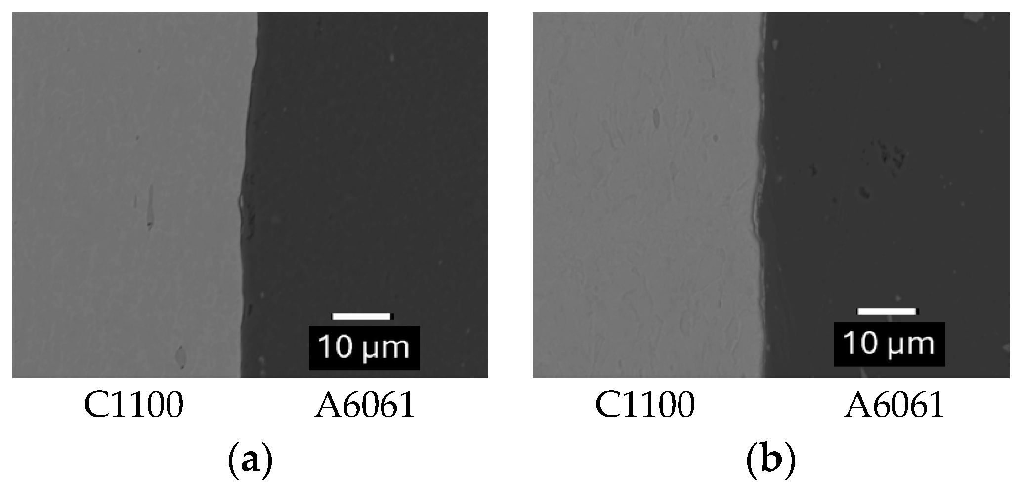
4.3.1. Formation of Aluminum Foil

The cross-section of the joint boundary at the center of the joined plate is shown in Figure 16. Both tip widths of the test plates were 1 mm. The tip of the A6061-T6 plate penetrates the C1100 edge, where the newly created surface is very large. Aluminum foil is clearly visible in the good joining; thus, the tip is more rounded. From the left photograph, the length along the groove profile of C1100 is about 6 mm. The surface expansion is also about six times, considering the initial width of 1 mm. Hence, at least the plastic strain can be estimated to be ln6 = 1.8.
The plastic deformation is a plane strain deformation in which the strain in the longitudinal direction of the plate is 0. Hence, the equivalent plastic strain is ε ¯ = 2.1 . In the calculation of approximate temperature rise, assuming that the stroke when aluminum foil is generated is 80% of the total stroke, the equivalent plastic strain at that time may be estimated to be ε ¯ = 1.7 .
The sliding length at the interface between the test plates was about 90 mm, as shown in Figure 1. The time required for dropping weight with an initial velocity of 10 m/s to stop at 90 mm is calculated to be 0.018 s. The average strain rate of the material is ε ¯ ˙ = 1.7 / 0.018 = 94 /s. Considering the adiabatic plastic deformation, the temperature rise of the material is roughly calculated as follows: using the strain rate sensitivity exponent m = 0.07 of this material, the effective stress σ ¯ = 443 ε ¯ 0.249 ε ¯ ˙ 0.07 = 695 MPa is obtained [30].
The temperature rise T is calculated in the following equation.
T = η ρ C v 0 ε ¯ σ ¯ d ε ¯
It is adequate that the constant stress of σ ¯ = 695 MPa and strain of ε ¯ = 1.7 are used as rough calculations. The density of copper is ρ = 8900 kg/m3, and the specific heat is c v = 385 J/(kg·J). Since it is very difficult to evaluate the temperature, assuming a slightly low conversion efficiency η = 0.6 , the temperature rise of copper near the boundary is calculated to be T = 207 K [31]. Furthermore, the heat generated by friction also elevates the temperature of both materials near the interface. It is probable that a very thin surface layer could rise by more than 250 K, though calculation of the temperature rise due to friction is also difficult.
The strain rate dependence of A6061 is almost negligible even at a strain rate of 1000/s, and the yield strength can be assumed constant at room temperature [32]. When the actual contact area ratio between copper and aluminum alloy is sufficiently large, it is reasonable to assume that the temperature of the extremely thin layer near the surface of the aluminum alloy is close to the surface temperature of the copper. The yield stress of pure copper decreases by approximately 25% when the temperature rises by 200 K from room temperature [33]; on the other hand, A6061 decreases by approximately 40% [32]. The initial yield stress of A6061-T6 is approximately 220 MPa at room temperature. After some amount of plastic deformation with frictional sliding, the yield stress of A6061-T6 becomes lower than that of C1100. Therefore, the very thin surface layer of the A6061-T6 plastically deforms to generate a foil.

4.3.2. Effect of Surface Finish on Joining Performance

The images of the surface profile obtained with a 3D microscope (Keyence VR3000, Osaka, Japan) are shown in Figure 17 for those of EDMed and finished with #100 emery paper. The size of the surface profile is 1.4 mm × 1.9 mm. The color scale is common to all profiles. No orientation is observed on the EDMed surfaces of either material. On the surface finished with #100 emery paper, scratching marks are observed, especially clearer in A6061-T6.
The surface roughness of Ra and Rz are graphically shown in Figure 18. In both Ra and Rz, the surface roughness of the EDMed surface is larger than that of the #100 emery paper finished surface. The orientation in Ra is slightly larger in A6061-T6, though the value is close to the accuracy limit of the measuring device. On the other hand, in Rz, the orientation for the surface finish with #100 emery paper is larger in the transverse direction. It is noted that a very clear difference can be visually observed in the surface images shown in Figure 17. Considering the sliding contact behavior of the materials in the joining process, the actual contact state is probably more intermittent when the sliding direction is perpendicular to the finishing direction of emery paper. Heat transfer from the heated copper to the aluminum is impeded. Therefore, the A6061-T6 does not experience much temperature rise. Regarding the EDMed surface, there were results both with and without joining, as stated above. This is also presumed to be due to subtle differences in the surface texture.
Figure 19 shows the backscattered electron image near the joint boundary. The intensity of the backscattered electrons is larger in copper as the atomic number of the constituent atoms in the specimen is larger. In the good joining, the contrast changes rapidly across the boundary. On the other hand, in the poor joining, there is a thin layer of about 1~2 µm with a mixture of copper and aluminum at the boundary. This picture also proves that the surface finish in the transverse direction is not suitable for joining.

5. Conclusions

The impact joining of C1100 and A6061-T6 plates was investigated to explore the appropriate joining conditions for obtaining stable joining. The cross-sectional shape of the test plate near the sliding interface is a tapered trapezoid with a flat top surface. The materials are compressed with sliding motion under impact conditions. The following conclusions are obtained:
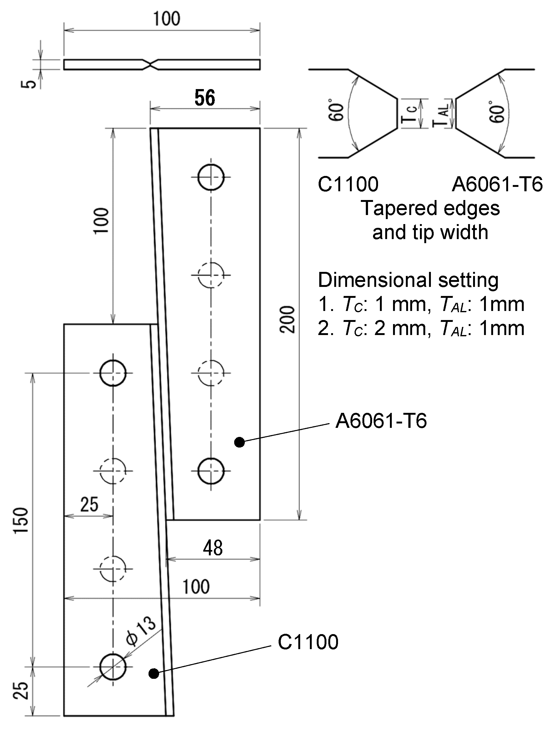
  • The joining is not achieved throughout the thickness of the plate. There are notched portions near both surfaces. When the tip width of the C1100 is set larger than that of A6061-T6, the joined length in the thickness of the plate becomes larger by approximately 6%, and the average joining strength increases by approximately 10%.
  • Non-joining result was often obtained in using the EDMed surface of the test plate. By applying the emery paper finish on the EDMed surface, non-joining result was prevented in the multiple experiment. The finishing direction is found effective only in the longitudinal direction of the plate. Joint strength is very weak for the transverse direction.
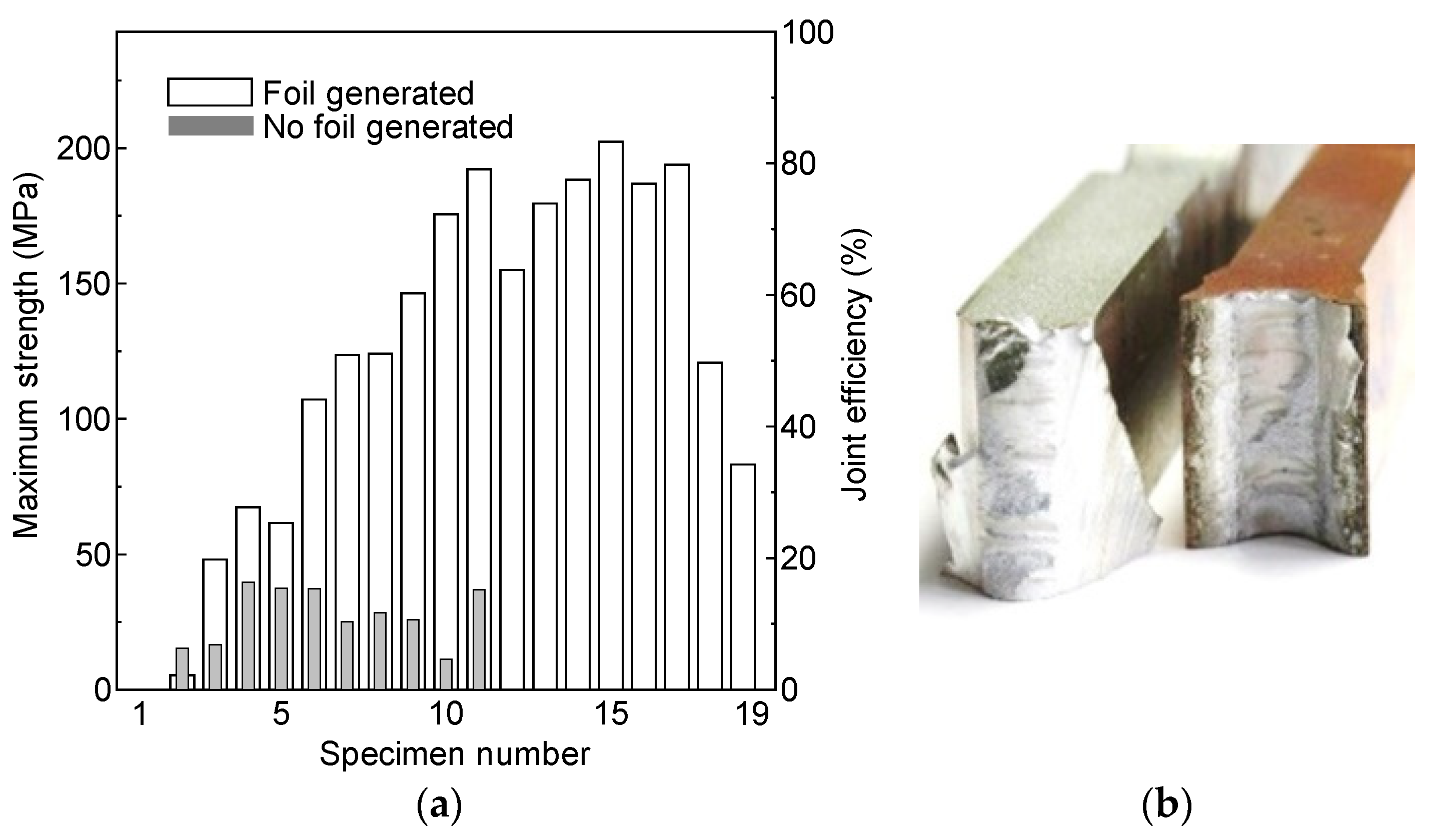
  • A dumbbell-type tensile test specimen was prepared from a joined plate in which the notched portions were eliminated by reducing the thickness from 5 to 3 mm. Six of the eight specimens showed a fracture at C1100, and the joint efficiency was 100%. The joint efficiency for the remaining two cases was 88.9% and 99.8%, which is relatively good.
  • The temperature rise of the C1100 was calculated considering the expansion of surface area, strain rate sensitivity, etc. The temperature would probably rise by more than 250 K during high-speed compression with sliding motion. Therefore, due to that the strength of the A6061-T6 becomes lower than that of C1100, the softened aluminum surface layer is protruded to generate foil.

Author Contributions

Conceptualization, M.Y.; methodology, M.Y., Y.N. and A.I.; investigation, M.Y., Y.N., A.I. and M.N.; writing—review and editing, M.Y. and M.N. All authors have read and agreed to the published version of the manuscript.

Funding

This research received no external funding.

Data Availability Statement

The original contributions presented in the study are included in the article, further inquiries can be directed to the corresponding author.

Conflicts of Interest

The authors declare no conflicts of interest.

References

  1. Bay, N. Mechanisms producing metallic bonds in cold welding. Weld. Res. Suppl. 1983, 62, 137–142. [Google Scholar]
  2. Bay, N.; Clemensen, C.; Juelstorp, O. Bond Strength in cold roll bonding. Ann. CIRP 1985, 34, 221–224. [Google Scholar] [CrossRef]
  3. Zhang, W.; Bay, N. Cold welding-Experimental investigation of the surface preparation methods. Welding J. 1997, 76, 326–330. [Google Scholar]
  4. Zhang, W.; Bay, N. Cold welding theoretical modeling of the weld formation. Welding Res. Suppl. 1997, 10, 417–430. [Google Scholar]
  5. Khaledi, K.; Rezaei, S.; Wulfinghoff, S.; Reese, S. Modeling of joining by plastic deformation using a bonding interface finite element. Int. J. Solid Struct. 2019, 160, 68–79. [Google Scholar] [CrossRef]
  6. Wagener, H.W.; Haats, J. Pressure welding of corrosion resistant metals by cold extrusion. J. Mater. Proc. Technol. 1994, 45, 275–280. [Google Scholar] [CrossRef]
  7. Groche, P.; Wohletz, S.; Mann, A.; Krech, M.; Monnerjahn, V. Conjoint forming–technologies for simultaneous forming and joining. Mater. Sci. Eng. 2016, 119, 012025. [Google Scholar] [CrossRef]
  8. Wohletz, S.; Groche, P. Temperature influence on bond formation in multi-material joining by forging. Procedia Engng. 2014, 81, 2000–2005. [Google Scholar] [CrossRef]
  9. Groche, P.; Wohletz, S.; Brenneis, M.; Pabst, C.; Resch, F. Joining by forming-A review on joint mechanisms, applications and future trends. J. Mater. Process. Technol. 2014, 214, 1972–1994. [Google Scholar] [CrossRef]
  10. Wu, H.Y.; Lee, S.; Wang, J.Y. Solid-state bonding of iron-based alloys, steel-brass, and aluminum alloys. J. Mater. Proc. Technol. 1998, 75, 173–179. [Google Scholar] [CrossRef]
  11. Huang, Z.; Yanagimoto, J. Dissimilar joining of aluminum alloy and stainless steel thin sheets by thermally assisted plastic deformation. J. Mater. Proc. Technol. 2015, 225, 393–404. [Google Scholar] [CrossRef]
  12. Loh, N.L.; Wu, Y.L.; Khor, K.A. Shear bond strength of nickel/alumina interfaces diffusion bonded by HIP. J. Mater. Proc. Technol. 1993, 37, 711–721. [Google Scholar] [CrossRef]
  13. Yamagishi, H. Tensile strength and fracture morphology of Fe/Al solid-state bonding interface obtained by forge welding: Effect of oxide scale and estimation of the bond strength of each phase. Metall. Mater. Trans. 2022, 53A, 4064–4080. [Google Scholar] [CrossRef]
  14. Pawlicki, M.; Drenger, T.; Pieszak, M.; Borowski, J. Cold upset forging joining of ultra-fine-grained aluminium and copper. J. Mater. Proc. Technol. 2015, 223, 193–202. [Google Scholar] [CrossRef]
  15. Eivani, A.R.; Mirzakoochakshirazi, H.R.; Jafarian, H.R. Investigation of joint interface and cracking mechanism of thick cladding of copper on aluminum by equal channel angular pressing (ECAP). J. Mater. Res. Technol. 2020, 9, 3394–3405. [Google Scholar] [CrossRef]
  16. Matsumoto, R.; Hashimoto, K.; Utsunomiya, H. Improvement in bonding strength by applying circumferential sliding in cold copper/aluminum forge-bonding. J. Mater. Proc. Technol. 2022, 307, 117685. [Google Scholar] [CrossRef]
  17. Yamagishi, H. Cu/Al dissimilar cold spot forge welding: Effects of bonding temperature and reduction ratio on joint strength and reaction layer growth. Metall. Mater. Trans. 2023, 54A, 3519–3536. [Google Scholar] [CrossRef]
  18. Kaya, Y. Investigation of copper-aluminium composite materials produced by explosive welding. Metals 2018, 8, 780. [Google Scholar] [CrossRef]
  19. Puentes, S.; Serrano, R.F.; Gonzalez-Doncel, G.; Hattel, J.H.; Mishin, O.V. Microstructure and mechanical properties of friction stir welded AA6061/AA6061 + 40 vol% SiC plates. Metals 2021, 11, 206. [Google Scholar] [CrossRef]
  20. Ji, Y.; Wu, S.; Zhao, D. Microstructure and mechanical properties of friction welding joints with dissimilar titanium alloys. Metals 2016, 6, 108. [Google Scholar] [CrossRef]
  21. Eslami, N.; Harms, A.; Deringer, J.; Fricke, A.; Böhm, A. Dissimilar friction stir butt welding of aluminum and copper with cross-section adjustment for current-carrying components. Metals 2018, 8, 661. [Google Scholar] [CrossRef]
  22. Yang, J.; Cao, B. Investigation of resistance heat assisted ultrasonic welding of 6061 aluminum alloys to pure copper. Mater. Design 2015, 74, 19–24. [Google Scholar] [CrossRef]
  23. He, X.; Zhao, L.; Deng, C.; Xing, B.; Gu, F.; Ball, A. Self-piercing riveting of similar and dissimilar metal sheets of aluminum alloy and copper alloy. Mater. Design 2015, 65, 923–933. [Google Scholar] [CrossRef]
  24. Lei, L.; He, X.; Zhao, D.; Zhang, Y.; Gu, F.; Ball, A. Clinch-bonded hybrid joining for similar and dissimilar copper alloy, aluminium alloy and galvanized steel sheets. Thin-Walled Struct. 2018, 131, 393–403. [Google Scholar] [CrossRef]
  25. Mathivanan, K.; Plapper, P. Laser welding of dissimilar copper and aluminum sheets by shaping the laser pulses. Procedia Manufact. 2019, 36, 154–162. [Google Scholar] [CrossRef]
  26. Dimatteo, V.; Ascari, A.; Liverani, E.; Fortunato, A. Experimental investigation on the effect of spot diameter on continuous-wave laser welding of copper and aluminum thin sheets for battery manufacturing. Opt. Laser Technol. 2022, 145, 107495. [Google Scholar] [CrossRef]
  27. Yamashita, M.; Shibuya, T.; Nikawa, M. Impact joining of metallic sheets and evaluation of its performance. Mater. Res. Proc. 2019, 13, 91–96. [Google Scholar] [CrossRef]
  28. Yamashita, M.; Iwatsuka, T.; Taguchi, H.; Nikawa, M. Impact joining of pure copper C1100 and aluminum alloy A6061-T6 plates at edges. Metals 2022, 12, 1565. [Google Scholar] [CrossRef]
  29. Yamashita, M.; Imayoshi, A.; Nikawa, M. Joining of metal plates at edges by high-speed sliding with compression. In Proceedings of the 14th International Conference on the Technology of Plasticity-Current Trends in the Technology of Plasticity. ICTP 2023. Lecture Notes in Mechanical Engineering; Springer: Cham, Switzerland, 2023; pp. 19–26. [Google Scholar] [CrossRef]
  30. Yamashita, M.; Gotoh, M.; Fujita, E. Development of drop-hammer compression apparatus with controlled stopping device and its application to bonding test. JSME Int. J. Ser. C 1997, 40, 525–532. [Google Scholar] [CrossRef]
  31. Kapoor, R.; Nemat-Nasser, S. Determination of temperature rise during high strain rate deformation. Mech. Mater. 1998, 27, 1–12. [Google Scholar] [CrossRef]
  32. Scapin, M.; Manes, A. Behavior of Al6061-T6 alloy at different temperatures and strain-rates: Experimental characterization and material modelling. Mater. Sci. Eng. A 2018, 734, 318–328. [Google Scholar] [CrossRef]
  33. Ogar, P.; Ugryumov, E.; Koryakyn, I. The Influence of the mechanical properties of copper at elevated temperatures on the tightness of the sealing joint. Mater. Today: Proc. 2021, 38, 1764–1768. [Google Scholar] [CrossRef]
Figure 1. Copper (left) and aluminum (right) joined plate.
Metals 14 00878 g001
Figure 2. Schematic of impact joining device (unit: mm): (a) upper view, (b) front view, and (c) side view.
Metals 14 00878 g002
Figure 3. Inner view of impact joining device.
Metals 14 00878 g003
Figure 4. Impact testing machine with drop-weight (Tokyo testing machine, Tokyo, Japan).
Metals 14 00878 g004
Figure 5. Initial configuration and dimensions of test plates (some test pieces have two central holes) (unit: mm).
Metals 14 00878 g005
Figure 6. Tensile test specimen numbered from the bottom side.
Metals 14 00878 g006
Figure 7. Joining performance in setting in TC: 1 mm, TAL: 1 mm: (a) joint efficiency along the joint boundary and (b) fractured specimen.
Metals 14 00878 g007
Figure 8. Cross-section of joint boundary (left: C1100, right: A6061-T6) for different initial tip lengths: (a) TC: 1 mm, TAL: 1 mm and (b) TC: 2 mm, TAL: 1 mm.
Metals 14 00878 g008
Figure 9. An example of joining performance for EDMed surface in TC: 2 mm, TAL: 1 mm.
Metals 14 00878 g009
Figure 10. Averaged value taken for large 10 values for EDMed surface when aluminum foil is generated.
Metals 14 00878 g010
Figure 11. An example of the joined plate in the case with a surface finish in the longitudinal direction.
Metals 14 00878 g011
Figure 12. Joining performance in averaged value for largest 10 values.
Metals 14 00878 g012
Figure 13. Joining performance of experiments No. 2 and 3 shown in Figure 12.
Metals 14 00878 g013
Figure 14. Joining performance in transverse finishing direction.
Metals 14 00878 g014
Figure 15. Tensile test of the joined plate of the 5th experiment: (a) dumbbell-type specimen and (b) result of the tensile test (from left No. 1, 2, 3… specimen).
Metals 14 00878 g015
Figure 16. Enlarged view of joint boundary for EDMed surface: (a) foil generated (good joining) and (b) no foil generated (poor joining).
Metals 14 00878 g016
Figure 17. Surface profile under various conditions: (a) EDMed surface and (b) #100 emery paper finish (fin-ishing direction: front left to back right).
Metals 14 00878 g017
Figure 18. Surface roughness measured in two directions: (a) surface roughness Ra and (b) surface roughness Rz.
Metals 14 00878 g018
Figure 19. Backscattered electron image near the joint boundary (surface finish with #100 emery paper): (a) good joining (finishing direction: longitudinal) and (b) poor joining (transverse).
Metals 14 00878 g019
Table 1. Mechanical properties of test materials (thickness: 5 mm).
MaterialUltimate Tensile Strength (MPa)C (MPa)n-Value
C1100-1/4H2434430.249
A6061-T63224310.084
Plastic property: σ = C ε n .
Disclaimer/Publisher’s Note: The statements, opinions and data contained in all publications are solely those of the individual author(s) and contributor(s) and not of MDPI and/or the editor(s). MDPI and/or the editor(s) disclaim responsibility for any injury to people or property resulting from any ideas, methods, instructions or products referred to in the content.

