Article

Research on the Macro-Cell Corrosion Behavior of Alloyed Corrosion-Resistant Steel for a Transmission Line Steel Structure under a Chloride Corrosion Environment

1
State Grid Wuxi Power Supply Company, Wuxi 214000, China
2
College of Materials Science and Engineering, Hohai University, Nanjing 211100, China
*
Authors to whom correspondence should be addressed.
Metals 2024, 14(8), 879; https://doi.org/10.3390/met14080879 (registering DOI)
Submission received: 4 July 2024 / Revised: 23 July 2024 / Accepted: 26 July 2024 / Published: 30 July 2024
(This article belongs to the Special Issue Advances in the Design and Behavior Analysis of High-Strength Steels)

Abstract

:
“The article investigates the macro-cell corrosion behavior and corrosion resistance when the alloyed steel and the carbon steel are used together because the traditional carbon steel is difficult to meet the corrosion resistance and durability of the steel structure of the transmission line in the marine environment.” In this paper, a new type of Cr-alloyed corrosion-resistant steel (00Cr10MoV) is used to partially replace carbon structural steel in order to meet the actual needs of corrosion resistance and service life improvement of steel structures for offshore transmission lines. It is important to systematically study the macro-cell corrosion behavior of combinations of the same type of steel and dissimilar steel, induced by the chloride concentration difference in simulated concrete solutions, and employ electrochemical testing methods to scientifically evaluate the corrosion resistance of steel after macro-cell corrosion. The aim is to study and evaluate the macro-cell corrosion behavior of alloyed corrosion-resistant steel and to lay a foundation for its combined use with carbon steel in a chloride corrosion environment to improve the overall corrosion resistance and service life. Under the same concentration difference, the macro-cell corrosion of the alloyed steel combination is milder compared with the carbon steel combination. The corrosion current of the alloyed steel combination at 29 times the concentration difference is only 1/10 of the carbon steel combination. Moreover, at 29 times the concentration difference, the macro-cell corrosion potential of dissimilar steel is only 1/6 of the combined potential of carbon steel combination under the same concentration difference, and the corrosion current is only 1/10 of that of the carbon steel combination.

1. Introduction

With the rapid development of offshore new energy, the construction of new energy power engineering infrastructure such as offshore photovoltaic and wind power is endless. In addition, the demand for electricity in offshore industries has also shown a rapidly growing trend with the development of the marine economy. The power transmission of new energy power generation and the power supply of offshore industry are inseparable from the safe construction and efficient operation and maintenance of the transmission line infrastructure. Transmission towers and steel pipe poles are important components of the infrastructure for long-distance power grid transmission lines. A large amount of steel is needed to ensure their structural strength and operational reliability. Due to a strong corrosive environment such as high salinity and high humidity in the marine environment, the steel materials used in the transmission tower and steel pipe pole structures at sea and offshore are faced with corrosion and oxidation, which reduces their strength and durability, causes damage to the bearing capacity of the structure, and even leads to collapse accidents [1,2,3].
Traditional carbon steel makes it difficult to meet the corrosion resistance and durability requirements of transmission line steel structures in marine environments. The steel structure foundation of transmission lines in direct contact with seawater generally needs to be covered with a concrete protective layer to avoid direct erosion of the steel structure by seawater. However, given the porous structure of concrete, the diffusion of seawater and the transport of chloride ions are difficult to eliminate. Once the chloride ion concentration at the steel/concrete interface exceeds the critical value, it will eventually cause steel corrosion and seriously affect the strength of the structural foundation.
The use of alloyed steel with higher corrosion resistance is an important way to effectively improve the corrosion resistance and service life of the structure. Alloyed corrosion-resistant steel is a kind of steel containing specific alloying elements. It has excellent corrosion resistance and can maintain good service stability for a long time in harsh marine environments. The main alloying elements usually include chromium, nickel, copper, etc. These elements can form a dense oxide or other compound layer, effectively preventing further corrosion of steel. The use of alloyed corrosion-resistant steel in offshore transmission lines can effectively prolong its service life, reduce maintenance and replacement frequency, and reduce maintenance costs throughout the life cycle. The use of corrosion-resistant steel materials can also improve the stability and reliability of transmission lines, reduce the risk of faults and accidents caused by corrosion of steel pipe rods, and ensure the safe operation of transmission lines. However, due to the addition of a certain amount of alloying elements, the production cost of alloyed corrosion-resistant steel is much higher than that of traditional carbon structural steel. In practical engineering applications, based on cost considerations, it is difficult to apply alloyed corrosion-resistant steel to replace carbon structural steel in the whole structure. Generally, alloyed corrosion-resistant steel and carbon steel are used together to account for the comprehensive cost considerations and corrosion resistance requirements. When dissimilar metals are used in conjunction, they will face the potential risk of macro-cell corrosion. In the coupling system of alloyed corrosion-resistant steel and carbon steel, the alloyed steel with high corrosion resistance has the potential to act as the cathode for macro-cell corrosion and accelerate the corrosion of carbon steel as an anode. Therefore, the macro-cell corrosion behavior and corrosion resistance of alloyed corrosion-resistant steel are worthy of attention and research.
Carbon steel possesses excellent mechanical properties and significant price advantages, making it the most widely used steel in engineering applications. However, the insufficient corrosion resistance of carbon steel under corrosive environments is particularly prominent [4,5,6]. Therefore, research on the corrosion of carbon steel is extensive and in-depth, and its macro-cell corrosion research is no exception [7,8]. Stainless steel contains a large amount of alloying elements such as Cr, Ni, and Mo to make alloyed steel with higher corrosion resistance grades. They can be used in critical structural components serving in extremely harsh corrosive environments, such as inland salt lakes and tropical oceans [9,10,11]. Due to the superior corrosion resistance of stainless steel, there is a significant potential difference between them and carbon steel, as well as a greater potential advantage compared with general corrosion-resistant alloyed steel [12,13]. Regarding the inhibition of macro-cell corrosion, Zhu et al. conducted research on macro-cell corrosion for X65 carbon steel and 316 stainless steel in a crevice environment. They found that under crevice conditions, the proper combination of X65 carbon steel and 316 stainless steel had an inhibitory effect on macro-cell corrosion [14,15]. Due to the highly destructive nature of macro-cell corrosion, there is an urgent need for a material capable of addressing this type of corrosion behavior. With excellent corrosion resistance and a relatively higher cost-effectiveness, medium- and low-alloyed steel has become a focal point in corrosion protection research [16,17]. Hao Limin et al. conducted a systematic study on the macro-cellular corrosion of Hastelloy C-276 alloy and 16MnR steel in harsh HCl environments. They found that the corrosion rate of the alloy acting as the cathode was somewhat inhibited, while the corrosion rate of the anode alloy increased significantly. The macro-cell corrosion current between the two gradually stabilized with time [18,19]. Peng et al. conducted an in-depth study on the macro-cellular corrosion behavior of pure titanium and low-alloyed steel 921A in marine environments. They found significant macro-cell corrosion currents between the two, and the increase in temperature accelerated macro-cell corrosion [20,21].
In conclusion, it can be observed that alloyed steel exhibits good corrosion resistance under macro-cell corrosion conditions. However, macro-cell corrosion does not disappear merely because alloyed steel is used. Studies have found that by combining alloyed steel with other types of steel and placing corrosion-resistant alloyed steel in more severe corrosive environments while placing less corrosion-resistant steel in general corrosive environments can weaken macro-cell corrosion [22]. However, there is limited research in this area [23]. Therefore, in the marine environment, with the combination of the excellent characteristics of alloyed steel and low-cost carbon steel, there is a potential research value in protecting steel against macro-cell corrosion, and it also provides more choices and guarantees for the construction and operation of offshore transmission lines. The transmission line steel structure made of alloyed corrosion-resistant steel materials can effectively improve the corrosion resistance and durability of transmission line structures in offshore areas and ensure safe operation and reliable power supply.
In this paper, a new type of Cr-alloyed corrosion-resistant steel (00Cr10MoV) is used to partially replace carbon structural steel in order to meet the actual needs of corrosion resistance and service life improvement of steel structures for offshore transmission lines. The macro-cell corrosion behavior and corrosion resistance of alloyed steel and carbon steel under the cover of a concrete protective layer in the marine chloride ion erosion environment are studied, which provides a research basis for the potential application of 00Cr10MoV alloyed corrosion-resistant steel in offshore transmission line steel structures.

2. Materials and Methods

2.1. Preparation of Steel Samples and Materials

The steel used in this experiment is alloyed steel (model: 00Cr10MoV) and carbon steel (model: 20MnSi) with a diameter of 16 mm, and its main chemical composition is shown in Table 1.
Steel specimens in chloride salt erosion simulated concrete solution: Use an electric discharge wire-cutting machine to cut both types of steel into 5 cm long segments. Then, use an angle grinder to cut a circular groove at one end of the steel segment, which is used to fix the copper wire on the specimen, followed by sandblasting for surface rust removal. After rust removal, clean the surface with acetone to remove surface oil stains and then clean with anhydrous ethanol using ultrasound. Mark the steel samples at 1 cm from both ends after air drying. Fix the copper wire at one end of the steel with a groove. Seal both ends successively in a mold filled with an appropriate amount of epoxy resin. After the epoxy cures, immerse the specimens in the prepared simulated concrete solution for seven days of pre-passivation before conducting immersion experiments.
First, prepare saturated calcium hydroxide solution as the simulated concrete pore solution and pour it into two solution tanks separately. All steel specimens undergo pre-passivation for 7 days. The steel combinations are divided into three types:
(1) Carbon steel–carbon steel connection (control group): Place the prepared two carbon steel specimens in the reaction container, maintaining a certain distance between the two types of steel. On one side with low chloride ion concentration, prepare Cl- concentration of 0.1 mol/L, while on the other side, prepare Cl- concentrations of 0.1 mol/L, 0.5 mol/L, 1 mol/L, 2 mol/L, and 3 mol/L, respectively, forming chloride ion concentration ratios of 1, 5, 10, 20, and 30 (i.e., no concentration difference, 4 times concentration difference, 9 times concentration difference, 19 times concentration difference, and 29 times concentration difference).
(2) Alloyed steel–alloyed steel connection group: Place the prepared alloyed steel specimens separately in the reaction container, maintaining a certain distance between them. On one side with low chloride ion concentration, prepare Cl- concentration of 0.1 mol/L, while on the other side, maintain chloride ion concentration consistent with the carbon steel–carbon steel group.
(3) Carbon steel–alloyed steel combination: Place carbon steel specimens in the solution tank with a chloride ion concentration of 0.1 mol/L. Corresponding alloyed steel specimens are placed in solution tanks with chloride ion concentrations of 0.1 mol/L, 0.5 mol/L, 1 mol/L, 2 mol/L, and 3 mol/L, respectively, on the other side. The distance between the steel is kept constant. The two solutions are connected by a homemade saturated KCl- agar salt bridge, and the distance between the steel is kept consistent. Then, connect the two steel specimens through wire connectors to form a macro-cell corrosion structure with a chloride ion concentration difference.

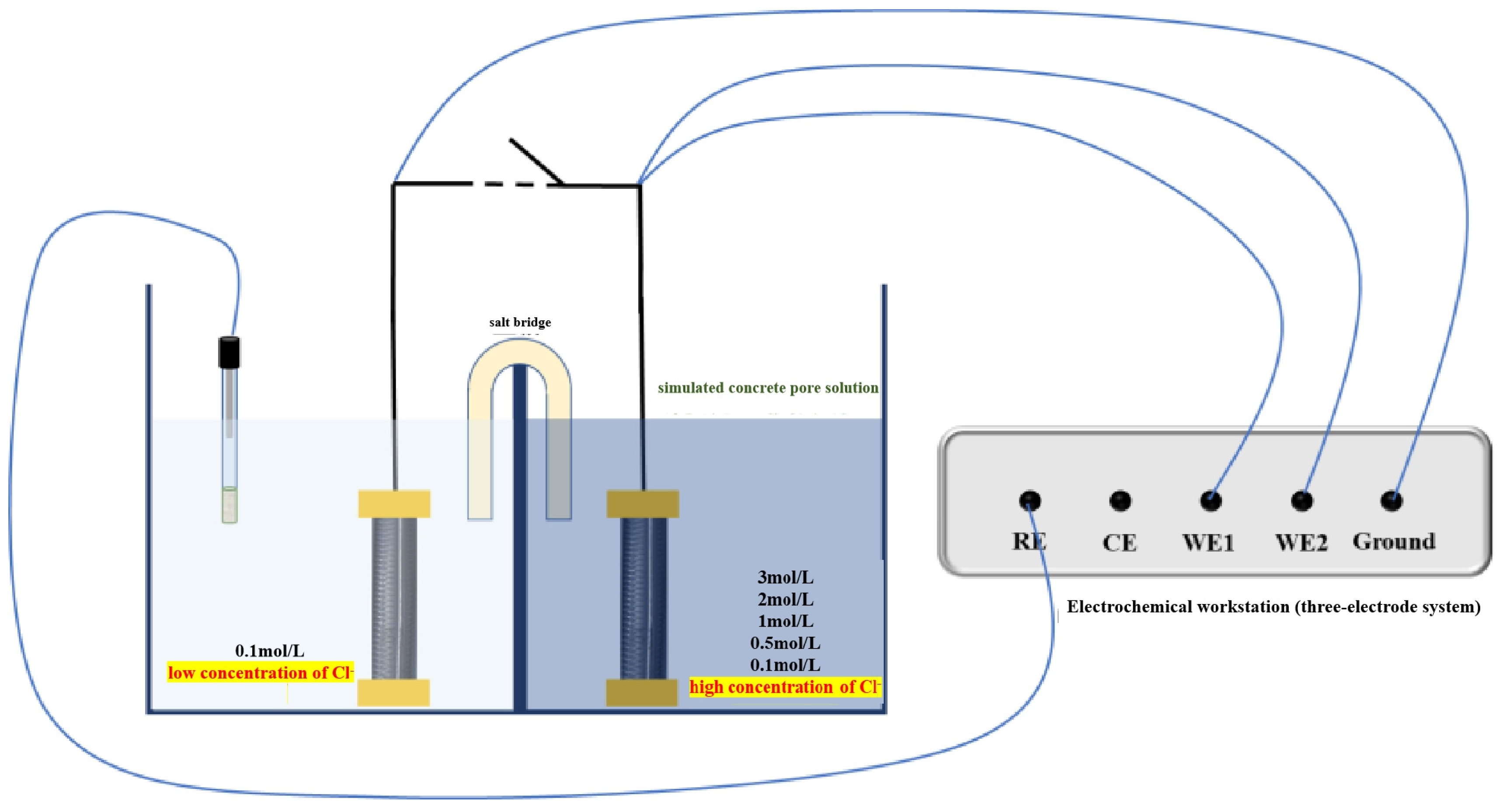
2.2. Electrochemical Testing Techniques

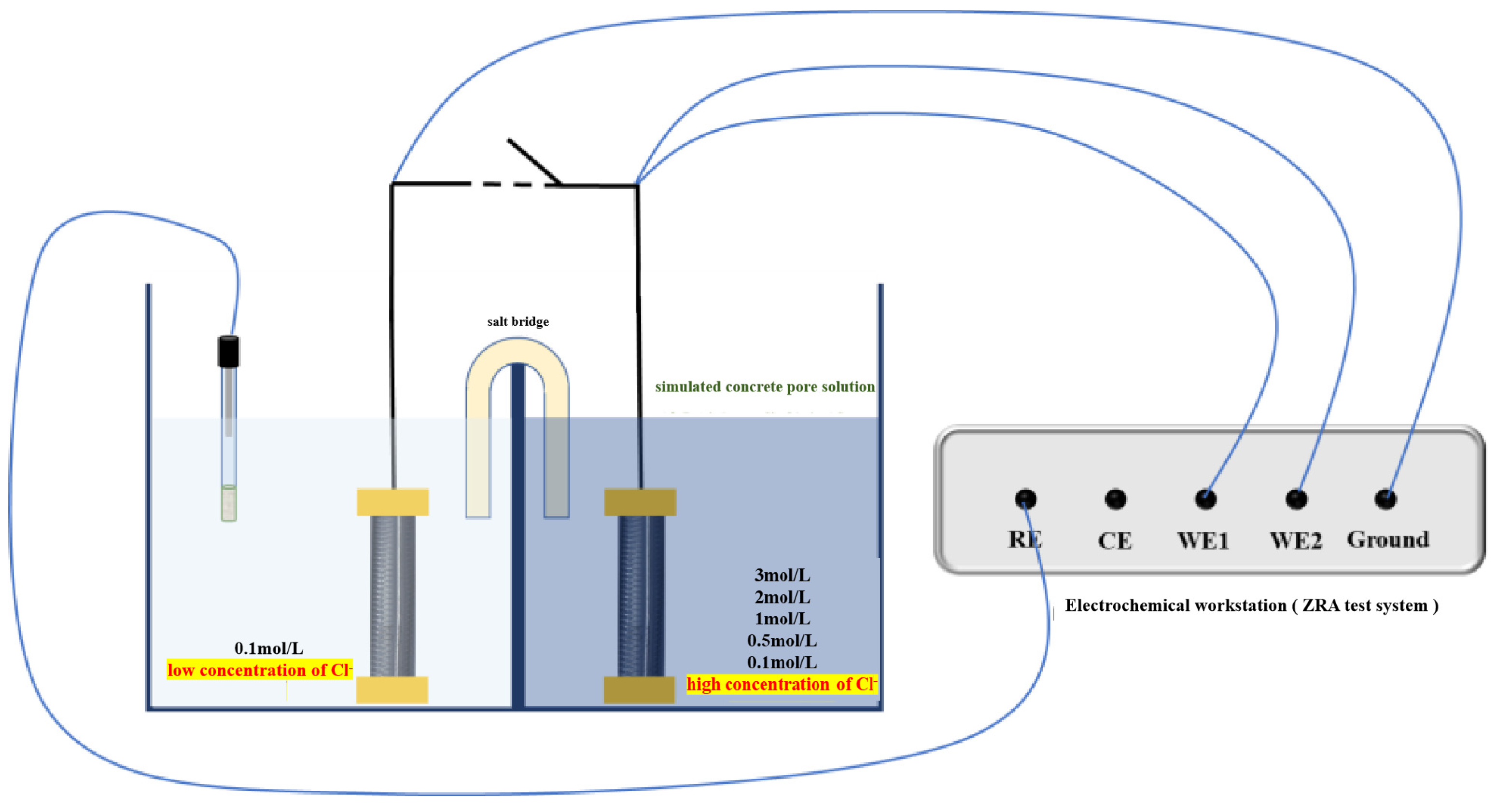
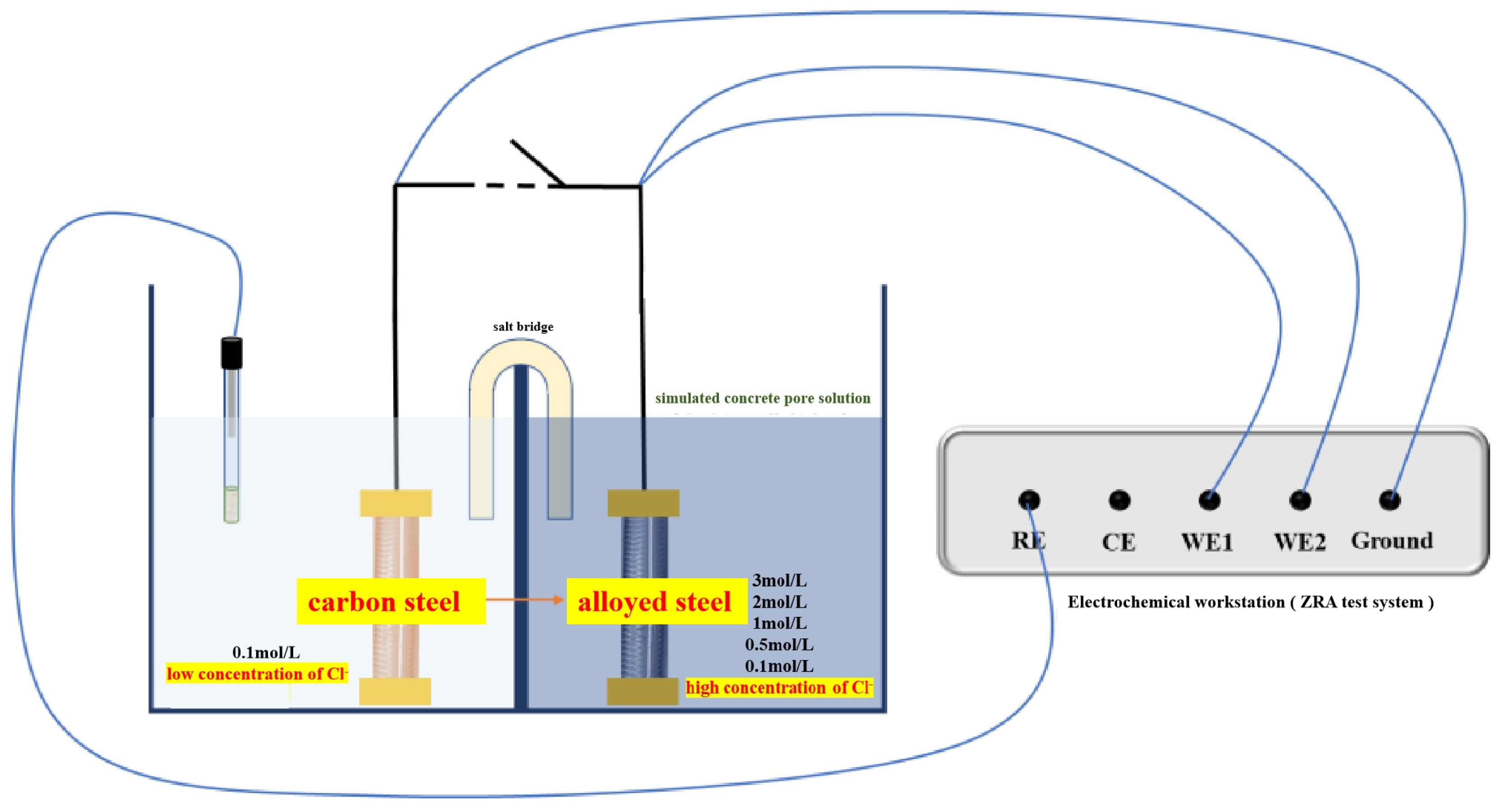
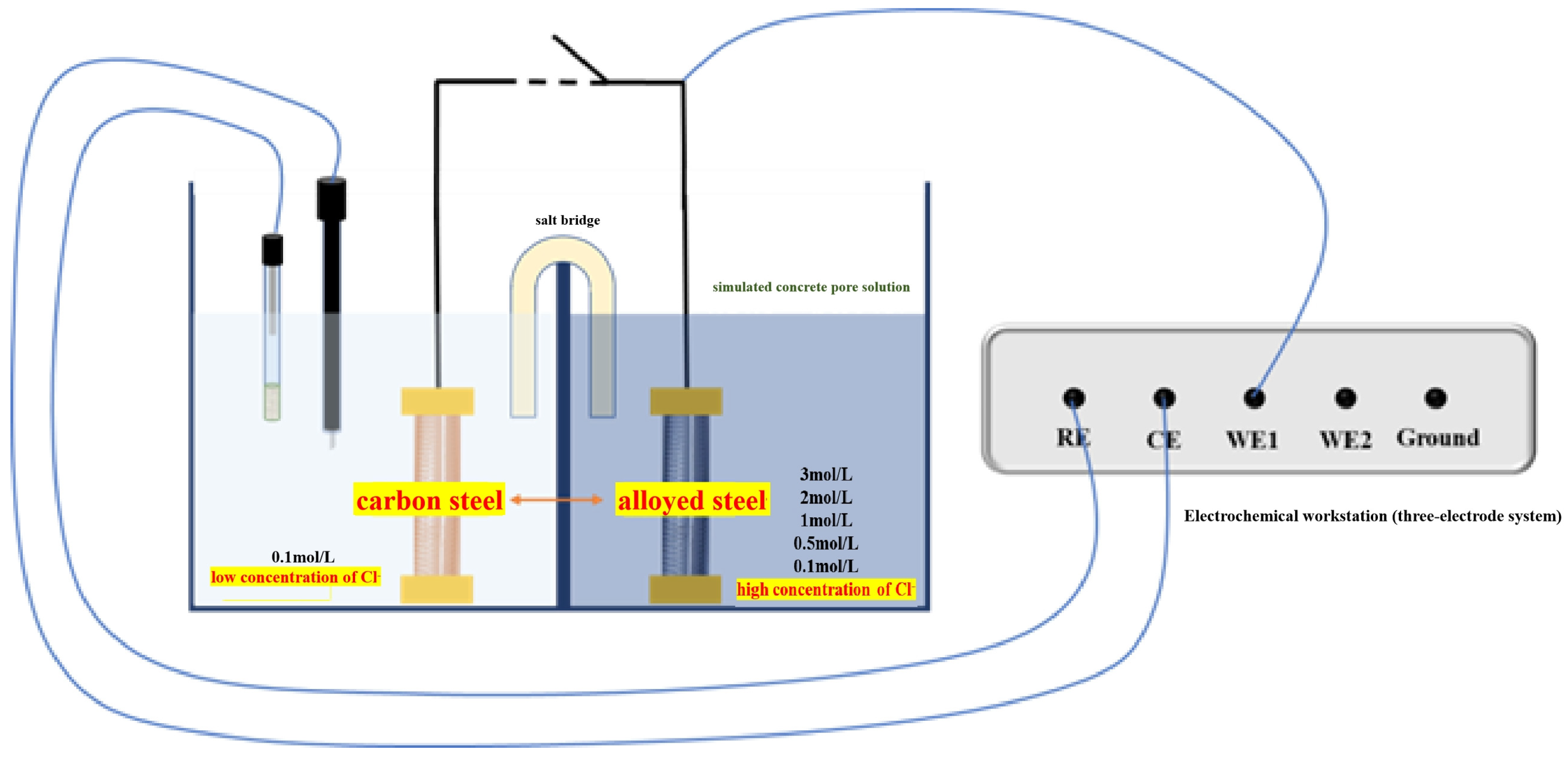
2.2.1. Macro-Cell Corrosion Current and Coupling Potential Testing

The testing of concentration difference macro-cell corrosion current and coupling potential utilizes the ZRA (zero resistance ammeter) module within the PARSTAT 2273 electrochemical workstation produced by the American company Princeton. The testing time is set to 1 h, and readings are recorded once the current–potential curve stabilizes.

2.2.2. Electrochemical Impedance Spectroscopy (EIS) Testing

Electrochemical impedance spectroscopy is a nondestructive corrosion detection method that visually reflects the electrochemical state of metal corrosion through the size of the impedance arc in the spectrum. For EIS testing, three electrodes are placed in the solution of the tested steel, with the open circuit potential used as the initial potential for testing. The frequency range is set from 10−2 to 105 Hz. After testing, the data are saved to obtain impedance complex plots (Nyquist) and phase angle plots (Bode).

2.2.3. Potentiodynamic Polarization (PDP) Testing

Potentiodynamic polarization testing also employs a three-electrode system. The voltage is initially set to the open-circuit potential value minus 0.5 V, and the final voltage is set to 1 V. The scan rate is set to 0.001 mV/s. A sufficient scan range enables obtaining more complete anodic–cathodic polarization curves of the samples.
Both electrochemical impedance spectroscopy and potentiodynamic polarization electrochemical tests were conducted using the CHI660E electrochemical workstation produced by the Chinese company Shanghai Chenhua.

3. Results and Discussion

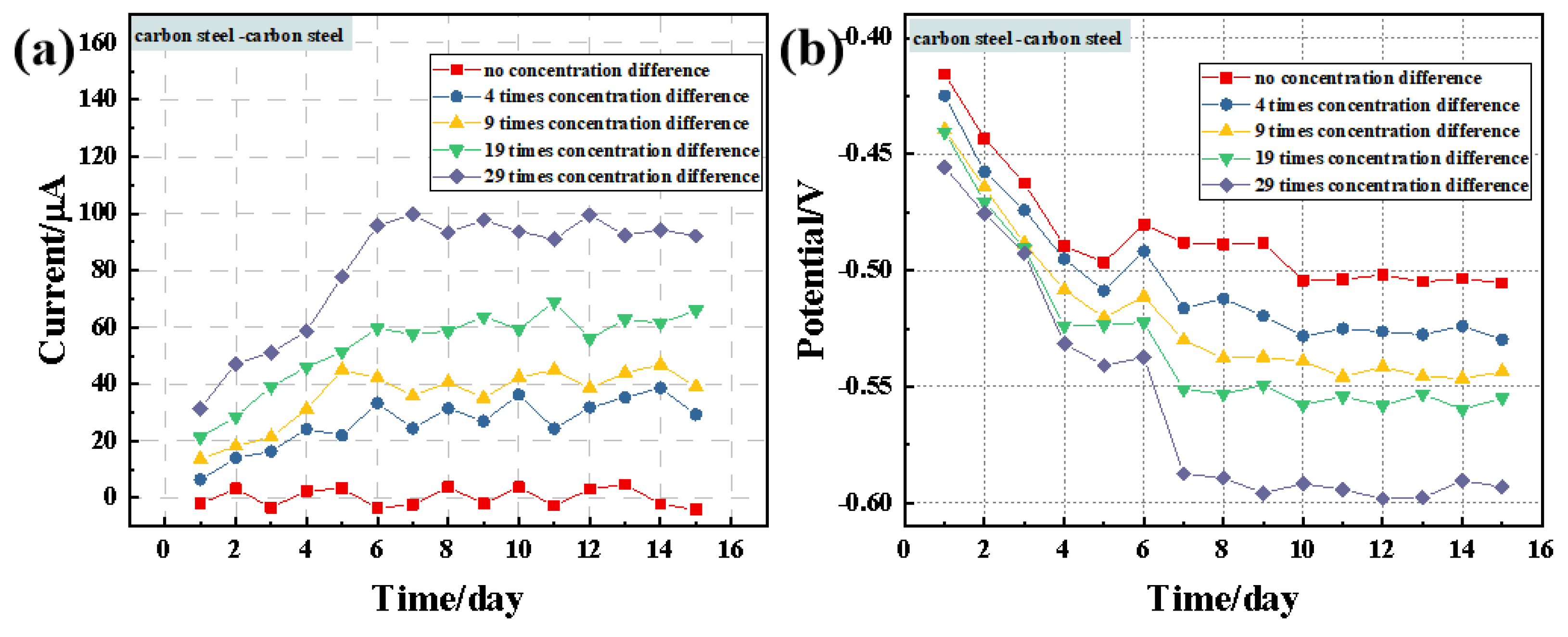
3.1. Macro-Cell Corrosion Induced by the Chloride Ion Concentration Difference for the Same Steel Based on the ZRA Testing

Experimental conditions for macro-cell corrosion induced by a chloride ion concentration difference in the same steel were created by setting two chloride ion concentration difference conditions in the simulated concrete solution. Figure 1 shows a schematic diagram of the experimental setup for macro-cell corrosion induced by chloride ion concentration difference in the same steel and the wiring method for the ZRA testing. The corrosion reaction container is divided into two solution tanks, serving as a low-concentration area (0.1 mol/L Cl) and a high-concentration area (0.1 (no concentration difference), 0.5, 1, 2, and 3 mol/L Cl). Carbon steel combination samples and alloyed steel combination samples are placed on both sides, with the low-concentration area samples set as corrosion cathodes and the high-concentration area samples set as corrosion anodes. At the beginning of corrosion, the sample wires are connected and then disconnected during the ZRA testing. The cathode sample is connected to the ground wire, and the anode steel is connected to two working electrodes (WE1, WE2) and then connected to the reference electrode to increase the data testing of the coupled potential.
The macro-cell corrosion current is the most crucial indicator for assessing the development status of macro-cell corrosion [24]. Figure 2 and Figure 3 depict the time-varying curves of the macro-cell corrosion current and coupling potential for different steel combinations under varying chloride salt concentration difference conditions. As shown in Figure 2a, the macro-cell corrosion current value for carbon steel is relatively small in the initial stages of corrosion. With an increase in corrosion time, the macro-cell corrosion current values for carbon steel combinations under four different chloride ion concentration conditions rapidly rise, reaching dynamic stability by the sixth day [25]. A positive macro-cell corrosion current value indicates that the steel in the high-concentration area acts as the corrosion anode, while the carbon steel in the low-concentration area acts as the corrosion cathode. When the concentration difference is 4 times, the stabilized current values fluctuate between 20 and 30 μA, while at 29 times concentration difference, the stabilized current values fluctuate between 90 and 100 μA, demonstrating a significant impact of the chloride ion concentration difference variation on the macro-cell corrosion current of carbon steel. It is noteworthy that under conditions with no difference, the macro-cell corrosion current values for carbon steel combinations fluctuate around 0 μA with considerable amplitude [26]. The change in sign of the macro-cell corrosion current indicates a mutual transition in the anode–cathode polarity of macro-cell corrosion, suggesting a tendency toward macro-cell corrosion in carbon steel even under conditions of chloride salt erosion without a concentration difference, which may be attributed to the potential difference between the steel on both sides with different corrosion states. From the time-varying curves of the coupling potential in Figure 2b, it is evident that the coupling potential decreases rapidly with increasing corrosion time and begins to stabilize around the 6~7th day. The coupling potential for carbon steel combinations decreases successively with the increasing chloride ion concentration difference, with the steel in the high-concentration area exhibiting a more severe macro-cell corrosion tendency [27]. Under conditions with no concentration difference, the coupling potential remains around −500 mV, while for the 29 times concentration difference, the potential value decreases to around −600 mV.
Figure 3a shows the time-varying curves of macro-cell corrosion current for the alloyed steel combination under different chloride salt concentration difference conditions. Under conditions with no chloride salt concentration difference, the macro-cell corrosion current for the alloyed steel combination fluctuates around 0 μA, with an extremely small amplitude of fluctuation. With an increase in chloride salt concentration difference, the macro-cell corrosion current for the alloyed steel combination exhibits a slow initial increase and stabilizes within a relatively small range of fluctuation after approximately 8 days. When the concentration difference multiples are 4, 9, 19, and 29, the macro-cell corrosion current values for the alloyed steel combination stabilize at around 4 μA, 5 μA, 7 μA, and 11 μA, respectively. It can be observed that in the macro-cell corrosion system induced by the chloride salt concentration difference, the steel in the low-concentration area acts as the corrosion cathode, while the steel in the high-concentration area acts as the corrosion anode. However, the increase in the macro-cell corrosion current for the alloyed steel combination is relatively slow with an increase in the chloride ion concentration difference, indicating that the alloyed steel exhibits strong resistance to macro-cell corrosion under the chloride ion concentration difference conditions [28]. Figure 3b illustrates the time-varying curves of coupling potential for the alloyed steel combination under different chloride salt concentration difference conditions. From the graph, it can be observed that under conditions with no concentration difference, the coupling potential for the alloyed steel remains at a relatively high level, and corrosion for 15 days does not lead to a significant decrease in the coupling potential of the alloyed steel combination. For the other four concentration difference conditions, the coupling potential for the alloyed steel combination gradually shifts to more negative values as the concentration difference multiples increase [29]. Specifically, the coupling potential values are approximately −370 mV, −420 mV, −440 mV, and −460 mV, respectively, and they stabilize dynamically after around 8 days.
The comparison of macro-cell corrosion current and coupling potential between the alloyed steel combination and the carbon steel combination under various chloride ion concentration difference conditions reveals that the macro-cell corrosion current for the alloyed steel combination is significantly lower than that for the carbon steel combination, while the coupling potential is more positive than that for the carbon steel combination. Specifically, at a 29 times chloride salt concentration difference, the macro-cell corrosion current for the alloyed steel combination is only about one-tenth of that for the carbon steel combination, indicating a very slow corrosion rate. This observation intuitively demonstrates the strong resistance capability of alloyed steel against macro-cell corrosion induced by the chloride ion concentration difference [30].

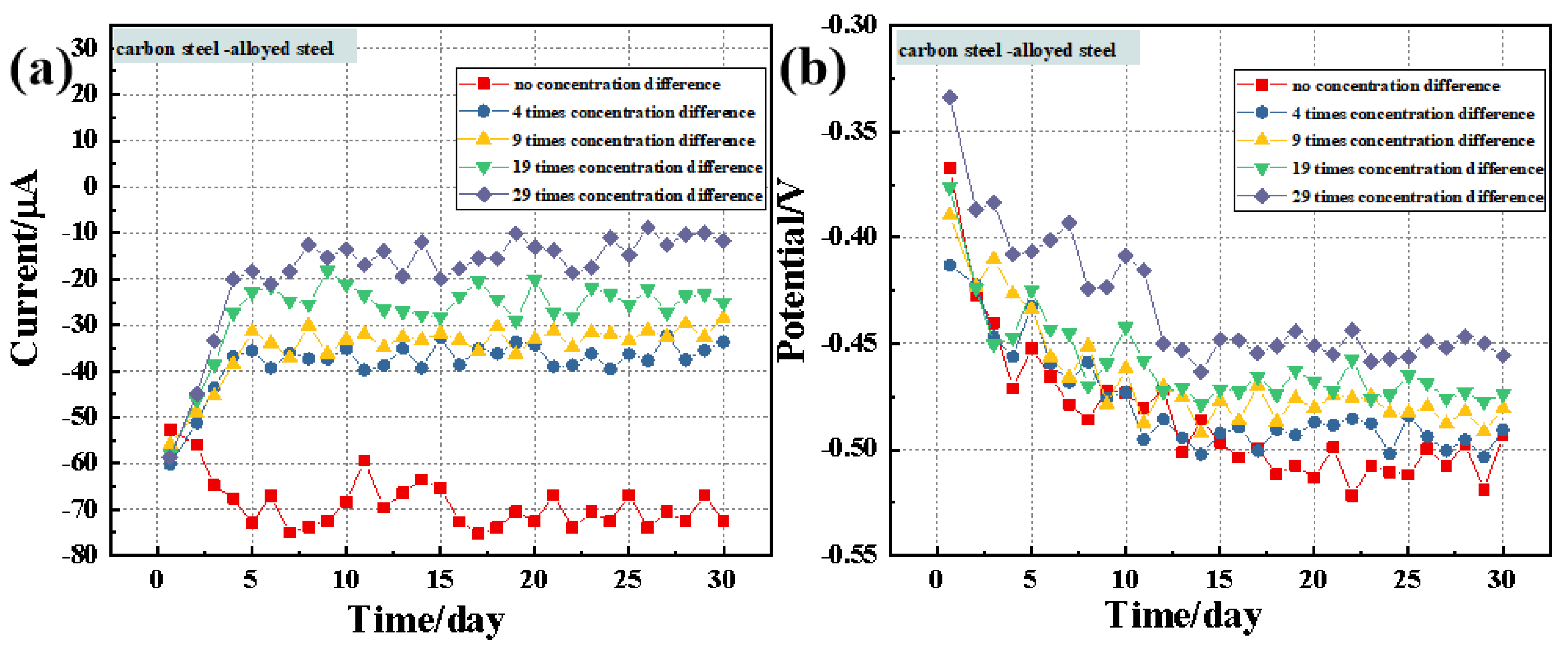
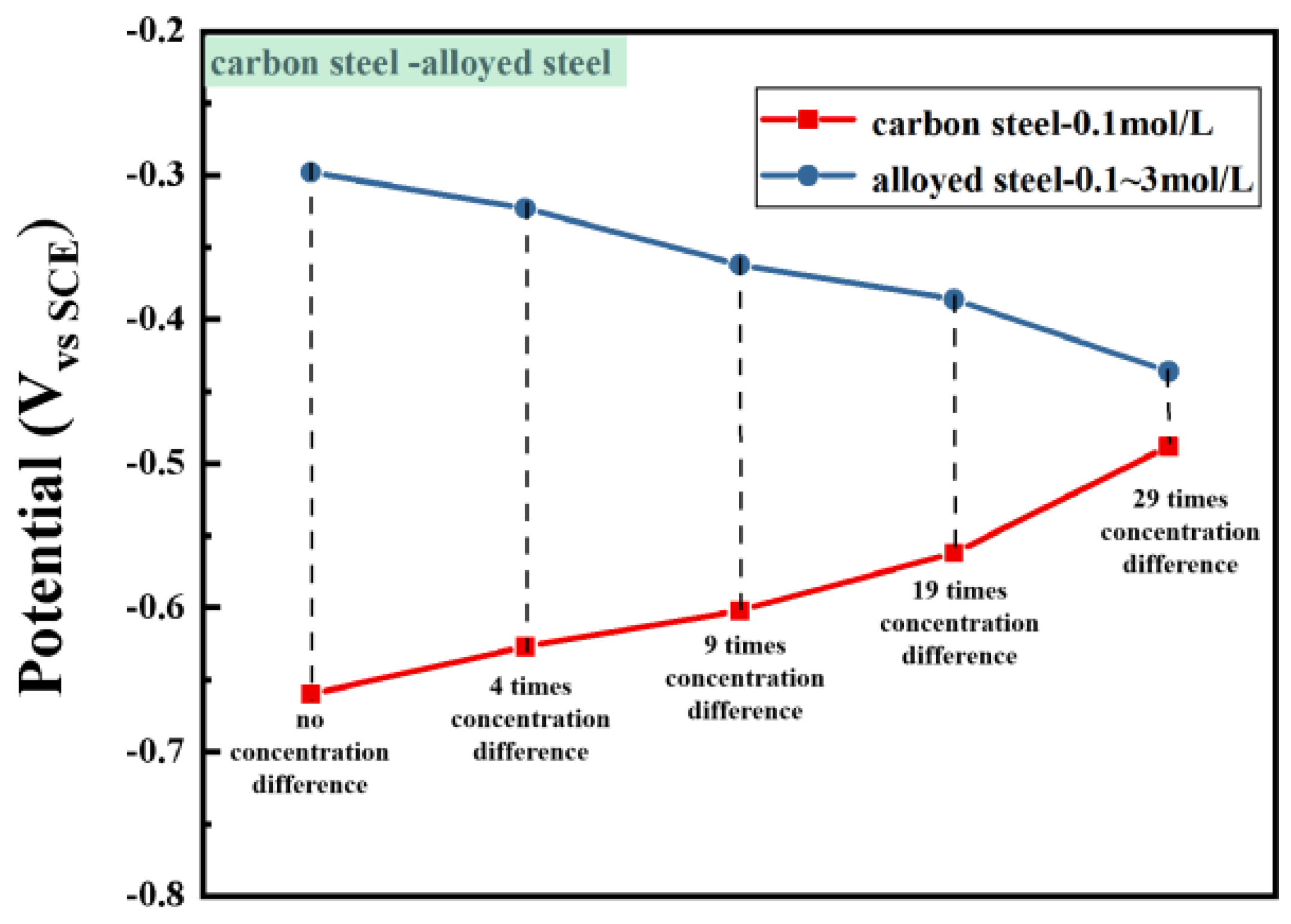
3.2. Macro-Cell Corrosion Induced by the Chloride Ion Concentration Difference in Dissimilar Steel Based on the ZRA Testing

Experimental conditions for macro-cell corrosion induced by a chloride ion concentration difference in dissimilar steel were created by setting two chloride ion concentration difference conditions in the simulated concrete solution. Figure 4 depicts a schematic diagram of the experimental setup for inducing macro-cell corrosion in dissimilar steel (carbon steel–alloyed steel combination) in a simulated concrete solution with varying chloride ion concentration difference conditions, along with the wiring method for the ZRA testing. More corrosion-resistant alloyed steel is placed in the simulated concrete solution with a high chloride ion concentration area and designated as the corrosion anode [31], while less corrosion-resistant carbon steel is placed in the low-concentration area and designated as the corrosion cathode. Five different chloride ion concentration difference conditions are set in the simulated concrete solution: no concentration difference, 4 times concentration difference, 9 times concentration difference, 19 times concentration difference, and 29 times concentration difference. The ZRA four-electrode method is similarly used to test the macro-cell corrosion current and coupling potential.
As shown in Figure 5a, the macro-cell corrosion current values for the dissimilar steel combination (carbon steel–alloyed steel) are all negative, indicating that the assumed cathode–anode polarity is the opposite of the actual situation. Therefore, the carbon steel in the low chloride ion concentration area should be considered as the corrosion anode, while the alloyed steel in the high chloride ion concentration area should be considered as the cathode. This phenomenon is likely attributed to a higher corrosion resistance of the alloyed steel. Due to the significantly higher basic corrosion resistance of the alloyed steel compared with the carbon steel, the former may still exhibit a higher potential in high chloride salt concentrations than the latter, leading to the actual reversal of the cathode–anode polarity in the macro-cell corrosion system of dissimilar steel. In terms of the overall evolution pattern of the macro-cell corrosion current, except under conditions with no chloride ion concentration difference, the macro-cell corrosion current for the dissimilar steel decreases significantly from 1 to 5 days and gradually stabilizes thereafter [32]. Additionally, the steady-state value of the macro-cell corrosion current decreases gradually with an increase in the chloride ion concentration difference. When reaching a 29 times concentration difference, the macro-cell corrosion current for dissimilar steel decreases to around −10 μA, approximately one-tenth of that for the carbon steel combination under the same concentration difference, which is equivalent to that for the alloyed steel combination under the same concentration difference condition. Under conditions with no concentration difference, the macro-cell corrosion current for dissimilar steel gradually increases before slowing down and stabilizing at around −70 μA. From the time-varying curve of the coupling potential in Figure 5b, it can be observed that a range of variation in coupling potential for dissimilar steel is within −450 to −500 mV, gradually decreasing with an increase in the chloride ion concentration difference, indicating that the driving force for the macro-cell corrosion of dissimilar steel weakens with the increase in the chloride ion concentration difference.

3.3. Evaluation of Corrosion Resistance after the Macro-Cell Corrosion Induced by the Chloride Ion Concentration Difference in the Same Steel

Figure 6 presents the electrochemical performance evaluation test conducted after 15 days of chloride ion-induced macro-cell corrosion of the same type of steel. Tests employed a three-electrode test system to evaluate the electrochemical performance of the steel on both sides using electrochemical impedance spectroscopy (EIS) and potentiodynamic polarization (PDP) techniques. During the test, the reference electrode and counter electrode were simultaneously placed in the solution on one side of the test steel specimen to avoid testing errors caused by a concentration difference.

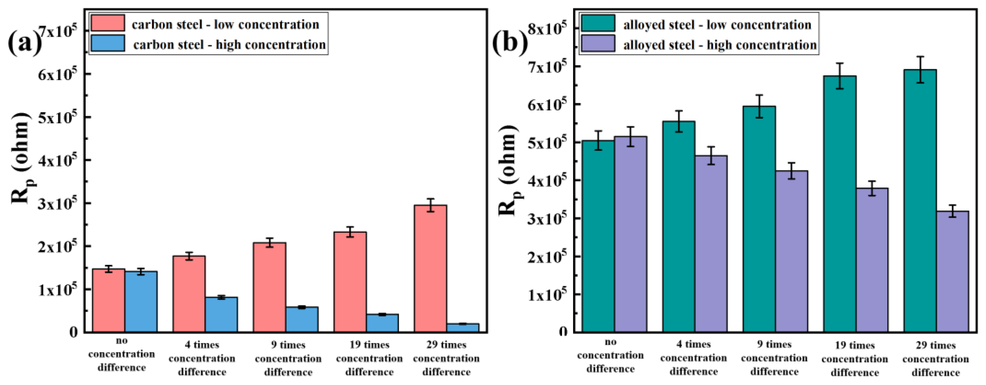
3.3.1. Electrochemical Impedance Spectroscopy Testing after Macro-Cell Corrosion

Figure 7 shows the electrochemical impedance spectroscopy (EIS) plots of carbon steel macro-cell corrosion in a simulated concrete solution under different chloride ion concentration difference conditions after 15 days. Panels (a), (b), and (c) depict the Nyquist plots, Bode phase angle plots, and Bode impedance modulus plots for carbon steel samples in the low-concentration area, while panels (d), (e), and (f) depict the same for samples in the high-concentration area. The change in the Nyquist spectra reveals that the capacitive arc radius of carbon steel in the low-concentration area gradually increases with a rise in the chloride ion concentration difference, while that of carbon steel in the high-concentration area decreases with increasing the chloride ion concentration difference, indicating exacerbated macro-cell corrosion damage and deteriorating corrosion resistance.
From the phase angle plots, it can be observed that the maximum phase angle of carbon steel in the low-concentration area ranges between 60° and 50°, with both phase angle values and peak width increasing with a rise in the chloride ion concentration difference. Conversely, for carbon steel in the high-concentration area, the maximum phase angle ranges between 40° and 50°, with both the phase angle values and peak width decreasing with the increasing chloride ion concentration difference. The magnitude of the maximum phase angle reflects the surface smoothness of the sample to some extent, indicating the extent of corrosion damage [33]. Overall, the maximum phase angle of both sides of the carbon steel is relatively small, suggesting significant damage to the passive film on the surface of the steel. In comparison, the carbon steel in the low-concentration area exhibits higher phase angle values, indicating less corrosion damage, which remains relatively stable with the increasing chloride ion concentration difference, while the opposite trend is observed for carbon steel in the high-concentration area. In conclusion, with the increase in chloride ion concentration difference, the carbon steel in the high-concentration area accelerates corrosion as the anode in the macro-cell corrosion system, while the carbon steel in the low-concentration area, acting as the cathode, receives some protection. However, due to the poor corrosion resistance of carbon steel itself, the cathodic carbon steel in the macro-cell corrosion system still suffers from significant corrosion.
Figure 8 depicts the electrochemical impedance spectroscopy (EIS) plots of alloyed steel macro-cell corrosion in simulated concrete solutions under different chloride ion concentration difference conditions after 15 days. Panels (a), (b), and (c) show the Nyquist plots, Bode phase angle plots, and Bode impedance modulus plots for alloyed steel in the low-concentration area, while panels (d), (e), and (f) show the same for samples in the high-concentration area. The Nyquist plot reveals that the impedance arc of alloyed steel in the low-concentration area gradually increases with a rise in the chloride ion concentration difference. Additionally, from the Bode phase angle plot, it is evident that the highest phase angle of the alloyed steel in the low-concentration area also increases, and the peak width gradually widens [34]. At 29 times concentration difference, the maximum phase angle exceeds 80°. Thus, it can be inferred that the cathodic alloyed steel in the low-concentration area is protected by the macro-cell corrosion current. The phase angle of all five sample sets is above 70°, indicating high surface smoothness and minimal surface corrosion damage. The evolution of the impedance modulus exhibits the same trend as observed in the Nyquist and Bode plots.
For alloyed steel in the high-concentration region, its Nyquist impedance arc gradually decreases with an increase in the chloride ion concentration difference, and the upward trend also gradually declines [35]. The highest phase angle in the Bode plot also decreases, from over 80° in no concentration difference to around 58°. The impedance modulus plot also shows a similar trend. Thus, it can be inferred that macro-cell corrosion occurs in the alloyed steel in the simulated concrete solution induced by the chloride ion concentration difference, and the alloyed steel in the high-concentration area acts as the anode of the macro-cell corrosion system and undergoes accelerated corrosion.
We conducted linear fitting of the electrochemical impedance spectroscopy (EIS) using ZSimpWin3.5 software and equivalent circuits such as Rs(RctQdl)(RfQf). Figure 9 shows the bar chart of Rp values for carbon steel and alloyed steel combinations on the high- and low-concentration sides under different chloride ion concentration difference conditions. From Figure 9, it can be observed that the changing trend of polarization resistance (Rp) for both carbon steel and alloyed steel samples corresponds to the electrochemical impedance spectroscopy. Specifically, under the 29 times concentration difference condition on both sides, the polarization resistance of alloyed steel on the low-concentration side is twice that on the high-concentration side, while for the carbon steel combination, the polarization resistance on the low-concentration side is more than ten times that on the high-concentration side. This indicates that under macro-cell corrosion induced by the chloride ion concentration difference, the difference in electrochemical reaction resistance between the two sides of alloyed steel is smaller, and the surface condition of the steel on both sides is closer after macro-cell corrosion induced by the chloride ion concentration difference [36].

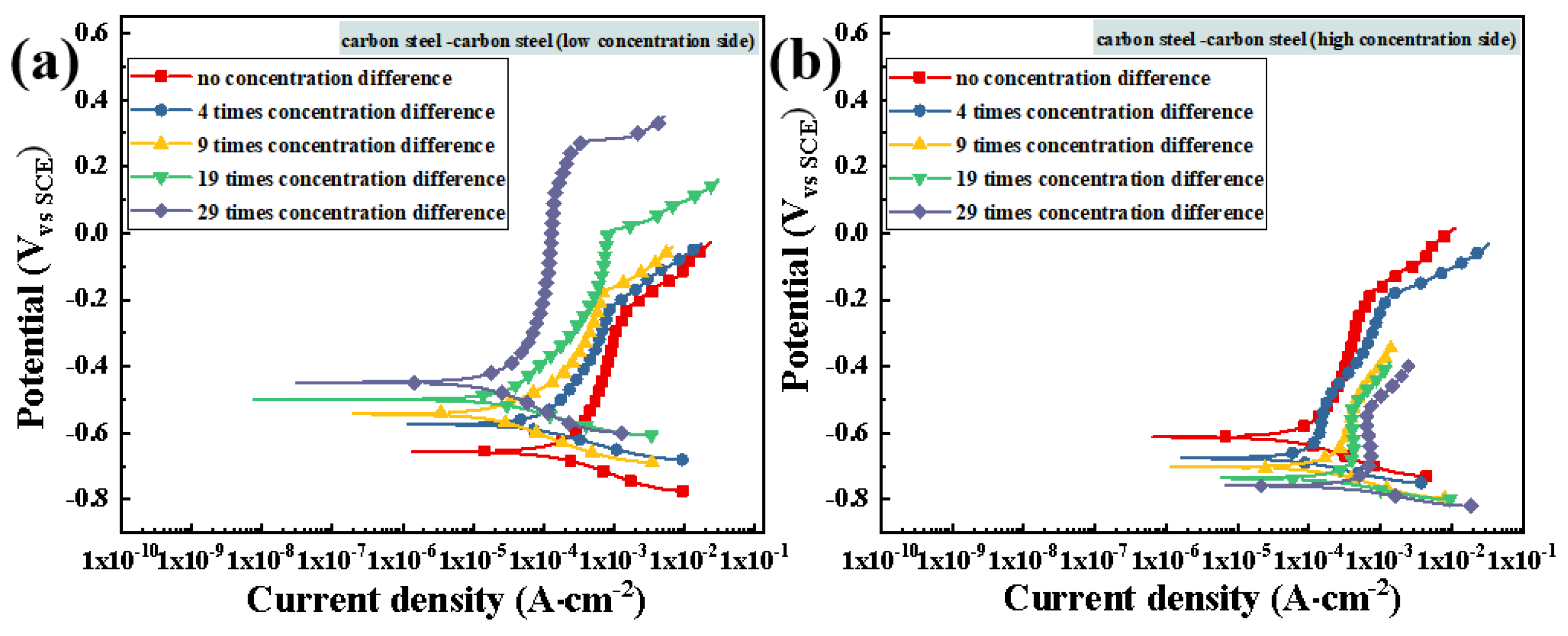
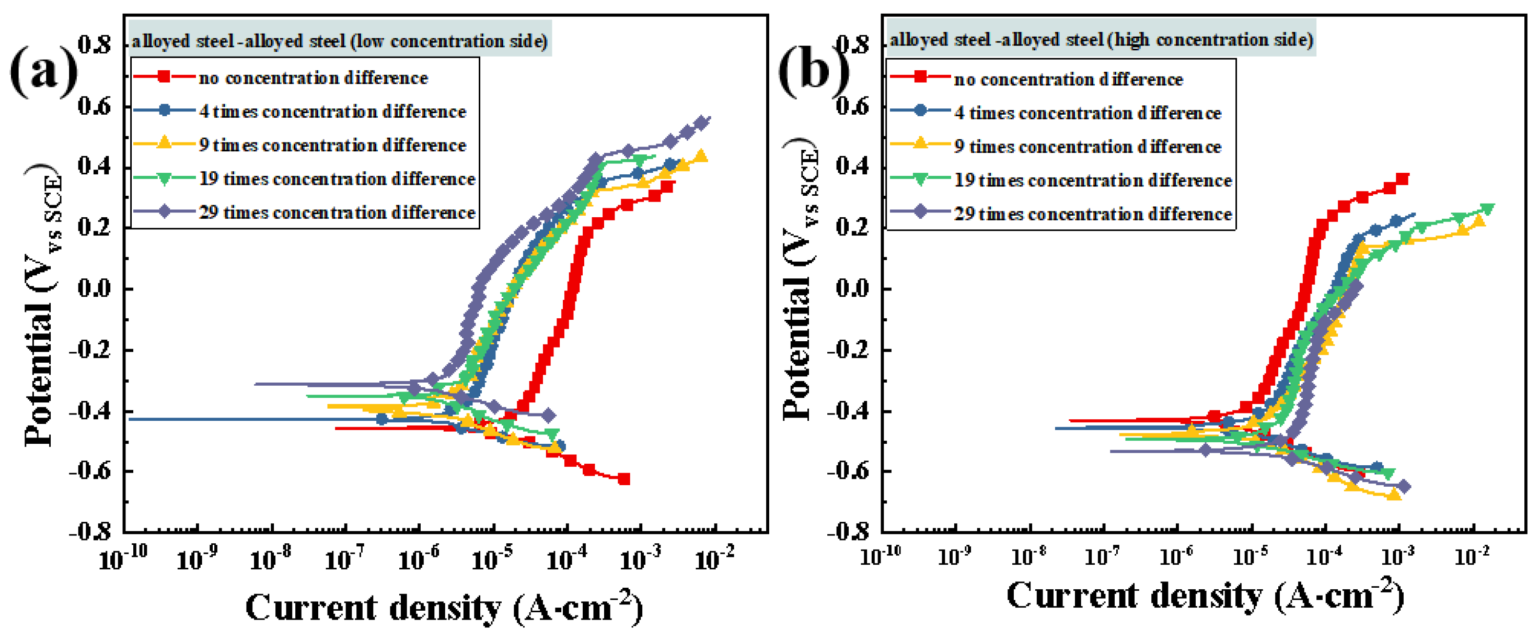
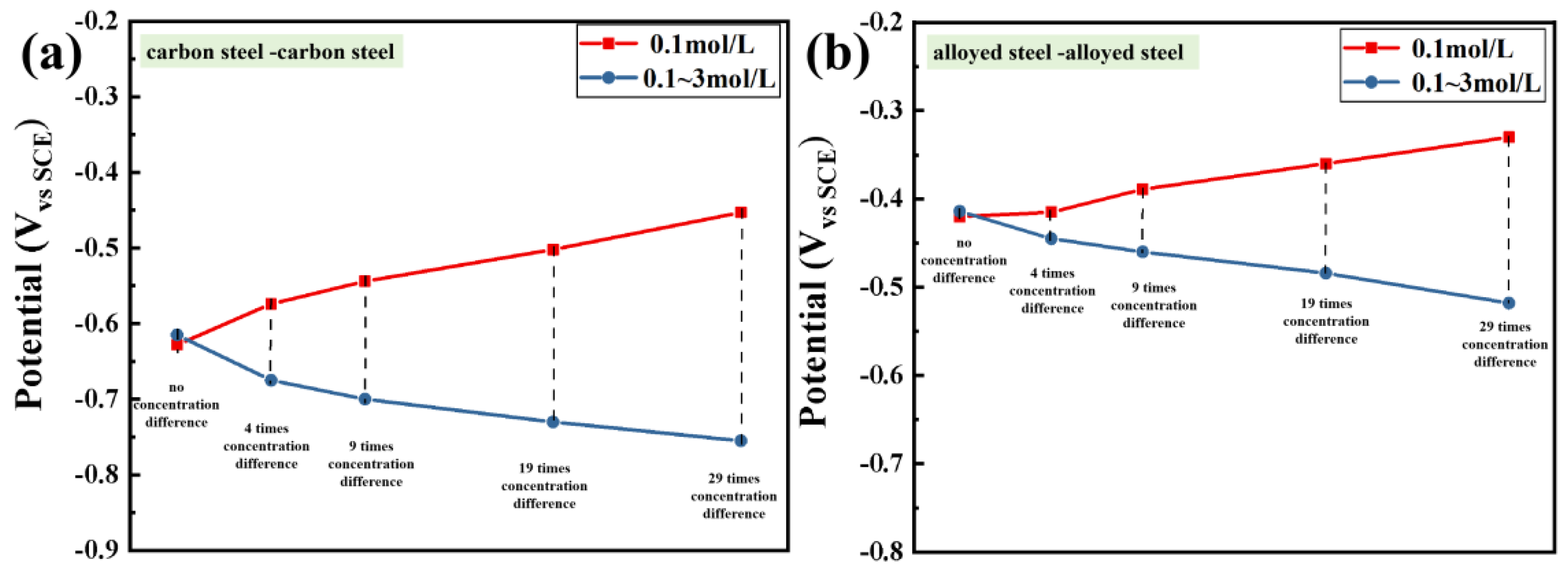
3.3.2. Potentiodynamic Polarization Testing after Macro-Cell Corrosion

Figure 10 depicts the potentiodynamic scanning polarization curves of carbon steel combinations in simulated concrete solutions induced by different chloride ion concentrations after 15 days of macro-cell corrosion. As shown in Figure 10a, it can be observed that the open-circuit potential Ecorr of carbon steel at low concentrations gradually shifts positively with the increasing chloride ion concentration difference, while the corrosion current density Icorr gradually decreases. The details are provided in Table 2. Additionally, the passivation range of the anodic polarization curve for carbon steel at low concentrations expands with the increasing chloride ion concentration difference, and the pitting potential also increases. In contrast, in the potentiodynamic polarization curves of carbon steel in the high-concentration area (as shown in Figure 10b), Ecorr gradually shifts negatively with the increasing chloride ion concentration difference, while Icorr gradually increases. When the chloride ion concentration difference increases to 29 times, the self-corrosion current density of carbon steel in the high-concentration area increases by about 3 times compared with that without concentration, indicating a significant increase in the corrosion rate [37]. Moreover, the passivation range of the anodic polarization curve also decreases with the increasing chloride ion concentration difference, and the pitting potential decreases accordingly.
Figure 11 shows the potentiodynamic scanning polarization curves of alloyed steel combinations in simulated concrete solutions induced by different chloride ion concentrations after 15 days of macro-cell corrosion. The polarization curve of alloyed steel at low concentrations is shown in Figure 11a where the overall Ecorr of alloyed steel at low concentrations is relatively high and gradually shifts positively with the increasing chloride ion concentration difference, accompanied by a gradual decrease in Icorr, as detailed in Table 3. Furthermore, the pitting potential of alloyed steel at low concentrations increases, while the change in the passivation range of the anodic polarization is not significant. The polarization curve of alloyed steel in the high-concentration area is shown in Figure 11b where Ecorr is significantly lower than that of alloyed steel at low concentrations and it decreases with the increasing chloride ion concentration, while Icorr increases accordingly. When the chloride ion concentration difference rises to 29 times, Icorr increases by about 53% compared with that without a concentration difference.
Combining the EIS and PDP test data, it can be concluded that both carbon steel combinations and alloyed steel combinations in simulated concrete solution have experienced varying degrees of macro-cell corrosion induced by the chloride ion concentration difference, and the corrosion severity increases with the increase in the chloride ion concentration. In the aforementioned macro-cell corrosion system, the low-concentration steel acts as the cathode and receives a certain degree of protection, while the high-concentration steel acts as the anode and undergoes accelerated corrosion. Comparatively, the corrosion resistance of alloyed steel is better, and under the same chloride ion concentration, the corrosion damage induced by macro-cell corrosion is significantly reduced compared with carbon steel.
It is generally believed that the potential difference between the anode and cathode in the macro-cell corrosion system becomes the driving force for macro-cell corrosion, with a greater potential difference resulting in stronger macro-cell corrosion driving force. Figure 12a,b respectively shows the evolution of the self-corrosion potential of carbon steel combinations and alloyed steel combinations under different chloride ion concentrations. It is evident that with a gradual increase in the chloride ion concentration difference, the potential difference between the cathode and anode for both types of steel gradually increases, leading to a strengthening of the driving force for macro-cell corrosion, exhibiting similar developmental trends. When the chloride ion concentration difference reaches 29 times, the potential difference between the anode and cathode of carbon steel reaches 297 mV, providing a significant driving force for macro-cell corrosion. However, the potential difference between the anode and cathode of the alloyed steel combination is significantly smaller than that of the carbon steel combination throughout the process, with a potential difference of only 158 mV at 29 times chloride ion concentration difference, indicating a significant weakening of the driving force for macro-cell corrosion compared with carbon steel.

3.4. Evaluation of Corrosion Resistance after Macro-Cell Corrosion Induced by the Chloride Ion Concentration Difference in Dissimilar Steel

Figure 13 illustrates the electrochemical performance evaluation test conducted on carbon steel in the low-concentration region and alloyed steel in the high-concentration region.

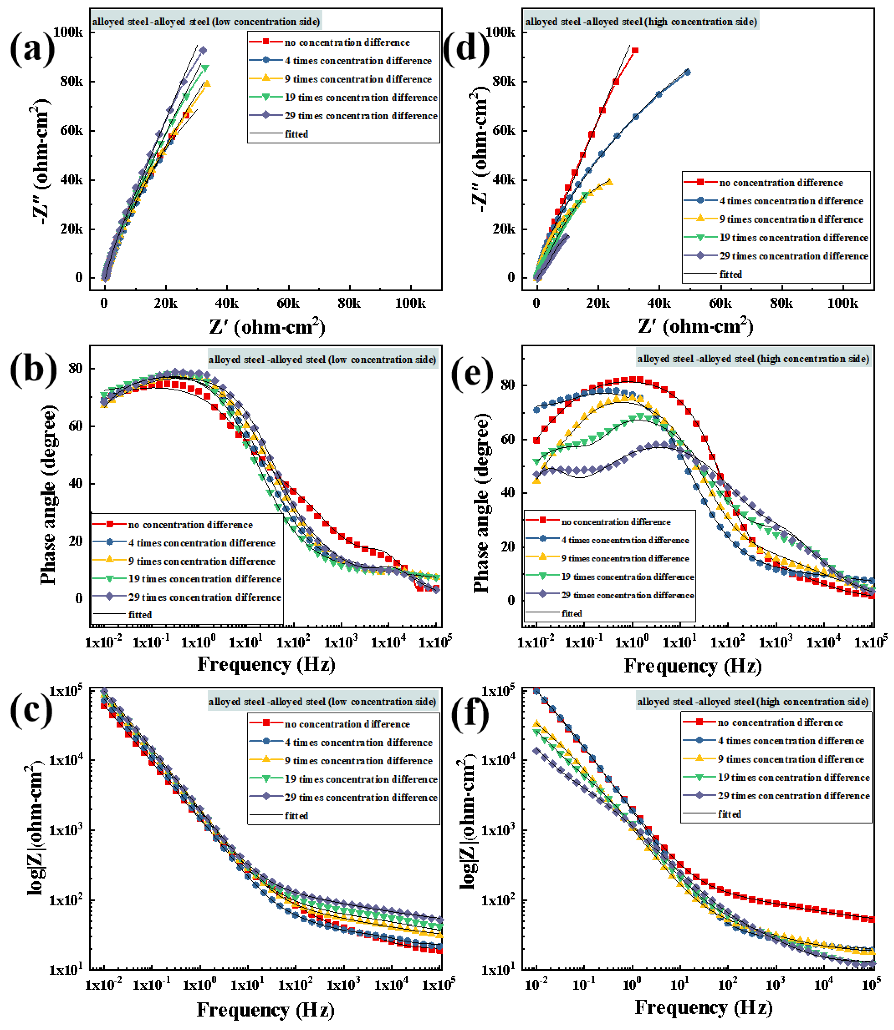
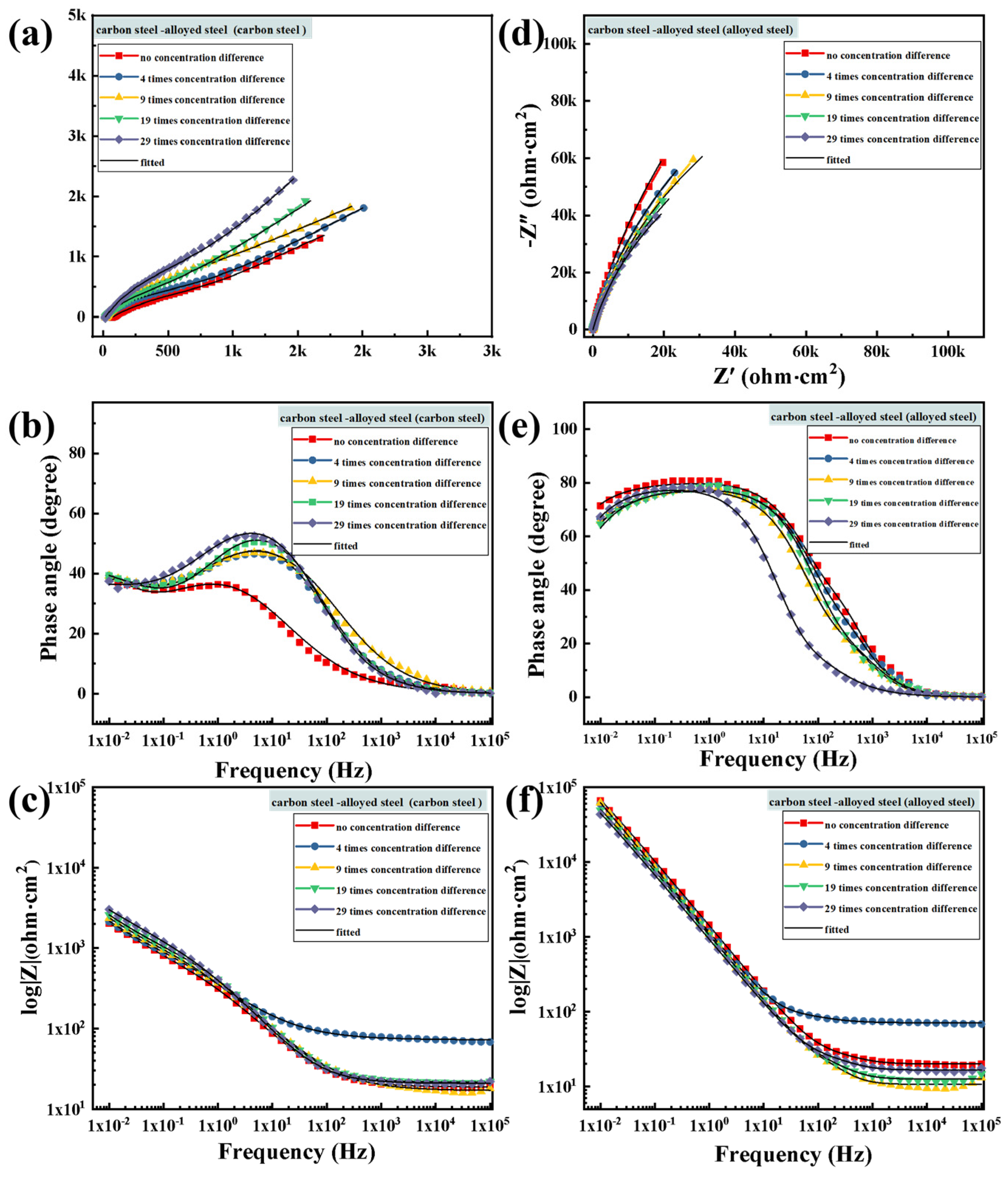
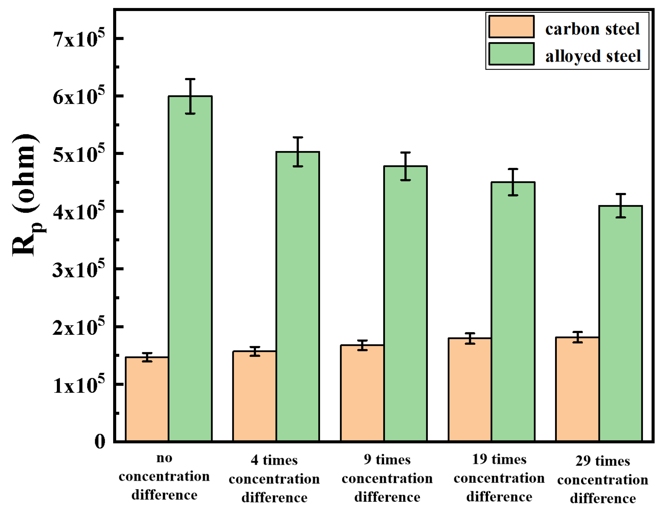
3.4.1. Electrochemical Impedance Spectroscopy Testing after Macro-Cell Corrosion

Figure 14 shows the electrochemical impedance spectroscopy (EIS) results after 30 days of macro-cell corrosion of carbon steel–alloyed steel combination under five different concentration difference conditions. First, from the Nyquist plot of carbon steel at 0.1 mol/L chloride ion concentration (Figure 14a), it can be observed that the impedance arc radius increases significantly with the increase in concentration multiples, indicating enhanced corrosion resistance of carbon steel in the low-concentration area. The change in the phase angle curve in the Bode plot of carbon steel (Figure 14b) indicates that the maximum phase angle and peak width increase with an increase in the chloride ion concentration difference on both sides [38]. When the chloride ion concentration difference on both sides reaches 29 times, the maximum phase angle differs by nearly 20° compared with that without concentration difference, suggesting that the increase in the chloride ion concentration difference on both sides provides effective protection to the surface of carbon steel. The impedance modulus plot (Figure 14c) also shows an increase in impedance modulus with an increase in the concentration difference.
Furthermore, from the Nyquist plot of alloyed steel in the high-concentration area (Figure 14d), it can be seen that the impedance arc radius gradually decreases with an increase in the chloride ion concentration on both sides of the solution. However, the curves of the five sample sets fluctuate slightly, indicating no significant differences due to high-concentration multiples. This suggests that after macro-cell corrosion of both galvanic corrosion and concentration corrosion, the alloyed steel in the high-concentration area still exhibits good corrosion resistance. In the phase angle plot (Figure 14e), it can be observed that the maximum phase angle and peak width of alloyed steel under different concentration conditions decrease with an increase in the chloride ion concentration difference, but the maximum phase angle remains around 80°, indicating that there is little difference in surface smoothness of the alloyed steel and it remains relatively high. It can be inferred that the surface corrosion situation is relatively mild, which corresponds to the observation of macroscopic morphology. Similarly, the impedance modulus plot (Figure 14f) shows the same change trend, indicating that the alloyed steel still has strong corrosion resistance even after macro-cell corrosion induced by the high-concentration difference [39]. The macro-cell corrosion induced by the chloride ion concentration difference does not significantly reduce its corrosion resistance.
Figure 15 shows the bar chart of Rp values for carbon steel–alloyed steel combinations on the high- and low-concentration sides under different chloride ion concentration difference conditions. It can be observed that the variation trend of polarization resistance in each group of specimens aligns with the pattern observed in the electrochemical impedance spectroscopy. Compared with the carbon steel group, the difference in polarization resistance between the carbon steel and alloyed steel on both sides of the combination does not exhibit a significant disparity due to galvanic corrosion [40]. Moreover, the corrosion states between the carbon steel and alloyed steel specimens gradually converge as the chloride ion concentration difference increases.

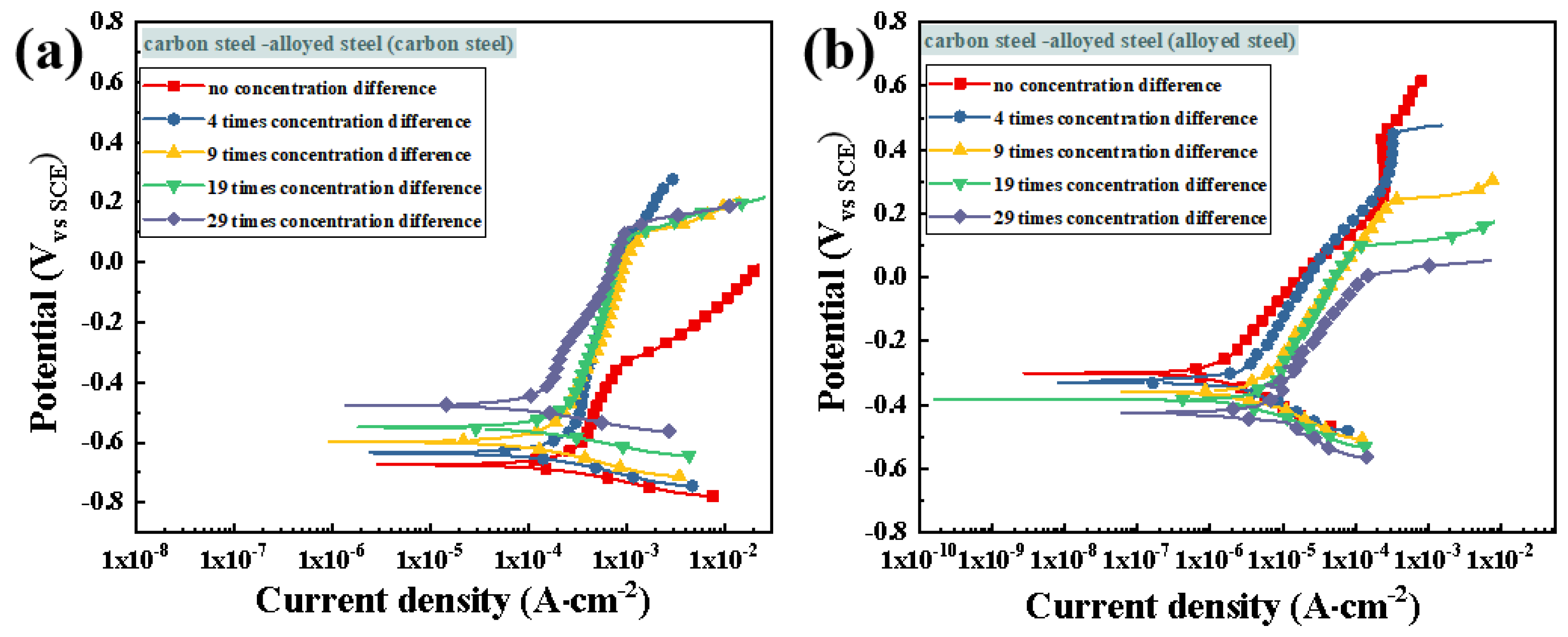
3.4.2. Potentiodynamic Polarization Testing after Macro-Cell Corrosion

Figure 16 presents the potentiodynamic scanning polarization curves of carbon steel–alloyed steel combinations after 30 days of macro-cell corrosion induced by different chloride ion concentration difference conditions. Figure 16a shows the potentiometric polarization curve of carbon steel in the 0.1 mol/L low chloride ion concentration area. The change trends of the curves under different chloride ion concentration difference conditions indicate that as the chloride ion concentration difference increases, Ecorr gradually shifts positively and Icorr also shows a decreasing trend, as detailed in Table 4. Additionally, the pitting potential increases significantly with an increase in the chloride ion concentration difference. Figure 16b shows the polarization curves of alloyed steel in the high-concentration area under different chloride ion concentration conditions. Overall, the Ecorr of alloyed steel is higher than that of carbon steel, and the differences in Ecorr and Icorr among the specimens are relatively small. According to Table 4, with an increase in the concentration difference, the Ecorr of alloyed steel gradually decreases, and Icorr also gradually increases, but without significant differences, while the pitting potential decreases noticeably.
Combining the EIS and PDP test data, when carbon steel-alloyed steel is combined in a simulated concrete solution under concentration difference macro-cell corrosion conditions, the corrosion degree of carbon steel decreases with an increase in the chloride ion concentration difference, while the anodic alloyed steel still exhibits good corrosion resistance in high chloride ion concentration environments. Compared with combinations of the same type of steel, the higher the chloride ion concentration, the more pronounced the inhibitory effect on macro-cell corrosion for carbon steel–alloyed steel combinations.
Figure 17 shows the difference in the self-corrosion potential of carbon steel–alloyed steel combination with the change in the chloride ion concentration difference on both sides of the solution. Obviously, the self-corrosion potential difference between the two types of steel gradually narrows with an increase in the chloride ion concentration difference. With the expansion of concentration difference [41], the self-corrosion potential difference decreases to 54 mV at 29 times concentration difference, reducing the corrosion driving force by approximately 85%, which is only about 1/6 of the corrosion driving force of carbon steel combination at 29 times concentration difference, indicating a significant decrease in the corrosion driving force of the carbon steel–alloyed steel combination with an increase in the chloride ion concentration difference.

4. Conclusions

In this paper, the macro-cell corrosion behavior and corrosion resistance of alloyed steel and carbon steel covered with a concrete protective layer in the marine chloride ion erosion environment are studied. By systematically studying the macro-cell corrosion behavior induced by the chloride ion concentration difference in simulated concrete solution for the same and dissimilar steel, the corrosion morphology of the steel after 15 days of macro-cell corrosion was observed, and the electrochemical properties and corrosion resistance of the steel were evaluated. The preliminary findings revealed the influence of the chloride ion concentration difference on the macro-cell corrosion of alloyed steel. The conclusions are as follows:
(1) In the macro-cell corrosion system induced by the chloride ion concentration difference in the simulated concrete solution, the steel in the low-concentration region acts as the cathode, while the steel in the high-concentration region acts as the anode. With an increase in the chloride ion concentration difference, the potential difference between the anode and cathode steels increases, enhancing the driving force of macro-cell corrosion. As a result, the macro-cell corrosion current of both carbon steel combinations and alloyed steel combinations increases, leading to accelerated macro-cell corrosion. Under the same concentration difference, macro-cell corrosion is milder in the alloyed steel combination, with the corrosion current of the alloyed steel combination at 29 times the concentration difference being only 1/10 of that of the carbon steel combination.
(2) In the macro-cell corrosion system induced by the chloride ion concentration difference in the simulated concrete solution involving dissimilar steels, due to the superior corrosion resistance of alloyed steel compared with carbon steel, the carbon steel in the low-concentration region acts as the anode, while the alloyed steel in the high-concentration region acts as the cathode. With an increase in the chloride ion concentration difference, the potential difference between the cathodic and anodic steel decreases, weakening the driving force for macro-cell corrosion and inhibiting macro-cell corrosion of dissimilar steel combinations. At 29 times concentration difference, the potential difference of the dissimilar steels in the macro-cell corrosion is only 1/6 of that of the carbon steel combination at the same concentration difference, and the corrosion current is only 1/10 of that of the carbon steel combination.
Through the combination of carbon steel and alloyed steel, the advantages of both can be fully utilized, which not only ensures the high strength and hardness of the steel pipe rod but also significantly improves its anti-corrosion performance. It can better adapt to the corrosion challenges of offshore environments, prolong its service life, reduce maintenance costs, and ensure the safe operation of transmission lines.

Author Contributions

Conceptualization, F.L., S.Z., G.Z., G.W., X.W., X.Q., J.X. and D.S.; formal analysis, F.L., X.Z., Z.D., G.W. and X.W.; investigation, F.L., X.Z. and D.S.; resources, F.L. and X.Z.; writing—original draft, X.Z., Z.D., S.Z. and G.Z.; writing—review and editing, X.Z., Z.D., S.Z., and G.Z.; visualization, Z.D., S.Z. and G.Z.; supervision, F.L. and D.S.; project administration, D.S.; funding acquisition, F.L., X.Z., Z.D., G.W., X.W. and D.S. All authors have read and agreed to the published version of the manuscript.

Funding

This research was funded by the State Grid Jiangsu Electric Power Co., Ltd. Technology Project, grant number J2023009.

Institutional Review Board Statement

Not applicable.

Informed Consent Statement

Not applicable.

Data Availability Statement

The raw data supporting the conclusions of this article will be made available by the authors on request.

Conflicts of Interest

Author Feng Lyu, Xinyue Zhou, Zheng Ding were employed by the State Grid Wuxi Power Supply Company. The remaining authors declare that the research was conducted in the absence of any commercial or financial relationships that could be construed as a potential conflict of interest.

References

  1. Zhou, H.; Chen, S.; Zhou, Y.; Lin, Z.; Liang, X.; Liu, J.; Xing, F. Field test of a reinforced concrete bridge under marine environmental corrosion. Eng. Fail. Anal. 2020, 115, 104669. [Google Scholar] [CrossRef]
  2. Ou, Y.C.; Fan, H.D.; Nguyen, N.D. Long-term seismic performance of reinforced concrete bridges under steel reinforcement corrosion due to chloride attack. Earthq. Eng. Struct. Dyn. 2013, 42, 2113–2127. [Google Scholar] [CrossRef]
  3. Han, X.; Yang, D.Y.; Frangopol, D.M. Optimum maintenance of deteriorated steel bridges using corrosion resistant steel based on system reliability and life-cycle cost. Eng. Struct. 2021, 243, 112633. [Google Scholar] [CrossRef]
  4. Natkunarajah, K.; Masilamani, K.; Maheswaran, S.; Lothenbach, B.; Amarasinghe, D.; Attygalle, D. Analysis of the trend of pH changes of concrete pore solution during the hydration by various analytical methods. Cem. Concr. Res. 2022, 156, 106780. [Google Scholar] [CrossRef]
  5. Grengg, C.; Müller, B.; Staudinger, C.; Mittermayr, F.; Breininger, J.; Ungerböck, B.; Borisov, S.M.; Mayr, T.; Dietzel, M. High-resolution optical pH imaging of concrete exposed to chemically corrosive environments. Cem. Concr. Res. 2019, 116, 231–237. [Google Scholar] [CrossRef]
  6. Feng, Y.C.; Yang, J.B.; Zhang, P. Effects of carbonation curing regimes on alkalinity of self-compacting concretes for marine artificial reef. Constr. Build. Mater. 2023, 369, 130614. [Google Scholar] [CrossRef]
  7. Hansson, C.M.; Poursaee, A.; Laurent, A. Macrocell and microcell corrosion of steel in ordinary Portland cement and high performance concretes. Cem. Concr. Res. 2006, 36, 2098–2102. [Google Scholar] [CrossRef]
  8. Jin, Z.-H.; Jiang, C.; Gu, X.-L.; Dong, Z. Macro-cell corrosion between crossed steel bars in cracked concrete. Constr. Build. Mater. 2022, 350, 128867. [Google Scholar] [CrossRef]
  9. Wang, D.; Zhong, Q.; Yang, J.; Zhang, S. Effects of Cr and Ni on the microstructure and corrosion resistance of high-strength low alloy steel. J. Mater. Res. Technol. 2023, 23, 36–52. [Google Scholar] [CrossRef]
  10. Blikharskyy, Y.; Selejdak, J.; Kopiika, N. Corrosion Fatigue. Corrosion Fatigue Damages of Rebars under Loading in Time. Materials 2021, 14, 3416. [Google Scholar] [CrossRef]
  11. Mohtadi-Bonab, M.A. Effects of Different Parameters on Initiation and Propagation of Stress Corrosion Cracks in Pipeline Steels: A Review. Metals 2019, 9, 590. [Google Scholar] [CrossRef]
  12. Tsouli, S.; Lekatou, A.G.; Nikolaidis, C.; Kleftakis, S. Corrosion and tensile behavior of 316L stainless steel concrete reinforcement in harsh environments containing a corrosion inhibitor. Procedia Struct. Integr. 2019, 17, 268–275. [Google Scholar] [CrossRef]
  13. Martin, U.; Ress, J.; Bosch, J.; Bastidas, D. Stress corrosion cracking mechanism of AISI 316LN stainless steel rebars in chloride contaminated concrete pore solution using the slow strain rate technique. Electrochim. Acta 2020, 335, 135565. [Google Scholar] [CrossRef]
  14. Abreu, C.; Cristóbal, M.; Montemor, M.; Nóvoa, X.; Pena, G.; Pérez, M. Galvanic coupling between carbon steel and austenitic stainless steel in alkaline media. Electrochim. Acta 2002, 47, 2271–2279. [Google Scholar] [CrossRef]
  15. Karla, H.; Ueli, M.A.; Bernhard, E.; Larsen, C.K.; Geiker, M.R. Influence of mortar resistivity on the rate-limiting step of chloride-induced macro-cell corrosion of reinforcing steel. Corros. Sci. 2016, 110, 46–56. [Google Scholar]
  16. Li, X.; Shu, J.; Chen, L.; Bi, H. Effect of Cerium on High-Temperature Oxidation Resistance of 00Cr17NbTi Ferritic Stainless Steel. Acta Metall. Sin. (Engl. Lett.) 2014, 27, 501–507. [Google Scholar] [CrossRef]
  17. Rabi, M.; Cashell, K.; Shamass, R.; Desnerck, P. Bond behaviour of austenitic stainless steel reinforced concrete. Eng. Struct. 2020, 221, 111027. [Google Scholar] [CrossRef]
  18. Liu, Q.; Liu, Z.; Guo, S.; Xiao, Y. Study on galvanic corrosion behavior of 5083 aluminum alloy and 30CrMnSiA steel in different Cl- concentrations. J. Chin. Soc. Corros. Protect. 2021, 41, 883–891. [Google Scholar]
  19. Hao, L.; Li, N.; Li, D. Galvanic Corrosion Behavior of Hastelloy C-276 Alloy and 16MnR Steel in Hydrochloric Acid. Mater. Prot. 2011, 44, 49–51+8. [Google Scholar]
  20. Peng, Z.; Wu, J.; Wang, C. Effect of Temperature on Galvanic Corrosion Behavior of Industrial Pure Titanium and Low Alloy Steel. Corros. Sci. Prot. Technol. 2013, 25, 463–469. [Google Scholar]
  21. Wang, P.; Cai, J.; Cheng, X.; Ma, L.; Li, X. Inhibition of galvanic corrosion between crystallographic orientations in low alloy steel by grain ultra-refinement. Mater. Today Commun. 2022, 31, 103742. [Google Scholar] [CrossRef]
  22. Okonkwo, B.O.; Ming, H.; Wang, J.; Han, E.-H.; Rahimi, E.; Davoodi, A.; Hosseinpour, S. A new method to determine the synergistic effects of area ratio and microstructure on the galvanic corrosion of LAS A508/309 L/308 L SS dissimilar metals weld. J. Mater. Sci. Technol. 2021, 78, 38–50. [Google Scholar] [CrossRef]
  23. Zhang, B.; Liu, W.; Sun, Y.; Yang, W.; Chen, L.; Xie, J.; Li, W. Corrosion behavior of the 3 wt.% Ni weathering steel with replacing 1 wt.% Cr in the simulated tropical marine atmospheric environment. J. Phys. Chem. Solids 2023, 175, 111221. [Google Scholar] [CrossRef]
  24. Yang, B.; Shi, C.; Teng, J.; Gong, X.; Ye, X.; Li, Y.; Lei, Q.; Nie, Y. Corrosion behaviours of low Mo Ni-(Co)-Cr-Mo alloys with various contents of Co in HF acid solution. J. Alloys Compd. 2019, 791, 2125–2224. [Google Scholar] [CrossRef]
  25. Vedalakshmi, R.; Kumar, K.; Raju, V.; Rengaswamy, N. Effect of prior damage on the performance of cement based coatings on rebar: Macrocell corrosion studies. Cem. Concr. Compos. 2000, 22, 417–421. [Google Scholar] [CrossRef]
  26. Zou, G.; Wang, Q.; Wang, G.; Liu, W.; Zhang, S.; Ai, Z.; Chen, H.; Ma, H.; Song, D. Revealing excellent passivation performance of a novel Cr-alloyed steel rebar in carbonized concrete environment. J. Mater. Res. Technol. 2023, 23, 1848–1861. [Google Scholar] [CrossRef]
  27. Feng, X.; Zuo, Y.; Tang, Y.; Zhao, X.; Zhao, J. The influence of strain on the passive behavior of carbon steel in cement extract. Corros. Sci. 2012, 65, 542–548. [Google Scholar] [CrossRef]
  28. Lu, C.-F.; Wang, W.; Li, Q.-T.; Hao, M.; Xu, Y. Effects of micro-environmental climate on the carbonation depth and the pH value in fly ash concrete. J. Clean. Prod. 2018, 181, 309–317. [Google Scholar] [CrossRef]
  29. Pilvara, A.; Ramezanianpour, A.A.; Rajaie, H. New method development for evaluation concrete chloride ion permeability. Constr. Build. Mater. 2015, 93, 790–797. [Google Scholar] [CrossRef]
  30. Jun, P.H.; Min, S.J.; Moonil, K.K.Y.A. Corrosion risk of steel fibre in concrete. Constr. Build. Mater. 2015, 101, 239–245. [Google Scholar]
  31. Uthaman, S.; George, R.; Vishwakarma, V.; Harilal, M.; Philip, J. Enhanced seawater corrosion resistance of reinforcement in nanophase modified fly ash concrete. Constr. Build. Mater. 2019, 221, 232–243. [Google Scholar] [CrossRef]
  32. Qian, S.Y.; Zhang, J.Y.; Qu, D.Y. Theoretical and experimental study of microcell and macrocell corrosion in patch repairs of concrete structures. Cem. Concr. Compos. 2006, 28, 685–695. [Google Scholar] [CrossRef]
  33. Li, Y.; Wang, Z.; Guo, X.; Zhang, G. Galvanic corrosion between N80 carbon steel and 13Cr stainless steel under supercritical CO2 conditions. Corros. Sci. 2018, 147, 260–272. [Google Scholar] [CrossRef]
  34. Zhang, W.; Yang, S.; Geng, W.-T.; Hu, Q.; Zhou, L. Corrosion behavior of the low alloy weathering steels coupled with stainless steel in simulated open atmosphere. Mater. Chem. Phys. 2022, 288, 126409. [Google Scholar] [CrossRef]
  35. Schmuki, P.; Böhni, H. Metastable pitting and semiconductive properties of passive films. J. Electrochem. Soc. 1992, 139, 1908–1913. [Google Scholar] [CrossRef]
  36. Searson, P.C.; Latanision, R.M.; Stimming, U. Analysis of the photoelectrochemical response of the passive film on iron in neutral solutions. J. Electrochem. Soc. 1988, 135, 1358–1363. [Google Scholar] [CrossRef]
  37. Kashani, F.R.; Rezaei, M. Electrochemical studies and molecular simulations on the use of molybdic acid for stabilization of AISI 304 stainless steel passive film in sulfuric acid medium. J. Mol. Liq. 2021, 344, 11773. [Google Scholar]
  38. Carmezim, M.; Simões, A.; Montemor, M.; Belo, M.D.C. Capacitance behaviour of passive films on ferritic and austenitic stainless steel. Corrosion. Sci. 2005, 47, 581–591. [Google Scholar] [CrossRef]
  39. Paola, A.D. Semiconducting properties of passive films on stainless steels. Electrochim. Acta 1989, 34, 203–210. [Google Scholar] [CrossRef]
  40. Hakiki, N.; Boudin, S.; Rondot, B.; Belo, M.D.C. The electronic structure of passive films formed on stainless steels. Corros. Sci. 1995, 37, 1809–1822. [Google Scholar] [CrossRef]
  41. Martínez, I.; Andrade, C. Application of EIS to cathodically protected steel: Tests in sodium chloride solution and in chloride contaminated concrete. Corros. Sci. 2008, 50, 2948–2958. [Google Scholar] [CrossRef]
Figure 1. Schematic diagram of the ZRA test device and wiring method of the same steel macro-cell corrosion in the simulation concrete solution.
Metals 14 00879 g001
Figure 2. Time-varying curves of carbon steel combinations during the ZRA test: (a) macro-cell current; (b) coupling potential.
Metals 14 00879 g002
Figure 3. Time-varying curves of alloyed steel combinations during the ZRA test: (a) macro-cell current; (b) coupling potential.
Metals 14 00879 g003
Figure 4. Dissimilar steel macro-cell corrosion device in simulation concrete fluid and the ZRA test wiring method.
Metals 14 00879 g004
Figure 5. Macro current (a) and coupling potential (b) curves of carbon steel-alloyed steel combination under different chloride concentrations.
Metals 14 00879 g005
Figure 6. Schematic diagram and wiring method of the three-electrode electrochemical testing device for the same steel in the simulation concrete solution.
Metals 14 00879 g006
Figure 7. Electrochemical impedance spectra of carbon steel combination samples at the low-concentration side and the high-concentration side: (a,d) Nyquist diagram; (b,e) Bode phase angle diagram; (c,f) Bode impedance modulus diagram.
Metals 14 00879 g007
Figure 8. Electrochemical impedance spectra of alloyed steel combination samples at the low-concentration side and high-concentration side: (a,d) Nyquist diagram; (b,e) Bode phase angle diagram; (c,f) Bode impedance modulus diagram.
Metals 14 00879 g008
Figure 9. Rp values of the low/high-concentration side under different concentration differences of the two types of steel: (a) carbon steel combination; (b) alloyed steel combination.
Metals 14 00879 g009
Figure 10. Potentiodynamic polarization curves of carbon steel combination: (a) low-concentration side; (b) high-concentration side.
Metals 14 00879 g010
Figure 11. Potentiodynamic polarization curves of alloyed steel combination: (a) low-concentration side; (b) high-concentration side.
Metals 14 00879 g011
Figure 12. The self-corrosion potential of steel samples on the low/high Cl concentration side: (a) carbon steel combination; (b) alloyed steel combination.
Metals 14 00879 g012
Figure 13. Schematic diagram and wiring method of the three-electrode electrochemical testing device for dissimilar steel in the simulation concrete liquid.
Metals 14 00879 g013
Figure 14. Electrochemical impedance spectra of carbon steel on the low-concentration side and alloyed steel on the high-concentration side of carbon steel-alloyed steel combination: (a,d) Nyquist diagram; (b,e) Bode phase angle diagram; (c,f) Bode impedance modulus diagram.
Metals 14 00879 g014
Figure 15. Carbon steel–alloyed steel combination Rp values on the low/high-concentration side under different concentration differences.
Metals 14 00879 g015
Figure 16. Potentiodynamic polarization curves of carbon steel-alloyed steel: (a) carbon steel; (b) alloyed steel.
Metals 14 00879 g016
Figure 17. The self-corrosion potential of carbon steel-alloyed steel combination with different concentration differences.
Metals 14 00879 g017
Table 1. Chemical composition of steel.
FeCSiMnPSVCrMo
alloyed steel Balance0.020.481.480.010.010.0510.061.28
carbon steel Balance0.250.81.60.0450.045---
Table 2. Self-corrosion current density on the low/high-concentration side of carbon steel–carbon steel combination.
Icorr (A/cm2)0 Times4 Times9 Times19 Times29 Times
carbon steel (0.1 mol/L)2.23 × 10−41.44 × 10−41.09 × 10−48.31 × 10−56.62 × 10⁻⁵
carbon steel (0.1~3 mol/L)2.18 × 10−45.36 × 10−47.69 × 10−48.67 × 10−49.13 × 10⁻⁴
Table 3. Self-corrosion current density of low/high-concentration side of alloyed steel-alloyed steel combination.
Icorr (A/cm2)0 Times4 Times9 Times19 Times29 Times
alloyed steel (0.1 mol/L)2.67 × 10−62.13 × 10−62.38 × 10−62.01 × 10−61.61 × 10⁻⁶
alloyed steel (0.1~3 mol/L)2.62 × 10−63.63 × 10−65.21 × 10−65.34 × 10−65.56 × 10⁻⁶
Table 4. Self-corrosion current density of carbon steel–alloyed steel combination.
Icorr (A/cm2)0 Times4 Times9 Times19 Times29 Times
carbon steel 5.34 × 10−43.24 × 10−45.28 × 10−42.13 × 10−49.23 × 10⁻⁵
alloyed steel 8.86 × 10−79.71 × 10−71.06 × 10−61.14 × 10−61.25 × 10⁻⁶
Disclaimer/Publisher’s Note: The statements, opinions and data contained in all publications are solely those of the individual author(s) and contributor(s) and not of MDPI and/or the editor(s). MDPI and/or the editor(s) disclaim responsibility for any injury to people or property resulting from any ideas, methods, instructions or products referred to in the content.

