Abstract
The materials used in concentrating solar power (CSP) systems are becoming of interest because of the high energy efficiency of energy storage. Molten salts can be used as both heat-storage media and heat-transfer fluid in a CSP system. In molten salts, steel alloys used in vessels and pipelines are highly vulnerable to hot corrosion. To protect steel alloys, applying a coating is an excellent strategy to extend the life of the alloy. NiCrAl coatings are well-suited for high-temperature environments. The purpose of this study was to investigate the corrosion behavior of NiCrAl with Si addition coatings on AISI304 in molten salt. NiCrAl coatings with and without Si addition were deposited using the high-velocity oxygen fuel (HVOF) technique. The corrosion test was performed using an immersion test in modified solar salt with 0.5% NaCl at 400–600 °C. Gravimetric methods evaluate the weight change for immersion tests. At 400 °C, an increased amount of weight gain due to the oxidation reaction and molten salt infiltration was observed. At 600 °C, the corrosion reaction was more dominant, and apparent oxidation was decreased; however, oxidation products NiO and sodium aluminum silicate were detected. Si addition supports the formation of the protective oxide sodium aluminum silicate, which inhibits molten salt oxidation reaction and molten salt infiltration.
1. Introduction
Concentrating solar power (CSP) technology is a suitable candidate for alternative green energy in the future because of its environmental friendliness, cost-effectiveness, and infinite heat source from solar energy [1]. Furthermore, CSP technology has the advantage of not contributing to global warming [2,3,4]. In 2020, renewables demonstrated a growth of 3% and are therefore ready to rise across all crucial sectors, such as the transport, industry, power, and heating sectors [5]. As reported by the IEA’s (International Energy Agency) global energy, electricity generation contributed by renewables will increase to almost 30% in 2021 [6]. In the case of Thailand, solar energy has a high potential to be used as a renewable energy source as it can be transformed into other forms of energy, such as heat and electricity. The advantage of CSP technology is that solar energy is efficiently stored as heat and capable of being used to produce electricity. In general, CSP technologies can be classified into three main types: parabolic trough lines, parabolic dish concentrators, and power towers [7]. The common principle of this technology is to focus solar radiation using mirrors (heliostats) in order to heat water to create steam and then generate electric power. Heat from the sunlight can be collected by heat-transfer fluid (HTF) [8], which is one of the most important keys for achieving highly efficient CSP systems.
The required characteristics of HTF are low viscosity, high thermal conductivity, high heat capacity for energy storage; low cost; and thermal stability, including low vapor pressure, low melting points, and high boiling points. This research focuses on molten salts because they can be applied in thermal energy storage at a relatively cheap cost compared to other HTFs. However, in molten salt, metal alloys used as vessels or pipes should have high corrosion resistance [9]. The use of molten salts containing nitrate or nitrite for heat transfer and thermal energy storage has become increasingly popular due to their low corrosive properties and low cost. Solar salt, which comprises a mixture of 60% NaNO3 and 40% KNO3, is commonly applied because it has a low eutectic melting point of 220 °C and liquid phase stability at temperatures of up to 600 °C [10,11]. In comparison to chloride salts, which have moderate heat capacity and a low price, their liquid temperature range is between 250 °C and 800 °C [12]. Chen et al. [13] reported that the addition of 5% sodium chloride (NaCl) to solar salt decreased the melting point of the solar salt to about 210 °C and improved the characteristics of the solar salt. Li et al. [14] found that ionic chlorides could lead to an increase in the boiling point as well; thus, the thermal stability was improved. Furthermore, Peng et al. [15] reported that lowering the melting point of a molten salt mixture improved its performance and efficiency due to the expansion of the liquid temperature range, providing operational quality and security. Furthermore, Patchaporn et al. [16] investigated the corrosion behavior of ferritic AISI 430 and austenitic AISI 304 stainless steel samples immersed in conventional (60 wt% NaNO3/40 wt% KNO3) and modified (57 wt% NaNO3/38 wt% KNO3/5 wt% NaCl) molten nitrate salt mixtures at 600 °C for 2 h to simulate the working conditions in a CSP plant. The corrosion products observed on the materials were primarily composed of iron (Fe) and iron oxide.
For green energy applications, robust, reliable, and durable materials compatible with molten salt are required. Austenitic stainless steels are materials for containers of molten salt in thermal energy-storage systems (TES) due to their low cost [17,18,19]. AISI 304 stainless steel containing approximately 18 wt% chromium and 8 wt% nickel is a conventional stainless steel that has a Cr2O3 protective layer formed on its surface at high temperatures [20]. However, the Cr2O3 protective layer can be degraded at high temperatures in harsh environments, such as water vapor or aggressive reactants, by accelerating oxidation, resulting in a shortened service lifetime [21]. When stainless steel comes into contact with molten salts, the attack can progress via two mechanisms. Firstly, the generation of soluble reaction products provides a continuous dissolution that occurs with a linear loss of dimension with time. Secondly, stainless steel can be oxidized by molten salts. Then, insoluble corrosion products become a barrier against further oxidation [22]. According to Nopparat, austenitic stainless steels exposed to molten nitrate salt exhibited more violent intergranular corrosion (IGC) than those exposed to air at 600 °C [23].
The high-velocity oxygen fuel (HVOF) technique was developed to coat materials used at high temperatures, such as NiCrAl coating for gas turbines [24,25,26]. Such overlay coatings can improve antioxidation and hot corrosion resistance at high temperatures [27]. The addition of Si to metallic coatings was a research interest due to the improvement in corrosion resistance. Pengchao et al. [28] studied NiAlHf coatings doped with Si (1 at.% and 2 at.%) using the electron beam plasma vapor deposition (EB-PVD) technique. The oxidation kinetics of such coatings at 1150 °C in air decreased with an increasing Si content. Ramandhany et al. [24] reported on the isothermal oxidation of NiCrAl and NiCrAlSi coatings deposited using the HVOF technique on Hastelloy substrates for 100 h at 1000 °C in air. For mass change, samples without silicon addition had higher mass change rates than those with silicon addition. After testing for 31 h until 100 h, samples without silicon had drastic mass changes, indicating the breakdown of the oxide scale and spallation. On the other hand, samples with silicon did not exhibit the breakdown phenomenon [24]. Zhang et at. [29] reported on the hot corrosion resistance of CoCrAlSiY coatings produced using the HVOF technique with different Si concentrations (0 wt%, 2 wt%, and 5 wt%) at 900 °C in molten salt mixed between 75 wt% Na2SO4 and 25 wt% NaCl. The results show that the average corrosion penetration depth of the coating increased with an increase in temperature, while an increase in the Si concentration decreased the average corrosion penetration depth in the coatings. Moreover, adding the Si element not only promoted the formation of an Al2O3 protective film but also led to the development of a Si-rich layer within the inner oxide film. This silicon-rich layer was crucial in stabilizing the film thickness and delaying the consumption of Al [29].
In this research, we use MCrAlX coatings (M: Ni and X: Si) due to their excellent properties, including high-temperature oxidation resistance and hot corrosion resistance. The coating was applied to AISI 304 using the HVOF technique to investigate the corrosion resistance in modified solar salt (solar salt + 0.5%NaCl) at 400, 500, and 600 °C. The effect of Si addition is expected to provide a beneficial effect on hot corrosion resistance and improve oxidation resistance [26]. The morphology of the coating and phase formation were investigated using a scanning electron microscope (SEM) and X-ray diffractometry (XRD) after immersion in molten salt.
2. Materials and Methods
An AISI 304 stainless steel sheet was cut into small samples with a size of 20 by 20 mm2. The chemical composition of the material was analyzed using a standard emission spectrometer, and the result is shown in Table 1. Before coating, the surface of each AISI 304 sample was sandblasted to prepare a clean surface for coating. NiCrAl powder with and without 2.7% by weight of Si powder was used to coat the samples using the HVOF technique. Table 2 shows the composition of the mixed powders, with and without Si powder addition, as analyzed by a standard spectrometer. The NiCrAl powder received may contain a small amount of Si, less than 0.5%. In the HVOF process, thermal spray was initiated by fuel combustion in the presence of oxygen. The flame is produced in the combustion chamber, which reaches high temperatures and pressures, and it is then fed through a nozzle at a supersonic speed. The powder is injected through the central inlet nozzle with the carrier gas, nitrogen. Consequently, the high-velocity gas stream and accelerated powder heats the particles, leading to the deposition of molten or semi-molten particles on the sample. The parameters are shown in Table 3. The coating thickness is controlled to be approximately 200 µm.

Table 1.
Chemical composition of the sample tested (AISI 304).
Table 2.
Composition of powder coating.
Table 3.
Parameters in the HVOF process.
The cyclic oxidation test, involving immersion in modified molten nitrate salt (Solar salt + 0.5 wt%NaCl) (0.7 NaNO3 + 0.4 KNO3 + 0.008 NaCl in moles), was conducted on coated samples at temperatures of 400, 500, and 600 °C for 25, 50, and 100 h. A fine alumina vessel with a ceramic cover was used to contain each sample and the molten salt. During the cyclic oxidation test, modified molten salt was added every 25 h to maintain the salt level at ambient temperature. Before and after the immersion test, samples were weighed to evaluate corrosion rates using the gravimetric method. Observation of the surface oxide layer, morphological features, and chemical composition was performed using a Tescan Mira3 (Brno, Czech Republic) scanning electron microscope (SEM) with Energy Dispersive Spectroscopy (EDS). Phase formation and compounds were determined by X-ray diffraction (XRD) using a Bruker D8 Advance model (Billerica, MA, USA), with a step size of 0.02 degrees, a step time of 0.5 s per degree, and a range of 5 to 90 degrees.
3. Results and Discussion
3.1. Before Immersion Testing
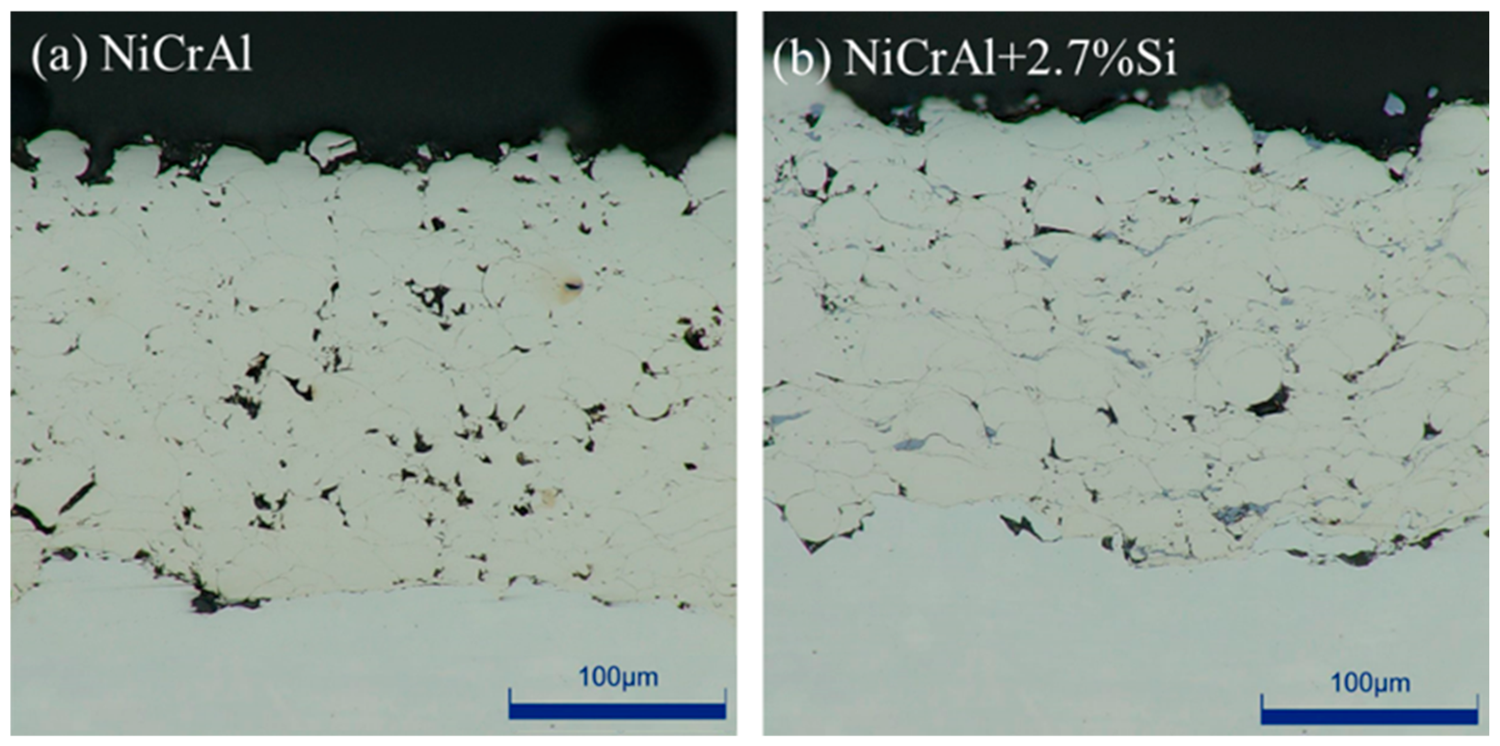
Before immersion testing, the cross-sectioned NiCrAl coatings with and without 2.7% Si addition were investigated using the optical microscope. They are shown in Figure 1a,b. Both coatings exhibit dense bulk structural coatings with low porosity. The NiCrAl coating had a thickness of 197 µm and a porosity of 3.5%, while the coating with 2.7% Si addition had a thickness of 174 µm and a porosity of 3.2%. Thickness and porosity were evaluated using ImageJ 1.52V. Although a similar coating condition was used, the thickness of the NiCrAl + 2.7% Si coating was slightly lower than that of the coating without Si addition.
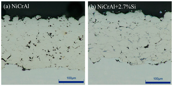
Figure 1.
Cross-sections of the coatings taken using an optical microscope: (a) NiCrAl coating, (b) 2.7% Si + NiCrAl coating.
3.2. Corrosion Test
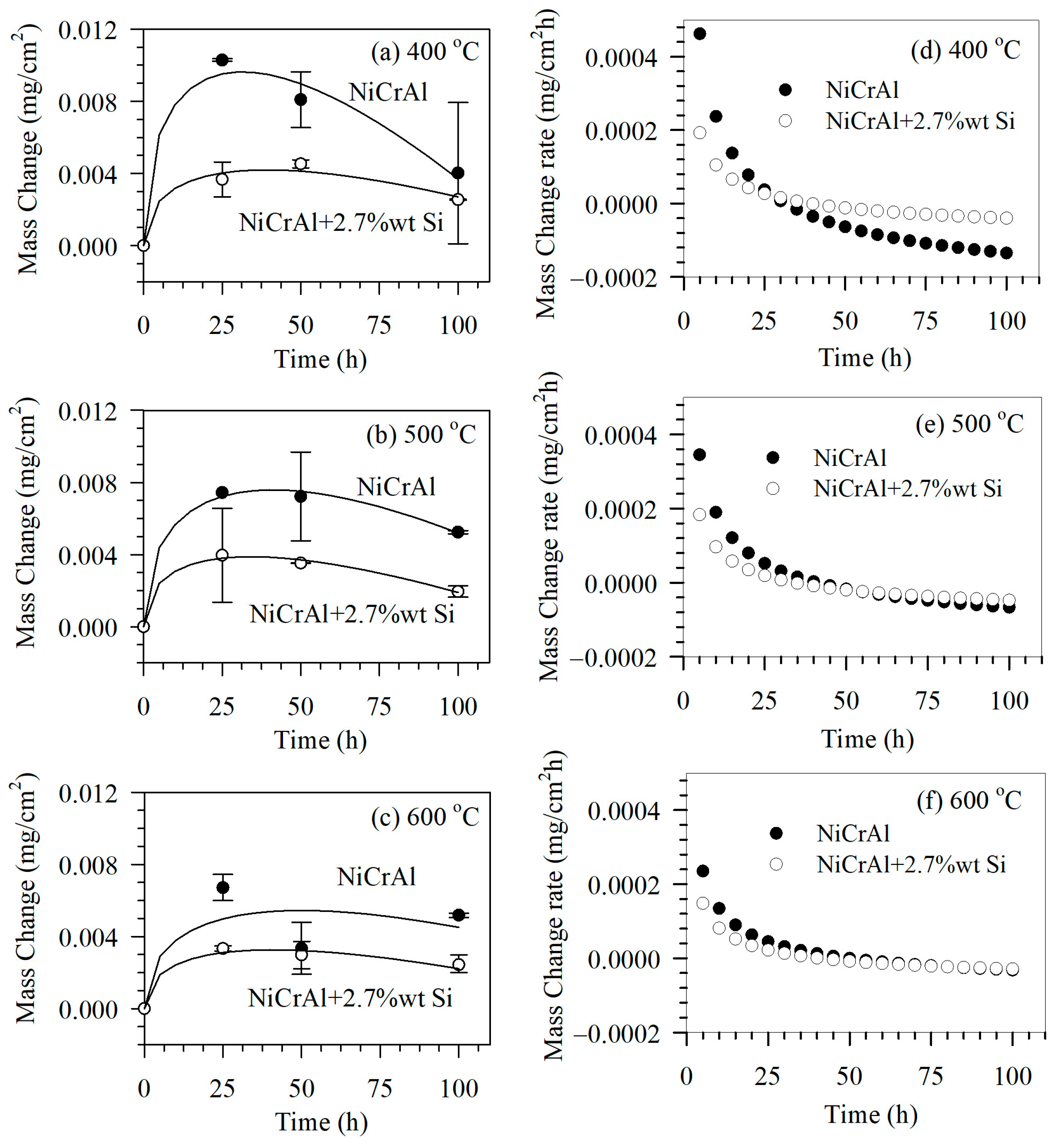
The corrosion test was conducted using immersion testing and the gravimetric method to determine mass change after exposure for 25, 50, and 100 h in the modified molten salt. The molten salt temperatures were set at 400, 500, and 600 °C. The results of immersion testing at 400, 500, and 600 °C are shown in Figure 2a–c, respectively. The mass of all samples increased after immersion in the former state (for the first 0–25 h), after which the mass change mostly exhibited a declining trend. A mass change in a sample was caused by reactions that generated reaction products or corrosion. In addition, there was mechanical adsorption of molten salt into the coating pore spaces. At lower molten salt temperatures such as 400 °C, samples gained more mass in the former state and lost more mass during the latter immersion period (25–100 h). This was compared to samples immersed in molten salt at higher temperatures, such as 500 and 600 °C. At 400 °C in the former state, this showed that the mechanism involved infiltration of molten salt into the pore spaces and an oxidation reaction. However, elevated temperatures such as 500 and 600 °C gradually made corrosion reactions more evident. This resulted in apparent less mass gain in the former state; however, the mass loss rates in the latter state at higher temperatures seemed to be limited. This indicated that corrosion reaction was governed by other factors, such as diffusion or oxidation rates.
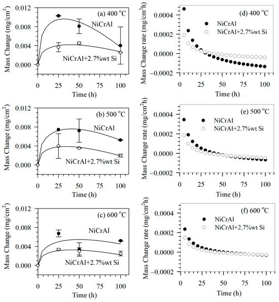
Figure 2.
Mass change of coated samples after immersion in modified molten nitrate salt mixtures at (a) 400 °C, (b) 500 °C, and (c) 600 °C and mass change rate (d) 400 °C, (e) 500 °C, and (f) 600 °C for 0, 25, 50, and 100 h.
To understand the mass gain and loss during immersion, the following model is proposed:
Here, ΔM is mass change, k1 and k2 are constants expressing mass gain and mass loss rates, respectively. The parameter t is the immersion time. The first term follows the parabolic rate law [21], which is related to the mass gain rate due to the diffusion of reactants through layers of reaction products such as oxide scales. This includes molten salt infiltration. The second term is related to linear mass loss due to corrosion reactions at the coating surface. Based on the fitting results using Equation (1) in Figure 2a–c, solid lines indicate reasonable agreement with the experimental results with correlation coefficients of more than 0.97, with the exception of NiCrAl coatings exposed to modified molten salt at 600 °C. In NiCrAl coatings, deviations from fitting results can be attributed to spallation caused by severe intergranular corrosion. This condition may develop when exposed to molten salt at 600 °C, as reported by Noparat [23].
The fitting results were analyzed based on the mass change rates, as shown in Figure 2d–f. Table 4 summarizes the parameters derived from fitting. The term k1 refers to the mass gain rates due to oxidation reactions, including the influence of molten salt infiltration and corrosion reactions. The k1 values are comparable to the mass gain rate, ΔM/Δt at 10 h, which decreases with a longer exposure time. Both values decrease as exposure temperatures increase. As mentioned, the corrosion reaction affects mass gain by reducing oxide scales. In addition, the corrosion reaction of molten salt itself removes the infiltrated molten salt. Under all conditions, as the exposure time increases, the mass gain rate eventually turns negative, which is called a mass loss rate or a corrosion rate. The mass loss rate, k2, is comparable to the mass loss rate, ΔM/Δt, at 100 h. The mass loss rates decline as exposure temperatures increase. This result indicates that the factor governing the corrosion reaction may be the formation of oxidation reaction products, such as oxide scales. At elevated temperatures, the corrosion rate decreases as oxidation reactions decline. NiCrAl coatings with 2.7% Si, mass gain, and mass loss rates (k1, k2, ΔM/Δt at 10 h and 100 h) are lower than without Si addition. In this way, Si affects the oxidation reaction and inhibits the corrosion reaction. Additionally, since the porosity of the 2.7% Si-added coating is slightly lower than that of the coating without silicon, the corrosion rates are also reduced.
Table 4.
Kinetic parameters of mass change of coated samples after immersion in modified molten nitrate salt mixtures.
According to the experimental results on the effect of Si, mass gain and loss were attenuated. As shown by the optical micrographs, adding Si does not much affect the porosity of the coatings. Thus, Si acts as a blockade of oxidation and somehow goes against molten salt infiltration through pore spaces. Gulbransen et al. showed that the kinetics of NiCr alloys at 700 to 1050 °C with low Si addition had a lower oxidation rate than with 2% Si addition [30]. Grünling and Bauer [31] reported that adding Si in NiCr alloys resulted in oxide scale formation of NiO and SiO2 with Cr2O3 precipitates at the early stage of oxidation. Although the oxidation rates were not obvious for NiCr alloys with Si addition, SiO2 blocked outward diffusion and lowered oxygen potential [31]. Anzini et al. [32] reported that adding 0.5wt% Si to Ni-based superalloy did not change the oxidation rate but promoted the creation of a continuous alumina layer beneath the surface chromia scale. The oxidation rate was higher than those without Si addition at the early state (24 h) and reduced in the long-term experiment (100 h) [33]. Thus, adding Si to coatings supported oxidation reactions. This resulted in oxidation products acting as a blockade, which limited mass gain and loss due to oxidation reaction and molten salt infiltration. It can be seen that NiCrAl coatings without Si addition have much more weight gain or loss than those with 2.7% Si addition. At 600 °C, the coating with 2.7% Si had quite a steady mass change. The experimental results also agreed with those reported by Zhang et al., whereby added Si supported the formation of the Si-rich layer. This stabilized oxide films and decreased CoCrAlSiY coating penetration depth [29].
3.3. Microstructure and Chemical Composition
To explain the corrosion behavior in the molten salt of NiCrAl coatings, SEM with EDS was further applied. Figure 3a,d show the NiCrAl coatings without and with 2.7% Si addition after immersion testing at 400 °C for 25 h. As observed using SEM, the coatings were thicker than those before testing, at 278 µm and 211 µm, respectively. This increase in thickness was likely due to the oxidation reaction and infiltration, resulting in mass gain in the former state for the coatings without Si addition. EDS analysis was conducted on both the surface and the interior of each coating, indexed as B and A, respectively. This refers to the EDS results of the samples presented in Table 5. The coating surface (region B in Table 5) accumulated more oxygen than the interior (region A in Table 5) approximately 4 times during corrosion testing at 400 °C for 25 h. As shown in the interior, the bright contrast indicated mainly Ni, Cr, and Al elements with a small amount of oxygen. In all samples tested after immersion, Na was found on the surface. A 2.7% Si addition always resulted in the detection of Si in the coatings. The detection of oxygen and Na was evidence of molten salt infiltration, as mentioned previously.
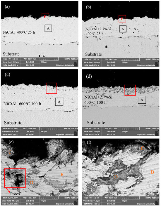
Figure 3.
Cross-section morphologies of (a) a NiCrAl-coated sample, (b) a NiCrAl + 2.7% Si-coated sample in the molten salt at 400 °C for 25 h, (c) a NiCrAl-coated sample, (d) a NiCrAl + 2.7% Si-coated sample in the molten salt at 600 °C for 100 h, (e,f) magnified cross-section morphologies of (c) and (d), respectively.
Table 5.
EDS results of Figure 3, NiCrAl 400 °C 25 h, NiCrAl 600 °C 25 h, NiCrAl + 2.7% Si 400 °C 25 h, and NiCrAl + 2.7% Si 600 °C 100 h after dipped in solar salt + 5% NaCl.
Furthermore, after immersion testing at 400 °C for 100 h, the thickness of the NiCrAl coatings without and with 2.7% Si addition decreased compared to their initial thickness before testing, at 196 µm and 168 µm, respectively. Based on the parabolic law, the thickness predicted for pure oxidation of the oxide scale at 100 h was approximately 359 µm and 248 µm, respectively. Therefore, the corrosion in molten salts led to a reduction in the thickness loss of the oxide scale, showing losses of 163 µm and 80 µm for NiCrAl coatings without and with 2.7% Si addition, respectively. After immersion testing at 600 °C for 100 h, the thickness of the NiCrAl coatings without and with 2.7% Si addition was reduced compared to before testing. Based on the parabolic law, pure oxide scale thickness at 100 h is approximately 268 µm and 203 µm. Therefore, corrosion in molten salts led to a reduction in oxide scale thickness, showing consequent losses of 118 µm and 30 µm for NiCrAl coatings without and with 2.7% Si addition.
The microstructure images for NiCrAl coatings without and with 2.7% Si addition after immersion at 600 °C for 100 h are shown in Figure 3c,d. These were used to discuss mass loss after immersion for more than 50 h. The thicknesses of the coatings decreased to approximately 268 µm and 203 µm, as observed by SEM. According to EDS, the interior areas indexed by A showed nearly the same composition as the interior of samples after immersion testing at 400 °C for 25 h. However, the SEM micrographs also show the distinctive shapes of dark gray contrast on the coating surfaces. The dark gray layer on the NiCrAl coating surface with 2.7% Si addition was clearer than the NiCrAl coating surface without Si addition. Thus, the addition of Si led to phase formation. Figure 3e,f show magnified SEM micrographs of the coating surfaces indicated by red boxes in Figure 3c,d for the NiCrAl coatings without and with 2.7% Si addition, respectively. Through EDS analysis of the bright contrast indexed by B in both Figure 3c,d, it was determined that these areas were metals or intermetallic compounds, primarily composed of Ni, Cr, and Al, with a small amount of O, as shown in Table 5. The gray contrast portions were present on the outermost surfaces and in the pore spaces of the coatings on both samples. The parts indexed by C and D (the compositions are shown in Table 5) showed O and other elements, including Ni, Al, Si, and Na. These areas primarily represented mainly oxide phases. Furthermore, a small amount of Cr was found in the oxide phase region of the NiCrAl coating without Si addition. However, no Cr was present in this region of the coating with a 2.7% Si addition. The outermost coating surfaces had a composition nearly identical to the oxides found in the pore spaces. In this region, without Si addition, Cr was likely absent or lower in content than those in the interior of the coatings. As the infiltration of molten salt occurred through pore spaces of the coatings, it was also possible to detect Na accumulated in the oxide phase region. Some pores with black contrast were detected, as shown in Figure 3e, in the NiCrAl coating without Si addition. This would explain the undulation mass change in Figure 2c caused by spallation at the NiCrAl coating surface when corrosion at the pore spaces progressed. In contrast, the pore spaces of the Si-added NiCrAl coating surface were replaced by reaction products, as shown in Figure 3f. Further, a study by other researchers reported that porosity significantly influenced coating properties. This included poor coating cohesion and a high corrosion rate [34]. As noted in the work of Alves et al. [35], who studied the effects of porosity on porous Ti corrosion behavior, more porosity exhibited an oxide film that was less stable and prone to corrosion attack. So, porosity significantly impacts the mechanical and corrosion properties of metal materials. Porosity increases the surface area exposed to the solution, thereby making the protective oxide layer less resistant to corrosion attack.
Figure 3e shows cracks caused by porosity. In the NiCrAl coating without Si addition, when the coating is exposed to molten salt, the salt is absorbed into the pore spaces and then produces some oxidation products with low corrosion resistance, such as chromium oxide. This process leads to the formation of cracks. This is compared with Figure 3f, which shows the NiCrAl coating with Si addition. Si can inhibit volatile oxides, and SiO2, present in molten salt, has higher corrosion resistance than other oxides, resulting in reduced porosity.
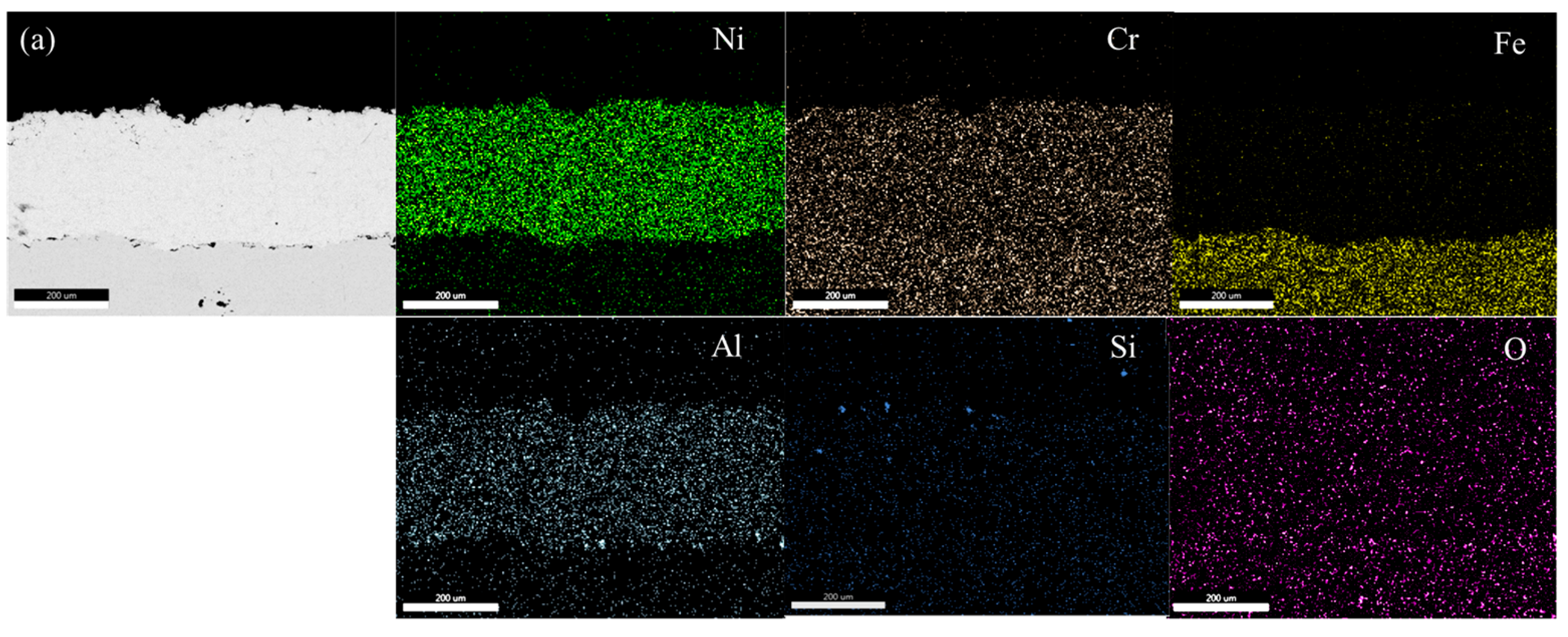
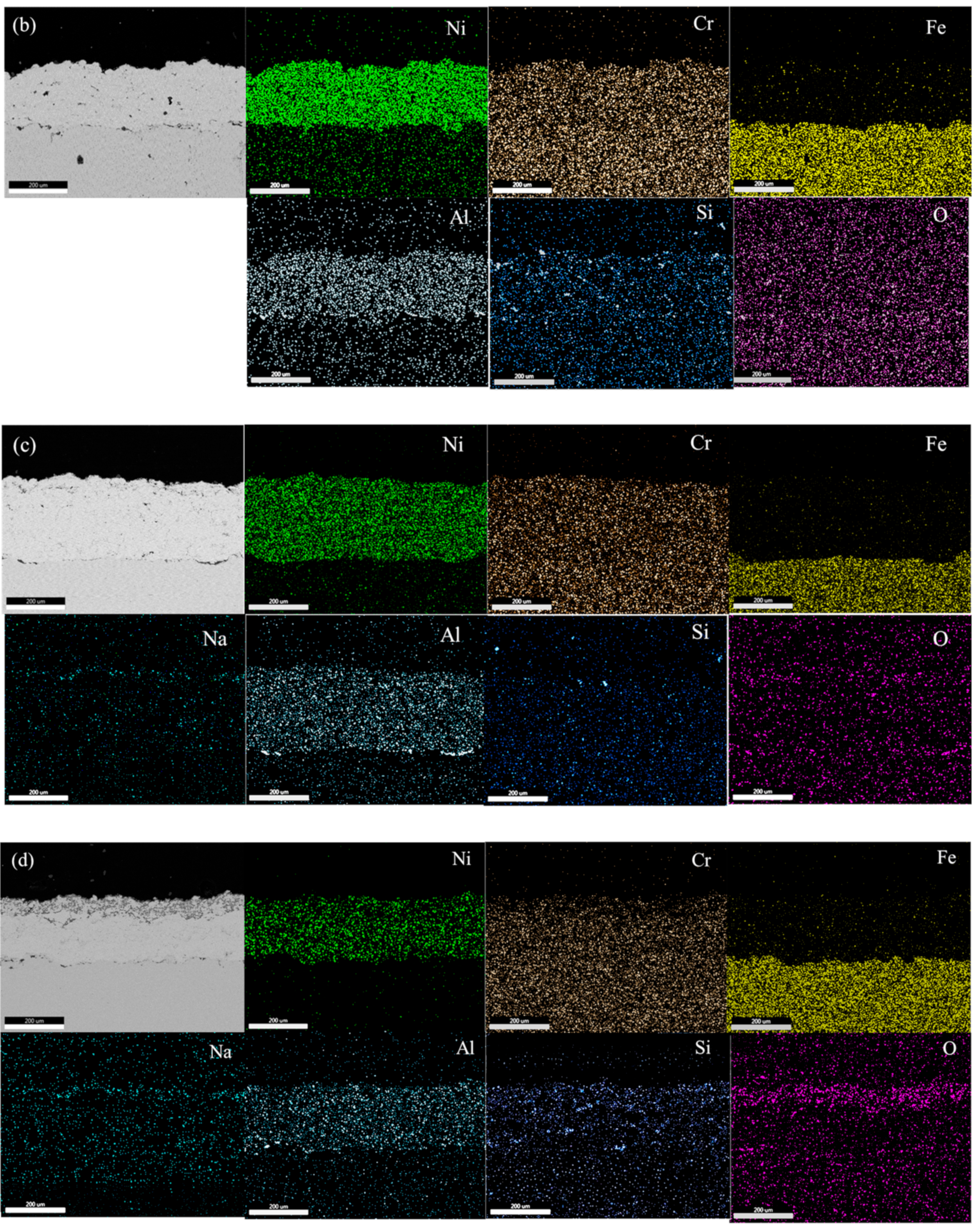
Figure 4a–d show EDS mapping images of NiCrAl and NiCrAl with 2.7% Si added coating after exposure to molten salt at 400 °C for 25 h and at 600 °C for 100 h. All coatings exhibit a uniform distribution of Ni, Cr, and Al. The presence of Si and O is hardly detectable at both exposure temperatures when the exposure time is short. When NiCrAl coating with 2.7% Si addition is exposed to molten salt at 400 °C and 600 °C for 100 h, the presence of Si and O becomes evident. Despite dispersion all over the coating, Si concentrates near the surface where O is also present. A thin Na layer is observed at the surface of NiCrAl with 2.7% Si-added coating at 600 °C, while a faint Cr layer is detected at the surface. Except for Si and O, stable oxides are rarely formed. Based on EDS mapping results, Ni, Al, Cr, Si, and Na oxides can form, but Cr2O3 appears to be unstable in molten salt environments.

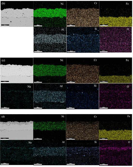
Figure 4.
EDS mapping of (a) a NiCrAl-coated sample, (b) a NiCrAl + 2.7% Si-coated sample in the molten salt at 400 °C for 25 h, (c) a NiCrAl-coated sample, (d) a NiCrAl + 2.7% Si-coated sample in the molten salt at 600 °C for 100 h.
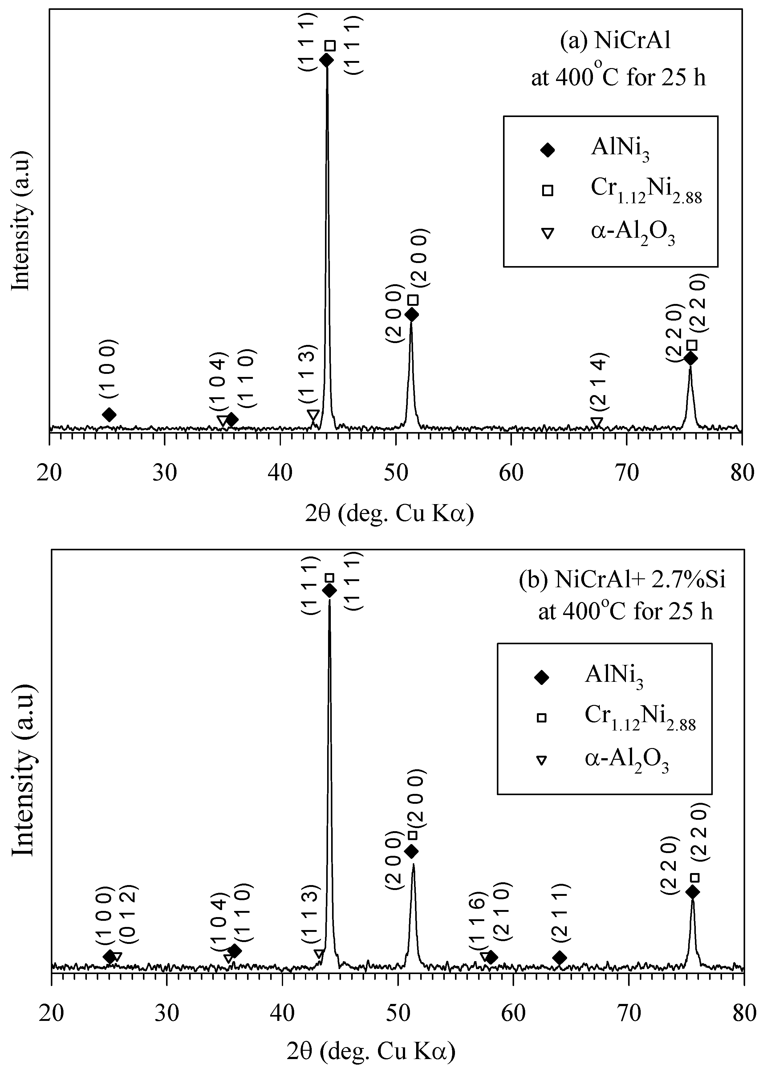
XRD analysis results in Figure 5a,b indicate the presence of AlNi3 and Cr1.12Ni2.88 phases in the coating both without and with Si addition after 25 h of immersion testing at 400 °C. These compounds are referenced from the Bruker model D8 advance database library. As mentioned previously, in the former state, there was more oxygen at the coating surfaces, and a small amount of oxide, such as α-Al2O3, possibly existed on the coating surfaces. It has been reported that a NiCr alloy with Al addition oxidized more than those without Al in an oxygen atmosphere at 700–1050 °C. Cr2O3, α-Al2O3, and MnO can form, with α-Al2O3 being the principal oxide [30]. However, the XRD peak intensity of α-Al2O3 (pattern: 00-003-1033) was quite low, indicating minimal oxidation, likely due to low oxygen partial pressure at 400 °C. Additionally, it is well-known, in the binary NaNO3-KNO3 system, the thermal decomposition of nitrate into nitrite and oxygen occurs over the temperature range of 500–620 °C [33,36,37].
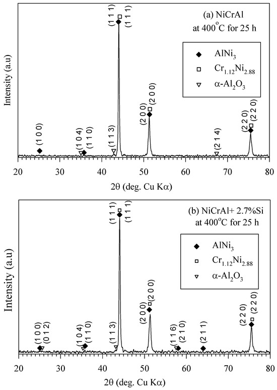
Figure 5.
XRD pattern of (a) NiCrAl and (b) NiCrAl + 2.7% Si after immersion in modified molten solar salt at 400 °C for 25 h.
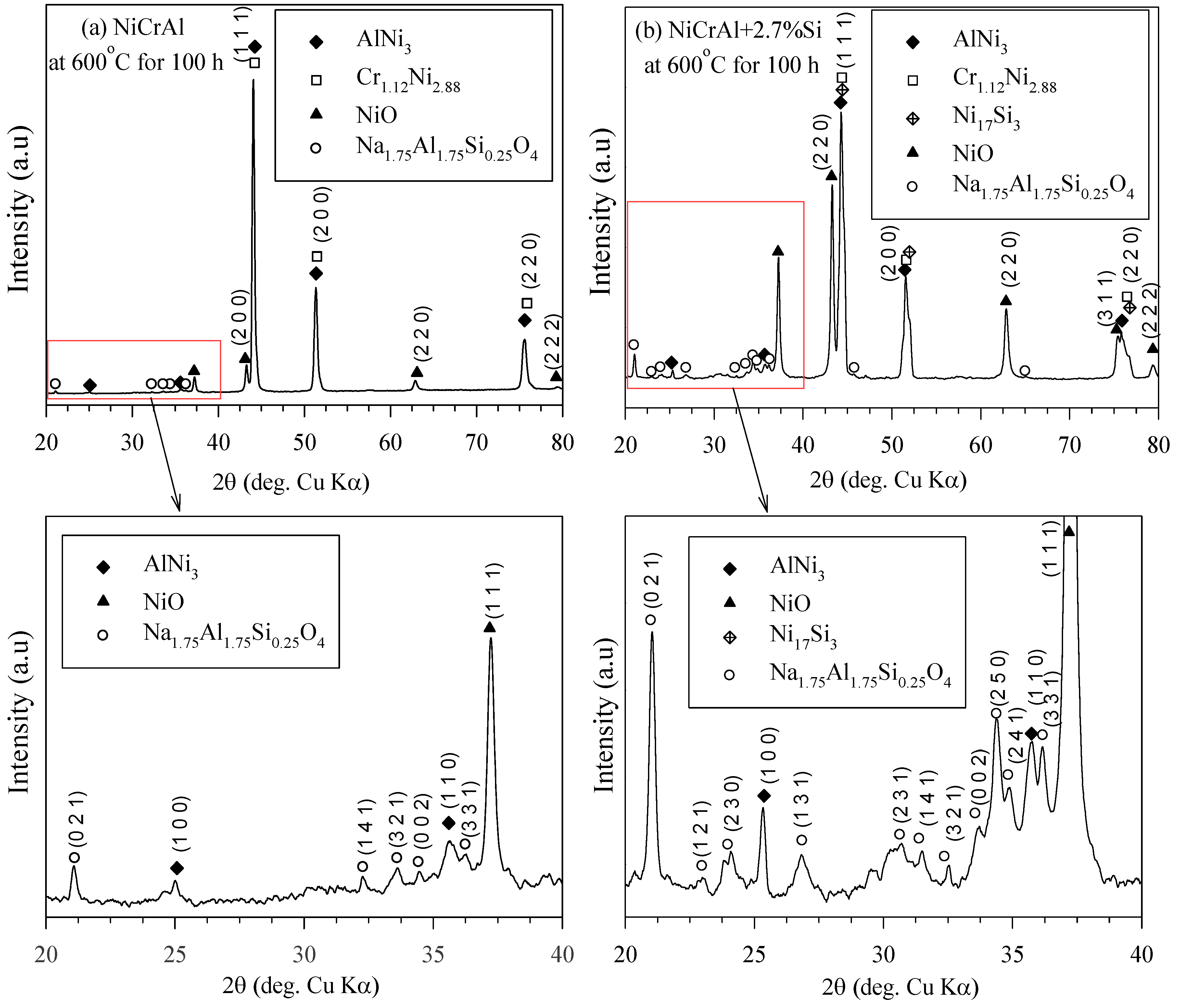
At 400 °C, oxidation is less likely to occur compared to 600 °C, based on thermal decomposition of nitrate. Figure 6a,b show the XRD analysis of the NiCrAl coatings both without and with 2.7% Si addition after immersion in molten salt at 600 °C for 100 h. AlNi3 (pattern: 03-065-0430), Cr1.12Ni2.88 (pattern: 03-065-5559), NiO (pattern: 00-047-1049), and Na1.75Al1.75Si0.25O4 (pattern: 00-049-0004) phases were detected in the coatings. Ni17Si3 (pattern: 03-065-6491) was suggested to be formed in the coating with Si addition. However, its diffraction pattern was close to those of AlNi3 and Cr1.12Ni2.88. Oxides can be formed by reaction (2), where nitrate thermal decomposition occurred intensively at temperatures above 500 °C. Despite the thermodynamic stability of Cr2O3, Al2O3, and Ni(Al,Cr)2O4 spinel [38,39], these phases were hardly present in the coatings after exposure to molten salt at 600 °C for 100 h. The absence of Cr2O3 was confirmed by both EDS and XRD analyzes, with only a small amount of Al2O3 detectable. In contrast, the relatively rapid early oxidation of Ni-15%Cr-4%Al alloys in the oxygen atmosphere at high temperatures typically results in a layer of Cr2O3, NiO, and spinel on the outer surface, with α-Al2O3 forming at the alloy–oxide interface [40]. D. J. Young reported the outer Ni(Al,Cr)2O4 spinel oxide formed by transient oxidation and α-Al2O3 beneath for Ni-based superalloys, Harnes 214 [41]. The oxidation behavior of Ni-base single-crystal superalloy AM1 indicated that transient oxidation occurred, followed by the slow formation of internal α-alumina covering the metal/oxide interface [38]. According to the previous reports, in the oxidation reactions of NiCrAl coatings during exposure at high temperatures, the transient oxides were formed while respecting the following reactions:
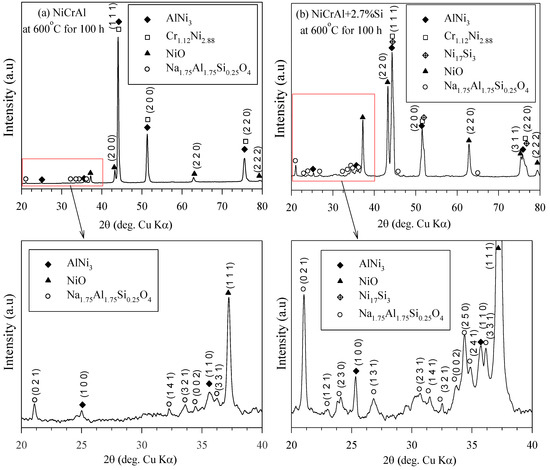
Figure 6.
XRD pattern of (a) NiCrAl and (b) NiCrAl + 2.7% Si after immersion in modified molten solar salt at 600 °C for 100 h.
The detected NiO (Reaction (5)) on the surface of NiCrAl coatings was the main oxide in the case of immersion in the modified molten solar salt at 600 °C. NiO, the only oxide formed on NiCrAl surfaces due to exposure to molten salt, was also reported by Anzini et al. [32]. Another more possibility of Al2O3 was explained due to the presence of Si additive supporting a diffuseless reaction with AlNi3 to form a protective layer of alumina [25]. The formation of SiO2 in Reaction (6) was an internal oxidation like Al2O3. Furthermore, SiO2 appeared to have better corrosion resistance than Cr2O3 and Al2O3 in molten vanadic Na2SO4 slags [31].
As aforementioned, there were corrosion reactions or leaching related to Cr in the molten salt. This phenomenon was different from reactions that occurred in the air or oxygen atmosphere at high temperatures, where Cr2O3 was stable. The corrosion of Cr2O3 in molten nitrate salts can be explained using the nitrate/nitrite equilibria adjusted by oxygen partial pressure. In addition, the decomposition reaction of nitrite to oxide ions (O2−) is shown by Reaction (7) [36].
The basic fluxing of oxide ions reacted with the oxides at the NiCrAl alloy surface and pore spaces. The product was alkaline oxides that dissolved in the salt melt. Based on the reactions, the dissolved chromia scales in the melt could be CrO22− and CrO42− [39].
While Cr2O3 forms on alloy surfaces in the air [30,38,40,41], its formation in molten salt differs because oxide ions react with Cr2O3, leading to corrosion. This behavior aligns with the fitting equation previously presented by the author, which accounts for both oxidation and mass loss. This led to the progression of pore spaces and depletion of Cr in the oxide phase regions, as detected at the surface of NiCrAl coatings without Si addition after immersion in molten salt at 600 °C. A similar situation occurred with the Si added NiCrAl coatings. Additionally, the Al2O3 and SiO2 were formed according to Reactions (4) and (6), respectively. These subsequently generated sodium–aluminum–silicate products, which replaced the pore spaces. According to the EDS and XRD results, Na1.75Al1.75Si0.25O4 was identified as the reaction product in the Si added NiCrAl coatings. The formation of this oxide can be expressed by the following reaction:
Reaction (10) is modeled after the reaction in Na2NO3 of SiO2 and Al2O3, as proposed by Xiao et al. [42]. According to the reaction, Gibbs’ free energy of −288.4 kJ⋅mol−1 at 600 °C can be derived from Kubaschewski’s thermodynamic data [43], verifying the formation of sodium–aluminum–silicate. The absence of Cr was confirmed in the oxide phase of Si added NiCrAl coatings. This can be explained by the formation and replacement of pore spaces within the oxide phase, where SiO2 acts as a blocking layer against outward diffusion [31]. This reduced the formation of Cr2O3, which has a high potential to form dissolvable chromate phases.
4. Conclusions
In this study, (0.4 and 2.7 wt%) Si additions in NiCrAl coatings on AISI 304 stainless steel were examined under exposure to modified molten nitrate salt (solar salt + 0.5%) at temperatures of 400, 500, and 600 °C for up to 100 h. The investigation concluded the following:
- When the NiCrAl coatings are exposed to modified molten nitrate salt, the mass gain and loss are more drastic at 400 °C than at 500 and 600 °C. The mass gain is due to oxidation reactions and the infiltration of molten salt, which leads to additional corrosion reactions. After prolonged exposure, oxidation products are formed and mass loss or corrosion reactions become more evident. The apparent mass gain and loss rates decline at elevated exposure temperatures. Corrosion rates depend on oxide formation and the stability of oxides forming on coating surfaces.
- The stable oxides of the coatings can be detected when exposed to modified molten salt at 600 °C. The oxidation products were NiO and sodium–aluminum–silicate, differentiated from Cr2O3, Al2O3, and Ni(Al,Cr)2O4 spinel, which formed at high-temperature exposure in air. In molten salt, Cr2O3 was volatile and dissolved in the form of chromate alkaline oxides, CrO22− and CrO42−.
- Silicon addition to the NiCrAl coating promoted the formation of Al2O3 and subsequently enhanced the formation of Na1.75Al1.75Si0.25O4, a more effective corrosion-resistant oxide. This oxide acts as a corrosion inhibitor by reducing molten salt infiltration and outward diffusion, which were the causes of corrosion progression. This resulted in a low mass change in the Si-added NiCrAl coatings.
Author Contributions
Conceptualization: T.S., P.K. and P.P.; methodology: T.S., P.K. and P.P.; formal analysis: T.S., P.K., N.K. and P.P.; writing—original draft: T.S., P.K., N.K. and P.P.; writing—review and editing: T.S., P.K. and P.P.; funding acquisition: T.S.; resources: T.S., P.K., N.K. and P.P.; supervision: P.P. All authors have read and agreed to the published version of the manuscript.
Funding
This research was funded by King Mongkut’s University of Technology North Bangkok, Thailand [Contract No. KMUTNB-FF-65-31].
Data Availability Statement
The raw data supporting the conclusions of this article will be made available by the authors on request.
Acknowledgments
The authors would like to thank King Mongkut’s University of Technology North Bangkok Department of Materials and Production Technology Engineering for laboratory support, and the Thai French institute for cooperation work laboratory support and material support. Furthermore, the authors thanks Panya Wiman for the formal analysis in this manuscript.
Conflicts of Interest
The authors declare no conflicts of interest.
References
- Ferruzzi, G.; Delcea, C.; Barberi, A.; Di Dio, V.; Di Somma, M.; Catrini, P.; Guarino, S.; Rossi, F.; Parisi, M.L.; Sinicropi, A.; et al. Concentrating Solar Power: The State of the Art, Research Gaps and Future Perspectives. Energies 2023, 16, 8082. [Google Scholar] [CrossRef]
- Alami, A.H.; Olabi, A.G.; Mdallal, A.; Rezk, A.; Radwan, A.; Rahman, S.M.A.; Shah, S.K.; Abdelkareem, M.A. Concentrating solar power (CSP) technologies: Status and analysis. Int. J. Thermofluids 2023, 18, 100340. [Google Scholar] [CrossRef]
- Zhou, Z.; Lin, A.; Wang, L.; Qin, W.; Zhao, L.; Sun, S.; Zhong, Y.; He, L.; Chen, F. Estimation of the losses in potential concentrated solar thermal power electricity production due to air pollution in China. Sci. Total Environ. 2021, 784, 147214. [Google Scholar] [CrossRef] [PubMed]
- Di Leo, S.; Pietrapertosa, F.; Salvia, M.; Cosmi, C. Contribution of the Basilicata region to decarbonisation of the energy system: Results of a scenario analysis. Renew. Sustain. Energy Rev. 2021, 138, 110544. [Google Scholar] [CrossRef]
- Goyal, N.; Aggarwal, A.; Kumar, A. Concentrated solar power plants: A critical review of regional dynamics and operational parameters. Energy Res. Soc. Sci. 2022, 83, 102331. [Google Scholar] [CrossRef]
- Canton, H.; International Energy Agency—IEA. The Europa Directory of International Organizations 2021; Routledge: Abingdon, UK, 2021; pp. 684–686. [Google Scholar] [CrossRef]
- Mueller-Steinhagen, H.; Trieb, F. Concentrating solar power, a review of the technology. Q. R. Acad. Eng. 2004, 18, 43–50. [Google Scholar]
- Bauer, T.; Breidenbach, N.; Pfleger, N.; Laing, D.; Eck, M. Overview of molten salt storage systems and material development for solar thermal power plants. In Proceedings of the World Renewable Energy Forum 2012, Denver, CO, USA, 13–19 May 2012; pp. 1–8. [Google Scholar]
- Pacio, J.; Wetzel, T. Assessment of liquid metal technology status and research paths for their use as efficient heat transfer fluids in solar central receiver systems. Sol. Energy 2013, 93, 11–12. [Google Scholar] [CrossRef]
- Fernández, A.; Rey, A.; Lasanta, I.; Mato, S.; Brady, M.; Pérez, F. Corrosion of alumina-forming austenitic steel in molten nitrate salts by gravimetric analysis and impedance spectroscopy. Mater. Corros. 2014, 65, 267–275. [Google Scholar] [CrossRef]
- Dunn, R.I.; Hearps, P.J.; Wright, M.N. Molten-salt power towers: Newly commercial concentrating solar storage. Proc. IEEE 2011, 100, 504–515. [Google Scholar] [CrossRef]
- Li, P.; Molina, E.; Wang, K.; Xu, X.; Dehghani, G.; Kohli, A.; Teja, A.S. Thermal and transport properties of NaCl–KCl–ZnCl2 eutectic salts for new generation high-temperature heat-transfer fluids. J. Sol. Energy Eng. 2016, 138, 054501. [Google Scholar] [CrossRef]
- Chen, Y.; Sun, Z.; Zhou, J. Influence of additive NaCl on the phase-change heat transfer and storage capacity of NaNO3-KNO3 mixture. Heat Technol. 2014, 32, 1–4. [Google Scholar] [CrossRef]
- Li, P.W.; Deymier, P.; Gervasio, D.; Lucas, P.; Chan, K.M.C.L.; Hao, Q.; Momayez, M. Halide and Oxy-Halide Eutectic Systems for High Performance High Temperature Heat Transfer Fluids. SunShot Concentrating Solar Power Program Review. 2013; pp. 85–86. Available online: https://www.energy.gov/sites/prod/files/2016/08/f33/04-Li_CSP-Program-Summit-presentation.pdf (accessed on 1 January 2024).
- Peng, Q.; Ding, J.; Wei, X.; Yang, J.; Yang, X. The preparation and properties of multicomponent molten salts. Apply Energy 2010, 87, 2812–2817. [Google Scholar] [CrossRef]
- Kettrakul, P.; Siripongsakul, T.; Promdirek, P. Corrosion behavior of stainless steels in molten salts used for concentrated solar power. Suranaree J. Sci. Technol. 2022, 29, 010107. [Google Scholar]
- Goods, S.H.; Bradshaw, R.W.; Prairie, M.R.; Chavez, J.M. Corrosion of Stainless and Carbon Steels in Molten Mixtures of Industrial Nitrates; Sandia National Laboratories: Livermore, CA, USA, 1994. [Google Scholar] [CrossRef]
- Bradshaw, R.W.; Goods, S.H. Corrosion Resistance of Stainless Steels during Thermal Cycling in Alkali Nitrate Molten Salts; Sandia National Laboratories: Livermore, CA, USA, 2001. [Google Scholar] [CrossRef]
- Kruizenga, A.; Gill, D. Corrosion of iron stainless steels in molten nitrate salt. Energy Procedia 2014, 49, 878–887. [Google Scholar] [CrossRef]
- Shreir, L.L.; Jarman, R.A.; Burstein, G.T. Corrosion Metal/Environment Reactions, 3rd ed.; Heinemann Ltd.: London, UK, 1994. [Google Scholar]
- Kofstad, P. High Temperature Corrosion; Elsevier: Exeter, UK, 1988. [Google Scholar]
- Ahmed, O.; Zhou, L.; Mohajeri, N.; Sohn, Y. Corrosion behaviour of AISI 304 stainless steel with solar salt heat transfer fluid. Adv. Mater. Res. 2014, 922, 13–17. [Google Scholar] [CrossRef]
- Kanjanaprayut, N.; Siripongsakul, T.; Promdirek, P. Intergranular Corrosion Analysis of Austenitic Stainless Steels in Molten Nitrate Salt Using Electrochemical Characterization. Metals 2024, 14, 106. [Google Scholar] [CrossRef]
- Ramandhany, S.; Sugiarti, E.; Desiati, R.; Martides, E.; Junianto, E.; Prawara, B.; Sukarto, A. The effect of silicon as a reactive element for NiCrAl coating performance on hastelloy substrate. In IOP Conference Series: Materials Science and Engineering, Proceedings of the 1st Materials Research Society Indonesia Conference and Congress, Yogyakarta, Indonesia, 8–12 October 2018; IOP Publishing: Bristol, UK, 2018. [Google Scholar]
- Gurrappa, I. Identification of hot corrosion resistant MCrAlY based bond coatings for gas turbine engine applications. Surf. Coat. Technol. 2001, 139, 272–283. [Google Scholar] [CrossRef]
- Yuan, K. Oxidation and Corrosion of New MCrAlX Coatings: Modelling and Experiments. Ph.D. Thesis, Linköping University Electronic Press, Linköping, Sweden, 2014. [Google Scholar]
- Smialek, J.; Jacobson, S. Oxidation of High-Temperature Aerospace Materials. In High Temperature Materials and Mechanisms, 1st ed.; CRC Press: New York, NY, USA, 2014; pp. 95–162. [Google Scholar]
- Dai, P.; Wu, Q.; Ma, Y.; Li, S.; Gong, S. The effect of silicon on the oxidation behavior of NiAlHf coating system. Appl. Surf. Sci. 2013, 271, 311–316. [Google Scholar] [CrossRef]
- Shuting, Z.; Kaiping, D.; Xianjing, R.; Ji, S. Effect of Si on Hot Corrosion Resistance of CoCrAlY Coating. Rare Met. Mater. Eng. 2017, 46, 2807–2811. [Google Scholar] [CrossRef]
- Gulbransen, E.A.; Andrew, K.F. Oxidation Studies on the Nickel-Chromium and Nickel-Chromium-Aluminum Heater Alloys. J. Electrochem. Soc. 1959, 106, 941. [Google Scholar] [CrossRef]
- Grünling, U.W.; Bauer, R. The role of silicon in corrosion-resistance high temperature coatings. Thin Solid Films 1982, 95, 3–20. [Google Scholar] [CrossRef]
- Anzini, E.; Glaenzer, N.; Mignanelli, P.M.; Hardy, M.C.; Stone, H.J.; Pedrazzini, S. The effect of manganese and silicon additions on the corrosion resistance of a polycrystalline nickel-based superalloy. Corros. Sci. 2020, 176, 109042. [Google Scholar] [CrossRef]
- Xianwei, H.; Yue, L.; Zongxin, Y.; Bingliang, G.; Zhongning, S.; Zhaowen, W. Thermal stability of sodium nitrate–sodium nitrite melts: A Raman spectra study. Spectrosc. Lett. 2018, 51, 350–355. [Google Scholar] [CrossRef]
- Oladijo, O.; Obadele, B.; Venter, A.; Cornish, L. Investigating the effect of porosity on corrosion resistance and hardness of WC-Co coatings on metal substrates. Afr. Corros. J. 2016, 2, 37–44. [Google Scholar]
- Alves, A.; Sendão, I.; Ariza, E.; Toptan, F.; Ponthiaux, P.; Pinto, A. Corrosion behaviour of porous Ti intended for biomedical applications. J. Porous Mater. 2016, 23, 1261–1268. [Google Scholar] [CrossRef]
- Federsel, K.; Wortmann, J.; Ladenberger, M. High-temperature and corrosion behavior of nitrate nitrite molten salt mixtures regarding their application in concentrating solar power plants. Energy Procedia 2015, 69, 618–625. [Google Scholar] [CrossRef]
- Nissen, D.A.; Meeker, D.E. Nitrate/nitrite chemistry in sodium nitrate-potassium nitrate melts. Inorg. Chem. 1983, 22, 716–721. [Google Scholar] [CrossRef]
- Perez, T.; Monceau, D.; Desgranges, C. Kinetic oxidation model including the transient regime for a single crystal nickel-based superalloy over the temperature range 750–1300 °C. Corros. Sci. 2022, 206, 110485. [Google Scholar] [CrossRef]
- Spiegel, M. Influence of gas phase composition on the Hot Corrosion of steels and nickel-based alloys beneath a (Ca-Na-K)-sulfate mixture containing PbSO4 and ZnSO4. Mater. Corros. 2000, 51, 303–312. [Google Scholar] [CrossRef]
- Stott, F.H.; Wood, G.H. The mechanism of oxidation of Ni-Cr-Al alloys at 1000°–1200 °C. Corros. Sci. 1971, 11, 799–812. [Google Scholar] [CrossRef]
- Young, D.J.; Chyrkin, A.; He, J.; Grüner, D.; Quadakkers, W.J. Slow transition from protective to breakaway oxidation of Haynes 214 foil at high temperature. Oxid. Met. 2013, 79, 405–427. [Google Scholar] [CrossRef]
- Xiao, H.; Cheng, Q.; Shi, H.; Li, J.; Ru, Y. The enhanced SO3 formation by alkali-metal sulfates from ash in the post-flame region during the combustion of high-alkali coal. Environ. Sci. Pollut. Res. 2020, 27, 9771–9779. [Google Scholar] [CrossRef] [PubMed]
- Kubaschewski, O.; Alcock, C.B.; Spencer, P.J. Materials Thermochemistry, 6th ed.; Great Britain: Pergamon, Turkey, 1993. [Google Scholar]

Disclaimer/Publisher’s Note: The statements, opinions and data contained in all publications are solely those of the individual author(s) and contributor(s) and not of MDPI and/or the editor(s). MDPI and/or the editor(s) disclaim responsibility for any injury to people or property resulting from any ideas, methods, instructions or products referred to in the content. |
© 2024 by the authors. Licensee MDPI, Basel, Switzerland. This article is an open access article distributed under the terms and conditions of the Creative Commons Attribution (CC BY) license (https://creativecommons.org/licenses/by/4.0/).