Article

Comparative Study of Heat Transfer Simulation and Effects of Different Scrap Steel Preheating Methods

1
College of Metallurgical and Energy, North China University of Science and Technology, Tangshan 063210, China
2
Iron and Steel Laboratory of Hebei Province, Tangshan 063210, China
3
Metallurgical and Ecological Engineering School, University of Science and Technology Beijing, Beijing 100083, China
4
College of Materials Science and Engineering, Hebei University of Science and Technology, Shijiazhuang 050018, China
*
Author to whom correspondence should be addressed.
Metals 2024, 14(8), 913; https://doi.org/10.3390/met14080913
Submission received: 10 July 2024 / Revised: 25 July 2024 / Accepted: 8 August 2024 / Published: 12 August 2024

Abstract

:
The materials charged into a converter comprise molten iron and scrap steel. Adjusting the ratio by increasing scrap steel and decreasing molten iron is a steelmaking raw material strategy designed specifically for China’s unique circumstances, with the goal of lowering carbon emissions. To maintain the converter tapping temperature, scrap must be preheated to provide additional heat. Current scrap preheating predominantly utilizes horizontal tunnel furnaces, resulting in high energy consumption and low efficiency. To address these issues, a three-stage shaft furnace for scrap preheating was designed, and Fluent software was used to compare and study the preheating efficiency of the new three-stage furnace against the traditional horizontal furnace under various operational conditions. Initially, a three-dimensional transient multi-field coupling model was developed for two scrap preheating scenarios, examining the effects of both furnaces on scrap surface and core temperatures across varying preheating durations and gas velocities. Simulation results indicate that, under identical gas heat consumption conditions, scrap achieves markedly higher final temperatures in the shaft furnace compared to the horizontal furnace, with scrap surface and core temperatures increasing notably with extended preheating times and higher gas velocities, albeit with a gradual decrease in heating rate as the scrap temperature rises. At a gas velocity of 9 m/s and a preheating time of 600 s, the shaft furnace achieves the highest waste heat utilization rate for scrap, with scrap averaging 325 °C higher than in the horizontal furnace, absorbing an additional 202 MJ of heat per ton. In the horizontal preheating furnace, scrap steel exhibits a heat absorption efficiency of 35%, whereas in the vertical furnace, this efficiency increases notably to 63%. In the vertical furnace, the waste heat recovery rate of scrap steel reaches 57%.

1. Introduction

The reduction of carbon emissions is currently a collective objective pursued by the global steel industry [1,2]. In emerging economies such as China, the advancement of converter steelmaking processes has been swift [3], with more than 90% of steel production capacity derived from blast furnace-converter extended processes. Enhancing the scrap ratio in converters [4] is critical for steel enterprises aiming to lower expenses and enhance efficiency, whether by increasing steel production, cutting carbon emissions, or reducing raw material costs during periods of favorable scrap prices. Following the heat conservation principle in converter smelting, augmenting the scrap ratio diminishes heat input, thereby necessitating the advancement of scrap preheating technologies to compensate thermally.
Numerous enterprises and researchers have extensively explored the preheating of scrap. Christian Schubert and colleagues [5] devised a rapid modeling approach to forecast continuous scrap preheating in metallurgical operations, facilitating enhanced design and control of current and future preheating systems for scrap recycling. Toulouevski and colleagues [6,7] employed high-power cyclic oxygen combustion systems, effectively meeting the demands for high-temperature scrap preheating and uninterrupted melting of molten metals. Thomas Arink and co-authors [8] utilized flue gas for metallic scrap preheating, integrating turbulent fluid dynamics and heat transfer principles in CFD models to forecast average and peak temperatures of metallic scrap relative to distinct flue gas flow rates across time. Zhuang and colleagues [9] developed a three-dimensional mathematical model via numerical simulations, elucidating the impact of pure oxygen lance parameters on ladle-based scrap preheating temperatures. Deng and colleagues [10,11] conducted simulations to assess how different types of preheated scrap perform under varying preheating temperatures and argon blowing rates when introduced into the ladle. Zhang and colleagues [12] undertook industrial trials on the “ladle addition of scrap”, studying the impacts of scrap preheating, quantity added, and residence time on steelmaking ladles, resulting in an increase in scrap content from 16% to 18% and laying the groundwork for standardized operations of “ladle addition of scrap”. Zhang and colleagues [13] conducted a modeling study on the scrap melting process in the Consteel electric arc furnace. They demonstrated how factors such as the scrap preheating temperature, scrap size, convection conditions, and scrap density influence the rate of scrap melting. Gao and colleagues [14,15] investigated how different preheating temperatures and sizes of scrap metal affect the efficiency of scrap metal melting. Zhao and colleagues [16] elucidated how preheating various types of scrap metal influences the scrap metal melting process. Zhou X, Liu M, Chen Y and colleagues [17,18,19,20] explored how varying preheating temperatures of scrap metal affect the melting process in converters and electric furnaces. Fan and colleagues [21] utilized the discrete element method to conduct numerical simulations of preheating scrap metal with high-temperature slag in a rotary drum.
Among current methods for preheating scrap, the most prominent is horizontal preheating furnace technology, depicted in Figure 1. Similar to the horizontal feeding preheating used in electric furnaces [22,23,24], this technology boasts a straightforward design, lower initial investment, and can elevate scrap temperatures to over 800 °C in just 10–20 min [25]. Nevertheless, this equipment suffers from notable drawbacks: (1) Scrap spends a brief period in the furnace, leading to uneven preheating temperatures. This results in rapid surface heating near the flame, while temperatures in the lower part of the preheating furnace and within the core of the scrap remain insufficient. (2) Moreover, the equipment suffers from unsealed feed and discharge openings, resulting in considerable heat loss outside the furnace and reduced energy efficiency. To tackle these challenges, this study introduces a three-tier vertical shaft scrap preheating system and simulates two preheating methods.

2. Establishment of the Model

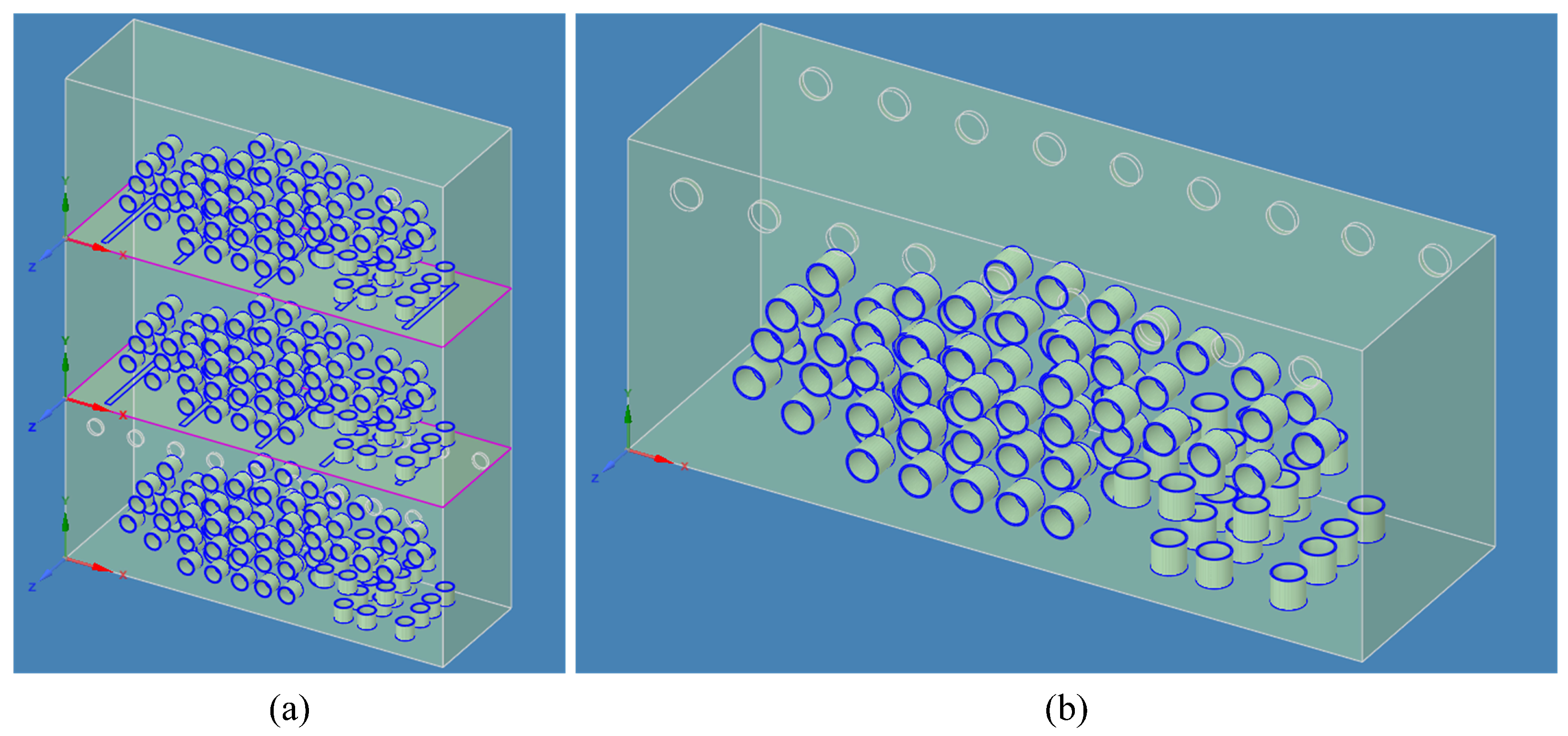
2.1. Geometric Model

In order to contrast the scrap preheating characteristics between a vertical triple-stage continuous furnace (Figure 2a) and a continuous horizontal furnace (Figure 2b), we developed two three-dimensional transient multi-field coupling models using Fluent simulation software. The dimensions and thickness of the scrap tubes were judiciously determined according to national standards and comprehensive statistical data from steel plants. Given the substantial size of the two preheating furnaces and the significant quantity of scrap they contain, a multiscale approach was employed in the modeling phase to effectively streamline the geometric representation.

2.2. Theoretical Model

The fundamental phenomena in metallurgical processes include momentum transfer, heat transfer, and mass transfer [26]. This research addresses scrap preheating through the application of the Navier–Stokes equations, the continuity equation, and the energy equation. Specifically, the continuity equation and Navier–Stokes equations are formulated as follows [27]:
ρ t + ( ρ u x ) x + ( ρ u y ) y + ( ρ u z ) z = 0
In the formula, ρ is the density, u x , u y , and u z are the velocity components in the x-, y-, and z-directions, t is time, x , y , and z denote partial derivatives with respect to x, y, and z.
( ρ v ) t + · ( ρ v v ) = p + · ( τ ) + ρ g + F
In the formula, ρ is the density, v is the velocity field of the fluid, t is time, ∇ is a gradient operator, · is a divergence operator, p is the pressure of the fluid, τ is a viscous tension or stress tensor, g is the gravitational acceleration field, and F is the sum of other external forces.
The heat transfer characteristics during the preheating of scrap steel were analyzed using the following equation:
ρ c p T t + u T x + v T y + w T z = k 2 T x 2 + 2 T y 2 + 2 T z 2 + Q
In the formula, ρ is the density, c p is the specific heat capacity, T is the temperature, t is time, u , v , w are the velocity components in the x-, y-, and z-directions, respectively, k is the thermal conductivity, x , y , z denote partial derivatives with respect to x , y , z , and Q represents heat sources or sinks.

2.3. Combustion Model

The simulation utilizes a vortex-dissipation model to characterize the chemical reaction rates of high-speed, non-premixed gas combustion within the reactor. According to this model, the production rate R i , r of species i in reaction r is determined by the lesser of Equations (4) and (5). The reaction rate in these equations is influenced by the large eddy mixing timescale, suggesting that combustion proceeds when turbulence is present ( k ϵ > 0 ) [28].
R i , r = v i , r M ω , i A ρ ϵ k min ( R ) Y R v R , r M ω , R
R i , r = v i , r M ω , i A ρ ϵ k Σ P Y P Σ j N v j , r M ω , j
In the formula, v i , r and v j , r are the stoichiometric coefficients of reactant i and product j, respectively, in reaction r, M ω , i and M ω , j are the molecular weights of species i and j, Y R represents the mass fraction of a specific reactant, Y P represents the mass fraction of any product, v R , r is the stoichiometric coefficient of a specific reactant in reaction r, M ω , R represents the molecular weight of a specific reactant, and A and B are empirical constants, with values 4.0 and 0.5.

2.4. Model Assumptions and Initial Conditions

The transport phenomena during scrap preheating in converter steelmaking are intricate, posing challenges in encapsulating all physical processes within a unified mathematical model. Considering the reliability of the established models and the reasonable computational time costs, the simulation formulated the following assumptions:
  • The high-temperature flue gas flows smoothly as a viscous, incompressible fluid through a sleek vertical shaft;
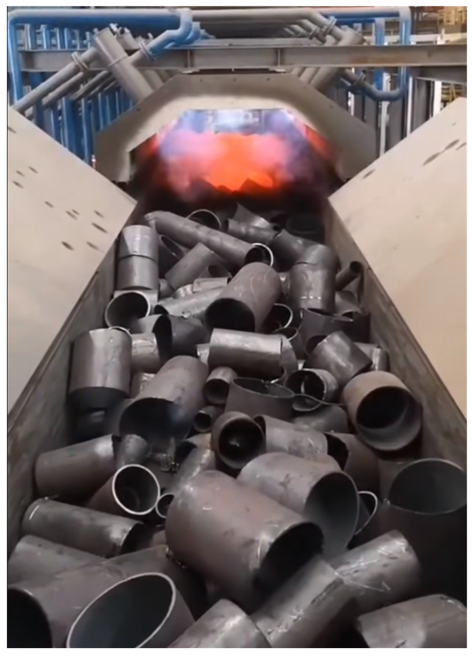
  • The scrap used in converter steelmaking varies in size and shape. Based on actual data, scrap of different thicknesses is simplified to regular, smooth circular tubes with known average dimensions of length, thickness, and inner diameter;
  • The inlet boundary flow velocity of high-temperature flue gas is uniform at the bottom of both vertical and horizontal furnaces, with all process parameters held constant, the inlet boundary flow velocity remains uniform, and all process parameters are constant without temperature variation;
  • The numerical model employs velocity inlets for both gas and oxygen inputs, each set at an inlet temperature of 25 °C. The flue gas outlet of the horizontal furnace is equipped with a pressure outlet that suppresses backflow, while the triple-stage vertical preheating furnace also utilizes a pressure outlet. The model accounts for coupled heat transfer between the gas and scrap tubes. The preheating furnace operates under standard atmospheric pressure, starting at an initial temperature of 25 °C. The inlet flue gas temperature is assumed to be constant;
  • The simulation does not account for heat released from organic combustion on the surface of scrap during preheating;
  • The gas composition consists of CO, CH 4 , H 2 , and O 2 , with mass fractions of 0.4, 0.01, 0.14, and 0.45, and a density of 0.29 kg/m3.

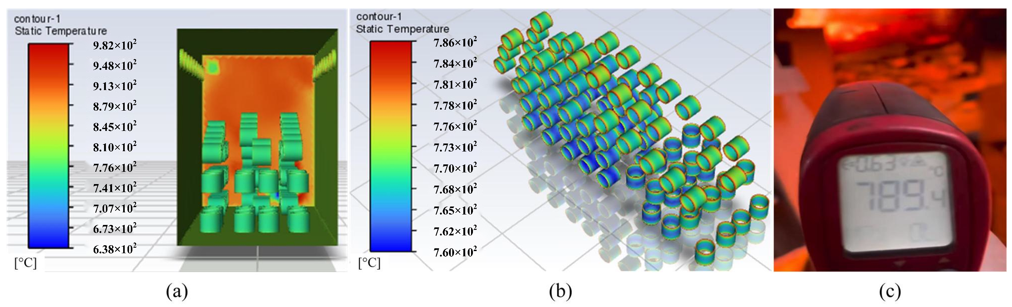
2.5. Model Results and Validation

In order to validate the accuracy of the scrap preheating simulation results, comparisons were conducted between simulated temperatures and actual production temperatures at a steel plant, as illustrated in Figure 3. The comparison reveals a close correlation between simulated temperatures and measured values, underscoring the reliability and accuracy of the simulation results. Figure 3a illustrates the comprehensive temperature distribution within the horizontal furnace, encompassing both scrap and furnace wall temperatures. Figure 3b displays the temperature distribution specifically for the scrap metal. The simulation parameters are aligned precisely with the real operational conditions. Figure 3c presents the measured outcomes, demonstrating a close match between the measured and simulated values.

3. Results and Discussion

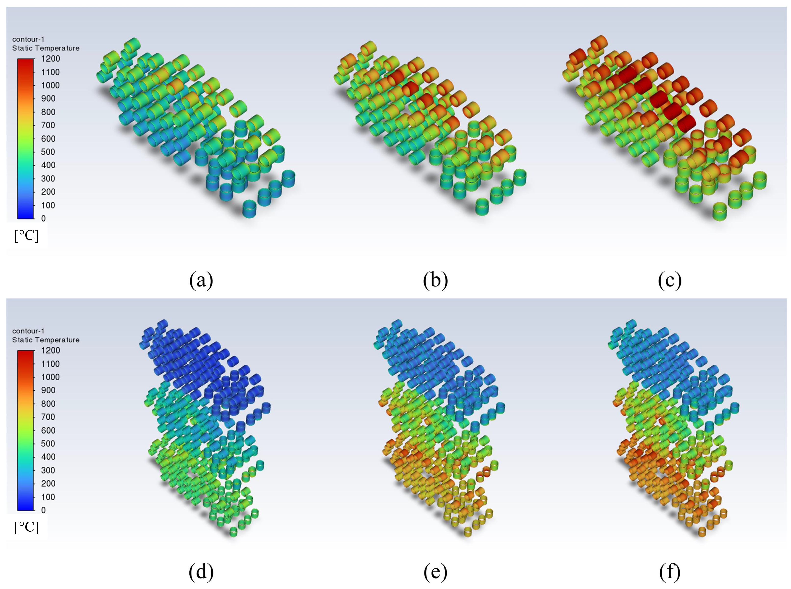
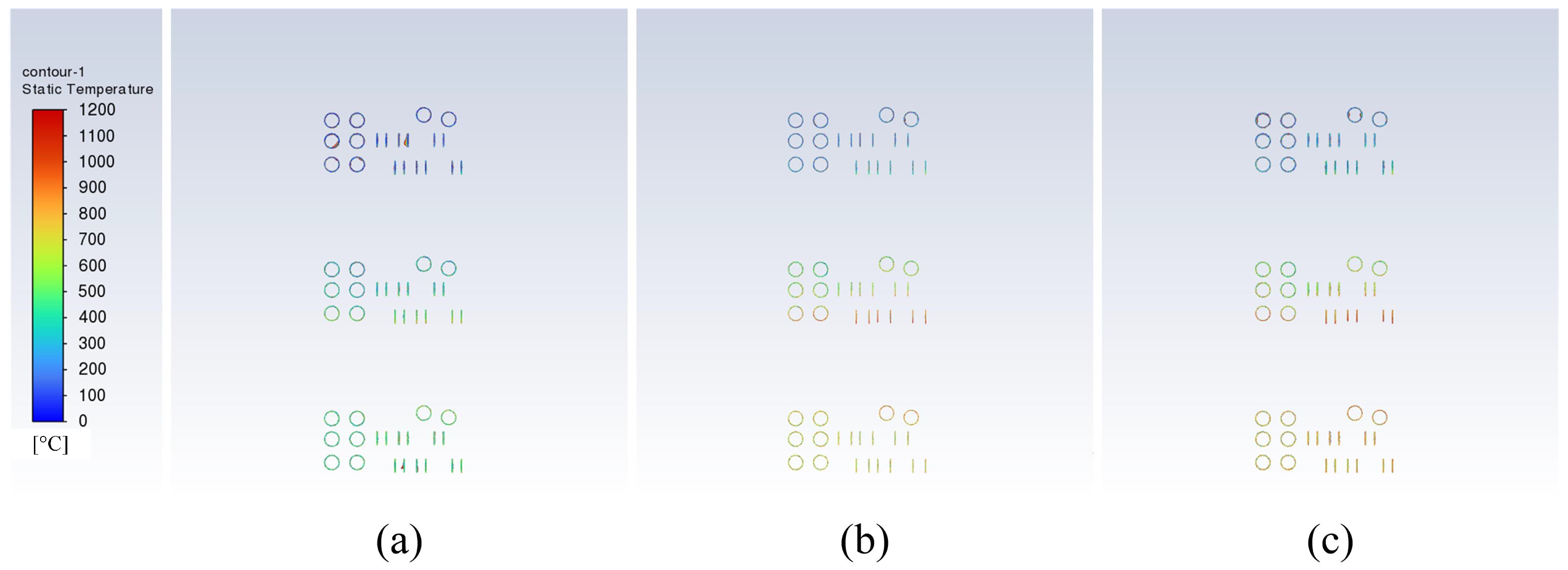
3.1. Effectiveness of Scrap Preheating at Different Preheating Times

Due to the continuous vertical preheating process, flue gas carrying waste heat from the bottom layer ascends. The middle and upper layers of scrap absorb the aforementioned waste heat. Throughout the preheating process, the upper layer undergoes three distinct stages of heat absorption. Upon completion of each heat absorption stage, the scrap descends to the subsequent layer. The top layer of the vertical furnace facilitates primary preheating, with secondary preheating occurring in the middle layer, and final preheating taking place at the bottom layer. Figure 4a–c illustrate the temperature profiles of scrap preheated for 600 s, 900 s, and 1200 s in the horizontal furnace, whereas Figure 4d–f depict the temperature distribution of scrap preheated for 600 s in the vertical furnace.
Figure 4 illustrates temperature field maps depicting the preheating process of scrap in both horizontal and vertical furnaces, under initial gas velocities of 6 m/s and durations of 600 s, 900 s, and 1200 s. Figure 4 clearly shows that the surface temperature of scrap is directly affected by the duration of preheating.
In the horizontal furnace (Figure 4a), the surface preheating temperature of scrap at 600 s predominantly ranges between 200 and 600 °C. At 900 s (Figure 4b), temperatures rise to between 500 and 900 °C. By 1200 s (Figure 4c), temperatures increase to a range of 550–950 °C. Figure 4d illustrates the final preheating temperature distribution of scrap in the vertical furnace after 600 s. Following a 600 s preheating period at room temperature, the topmost layer of scrap reaches temperatures ranging from 81 to 250 °C. As the top layer descends into the middle layer, the latter undergoes secondary preheating for 600 s, maintaining scrap temperatures between 235 and 500 °C. Subsequently, the scrap from the middle layer descends to the bottom layer, where it undergoes final preheating for 600 s, achieving temperatures ranging from 400 to 700 °C. Figure 4e depicts the final preheating temperature profile of scrap in the vertical furnace after 900 s. The furnace initially undergoes ambient temperature preheating for 900 s, raising the upper layer of scrap to temperatures ranging from 145 to 400 °C. Following a secondary preheating period of 900 s in the middle layer, scrap temperatures concentrate between 400 and 800 °C. The bottom layer undergoes final preheating lasting 900 s, achieving temperatures ranging from 600 to 1000 °C. Figure 4f displays the final preheating temperature distribution of scrap in the vertical furnace after 1200 s. The furnace experiences initial ambient temperature preheating for 1200 s, resulting in the top layer of scrap reaching temperatures ranging from 160 to 400 °C. Following a 1200 s secondary preheating period in the middle layer, scrap temperatures concentrate between 450 and 850 °C. The bottom layer undergoes a final preheating process lasting 1200 s, achieving temperatures ranging from 700 to 1100 °C. Consequently, a preliminary conclusion can be drawn that preheating temperature escalates with prolonged preheating duration, while the rate of temperature elevation in scrap diminishes gradually.

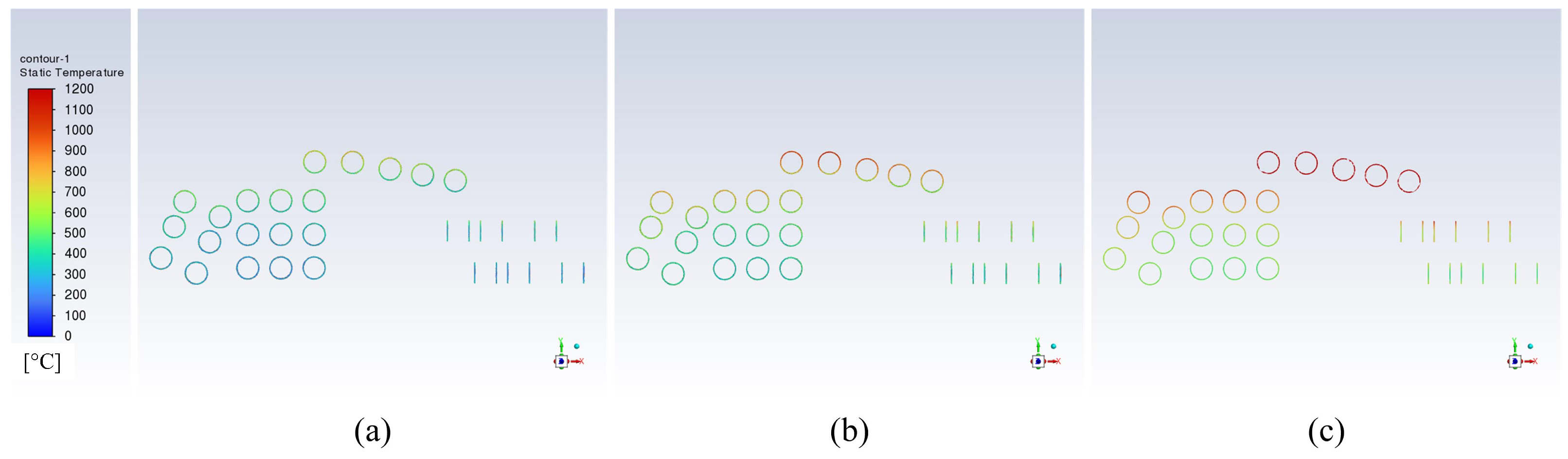
3.2. Effects of Different Initial Gas Velocities on Scrap Preheating

Figure 5 presents thermal maps illustrating scrap temperatures at 600 s during the preheating stages of horizontal and vertical furnaces, with initial gas velocities of 5 m/s, 7 m/s, and 9 m/s. Figure 5 clearly demonstrates that the surface temperature of scrap is directly affected by the initial velocity of the combustible gas.
In Figure 5a, within the horizontal preheating furnace, when the initial gas velocity is 5 m/s, the surface preheating temperature of scrap predominantly ranges from 250 to 550 °C. Figure 5b reveals that at a velocity of 7 m/s, temperatures rise to between 300 and 750 °C. Figure 5c shows that at 9 m/s, temperatures increase to between 400 and 950 °C. Figure 5d depicts the final temperature distribution in the vertical furnace with an initial inlet gas velocity of 5 m/s. Following an initial 600 s preheating period at ambient temperature, the upper layer of scrap reaches temperatures of 70–200 °C. Subsequent to a 600 s secondary preheating period in the middle layer, scrap temperatures concentrate between 150 and 400 °C. Subsequently, the middle layer scrap descends into the bottom layer, which undergoes final preheating lasting 600 s, achieving temperatures ranging from 400 to 600 °C. Figure 5e displays the final temperature distribution in the vertical furnace with an inlet gas velocity of 7 m/s. The scrap undergoes initial preheating at ambient temperature, raising the temperature of the top layer to 120–280 °C. Following secondary preheating in the middle layer, scrap temperatures concentrate between 340 and 600 °C. The bottom layer undergoes final preheating, achieving temperatures ranging from 800 to 950 °C. Figure 5f depicts the final temperature distribution in the vertical furnace with an inlet gas velocity of 9 m/s. At ambient temperature, the scrap is initially preheated, elevating the temperature of the upper layer to 180–350 °C, while the middle layer undergoes secondary preheating, resulting in scrap temperatures ranging between 400 and 700 °C. The bottom layer then undergoes final preheating, achieving scrap temperatures ranging from 800 to 1100 °C. Therefore, it can be concluded that as initial gas velocities increase, preheating temperatures rise, while the rate of temperature increase in scrap gradually declines.

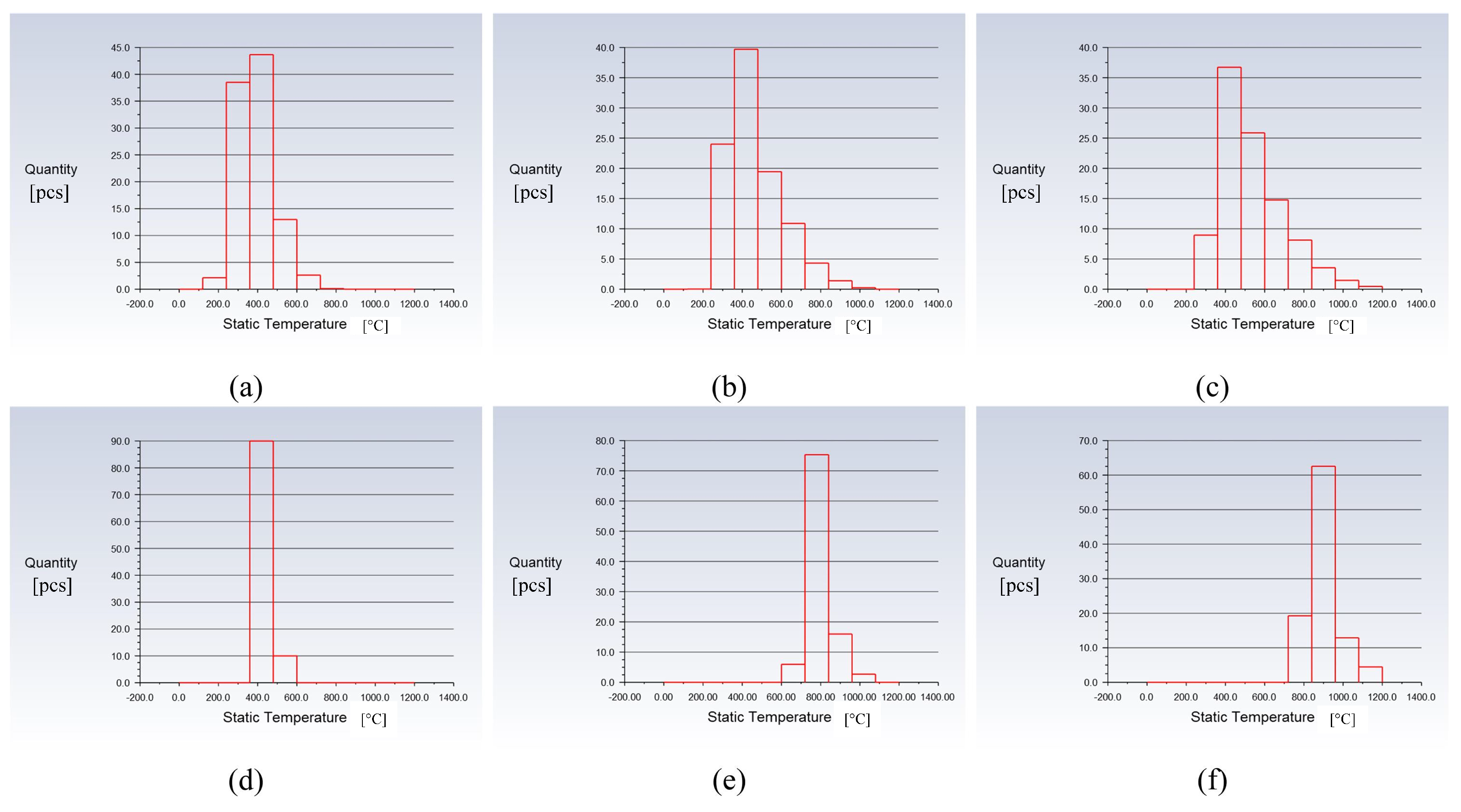
3.3. Impact of Preheating on the Core of Scrap

Figure 6 and Figure 7 illustrate how preheating affects the core temperature of scrap in both horizontal and vertical furnaces, with an initial gas velocity of 6 m/s, across various preheating durations. Figure 6a–c illustrate the core temperature profiles of scrap following preheating durations of 600 s, 900 s, and 1200 s in the horizontal furnace. Figure 7a–c display the core temperature distributions of scrap after preheating for 600 s, 900 s, and 1200 s in the vertical furnace.
In practical operation, adjustments to the flue gas velocity and preheating duration are crucial during the heating process in traditional horizontal furnaces to prevent localized overheating of scrap. Overheating can result in melting and adhesion, which, in turn, cause lower core temperatures of scrap in horizontal furnaces. In contrast, vertical furnaces effectively resolve these challenges by achieving a more consistent distribution of scrap temperatures following preheating, resulting in superior preheating outcomes.

3.4. Energy Utilization Comparison between Vertical Furnace and Horizontal Furnace

Figure 8 illustrates histograms depicting the temperatures of scrap in two types of preheating furnaces operating at identical gas velocities but varying preheating durations. Figure 8a–c illustrate how the average surface temperature of scrap steel correlates with its quantity in a horizontal preheating furnace at 600 s, 900 s, and 1200 s. Figure 8d–f demonstrate how the average surface temperature of scrap steel relates to its quantity in a vertical furnace at 600 s, 900 s, and 1200 s. Table 1 provides the average temperatures of scrap in the two types of preheating furnaces at different durations of preheating while maintaining the same initial gas velocity. The horizontal axis illustrates the average temperature of scrap steel. The vertical axis denotes the quantity of scrap steel.
Figure 9 illustrates histograms depicting the temperatures of scrap in two types of preheating furnaces, each with the same preheating duration but varying gas velocities. Figure 9a–c depict how the average surface temperature of scrap steel correlates with its quantity, under varying horizontal furnace gas velocities of 5 m/s, 7 m/s, and 9 m/s. Figure 9d–f demonstrate how the average surface temperature of scrap steel relates to its quantity, under varying vertical furnace gas velocities of 5 m/s, 7 m/s, and 9 m/s. Table 2 displays the mean temperatures of scrap in the two types of preheating furnaces with identical preheating durations but varying initial gas velocities. Six datasets are referenced to compute and compare the heat absorption capabilities between vertical and horizontal preheating furnaces.
Each layer comprises approximately 100 scrap tubes, totaling approximately 15.8 tons. The specific heat capacity of the scrap is assumed to be 0.46 kJ/(kg °C). The gas flow rate is 9.22 kg/s, and the calorific value is approximately 2.0 MJ/kg. The heat absorbed by the scrap in two types of furnaces is calculated using the specific heat capacity formula, as illustrated in Table 3 and Table 4. The heat absorbed by the scrap in two types of furnaces is calculated using the specific heat capacity formula, as specified in Table 3 and Table 4.
Table 3 and Table 4 clearly demonstrate that the heat absorption efficiency of scrap in the vertical furnace exceeds that in the horizontal furnace by a significant margin. In particular, at a gas velocity of 9 m/s and a preheating time of 600 s, the vertical furnace achieves peak waste heat recovery efficiency, absorbing an additional 202 MJ/t of scrap compared to the horizontal furnace under identical conditions, the maximum waste heat recovery rate of the vertical furnace is 57%. In the horizontal preheating furnace, scrap steel exhibits a heat absorption efficiency of 35%, whereas in the vertical furnace, this efficiency increases notably to 63%.

4. Conclusions

Numerical simulations were performed to investigate the preheating of scrap using both horizontal and vertical furnaces. The research examined how varying preheating durations and initial gas velocities impact the surface and core temperatures of the scrap. The following conclusions emerged from the study:
  • The preheating temperature of scrap increases with increased gas velocity; however, the rate of temperature rise decreases progressively under these conditions. In practical production environments with limited preheating time, appropriately increasing gas velocity can effectively raise the preheating temperature of scrap.
  • Increasing the horizontal furnace preheating time from 600 s to 1200 s results in the average surface temperature of scrap rising from 405 °C to 730 °C. Similarly, extending the vertical furnace preheating time from 600 s to 1200 s raises the surface temperature of scrap from 547 °C to 874 °C. Likewise, elevating the horizontal furnace gas velocity from 5 m/s to 9 m/s increases the surface temperature of scrap from 376 °C to 580 °C, while increasing the vertical furnace gas velocity from 5 m/s to 9 m/s boosts the surface temperature of scrap from 432 °C to 905 °C.
  • In the traditional horizontal furnace heating process, measures must be taken to restrict heating duration and exhaust gas velocity to avoid localized overheating of scrap steel, which can result in melting and adherence. As a result, during a 600 s preheating cycle, the core temperature of scrap steel typically ranges between 200 °C and 500 °C, leading to suboptimal preheating efficiency. The vertical furnaces address these concerns effectively by promoting a more even temperature distribution throughout preheated scrap steel, thereby yielding superior outcomes.
  • With an initial gas velocity of 9 m/s and a preheating duration of 600 s, the maximum waste heat recovery rate of the vertical furnace is 57%. The average temperature of scrap within the vertical furnace surpasses that of the horizontal furnace by 325 °C, absorbing an additional 202 MJ of heat per ton of scrap. In the horizontal preheating furnace, scrap steel exhibits a heat absorption efficiency of 35%, whereas in the vertical furnace, this efficiency increases notably to 63%.

Author Contributions

Conceptualization, P.X. and L.Z.; methodology, P.X., Y.J. and R.Z.; software, P.X., Y.J. and C.W.; validation, P.X., Y.J. and R.Z.; formal analysis, P.X., Y.J. and L.Z.; investigation, P.X., Y.J., L.Z. and C.W.; resources, L.Z., Y.J. and R.Z.; data curation, P.X., Y.J. and C.W.; writing—original draft preparation, P.X. and Y.J.; writing—review and editing, L.Z. and R.Z.; visualization, P.X. and Y.J.; supervision, L.Z. and R.Z.; project administration, P.X. and L.Z.; funding acquisition, P.X. and L.Z. All authors have read and agreed to the published version of the manuscript.

Funding

This research was supported by the National Key Fund Projects of China (No. U21A20114) and the Hebei Provincial Science and Technology Programme of China (No. 23561007D).

Data Availability Statement

The data presented in this study are available on request from the corresponding author. The data are not publicly available due to privacy restrictions.

Acknowledgments

The author acknowledges the HBIS Company Limited and Steel Laboratory of Hebei Province in this study. Their generous sponsorship and technical support provided crucial resources for experiments, significantly advancing the progress and outcomes of the research.

Conflicts of Interest

The authors declare no conflicts of interest.

References

  1. Voraberger, B.; Wimmer, G.; Dieguez Salgado, U.; Wimmer, E.; Pastucha, K.; Fleischanderl, A. Green LD (BOF) Steelmaking—Reduced CO2 Emissions via Increased Scrap Rate. Metals 2022, 12, 466. [Google Scholar] [CrossRef]
  2. Hao, H.; Wu, H.; Wei, F.; Xu, Z.; Xu, Y. Scrap Steel Recycling: A Carbon Emission Reduction Index for China. Sustainability 2024, 16, 4250. [Google Scholar] [CrossRef]
  3. Wang, X.; Wang, H. Converter practice in China with respect to steelmaking and ferroalloys. Miner. Process. Extr. Metall. 2019, 128, 46–57. [Google Scholar] [CrossRef]
  4. Gao, M.; Gao, J.T.; Zhang, Y.L.; Yang, S.F. Two-dimensional temperature distribution and heat transfer during scrap melting. JOM 2020, 72, 1943–1952. [Google Scholar] [CrossRef]
  5. Schubert, C.; Büschgens, D.; Eickhoff, M.; Echterhof, T.; Pfeifer, H. Development of a Fast Modeling Approach for the Prediction of Scrap Preheating in Continuously Charged Metallurgical Recycling Processes. Metals 2021, 11, 1280. [Google Scholar] [CrossRef]
  6. Toulouevski, Y.N.; Zinurov, I.Y. Methods of realization of high-temperature scrap preheating. In Electric Arc Furnace with Flat Bath: Achievements and Prospects; Springer: Berlin/Heidelberg, Germany, 2015; pp. 69–82. [Google Scholar] [CrossRef]
  7. Toulouevski, Y.N.; Zinurov, I.Y. High-Temperature Heating a Scrap in a Furnace Shaft. In Fuel Arc Furnace (FAF) for Effective Scrap Melting: From EAF to FAF; Springer: Berlin/Heidelberg, Germany, 2017; pp. 79–85. [Google Scholar] [CrossRef]
  8. Arink, T.; Hassan, M.I. Metal scrap preheating using flue gas waste heat. Energy Procedia 2017, 105, 4788–4795. [Google Scholar] [CrossRef]
  9. Zhuang, S.; Zhan, D.; Wang, T.; Li, P.; Yang, Y. Influence of Oxy-Fuel Lance Parameters on the Scrap Pre-Heating Temperature in the Hot Metal Ladle. Metals 2023, 13, 847. [Google Scholar] [CrossRef]
  10. Zhang, L.; Fang, Q.; Zhou, W.; Wang, J.; Yu, G.; Zhang, H.; Ni, H. Numerical simulation on the melting behaviors of steel scrap in a ladle with bottom argon blowing. Chin. J. Eng. 2024, 46, 822–834. [Google Scholar] [CrossRef]
  11. Deng, S.; Xu, A.; Yang, G.; Wang, H. Analyses and calculation of steel scrap melting in a multifunctional hot metal ladle. Steel Res. Int. 2019, 90, 1800435. [Google Scholar] [CrossRef]
  12. Zhang, C.; Ding, P.; Wang, K.; Huang, J.; Zhang, J. Feasibility Study on Ladle with Scrap Add Iron. Metals 2017, 4, 186–192. [Google Scholar] [CrossRef]
  13. Zhang, H.; Wei, G.; Xu, A.; Wang, C.; Zhu, R. Modelling and Simulation of the Scrap Melting in the Consteel EAF. In TMS Annual Meeting & Exhibition, Proceedings of the TMS Annual Meeting & Exhibition, Orlando, FL, USA, 3–7 March 2024; Springer Nature Switzerland: Basel, Switzerland, 2024; pp. 537–547. [Google Scholar] [CrossRef]
  14. Gao, M.; Yang, S.F.; Zhang, Y.L. Experimental study on mass transfer during scrap melting in the steelmaking process. Ironmak. Steelmak. 2020, 47, 1006–1014. [Google Scholar] [CrossRef]
  15. Gao, M.; Gao, J.T.; Zhang, Y.L.; Yang, S.F. Simulation on scrap melting behavior and carbon diffusion under natural convection. Int. J. Miner. Metall. Mater. 2021, 28, 380–389. [Google Scholar] [CrossRef]
  16. Zhao, A.N.; Zhang, L.Q.; Zhang, B.L.; Yang, W.O.; Ali, N.; Zhang, W.; Zhang, C.J. The Study on the Behavior of the Melting Process of Scraps in Converter. Int. J. Res. Stud. Sci. Eng. Technol. 2020, 7, 15–21. [Google Scholar]
  17. Zhou, X.B.; Wang, W.X.; Di, Z.X.; He, Q.L.; Yue, Q. Numerical investigation of scrap melting in high-carbon hot metal. Int. J. Chem. React. Eng. 2022, 20, 1107–1116. [Google Scholar] [CrossRef]
  18. Liu, M.; Ma, G.J.; Zhang, X.; Zheng, D. Numerical simulation on the melting kinetics of steel scrap in iron-carbon bath. Case Stud. Therm. Eng. 2022, 34, 101995. [Google Scholar] [CrossRef]
  19. Chen, Y.C.; Ryan, S.; Silaen, A.K.; Zhou, C.Q. Simulation of scrap melting process in an AC electric arc furnace: CFD model development and experimental validation. Metall. Mater. Trans. B 2022, 53, 2675–2694. [Google Scholar] [CrossRef]
  20. Chen, Y.C.; Luo, Q.X.; Ryan, S.; Busa, N.; Silaen, A.K.; Zhou, C.Q. Effect of coherent jet burner on scrap melting in electric arc furnace. Appl. Therm. Eng. 2022, 212, 118596. [Google Scholar] [CrossRef]
  21. Fan, G.Y.; Su, F.Y.; Zhao, Q.L.; Li, C.W.; Li, B. Study on Heat Transfer Process between High-Temperature Slag Particles and Scrap in Drum Based on DEM Method. Processes 2024, 12, 815. [Google Scholar] [CrossRef]
  22. Grasselli, A.; Reali, S.; Andersson, J.; Lehman, A.F.; Teng, L. Consteerrer™ technology: Getting the most out of the electric steelmaking process. In Proceedings of the 4th European Conference on Clean Technologies in the Steel Industry, Bergamo, Italy, 28–29 September 2018. [Google Scholar]
  23. Toulouevski, Y.N.; Zinurov, I.Y. Analysis of technologies and designs of the EAF as an aggregate for heating and melting of scrap. In Fuel Arc Furnace (FAF) for Effective Scrap Melting: From EAF to FAF; Springer: Berlin/Heidelberg, Germany, 2017; pp. 7–39. [Google Scholar] [CrossRef]
  24. Hu, H.; Yang, L.; Wei, G.; Zou, Y.; Xue, B.; Chen, F.; Wang, S.; Guo, Y. Numerical Simulation of Scrap Preheating with Flue Gas in EAF Steelmaking Process. In TMS Annual Meeting & Exhibition, Proceedings of the TMS Annual Meeting & Exhibition, Orlando, FL, USA, 3–7 March 2024; Springer Nature Switzerland: Basel, Switzerland, 2024; pp. 569–577. [Google Scholar] [CrossRef]
  25. Makarov, A.N. Effect of the architecture on energy efficiency of electric arc furnaces of conventional and Consteel designs. Metallurgist 2019, 62, 882–891. [Google Scholar] [CrossRef]
  26. Odenthal, H.-J.; Kemminger, A.; Krause, F.; Sankowski, L.; Uebber, N.; Vogl, N. Review on Modeling and Simulation of the Electric Arc Furnace (EAF). Steel Res. Int. 2017, 89, 1700098. [Google Scholar] [CrossRef]
  27. Lu, S.-L.; Xiao, F.-R.; Guo, Z.-H.; Wang, L.-J.; Li, H.-Y.; Liao, B. Numerical simulation of multilayered multiple metal cast rolls in compound casting process. Appl. Therm. Eng. 2016, 93, 510–519. [Google Scholar] [CrossRef]
  28. Nakanishi, K.; Szekely, J. Deoxidation kinetics in a turbulent flow field. Trans. ISIJ 1975, 15, 522–530. [Google Scholar] [CrossRef]
Figure 1. Horizontal preheating furnace.
Metals 14 00913 g001
Figure 2. Two types of preheating furnace models. (a) Vertical triple-stage continuous furnace. (b) Continuous horizontal furnace.
Metals 14 00913 g002
Figure 3. Comparison of simulation results from the horizontal furnace model with actual temperature measurements. (a) The temperature inside the horizontal furnace model. (b) The temperature of scrap steel inside the horizontal furnace model. (c) Measured temperature.
Metals 14 00913 g003
Figure 4. Preheating effectiveness of scrap at different times in two types of preheating furnaces. (a) The temperature distribution following a 600 s preheating period in the horizontal furnace. (b) The temperature distribution following a 900 s preheating period in the horizontal furnace. (c) The temperature distribution following a 1200 s preheating period in the horizontal furnace. (d) The temperature distribution following a 600 s preheating period in the vertical furnace. (e) The temperature distribution following a 900 s preheating period in the vertical furnace. (f) The temperature distribution following a 1200 s preheating period in the vertical furnace.
Metals 14 00913 g004
Figure 5. Two different types of preheating furnaces with varying initial velocities of combustible gases and their impact on the preheating of scrap. (a) The temperature field with a gas velocity of 5 m/s in the horizontal furnace. (b) The temperature field with a gas velocity of 7 m/s in the horizontal furnace. (c) The temperature field with a gas velocity of 9 m/s in the horizontal furnace. (d) The temperature field with a gas velocity of 5 m/s in the vertical furnace. (e) The temperature field with a gas velocity of 7 m/s in the vertical furnace. (f) The temperature field with a gas velocity of 9 m/s in the vertical furnace.
Metals 14 00913 g005
Figure 6. Preheating effect of scrap cores under different preheating times in horizontal preheating furnace. (a) Temperature field of scrap cores preheated for 600 s in a horizontal furnace. (b) Temperature field of scrap cores preheated for 900 s in a horizontal furnace. (c) Temperature field of scrap cores preheated for 600 s in a horizontal furnace.
Metals 14 00913 g006
Figure 7. Preheating effect of scrap cores under different preheating times in horizontal preheating furnace. (a) Temperature field of scrap cores preheated for 600 s in a vertical furnace. (b) Temperature field of scrap cores preheated for 900 s in a vertical furnace. (c) Temperature field of scrap cores preheated for 1200 s in a vertical furnace.
Metals 14 00913 g007
Figure 8. Temperature of scrap at different times in two types of preheating furnaces at the same gas velocity. (a) Temperature of scrap preheated for 600 s in a horizontal furnace. (b) Temperature of scrap preheated for 900 s in a horizontal furnace. (c) Temperature of scrap preheated for 1200 s in a horizontal furnace. (d) Temperature of scrap preheated for 600 s in a vertical furnace. (e) Temperature of scrap preheated for 900 s in a vertical furnace. (f) Temperature of scrap preheated for 1200 s in a vertical furnace.
Metals 14 00913 g008
Figure 9. Temperature of scrap at different gas velocities in two types of preheating furnaces at the same time. (a) Temperature of scrap in the horizontal furnace when gas velocity is 5 m/s. (b) Temperature of scrap in the horizontal furnace when gas velocity is 7 m/s. (c) Temperature of scrap in the horizontal furnace when gas velocity is 9 m/s. (d) Temperature of scrap in the vertical furnace when gas velocity is 5 m/s. (e) Temperature of scrap in the vertical furnace when gas velocity is 7 m/s. (f) Temperature of scrap in the vertical furnace when gas velocity is 9 m/s.
Metals 14 00913 g009
Table 1. Comparison of average scrap temperatures at different times in two types of preheating furnaces at the same gas velocity.
Time/sThe Temperature of the Scrap in the Horizontal Furnace/°CThe Temperature of the Scrap in the Vertical Furnace/°C
600405547
900513806
1200730874
Table 2. Comparison of average scrap temperatures at different gas velocities in two types of preheating furnaces at the same time.
Initial Velocity/m/sThe Temperature of the Scrap in the Horizontal Furnace/°CThe Temperature of the Scrap in the Vertical Furnace/°C
5376432
7509801
9555915
Table 3. Heat absorption of scrap at different times in two types of preheating furnaces at the same gas velocity.
Time/sThe Heat Absorption of Scrap in the Horizontal Furnace/MJThe Heat Absorption of Scrap in the Vertical Furnace/MJ
60027614448
90035477020
120066837406
Table 4. Heat absorption of scrap at different gas velocities in two types of preheating furnaces at the same time.
Initial Velocity/m/sThe Heat Absorption of Scrap in the Horizontal Furnace/MJThe Heat Absorption of Scrap in the Vertical Furnace/MJ
525503430
735186140
938527050
Disclaimer/Publisher’s Note: The statements, opinions and data contained in all publications are solely those of the individual author(s) and contributor(s) and not of MDPI and/or the editor(s). MDPI and/or the editor(s) disclaim responsibility for any injury to people or property resulting from any ideas, methods, instructions or products referred to in the content.

