Abstract
Vanadis 4E (V4E) is a powder metallurgical cold work tool steel predominantly used in application with demand for wear resistance, high hardness, and toughness. It is of interest to have a processing route that enables full density starting from clean gas-atomized powder allowing component shaping capabilities. This study presents a process involving freeze granulation of powder to facilitate compaction by means of cold isostatic pressing, followed by sintering to allow for capsule-free hot isostatic pressing (HIP) and subsequent heat treatments of fully densified specimens. The sintering stage has been studied in particular, and it is shown how sintering in pure nitrogen at 1150 °C results in predominantly closed porosity, while sintering at 1200 °C gives near full density. Microstructural investigation shows that vanadium-rich carbonitride (MX) is formed as a result of the nitrogen uptake during sintering, with coarser appearance for the higher temperature. Nearly complete densification, approximately 7.80 ± 0.01 g/cm3, was achieved after sintering at 1200 °C, and after sintering at 1150 °C, followed by capsule-free HIP, hardening, and tempering. Irrespective of processing once the MX is formed, the nitrogen is locked into this phase and the austenite is stabilised, which means any tempering tends to result in a mixture of austenite and tempered martensite, the former being predominate during the sequential tempering, whereas martensite formation during cooling from austenitization temperatures becomes limited.
1. Introduction
Tool steels are widely used in various high-performance applications such as blanking, stamping, and punching due to their excellent characteristic properties including high hardness, adequate abrasive resistance, and toughness [1,2]. Based on the specific application, these tool steels were categorized into various operating conditions such as forging, die casting, and high-speed machining [3,4,5]. The need for high-performance applications such as cold extrusion tooling, knives, and powder pressing dies requires a good combination of wear resistance, hardness, ductility, and toughness; thus, modern powder metallurgical (PM) cold work tool steels have been developed, such as Vanadis 4 [6,7,8,9]. These steels are normally fabricated by means of hot isostatic pressing of the encapsulated spherically shaped gas-atomized powder, whereby excellent properties and full density is achieved as a result of more homogenous material compared to cast and wrought alternatives. Notably, this also means that the consolidated material is provided as a preform from which the actual final product must be realised by subsequent machining and heat treatments.
At the other end of powder metallurgical processing, there is the classical press and sinter route that provides net-shape components. This route uses irregular-shaped water-atomized powder for the compaction stage, to provide for the necessary mechanical locking and green strength of the compact [10,11]. This processing route is, however, not well suited for reaching full density, as the practical sintering of such compacts to full density without use of liquid phase sintering is hardly possible. Consequently, various approaches to improve the densification have been addressed with ranges of success [10,12,13,14].
In the case of tool steels, even if water-atomized powder, despite limited compressibility, could be compacted to a certain degree, the highly specific surface area of such powder brings challenges with respect to high oxygen content and alloying element content, which trigger oxide residual in the final material. In contrast, gas-atomized tool steel powder has less oxygen contents but is hard to compact due its poor compressibility [15,16,17]. To counteract this challenge, binder can be mixed with the powder to facilitate compaction [18]. Provided that subsequent debinding and sintering can be tailored to limit oxygen content and reach closed porosity [10], the utilization of capsule-free HIP as the final stage is beneficial to achieve full densification after the sintering. This also opens up for net-shape component manufacturing.
Carbides formed within the microstructure of tool steels significantly contribute to defining their mechanical properties. The type and morphology of these carbides determine the performance characteristics of the tool steels. Primary carbides influence mostly on the wear resistance and toughness, whereas the secondary carbides precipitated during tempering treatment controls the overall hardness in applications. The MC, M2C, and M6C are categorized as primary carbides [19]. Sintering of powder metallurgical tool steels has been shown to be viable to reach near full density when conducted in nitrogen atmosphere, owing to the expansion of the solidus-liquidus temperature span [20], whereby supersolidus can be better controlled. The reason behind this expansion is the expel of carbon to the matrix associated lowering of the solidus temperature as nitrogen is absorbed in the material with progressive transformation of MC to M(C,N) [21]. In addition, tool steels containing nitrogen exhibit excellent wear and tribological properties [21,22,23,24,25].
Thus, to combine potential net-shape capabilities with full density processing starting from gas-atomized V4E tool steel powder, a novel approach is explored in this study involving powder granulation, cold isostatic pressing (CIP), nitrogen sintering, and hot isostatic pressing with controlled cooling. The powder granules are realized through the freeze granulation (FG) technique. The CIP cannot facilitate high green densities. Consequently, densification during sintering is a key measure. Based on theoretical predictions, sintering has been explored at two different temperatures of 1150 °C and 1200 °C in pure nitrogen atmosphere. Finally, sintered variants are subjected to capsule-free hot isostatic pressing, followed by nominal hardening and tempering runs. The outcome of this novel processing route is explored with respect to achievable full densification of the powder metallurgical V4E tool steel, microstructure control, and potential properties.
2. Materials and Methods
2.1. Materials
Gas-atomized V4E tool steel powder with size distribution of <20 µm is provided by Uddeholms AB, Hagfors, Sweden. Nominal chemical composition of the powder grade is given below in Table 1.

Table 1.
Chemical composition (in wt.%) of gas-atomized V4E tool steel powder, adapted from Ref. [26].
2.2. Freeze Granulation (FG)
Granules were prepared using 25 vol.% of Halt B-26 binder through freeze granulation (FG), as shown in Figure 1. Granules were prepared by pouring the suspension containing powder into a chamber filled with liquid nitrogen under high-pressure air, resulting in the granules being coated with liquid nitrogen on their surfaces. Next, the frozen granules were collected and transferred for freeze drying, initiating the sublimation process, ultimately resulting in the production of freeze-dried granules with preserved homogeneity.
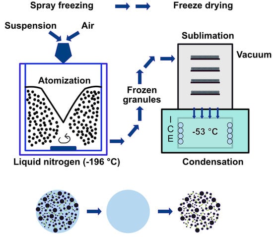
Figure 1.
Schematic illustration of freeze granulation (FG) method.
2.3. Cold Isostatic Pressing (CIP)
The granules were pre-compacted uniaxially to cylindrical form at 20 MPa (see Figure 2a), before being placed in a sealed vacuum bag for CIP process (see Figure 2c). As can be seen in Figure 2b below, these pre-compacted samples were then subjected to CIP process at 300 MPa for 120 s using an in-house cold isostatic press, Avure Technologies at RISE AB, Mölndal, Sweden. All the CIP processed cylindrical samples were produced in dimensions of 10 mm in height and 10 mm in diameter, respectively.
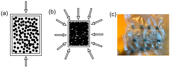
Figure 2.
(a) Uniaxial pressing of granules, (b) isostatic pressing of the pre-pressed sample, and (c) samples in sealed vacuum bags after CIP.
2.4. Debinding, Sintering, Capsule-Free HIP, and Followed by Thermal Treatments
Prior to sintering, debinding was performed to remove the binder at 600 °C for 60 min in argon gas in a quartz tube furnace. Subsequently, sintering runs were carried out in dilatometer, NETZSCH DIL 402C (NETZSCH -Gerätebau GmbH, Selb, Germany) at 1150 °C and 1200 °C, respectively, in a nitrogen atmosphere with a purity of 99.9999%. A heating rate of 10 °C/min and a cooling rate of 30 °C/min were used with a holding time of 60 min at the isothermal stage for all CIP samples. Following this, capsule-free HIP of the sintered samples was carried out in QIH-48 HIP at Uddeholms AB, Hagfors, Sweden, in argon at a pressure of 150 MPa at 1140 °C for 90 min. Subsequently, hardening on the capsule-free HIP-processed samples was carried out at 1100 °C for 30 min under vacuum, followed by rapid cooling at T8-5 ramp, in 100 s. Furthermore, tempering was performed at 525 °C with a holding time of 120 min in air, and this heat treatment was repeated three times. Thermal experiments using differential scanning calorimetry (DSC) on the STA 449 F1 Jupiter instrument (NETZSCH-Gerätebau GmbH, Selb, Germany) was carried in argon atmosphere with a purity of 99.9999%, with heating and cooling rates of 10 °C/min. Thermo-Calc software (2024a version, Thermo-Calc, Solna, Sweden) using TCFE13 database, based on the CALPHAD method [27], was used for identifying the melting temperature and the influence of nitrogen on V4E tool steel. Phase identification of V4E steel was performed using JMatPro software (Version 12.4, Sente Software Ltd., Guildford, UK) with the general steel database.
Investigations including the Archimedes water displacement technique according to ASTM B238 [28] were employed to measure the density of the samples after sintering, as well as after capsule-free HIP, hardening, and tempering. Struers TegraPol-31 was used for grinding and polishing of the metallographic samples to a fine surface finish. The pore fraction of these samples after the above-mentioned heat treatments was examined using a Light optical microscopy (LOM), ZEISS Axioscope 7 instrument (CARL ZEISS, Oberkochen, Germany). The obtained images from LOM were analysed for porosity using the contrast threshold methods in the Fiji ImageJ software (2.15.1 Version, ImageJ2 java support, Dresden, Germany) [29]. Further metallography studies were conducted using scanning electron microscopy (SEM) with a Gemini SEM 450 Zeiss instrument (CARL ZEISS electron microscope GmbH, Germany). Electron backscattered diffraction (EBSD, Oxford Instruments, UK) and energy dispersive spectroscopy (EDS, Oxford Instruments, UK) were carried out on polished samples. For EBSD, a step-size of 0.3 µm was used. Bulk chemical analysis was carried out using LECO CS600 (LECO Instruments, Stockport, UK) for carbon and LECO ONH836 (LECO Instruments, UK) for oxygen and nitrogen, respectively.
Vickers hardness values of HV10 for the samples after sintering and in tempered conditions were measured according to the ASTM E384-17 [30] by means of the Struers DuraScan-70 G5 (Ballerup, Denmark). Phase identification of the samples after sintering at different temperatures as well as after capsule-free HIP, hardening, and tempering was performed on polished surfaces. To investigate this further, X-ray diffraction (XRD) using the Bruker D8 discover (Bruker AXS SE, Karlsruhe, Germany) in Bragg-Brentano geometry with θ–2θ arrangement was employed using Cu-tube as a radiation source emitting an X-ray radiation with a wavelength of λCuKα1 = 1.54060 Å. The working voltage used was 40 kV, and the current was 40 mA. The diffractograms were recorded in an angular range 2θ from 10° to 100 °C with a step size of 0.02° and scan time of 1 s. Throughout the measurements, the sample holder was rotating at a speed of 10 min−1. DIFFRAC.EVA software (version 6.0.0.7, Bruker AXS, Karlsruhe, Germany) was applied to evaluate the diffraction reflections, and PDF-05+ 2024 database was used to identify the phases.
3. Results
3.1. Green Density of Isostatically Pressed Granule Samples
The green density of the samples achieved when CIP-processed at the different pressures of 100 MPa, 200 MPa, and 300 MPa, respectively, are presented in Figure 3a. The relative density increased from 62.8% to 66% with an increase in pressure from 100 MPa to 300 MPa. Normally, spherical powder demonstrates low interparticle friction, high packing density, and low coordination number, making it difficult in achieving densification during pressing [31]. In addition, this challenge extends further to tool steel particles, which are characterized by their high hardness and thus exhibit extensive resistance to deformation [18]. In this study, powder mixed with binder to form granules was employed instead of directly pressing the V4E tool steel powder. These granules break during pressing, effectively aiding in the optimal compaction process. Thus, an increase in green density is attributed to the favourable compressibility of granules during pressing, enabled by the rearrangement of these granules followed by fragmentation, and thus elevating further the fractional packing density [31,32].
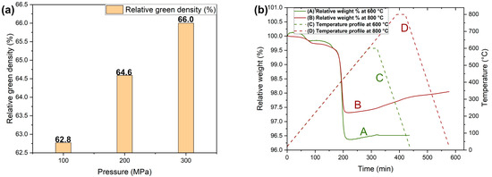
Figure 3.
Relative green density of V4E after compaction at different CIP pressures of 100 MPa, 200 MPa, and 300 MPa (a). Debinding curves for V4E showing relative weight as a function of time for two different final debinding temperatures (b).
The CIP-processed samples were then subjected to the debinding process to remove the binder either by degradation and/or evaporation at specific temperature ranges. Figure 3b illustrates the thermal debinding characteristics in argon at temperatures of 600 °C and 800 °C, respectively. In Figure 3b, curves B and A demonstrate that debinding at the higher temperature of 800 °C results in higher residual weight than debinding at 600 °C. This effect is suggested to be a result of the increased degree of oxidation. Even if debinding is done in argon, oxidation is inherent when debinding is carried out at elevated temperatures, enabling the chemical interaction between the material and the finite amount of oxygen present in the atmosphere [33]. The curve A, representing debinding at 600 °C, shows that the weight remained relatively constant with time at this temperature, indicating neither further oxidation nor degradation profile of any binder constituent, thus resulting in a nominally complete removal of the binder from the sample.
3.2. Influence of Sintering Temperature on Densification
Sintering studies were carried out with the V4E samples CIP-processed at 300 MPa and de-bound at 600 °C. Figure 4 illustrates the open and closed porosities after debinding in argon and subsequent sintering in pure nitrogen at 1150 °C and 1200 °C, respectively. It is clear that with the increase in sintering temperature, the porosity of the tool steel samples reduces significantly. The density values obtained after sintering at the temperatures of 1150 °C and 1200 °C are 7.18 ± 0.17 g/cm3 and 7.80 ± 0.01 g/cm3, respectively. After sintering at 1150 °C, there remains an open porosity of 1.73 ± 0.31%, contributing to the total porosity of 8.01 ± 2.17%. The high density obtained for the samples after sintering at 1200 °C signifies a substantial decrease in both open and closed porosity, resulting in almost full densification. Improvement in densification with increases in temperature could be attributed to liquid phase sintering involving grain-shape accommodation and dissolution-precipitation mechanism, as also reported in previous studies [12,34] and will be further discussed and addressed below.
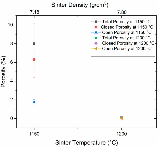
Figure 4.
Open and closed porosity of V4E samples after sintering at 1150 °C and 1200 °C, measured using the Archimedes density method.
Figure 5 displays the corresponding optical micrographs of an unetched cross-section of samples after sintering at temperatures of 1150 °C and 1200 °C, respectively. As can be seen in Figure 5a, a significant amount of porosity is evident after sintering at 1150 °C, when compared to the samples sintered at temperatures of 1200 °C, as observed in Figure 5b. This agrees with the density measurements by the Archimedes method displayed in Figure 4 above. Figure 5, hence, validates the sinter density measurements of these samples after sintering at 1150 °C and 1200 °C. Table 2 compares the porosity measures depicted from the Archimedes method and ImageJ analysis of metallographic cross-sections. The density values of the sample sintered at 1150 °C exhibited a difference of approximately 4% between the two density measurement methods. This difference arises from the fact that the metallographic characterization is a 2D assessment, while the Archimedes method represents the 3D assessment, depicting interconnected open porosity in a better way. The Image J analysis, hence, considers images from mainly the bulk region of the samples, while the influence of the open pores is distinctly noticeable for the Archimedes density measurement method. In Table 2, the relative density of the material is the same with both methods and nominally near zero porosity for material sintered at 1200 °C. In Figure 5b, precipitates are clearly visible after sintering at 1200 °C due to their increase in size (even if the sample is still not etched).
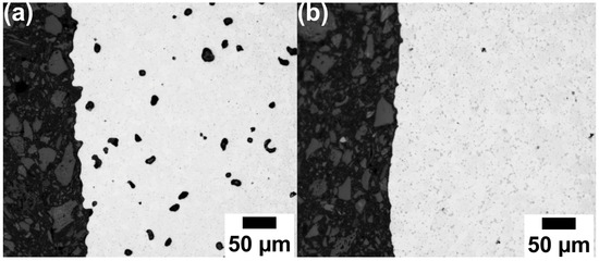
Figure 5.
Optical micrographs of V4E material sintered at 1150 °C (a) and 1200 °C (b).
Table 2.
Density measurements of V4E material sintered at 1150 °C and 1200 °C.
3.3. Influence of Post-Sintering Thermal Treatments
Figure 6 shows the unetched microstructural cross-sections of samples sintered at 1150 °C and 1200 °C, subjected to subsequent capsule-free HIP, hardening, and tempering. Characteristically, almost no pores were observed for both samples after the subsequent capsule-free HIP, hardening, and tempering (see Figure 6a,b). Compared to the appearance for the sample priorly sintered at 1150 °C (Figure 6a), Figure 6b demonstrates a smoother surface for the sample priorly sintered at 1200 °C, confirming an adequate sintering process as already seen from Figure 5b.
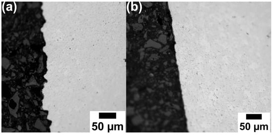
Figure 6.
Optical micrographs of V4E material after sintering at (a) 1150 °C and (b) 1200 °C, followed by capsule-free HIP, hardening, and tempering, adapted from Ref. [26].
Table 3 compares the density measurements of the samples after sintering and after subsequent capsule-free HIP, hardening, and tempering. The density for samples sintered at 1150 °C after the subsequent thermal treatments increased by 8% to 7.80 ± 0.01 g/cm3. It is expected that the capsule-free HIP is the main cause of this densification. In the case of the samples sintered at 1200 °C, the impact of capsule-free HIP is minimal, as near full density has already been achieved during the sintering.
Table 3.
Archimedes density measurements of samples after sintering at 1150 °C and 1200 °C, as well as after following capsule-free HIP, hardening, and tempering.
3.4. Microstructures and Properties
The SEM micrographs in Figure 7 reveal the microstructure of the V4E tool steel after sintering at 1150 °C and 1200 °C as well as after following capsule-free HIP, hardening, and tempering. The presence of vanadium-rich carbonitrides and molybdenum-rich carbides have been identified, consistent with observations from previous studies [21]. As the sintering temperature increases, there is a noticeable increase in grain size and the size of precipitates, particularly the dark-appearing ones, i.e., the vanadium carbonitrides (c.f. Figure 7a,b). During sintering in a nitrogen atmosphere, nitrogen dissolves into the material. The nitrogen absorption is preferentially accommodated by the transformation of VC to V(C,N) and the eventual progress to VN. Reaching VN requires, however, higher nitrogen activity than what is applied in this study. The V(C,N) is hereafter also referred to as MX as being vanadium-rich and nitrogen-rich carbonitride precipitates. As a consequence of the selective uptake of nitrogen into the MX, carbon is released into the austenite matrix and through liquid phase, the latter leading to emerge carbide in locations where liquid phase is formed. As will be discussed further later, it is supposed that the sintering in nitrogen could help reduce the solidus temperature, thereby resulting in better sintering control and enhanced densification. Figure 7d shows the distribution of the precipitates after thermal treatments of capsule-free HIP, hardening, and tempering. It can be seen that the presumed MX precipitates remain in the microstructure, and secondary carbides are also formed.
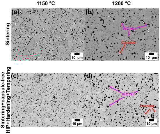
Figure 7.
SEM micrographs of V4E samples after sintering at (a) 1150 °C, and (b) 1200 °C, and (c,d) after subsequent capsule-free HIP at 1140 °C, hardening, and tempering.
Precipitates containing vanadium and molybdenum are depicted in sintered samples using EDS mapping, as shown in Figure 8. From the figure, it can be seen that vanadium is present in the presumed MX precipitates while Mo and Cr are contained in the presumed carbide precipitates. It appears that MX precipitates shown by the vanadium mapping occur in two different sizes, with larger ones decorating the grain boundaries and smaller ones indicated inside the grains. For the carbide precipitates, they tend to occur predominantly at the grain boundaries.
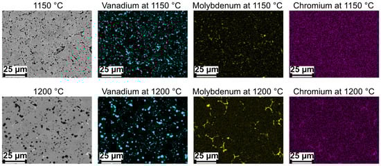
Figure 8.
SEM images and EDS mapping of V4E material after sintering at (top row) 1150 °C and (bottom row) 1200 °C.
Figure 9 presents the EDS maps of V4E material after sintering at 1200 °C. The maps clearly revealed the presence of carbon and nitrogen within MX precipitates, indicating the formation of vanadium-rich carbonitrides.
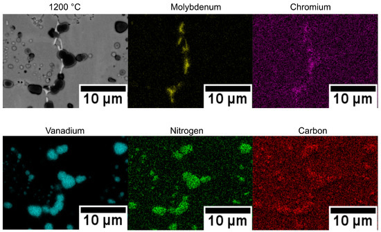
Figure 9.
SEM images and EDS mapping of V4E material after sintering at 1200 °C.
The X-ray diffraction analysis and EBSD mappings of V4E steel samples on all as-sintered conditions as well as on sintered samples, followed by capsule-free HIP, hardening, and tempering, were performed. Austenite is prevalent in all the samples; hence, for the representation of the phases in the final condition, the XRD pattern and EBSD mapping of the sample sintered at 1200 °C, followed by capsule-free HIP, hardening, and tempering, are depicted in Figure 10. The highest peak for the austenite existed at a 2θ position of 43.2°. The presence of phases such as austenite, tempered martensite, and V(C,N) is detected by both the XRD and EBSD characterisations. Here, tempered martensite is shown as BCC in the XRD plot as it is not possible to distinguish between BCC and highly tempered martensite in the diffractograms. It can be seen that a significant portion of austenite is present even after tempering, while regions of tempered martensite are occurring as expected. A previous study on cold work tool steel with high chromium content demonstrated that sintering in nitrogen atmosphere stabilized the austenite phase [35], and it also appears to be the case here. Furthermore, in accordance with Figure 7 and Figure 8, the presence of V(C,N) is confirmed.
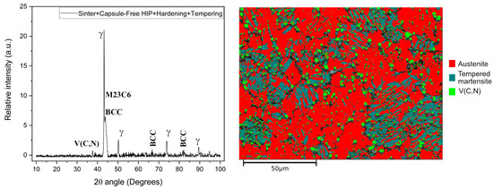
Figure 10.
X-ray Diffraction pattern (left) and EBSD mapping (right) of V4E material after sintering at 1200 °C, followed by capsule-free HIP, hardening, and tempering.
The apparent hardness values were determined for samples after sintering as well as after subsequent capsule-free HIP, hardening, and tempering. This is done to correlate with the pore characteristics and precipitates formed. The hardness values are shown in Table 4. The hardness of the samples sintered at 1150 °C is 335 ± 7 HV10 and that of samples at 1200 °C is 444 ± 14 HV10. Largely, as also reported elsewhere [10], this difference is proposed to be a result of the lower density of the former, as evident from Figure 5 and Table 2.
Table 4.
Apparent hardness measurements of samples after sintering at 1150 °C and 1200 °C, and after following capsule-free HIP, hardening, and tempering.
After subsequent processing, the hardness value increased significantly for the samples priorly sintered at temperatures of 1150 °C, while it only increased slightly for samples priorly sintered at 1200 °C. It is observed that the hardness values of 519 ± 14 HV10 and 457 ± 11 HV10 are obtained in the former and latter cases, respectively. As both these conditions are expected to represent fully dense materials, the hardness values represent the impact of different microstructures. From Figure 7, the MX precipitates formed during sintering remain coarser for material sintered at 1200 °C compared to material sintered at 1150 °C, irrespective of subsequent processing. The overall finer precipitates in the latter case are a plausible cause of the high hardness applying sintering at 1150 °C instead of 1200 °C along the processing route.
The results summarize that it can be presumed that pores were largely eliminated when sintering was carried out at 1200 °C, as seen in Figure 5, leading to near full densification, which allowed capsule-free HIP to easily bring the material to nominal full density. Still, as shown in Figure 6, even material sintered at 1150 °C to density level enough to exhibit predominantly close porosity, whereby nominally full densification was achieved as well by subsequent capsule-free HIP. In both cases, final hardening and tempering can then be tuned depending on needs.
4. Discussion
It is clear from the results presented that there is a processing route that can bring powder metallurgical tool steel to full density with potential component shaping capabilities, starting from granulated gas-atomized powder via cold isostatic pressing and sintering to closed or nearly full density, finalized with capsule-free hot isostatic pressing. A key element in the processing chain is sintering. This section provides in detail a review of the sintering by considering experimental modelling by dilatometer studies and thermodynamics-based theoretical modelling of phase equilibria and possible phase transformations.
Let us first consider the effect of the high-temperature sintering in nitrogen on densification. From the dilatometer curves in Figure 11, sintering behaviour up to 1150 °C is basically constant. Consequently, sintering at 1150 °C means a slower rate of densification, as noticed in the figure, while increasing the sintering temperature to 1200 °C significantly enhances the densification rate, whereby near full density is achieved, implying possible conformity to the sintering by liquid-phase assisted mechanism [34].
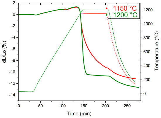
Figure 11.
Dilatometry curves of V4E PM tool steel material at sintering temperatures of 1150 °C and 1200 °C.
The formation of the liquid phase for V4E composition in Table 1 is noted at an onset temperature of 1222 °C by DSC experiments, as can be seen in Figure 12a, with a solidus and liquid temperature gap of about 178 °C. This agrees reasonably with thermodynamic simulations performed using Thermo-Calc software with TCFE13 database, as depicted in Figure 12b, which predict solidus and liquidus temperatures of 1242 °C and 1387 °C, respectively. In Figure 12a, the fluctuations observed in the DSC curve above onset of melting are supposed to be assigned to the progressive dissolution of MC precipitates expected to be complete before reaching the liquidus temperature. When pre-alloyed powder is sintered above its solidus temperature, the densification is achieved on reaching a certain threshold of partial melting [36], as shown by Liu and German. This resulting early-stage densification in liquid phase sintering mechanism could be due to the disintegration of grain/particles into fragments and the subsequent repacking of these fragments [37]. Higher carbon content means that the solidus temperature decreases [38]. As a matter of fact, the V4E PM tool steel alloy is very sensitive to the carbon level for the onset of liquid phase. Also, from analysis of de-bound samples, it is found that the carbon level may reach up to 1.5 wt.% to 1.6 wt.% prior to sintering. Consequently, as the slightly added carbon should be located at powder surfaces, it is suggested that this triggers local enrichment of liquid phase in early stages of the sintering, which presumably adds a transient liquid phase sintering effect subject to the initial impact of nitrogen, as outlined further below.
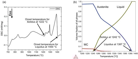
Figure 12.
(a) DSC signal vs. temperature for V4E PM tool steel sample (b) Thermodynamic simulation of V4E using ThermoCalc software (2024a Version).
The question then arises: What happens with V4E when sintered in a nitrogen atmosphere? The first issue is to understand the impact of nitrogen activity on nitrogen uptake and then where and how nitrogen is captured in the material. Figure 13a shows a pseudo-binary phase diagram for V4E composition plus nitrogen predicted by Thermo-Calc simulations. The figure illustrates the possible nitrogen uptake in wt.% (y-axis) into the material when sintering in nitrogen atmosphere at different pressures of 0.5 bar, 1 bar, and 1.5 bar. It depicts the occurrence of nitrogen pickup with an increase in the nitrogen activity in the material, leading to the formation of an increased amount of carbonitride at all pressures. This nitrogen activity is the nitrogen dissolved in the austenitic matrix. A similar approach is studied by Farayibi and Blüm [35], who noted the nitrogen pickup in samples as the nitrogen pressure increased when sintered at 1100 °C. In this study, as indicated in the figure, sintering at a temperature of 1200 °C and a pressure of 1.5 bar (right dotted line) is supposed to trigger the formation of liquid phase and lead to a nitrogen content of 0.85 wt.% in the sample, potentially leading to rapid densification. Previous studies explain that sintering in the presence of nitrogen not only reduces solidus temperature compared to sintering in vacuum conditions, but also transforms MC to MX [21,39]. This will be discussed later on in connection with Figure 14.
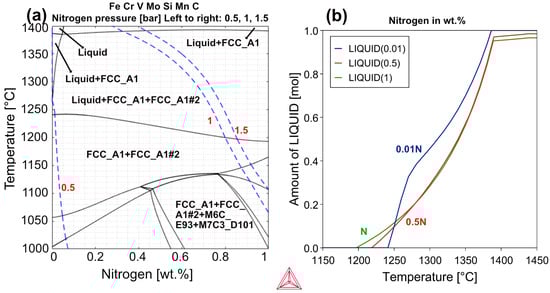
Figure 13.
Thermodynamic calculations studies of V4E PM tool steel (a) at different pressures of nitrogen (b), with varying amounts of N in the sample.
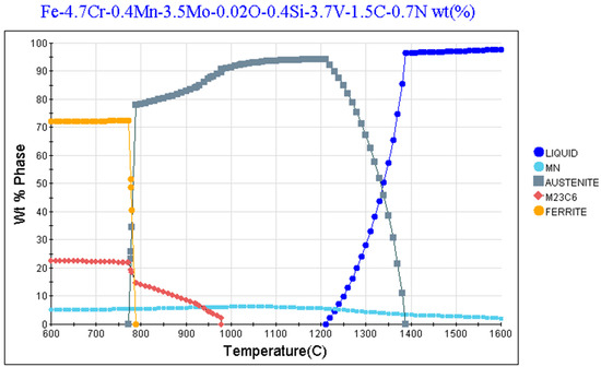
Figure 14.
JMatPro simulation (Version 12.4) of V4E PM cold work tool steel with 0.7% nitrogen.
Figure 13b shows the thermodynamic simulations performed using ThermoCalC software (Version 2024a) for the V4E PM tool steel with varying nitrogen content in the material (plots). With the uptake of nitrogen in the sample from almost no nitrogen (0.01 wt.%) to 1 wt.%, the solidus temperature is supposed to reduce from 1242 °C to slightly under 1200 °C. It has been observed in previous studies that sintering of tool steels containing carbon in nitrogen atmosphere can lead to improved densification [40], as observed in Figure 5. This density enhancement is attributed to two factors: one of which is carbothermal reactions that reduce surface oxides, thus accelerating sintering activity between the particles, and the other is due to liquid phase sintering (LPS) mechanism. Additionally, sintering in nitrogen results in lower solidus temperature, together with an expanded solidification range [21,41].
Previous studies [42,43] have demonstrated that after conventional heat treatment of powder metallurgical V4E cold work tool steel, having carbide forming alloying elements such as V, Cr, Mo, the precipitates MC, M2C, and M7C3 occur in its microstructure. In this study, during sintering in nitrogen atmosphere of the V4E tool steel, the MC transforms to M(C,N). Figure 14 shows the JMatPro prediction of equilibrium phases and their content as a function of temperature for V4E composition plus 0.7 wt.% nitrogen. The calculations suggest that only MX (denoted as MN but having both C and N, according to phase composition prediction) can exist at temperatures above around 1200 °C besides austenite and liquid phase. What is also evident from Figure 14 is that the MN (i.e., MX) is kept at about the same concentration downwards in temperature. Consequently, once the MX is formed during the sintering, it will keep the nitrogen. In fact, the JMatPro calculations predict that the nitrogen level in the austenite for 0.7 wt% N is about 0.03 wt.%. Thus, no nitrogen activity takes place to transform V(C,N) to VN. Hence now, in the sintered conditions, Mo-rich carbides, presumably M2C, are present. These should not be formed at homogeneous and equilibrium conditions. It is suggested that their presence is due to the heterogeneous state of liquation (transient liquid phase sintering), c.f. Figure 7. Upon further thermal treatments from capsule-free HIP to hardening and tempering, the stable MX remains unaffected, while the M2C, being unstable above 1000 °C, is dissolved during the HIP processing and then is not present anymore after any further heat treatment, c.f. Figure 7 and Figure 8. After tempering, secondary carbide M23C6 will instead occur, c.f. Figure 7, Figure 8, Figure 10 and Figure 14. The source of increased carbon for carbide formation is the transformation of the MC to MX. The carbon for this comes from the expel of carbon to austenite during sintering. The capsule-free HIP is done with rapid cooling facility. Normally, it is expected that martensite is formed to a larger extent on rapid cooling of austenite from elevated temperature [44]. In contrast to these studies, austenite is predominant, as seen in Figure 10, after the thermal treatments involving capsule-free HIP and hardening, followed by tempering at 525 °C three times. In this study, it is supposed that none to a very little amount of martensite is formed during either cooling during the capsule-free HIP or hardening before the final tempering treatment. Figure 15 shows the predicted martensitic transition temperature of V4E PM tool steel with and without nitrogen content in the material with initial austenitization temperature as input. The austenitization temperature determines the amount of carbon in the austenite, and hence, indirectly also the temperature of onset of martensite formation. Now, hardening with austenitization at 1100 °C means, as seen in Figure 15a, Ms = 167 °C without nitrogen and Ms = 23 °C with nitrogen. Also, considering cooling from either 1150 °C or 1200 °C would mean that Ms is pushed downwards as well for the material in question. Clearly, for the final hardening process, the formation of martensite is limited. Still, tempered martensite appears after the three sequential tempering runs. This can be related to the progressive formation of carbides with a decline of the carbon level in austenite, which increases the Ms, whereby a portion of the microstructure becomes tempered martensite, while a significant amount remains as austenite.
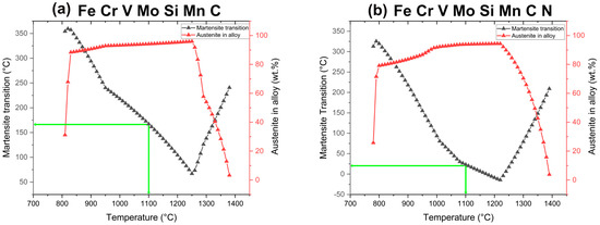
Figure 15.
Martensite transition of V4E cold work tool steel with and without nitrogen predicted by JMatPro simulation (Version 12.4) for hardening temperature of 1100 °C (green line).
During sintering, carbon can act as a reducing agent, which needs to be considered as well. It is also important to depict to what extent nitrogen level introduced is maintained during subsequent processing after sintering. Table 5 presents the chemical analyses for carbon, oxygen, and nitrogen after sintering and after subsequent capsule-free HIP, hardening, and tempering. Carbon level remains almost the same after sintering at 1150 °C and 1200 °C. This is also the case after the post-sintering treatments. As can be seen, oxygen has been reduced to a very low level after sintering and so to even more for the highest temperature. This reduction is due to the carbothermal reactions leading to basically complete oxide removal, as presented in other studies for sintering of tool steel [45,46]. Regarding nitrogen, the nitrogen level is slightly higher after sintering at 1150 °C than after sintering at 1200 °C. This agrees well with Figure 12a; as the sintering temperature increases at the nitrogen pressure of 1.5 bar, nitrogen content should reduce, as represented by the blue dotted line on the right side. This trend agrees with the observed trend of measured values in Table 5. Notably, the carbothermal reduction could be enhanced by residual carbon from the binder. Also, residual carbon from the binder is a trigger for enhanced liquid-phase formation when sintering at 1200 °C. Also, the solidus temperature of V4E plus added nitrogen is very sensitive to carbon level; for example, going from 1.4 wt.% to 1.6 wt.% shifts the solidus down with about 30 °C. Compared with the samples in sintered condition, the subsequent capsule-free HIP, hardening, and tempering appears to reduce the oxygen values further, arriving at such low oxygen levels as 0.001 wt.%. Overall, this indicates that these processes are maintained with very good atmospheric control, and residual oxygen levels required for high-performance applications are attainable. These values depict the complete removal of oxides present in the samples.
Table 5.
Chemical analysis of V4E samples after sintering at 1150 °C and 1200 °C, and after sintering followed by capsule-free HIP at 1140 °C, hardening, and tempering. All concentrations are given in wt.%.
5. Conclusions
In this study, a novel processing route to create fully dense powder metallurgical V4E tool streel is developed. The processing route involves the initial granulation of the gas-atomized powder to allow for the compaction by means of cold isostatic pressing at 300 MPa to create green parts for sintering. The inherent ability of the V4E tool steel to be sintered to high relative density is then taken advantage of by applying nitrogen atmosphere sintering. When sintering at either 1150 °C or 1200 °C, nitrogen absorption of up to around 0.7 wt.% is obtained. For the lower temperature, sintering to predominantly closed porosity is obtained, while the higher temperature leads to near full density, presumed to be a result of liquid phase-assisted sintering. In either case, capsule-free hot isostatic pressing was then possible to create nominally full density. The concrete observations can be summarized as follows:
- Density values of 7.80 ± 0.01 g/cm3 were obtained for sample sintered at 1150 °C, and followed by capsule-free HIP, hardening, and tempering. Similarly, density values of 7.81 ± 0.01 g/cm3 were achieved already after sintering at 1200 °C prior to thermal treatments.
- Microstructures revealed by means of SEM showed the distribution of coarse vanadium-rich nitrides/carbonitrides decorating the grains and the finer ones inside the grains, together with molybdenum-rich carbides at the grain boundaries after sintering.
- The EDS mapping of sintered samples showed that the precipitates with vanadium and molybdenum increased in size with increasing sintering temperature.
- The EBSD mapping revealed that austenite phase is prevalent in all the samples (representatively shown on the sample sintered at 1200 °C) after sintering as well as after subsequent capsule-free HIP, hardening, and tempering. The XRD patterns for as-tempered conditions depicted austenite, vanadium-rich nitrides/carbonitrides, and tempered martensite.
- The austenite phase is stabilized as a result of the higher carbon content in the matrix after sintering, owing to the transformation of MC to MX with associated expel of carbon. This means that the martensite start temperature is pushed to low temperatures. For austenitization at 1100 °C, simulations predict it to be 23 °C. Consequently, a high amount of stabilized austenite is observed after tempering, together with the presence of tempered martensite, the latter being formed during the subsequent tempering runs.
- Apparent hardness values were higher for final fully densified as-tempered samples with initial sintering at 1150 °C compared to initial sintering at 1200 °C. The values measured were 519 ± 14 HV10 and 457 ± 11 HV10, respectively. The higher apparent hardness value in the former case is attributed to finer distribution of secondary phase precipitates.
Author Contributions
Conceptualization, A.B.N., G.M. and L.N.; methodology, A.B.N., G.M. and E.A.; software, A.B.N.; validation, A.B.N., L.N. and Y.C.; investigation, A.B.N.; resources, G.M., E.A., E.H. and L.N.; writing—original draft preparation, A.B.N.; writing—review and editing, G.M., Y.C. and L.N.; supervision, L.N. and E.H. All authors have read and agreed to the published version of the manuscript.
Funding
This study is performed within the project DENSE (contract no. 2018-02371) within the Strategic Innovation programme with support from Vinnova, FORMAS, and the Swedish Energy Agency. Technical support from Uddeholms AB and support from the LIGHTer Academy project (contract no. 2020-04526) within the LIGHTer Strategic Innovation Programme with support from Vinnova, FORMAS, Swedish Energy Agency, as well as the Production Area of Advance at Chalmers, are acknowledged.
Data Availability Statement
The raw data supporting the conclusions of this article will be made available by the authors on request.
Acknowledgments
Special thanks to Lars Ekman from Uddeholms AB for assistance in thermal treatments.
Conflicts of Interest
Author Giulio Maistro was employed by the company Uddeholms AB, Sweden and author Erik Adolfsson was employed by the company RISE IVF AB, Sweden. The remaining authors declare that the research was conducted in the absence of any commercial or financial relationships that could be construed as a potential conflict of interest. The authors declare that this study received funding from Vinnova, FORMAS, and the Swedish Energy Agency. The funder was not involved in the study design, collection, analysis, interpretation of data, the writing of this article or the decision to submit it for publication.
References
- Muhammed, M.; Javidani, M.; Heidari, M.; Jahazi, M. Enhancing the Tribological Performance of Tool Steels for Wood-Processing Applications: A Comprehensive Review. Metals 2023, 13, 1460. [Google Scholar] [CrossRef]
- Podgornik, B.; Sedlaček, M.; Žužek, B.; Guštin, A. Properties of tool steels and their importance when used in a coated system. Coatings 2020, 10, 265. [Google Scholar] [CrossRef]
- Elghazaly, S.A. Innovations in Cold Work Tool Steels-Research and Development. Int. J. Mater. Technol. Innov. 2023, 3, 64–73. [Google Scholar] [CrossRef]
- Rosso, M.; Ugues, D.; Grande, M.A. The challenge of PM tool steels for the innovation. J. Achiev. Mater. Manuf. Eng. 2006, 18, 175–178. [Google Scholar]
- Klobčar, D.; Tušek, J.; Taljat, B. Thermal fatigue of materials for die-casting tooling. Mater. Sci. Eng. A 2008, 472, 198–207. [Google Scholar] [CrossRef]
- Chang, S.-H.; Tang, T.-P.; Huang, K.-T.; Tai, F.-C. Effects of sintering process and heat treatments on microstructures and mechanical properties of VANADIS 4 tool steel added with TiC powders. Powder Metall. 2011, 54, 507–512. [Google Scholar] [CrossRef]
- Huang, K.-T.; Chang, S.-H.; Yeh, P.-T. Microstructures and mechanical properties of TaC added to vanadis 4 tool steel through vacuum sintering and heat treatments. ISIJ Int. 2017, 57, 1252–1260. [Google Scholar] [CrossRef]
- Samtaş, G.; Korucu, S. The effect and optimization of cutting parameters of Vanadis 4E powder metallurgical tool steel on tool wear: Surface roughness in face milling. Sadhana-Acad. Proc. Eng. Sci. 2022, 47, 135. [Google Scholar] [CrossRef]
- Korucu, S. The effects of sharpened tools on tool flank wear–surface roughness and optimization of cutting parameters in milling Vanadis 4E powder metallurgic tool steel. Sadhana-Acad. Proc. Eng. Sci. 2020, 45, 137. [Google Scholar] [CrossRef]
- Nagaram, A.B.; Sundaram, M.V.; Gårdstam, J.; Andersson, M.; Chen, Z.; Hryha, E.; Nyborg, L. Consolidation of water-atomized chromium–nickel-alloyed powder metallurgy steel through novel processing routes. Powder Metall. 2024, 67, 6–17. [Google Scholar] [CrossRef]
- Haynes, R. Development of sintered low alloy steels. Powder Metall. 1989, 32, 140–146. [Google Scholar] [CrossRef]
- Tojal, C.; Gómez-Acebo, T.; Castro, F. Development of PM Stainless Steels with Improved Properties through Liquid Phase Sintering. Mater. Sci. Forum 2007, 534–536, 661–664. [Google Scholar] [CrossRef]
- Hanejko, F.; Rawlings, A.; King, P.; Poszmik, G. Surface Densification Coupled with Higher Density Processes Targeting High-Performance Gearing. Mater. Sci. Forum 2007, 534–536, 317–320. [Google Scholar] [CrossRef]
- Sundaram, M.V. Novel Approaches for Acheiving Full Density Powder Metallurgy Steels. Ph.D. Thesis, Chalmers University of Technology, Gothenburg, Sweden, 2019. [Google Scholar]
- Giménez, S.; Iturriza, I. Study of the Sintering Behaviour of Pm Hss Under Nitrogen Atmospheres: Application To Alloy Design. In Proceedings of the EuropPM 2003 High Alloy Steels, Valencia, Spain, 20–22 October 2003. [Google Scholar]
- Konoplev, A.M.; Titenskaya, G.É. Reduction annealing of a water-atomized high-speed steel powder. Poroshkovaya Metall. 1988, 10, 11–14. [Google Scholar] [CrossRef]
- Wu, M.W.; Hwang, K.S. Improved homogenization of Ni in sintered steels through the use of Cr-containing prealloyed powders. Metall. Mater. Trans. A Phys. Metall. Mater. Sci. 2006, 37, 3577–3585. [Google Scholar] [CrossRef]
- Kim, K.; Cho, J. A densification model for mixed metal powder under cold compaction. Int. J. Mech. Sci. 2001, 43, 2929–2946. [Google Scholar] [CrossRef]
- Pavlíčková, M.; Vojtěch, D.; Novák, P.; Gemperlová, J.; Gemperle, A.; Zárubová, N.; Lejček, P.; Jurči, P.; Stolař, P. Thermal treatment of PM-tool steel alloyed with niobium. Mater. Sci. Eng. A 2003, 356, 200–207. [Google Scholar] [CrossRef]
- Wright, C.; Wronski, A.; Iturriza, I. Overview: Development of robust processing routes for powder metallurgy high speed steels. Mater. Sci. Technol. 2000, 16, 945–957. [Google Scholar] [CrossRef]
- Borgström, H.; Nyborg, L. Liquid Phase Sintering of Ferrous Powder Metallurgical Materials. J. Iron Steel Res. Int. 2007, 14, 70–76. [Google Scholar] [CrossRef]
- Hatami, S.; Nafari, A.; Nyborg, L.; Jelvestam, U. Galling related surface properties of powder metallurgical tool steels alloyed with and without nitrogen. Wear 2010, 269, 229–240. [Google Scholar] [CrossRef]
- Sun, H.; Yang, F.; Qin, Q.; Zhang, B.; Volinsky, A.A.; Guo, Z. In-situ VN reinforced powder metallurgy M30 steels prepared from water atomized powers via pressureless sintering. Powder Metall. 2020, 63, 43–53. [Google Scholar] [CrossRef]
- Wang, H.-J.; Feng, H.; Li, H.-B.; Zhou, G.; Zhu, H.-C.; Zhang, S.-C.; Jiang, Z.-H. Nitrogen-Substituting Carbon Significantly Improves Softening Resistance of H13 Hot-Work Die Steel. Metall. Mater. Trans. A 2024, 55, 1916–1931. [Google Scholar] [CrossRef]
- Gromov, V.E.; Ivanov, Y.F.; Potekaev, A.I.; Guseva, T.P.; Yuriev, A.B.; Chapaikin, A.S. Effect of Tempering on Structure and Properties of Plasma Surfacing of R2M9U High-Speed Tool Steel. Russ. Phys. J. 2024, 67, 259–266. [Google Scholar] [CrossRef]
- Nagaram, A.B. Net-Shape Consolidation of Water-Atomised and Gas-Atomised Steel Powder towards Full Density. Licentiate Thesis, Chalmers University of Technology, Gothenburg, Sweden, 2022. [Google Scholar]
- Andersson, J.-O.; Helander, T.; Höglund, L.; Shi, P.; Sundman, B. Thermo-Calc & DICTRA, computational tools for materials science. CALPHAD 2002, 26, 273–312. [Google Scholar] [CrossRef]
- ASTM B238-96; Standard Test Method for Density, Oil Content, and Interconnected Porosity of Meal Structural Parts and Oil-Impregnated Bearings. ASTM International: West Conshohocken, PA, USA, 2003; pp. 1–4.
- Schindelin, J.; Arganda-Carreras, I.; Frise, E.; Kaynig, V.; Longair, M.; Pietzsch, T.; Preibisch, S.; Rueden, C.; Saalfeld, S.; Schmid, B.; et al. Fiji: An open-source platform for biological-image analysis. Nat. Methods 2012, 9, 676–682. [Google Scholar] [CrossRef] [PubMed]
- ASTM E-384-17; Standard Test Method for Microintdentation Hardness of Matrials. ASTM International: West Conshohocken, PA, USA, 2017; pp. 4–6.
- German, R.M. Particle Packing Characteristics; Metal Powder Industries Federation: Princeton, NJ, USA, 1989. [Google Scholar]
- James, P.J. Particle deformation during cold isostatic pressing of metal powders. Powder Metall. 1977, 20, 199–204. [Google Scholar] [CrossRef]
- Roumanie, M.; Flassayer, C.; Resch, A.; Cortella, L.; Laucournet, R. Influence of debinding and sintering conditions on the composition and thermal conductivity of copper parts printed from highly loaded photocurable formulations. SN Appl. Sci. 2021, 3, 55. [Google Scholar] [CrossRef]
- Sundaram, M.V.; Surreddi, K.B.; Hryha, E.; Veiga, A.; Berg, S.; Castro, F.; Nyborg, L. Enhanced Densification of PM Steels by Liquid Phase Sintering with Boron-Containing Master Alloy. Metall. Mater. Trans. A 2018, 49, 255–263. [Google Scholar] [CrossRef]
- Farayibi, P.; Blüm, M.; Weber, S. Densification of a high chromium cold work tool steel powder in different atmospheres by SLPS: Microstructure, heat treatment and micromechanical properties. Mater. Sci. Eng. A 2019, 777, 139053. [Google Scholar] [CrossRef]
- German, R.M. Supersolidus liquid-phase sintering of prealloyed powders. Metall. Mater. Trans. A 1997, 28, 1553–1567. [Google Scholar] [CrossRef]
- Liu, Y.; Tandon, R.; German, R.M. Modeling of supersolidus liquid phase sintering: II. Densification. Metall. Mater. Trans. A 1995, 26, 2423–2430. [Google Scholar] [CrossRef]
- Nandwana, P.; Kannan, R.; Siddel, D. Microstructure evolution during binder jet additive manufacturing of H13 tool steel. Addit. Manuf. 2020, 36, 101534. [Google Scholar] [CrossRef]
- Myers, N.S.; Heaney, D.F. Metal Injection Molding (MIM) of High-Speed Tool Steels, 2nd ed.; No. MIM; Elsevier Ltd.: Amsterdam, The Netherlands, 2019. [Google Scholar] [CrossRef]
- Bolton, J.D.; Gant, A.J.; Hague, R.J.M. Liquid-phase sintering of high-speed steels. J. Mater. Sci. 1991, 26, 5203–5211. [Google Scholar] [CrossRef]
- Wright, C.S.; Ogel, B. Supersolidus sintering of high speed steels: Part 1: Sintering of molybdenum based alloys. Powder Metall. 1993, 36, 213–219. [Google Scholar] [CrossRef]
- Arslan, F.; Altinsoy, I.; Hatman, A.; Ipek, M.; Zeytin, S.; Bindal, C. Characterization of cryogenic heat treated Vanadis 4 PM cold work tool steel. Vacuum 2011, 86, 370–373. [Google Scholar] [CrossRef]
- Kim, H.; Kang, J.-Y.; Son, D.; Lee, T.-H.; Cho, K.-M. Evolution of carbides in cold-work tool steels. Mater. Charact. 2015, 107, 376–385. [Google Scholar] [CrossRef]
- Uddeholms, A.B. Heat Treatment of Tool Steel; Uddeholms AB: Hagfors, Sweden, 2012; Volume 8, pp. 1–20. [Google Scholar]
- Hryha, E.; Nyborg, L. Effectiveness of reducing agents during sintering of Cr-prealloyed PM steels. Powder Metall. 2014, 57, 245–250. [Google Scholar] [CrossRef]
- Hryha, E.; Nyborg, L. Thermogravimetry study of the effectiveness of different reducing agents during sintering of Cr-prealloyed PM steels. J. Therm. Anal. Calorim. 2014, 118, 825–834. [Google Scholar] [CrossRef]
Disclaimer/Publisher’s Note: The statements, opinions and data contained in all publications are solely those of the individual author(s) and contributor(s) and not of MDPI and/or the editor(s). MDPI and/or the editor(s) disclaim responsibility for any injury to people or property resulting from any ideas, methods, instructions or products referred to in the content. |
© 2024 by the authors. Licensee MDPI, Basel, Switzerland. This article is an open access article distributed under the terms and conditions of the Creative Commons Attribution (CC BY) license (https://creativecommons.org/licenses/by/4.0/).