Article

Influence of High-Temperature Aggressive Environments on the Durability of Composites Reinforced with Refractory Particles

by
Peter Rusinov
*,
George Kurapov
,
Anastasia Rusinova
,
Maxim Semadeni
and
Polina Sereda
Department of Engineering of Control Systems, Materials and Technologies in Mechanical Engineering, Kuban State Technological University, 350072 Krasnodar, Russia
*
Author to whom correspondence should be addressed.
Metals 2024, 14(8), 939; https://doi.org/10.3390/met14080939
Submission received: 22 July 2024 / Revised: 7 August 2024 / Accepted: 15 August 2024 / Published: 16 August 2024

Abstract

:
The problem of increasing heat resistance and corrosion and erosion resistance of gas turbine units in compressor stations was solved through the development of new layered materials containing nanostructured grains. The authors carried out a destruction analysis of gas turbine units in compressor stations. It was shown that after 10–30,000 h of operation, the greatest damage occurred when the gas turbine operated in dusty environments at high temperatures (or in air environments with a high salt content). The developed layered composites include the thermal barrier and functional reinforced nanostructured layers consisting of refractory carbides and oxides. This paper describes the destruction mechanism of gas turbine units under the influence of high-temperature aggressive environments. As a result, a new formation technology for reinforced nanostructured layered composites has been developed. The developed composition makes it possible to increase the heat resistance of materials by approximately 10 times. This significantly increases the reliability and durability of gas turbine units in compressor stations. The structural and mechanical parameters of the layered nanostructured heat-resistant composites have been studied.

1. Introduction

A gas temperature increase in front of a turbine is an important problem for the design of industrial gas turbine units (GTUs). The temperature increases the risk of corrosion damage to the turbine wheel space [1,2,3,4,5]. This is why it is necessary to develop new heat-resistant materials for gas turbine units and effective methods for their surface protection from corrosion and erosion destruction. The use of cooled nozzles and turbine blades reduces the surface temperature of the material and increases the service life between overhauls. Meanwhile, the cast-cooled turbine blades can significantly increase heat resistance and durability.
During operation, gas turbine units are exposed to aggressive effects of various environments and high temperatures [6,7,8]. Additionally, gas turbine units are used in sea air, in sandy deserts, on different types of fuel, and at different levels of operating temperatures [9,10,11]. The operation of gas turbine units in countries with severe climatic conditions affects the rate and nature of turbine blades’ destruction. This can be proved by the destruction statistics of gas turbine units [12,13,14,15].
The main cause of gas turbine destruction is high-temperature sulfide–oxide corrosion. The sulfide–oxide corrosion is caused by mechanical impurities in cyclic air (high dust content of atmospheric air, high soil salinity), by a high level of operating temperatures up to 1173 K, by liquid and solid fractions of fuel natural gas, etc. [16,17,18,19].
Scientists around the world are striving to increase the service life of gas turbine units, in particular the durability of rotor blades [20,21,22,23,24,25]. Currently, the use of composite surface-modified layers [26,27,28,29] is a promising method for increasing the durability of gas turbine units operating at high temperatures in aggressive environments. The combination of materials with different functional and mechanical properties in the surface layer allows us to obtain compositions that are multifunctional, heat-resistant, and erosion- and corrosion-resistant. These materials also provide the increased reliability and service life of a gas turbine unit [30,31,32,33,34]. Currently, to increase the heat resistance of components and assemblies used in high-temperature technologies, new materials based on refractory oxides and carbides are being developed [9,20,24,32,35,36,37,38,39,40,41]. The heat-resistant alloys GTD 111, Inconel 738LC, Rene N6, etc., are mainly used for nozzle blades in industrial gas turbines. They are not effective when exposed to high-temperature sulfide–oxide corrosion.
The purpose of this work is to evaluate the influence of high-temperature aggressive environments on the durability of materials used in gas turbine units in compressor stations. The authors also aim to develop a new class of heat-resistant and corrosion- and erosion-resistant materials (surface-modified layers), in order to increase the durability of elements in gas turbine units in compressor stations.

2. Materials, Equipment, and Research Methods

The alloys GTD 111, Rene N6, and Inconel 738LC (OH, USA) were chosen as the basis. They are widely used in oil and gas and aviation industries [42,43,44,45,46]. The new alloys Alloy 1 and Alloy 2 (Krasnodar, RF) were developed as surface-modified layers (Table 1). The plasma jet (vacuum plasma spraying (VPS)) in a protective atmosphere (argon environment) was used as a source of thermal energy. The choice of thermal energy source can be explained by the possibility to form a high-quality structure due to an exceptionally short time of interaction with the treated surface. This means that it is possible to use the high rates of heating and cooling of the applied material. The formation of composites was carried out using the plasma equipment (in a protective argon environment). The optimal technological regimes for producing a composite material using the VPS method were as follows: plasma-forming gas Ar = 80% and N2 = 20%; spraying distance—150 mm; voltage—38 V; current—305 A; power—11.6 kW; and plasma-forming gas flow rate—0.483 L/s.
Before the VPS in a protective environment, a high-energy mechanical treatment (HMT) of the powder compositions was carried out. To improve the functional and mechanical properties of surface-layered compositions, the HMT was carried out in a water-cooled planetary-centrifugal ball mill, GEFEST-2 (AGO-2U) (Moscow, RF), with the following parameters: drum volume—150 cm3, ball acceleration—40 g, ball-to-load ratio—(10–15):1, ball diameter—6 mm, ball material—WC, carrier rotation speed—890 rpm, and drum rotation speed—1000 rpm. The HMT was carried out in an inert environment (argon environment). The grinding and activation of powder compositions in the AGO-2U ball mill was accomplished in the field of three inertial forces: the Coriolis force and two centrifugal forces. The centrifugal forces acting on the balls and powder are many times greater than the force of gravity. This causes a rapid activation of the powder. The VPS in a protective environment was carried out after high-energy mechanical treatment for 20–40 min.
Before the VPS, the powders were dried in a vacuum oven for 3–6 h at a temperature of 393–453 K. To increase the adhesion strength of the composite layers to the base (the GTD 111, the Rene N6, and the Inconel 738LC), the surface was preliminary sandblasted.
The microstructure was studied with a super-high-resolution scanning electron microscope, JSM-7500F, and with a transmission electron microscope, JEM-2100 (Akishima, Tokyo, Japan). The chemical composition of materials was analyzed with an Arcmet 8000 (Tokyo, Japan) optical emission analyzer of metals and alloys and with an energy-dispersive INCA x-sight attachment of a JSM-7500F (Akishima, Tokyo, Japan) electron microscope. The thickness of the composite layers was measured with a DMS 2E (GmbH, Kassel, Germany) thickness gauge. An X-ray phase analysis was carried out on a Dron-7M device. The chemical analysis of the studied powder compositions is presented in Table 1.
The microhardnesses of the composite layers were measured with a Falcon 503 (Hong Kong, China) device with a diamond pyramid with an apex angle of 136° and an indenter load of 100–300 g. The porosities of the composite layers were determined by hydrostatic weighing.
The factographic, electron microscopic, and X-ray phase analyses of the fracture surface and deep layers of materials, as well as the X-ray photoelectron spectroscopy, were used to study gas turbine units destroyed by high-temperature corrosion. Samples from a hollow nozzle blade (new ones and after 15,000 h of operation) were cut from the trough side near the inlet edge (with large thickness of the corrosion layer) and towards the outlet edge (with small thickness of the corrosion layer). At the same time, the corrosion layer, the zone of intense corrosion (the border of the section “metal-scale”), and the zone of “healthy” metal not subject to corrosion were also studied. The mechanical properties and grain size of the materials are presented in Table 2.
To study the materials (the Inconel 738LC, the GTD 111, the Rene N6, and ceramic materials) for high-temperature corrosion effects, a “synthetic material” was produced. This material was similar to deposits on the nozzle blades of the high-pressure turbine (HPT) of gas turbine units (Na2SO4—71%, NaCl—10%, Fe2O3—10%, CaO—7%, NiO and MgO—2%). Afterwards, the developed composite materials were installed into ceramic crucibles filled with “synthetic material”. The composite materials were placed in a container made of heat-resistant steel, which was placed in a vacuum oven (1223–1273 K), where it was kept for a specified time.

3. Results and Discussion

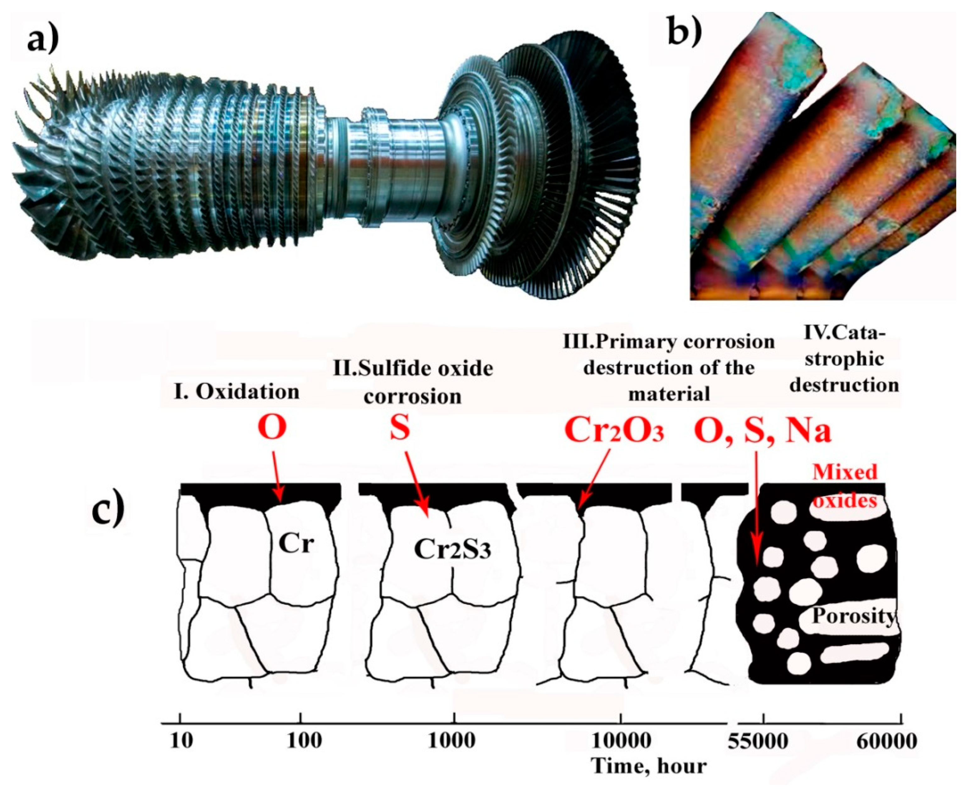
3.1. High-Temperature Corrosion of Industrial Gas Turbine Units

The reliability of industrial gas turbine units (Figure 1a) largely depends on the resistance of the metal nozzle blades to sulfide–oxide corrosion (Figure 1b), caused by sodium sulfate (Na2SO4), sodium chloride (NaCl), etc.
Industrial turbines are designed to operate for many years on heavy and poorly purified fuels, often clogged with mechanical impurities of cycle air (salt). Therefore, to achieve the designed life cycle (on average about 50,000 h), the stress and temperature levels must be lower. Resistance to sulfide–oxide corrosion is required for moderate-strength alloys.
The development of new high-temperature anti-corrosion materials has become necessary in recent years for industrial gas turbines due to the following reasons:
-
An increase in gas temperature, leading to higher corrosion rates;
-
The use of low-grade fuel, unrefined from corrosive components;
-
The need to maintain high surface quality under high gas flow.
The corrosion damage to power gas turbine blades is caused by sodium and sulfur compounds in fuel and air. Sulfide–oxide corrosion causes an intense destruction of the blades. The ash deposits, 1–2 mm thick after 1000 h of operation, contain Na sulfate. After 300–1000 h of operation in 1073–1273 K, tubercles (“warts”) or annular growths with cavities (craters) appear on the guide blades of the first stage of a gas turbine unit made of the GTD 111, the Rene N6, and the Inconel 738 LC alloys. The tubercles with diameters of 0.2–4.5 mm, when chipped, look like “ulcers” up to 0.6 mm deep, usually on the entrance edge. Over time, the numbers and sizes of the tubercles increase, and a continuous oxide crust of corrosion forms on the affected surface of the blades. The oxide crust at room temperature is brittle and destructible due to the difference in the thermal expansion coefficients of the materials. The formation of tubercles at the beginning of intense sulfide–oxide corrosion occurs due to a “breakdown” of the ash coating and the oxide film on the material. As a result, the oxygen access to the surface of the material is facilitated. The chemical analysis of the material showed that it consists of 43% Ni. The results of the X-ray spectral analysis confirmed that the corrosion mechanism in this case is a sulfide–oxide one.
The samples of the ash deposits from gas turbine blades were subjected to a chemical analysis for impurities in the fuel and components of the blade material. This analysis demonstrated that the main aggressive components are Na and sulfate sulfur. Although the temperature on the guide blades of low-pressure turbines is 330 K lower than that of the blades of high-pressure turbines, the composition of ash deposits on the blades of low- and high-pressure turbines turned out to be almost the same. The process of oxidation and corrosion damage of the nickel alloy is simplified in the form of a corrosive effect diagram for diesel combustion products containing sulfur and sea salt. These are carried along with the air (Figure 1c). At stage 1, a protective oxide film consisting predominantly of Cr2O3 is formed by means of selective oxidation. This happens due to the higher chemical affinity of chromium to oxygen, compared to sulfur. Even if the fuel contains 1–2% sulfur, its thermodynamic activity in the exhaust gas is too low for the formation of sulfides, and therefore oxides are formed. At the same time, salt, mainly Na2SO4, is deposited on the oxide film. The oxidizing atmosphere and the salt deposited on the surface of the materials enable the chemical potential of oxygen and sulfur through the oxide film. Therefore, there is a continuous growth of the film and diffusion of sulfur and oxygen into the alloy. As the oxide film grows, the underlying layers of the alloy become depleted of chromium.
At the second stage (the corrosive stage), the destruction of the protective film is accompanied by the formation of double oxides, Na2CrO4. The released sulfur diffuses through the thin film. When entering the alloy, sulfur forms dispersed particles of CrxS and causes a further depletion of the alloy in chromium. Sulfur from the H2-H2S mixture diffuses at a high speed through the dense Cr2O3 film, and from SO2 through the NiO film. Due to the fact that insufficient chromium is supplied from the alloy to maintain the oxide film of Cr2O3, we observe the formation of a loose oxide film of the spinel type or a film rich in nickel. This ensures higher oxidation rates. At the same time, the diffusion of oxygen into the depleted zone of the alloy causes internal dispersed particles of Cr2O3. Due to the higher rate of sulfur diffusion in the material, compared to oxygen, the released sulfur can diffuse further into the material. And the dispersed particles can penetrate into the deeper layers of the alloy.
At the third stage, the liquid Na2SO4 penetrates the oxide film and begins to contact the underlying material. Oxide ions in the salt interact with the film. This leads to the dissolution of the film. Due to the low concentration of chromium on the surface of the material, a protective layer of Cr2O8 cannot form. Therefore, the outer film becomes a porous mixture of oxides saturated with salt, as shown in the fourth stage (Figure 1c). This film is large in volume and does not adhere well to the matrix. With intense corrosion, the oxide film contains spheroids of the Ni-Ni3S2 eutectic. These spheroids have a low melting point (tm = 923 K). When diffused into the blade material, the Ni-Ni3S2 spheroids make the alloy unsuitable for further use. The Ni-Ni3S2 spheroids diffuse the most quickly into the blade material along the grain boundaries. The sulfide–oxide corrosion develops especially actively in the temperature range of 1023–1273 K. It is mainly caused by condensed salts of alkali metals, especially by Na2SO4.
The analysis of changes in the mechanical properties of the blade materials depending on operating time (1400–3700 h) allowed us to note the following. During the operation of industrial gas turbine blades, cracks appear on the leading edges of the blades after 1350 h of operation (15–20 mm from the filet). In addition, there is embrittlement of the blade material and softening of the thin trailing edge (decrease in hardness). The softening of the blade material is associated with a short-term increase in the temperature of 1100–1300 K.

3.2. Analysis of Causes and Development of a Destruction Mechanism for Gas Turbine Blades from High-Temperature Corrosion

Based on the observations, the following stages of corrosion destruction were identified:
Stage I—the appearance of dark gray corrosion stains mainly on the “trough” of the blade; slight swelling on the edges and surface of the blades (the uniform corrosion).
Stage II—the formation of tubercles (“warts”), corrosion ulcers, and severe swelling; the appearance of cracks in the upper part of the blade closer to the leading edge and on the trough (the accelerated corrosion) (Figure 2a).
Stage III—the formation of extended cracks, burnouts, and destruction of the material (the catastrophic corrosion) (Figure 2b,c).
The metallographic studies have shown that corrosion processes in the alloys GTD 111, Inconel 738 LC, and Rene N6 occur both along the body of the grain and along its boundaries. But the corrosion rates along the boundaries are much higher. The thicknesses of the oxide layers are 2 mm or more.
The austenitic structures of the alloys are strengthened by the intermetallic ϒ’-phase of the Ni3(Al,Ti) type. From Figure 3, it is clear that the microstructure of the starting material consists of relatively large particles of the ϒ’-phase inside the body and along the grain boundaries. Carbides along grain boundaries are separated by the particles of this phase. The structures of the alloys (the GTD111, the Inconel 738 LC, and the Rene N6) near the metal-scale interface are predominantly small particles of the ϒ’-phase. The particles of the ϒ’-phase contain highly coagulated carbides, both along the boundaries and inside the grains (operation time: 15,000 h).
At the metal-scale interface, nickel oxidation, Al2O3-SiO2, and Fe(Cr,Al)2O3 phases are detected. In the corrosion layer, along with the found complex oxides, there are Cr7C3 and Cr3C2. In the material of the blade, which is not subject to corrosion, along with the pure elements Ni, Co, Cr, and W, the following compounds were found: Cr3O4, Cr2O3, Al2O3, Co-O, Ni-O, Fe3O4, FeO, Ti-O, and carbides. The corrosion layer contains complex compounds of the alloying elements: Cr-O-Al, Cr2O3-Al2O3, Fe-Al, Cr-O, and Ni-O oxides; W-N and Ti-N nitrides; Mo-C, W-C, and Ti-C carbides; NiO-(Cr,Al)2O3.
In the oxide layer of the blades, there are one and a half times more elements of Cr, Ti, Fe, and Mo, and two times more of Al and W, than in the alloy under the metal-scale interface. These data indicate a large depletion in the subcorrosion layer of blade materials in alloying elements. The grain boundaries of the material located under the scale layer are enriched with TiC, WC, and S. The S contents in the GTD111, the Inconel 738LC, and the Rene N6 alloys under the metal-scale interface and in the corrosion layer are approximately the same. Ni, Cr, Mo, and Co primarily interact with sulfur in the corrosion layer.
The research has shown that the destruction of the material in the corrosion layer is accompanied by grain fragmentation, by the formation of micropores and microcracks (Figure 3b,c). Based on the data obtained, the destruction mechanism was developed. Alkali metals (Na, K), as well as sulfur and chlorine, enter the combustion chamber with the salt-containing dust from the cycle air. They also interact with the salts found in aqueous condensate sediment and in mechanical impurities of the fuel gas. In the combustion chamber, the formation of low-melting compounds such as NaCl-Na2SO4 (tm = 900 K), Na2SO4 (tm = 1160 K), NaCl-MgCl2 (tm = 725 K), NaCl (tm = 1073 K), etc., occurs. These compounds drench the material in the ash composition; they are fixed in the form of deposits on the surface of the blades. The corrosion development occurs through the diffusion of alloying elements from the blade material. It also occurs due to the diffusion of sulfur and oxygen from the gaseous aggressive environment into the blade material. The rate of alloy element diffusion is not the same. The diffusion mobility of sulfur is significantly greater than the diffusion rate of oxygen. According to the oxidation intensity, the materials can be arranged in the following order: Al, Cr, Fe, Co, Ni. Sulfur, ahead of oxygen, interacts with the alloying elements and most quickly with chromium. This interaction occurs along the grain boundaries, and then with nickel in the grain body to form Ni-S sulfides (tm = 920 K). The corrosion layer is a depleted solid solution, without a strengthening ϒ’ phase. The corrosion layer has reduced hardness (reduction by 900–1300 MPa) compared to the hardness of the base material. Further, as oxygen enters, sulfur is displaced from sulfides, since oxygen has a greater affinity to the blade materials. In this case, oxides and complex compounds of the alloy elements are formed. The internal material replenishment of the blade with sulfur from its surface and the oxygen diffusion are facilitated when the oxide layer is destroyed. The destruction of the oxide layer occurs due to the difference in the thermal expansion coefficients of the corrosion layer and the intact core of the blade. This also occurs due to a selective oxidation of alloying elements.
When examining the microstructure of the blade airfoil, an uneven corrosion layer (thickness: 120–180 microns) was revealed (Figure 1 and Figure 2). In some areas, there are small surface chips of a corrosion origin. In the blade airfoil material, there is some redistribution of alloying elements towards the surface. The matrix (volume of blade material) becomes depleted.
The microstructure analysis of gas turbine blades showed that there are no significant changes in the structure of the materials. This indicates that there is no prolonged exposure to elevated temperatures on the material. There is a great difference in grain size of the blade feather material compared to the locking part. The different grain size of the blade material decreases mechanical properties and heat resistance. In the surface layers of the blades damaged by corrosion, we observe a redistribution of the alloying elements (Figure 2c). The areas of blades susceptible to corrosion destruction are enriched with cobalt.

3.3. Surface Modification of Gas Turbine Units

The surface modification was used to protect nozzle blades from high-temperature corrosion. The following methods are often used for this process: thermal diffusion aluminizing; aluminosiliconation; layers based on Ni-Cr-Al (the protective effect is due to the formation on the surface of the blades, nickel silicates and chromium oxide, and β-NiAl intermetallic compounds); thermal diffusion chrome plating; thermal barrier coatings; electron beam coatings, plasma coatings, ceramic coatings. Recently, the resistance of materials in surface-modified layers has increased by almost seven times, mainly due to the materials Ni, Co, Cr, Al, Si, Y, SiO2, Al2O3, etc. [47,48,49,50,51,52].
The following requirements should be taken into account for developing new protective surface-modified materials for gas turbine units and methods for their production: corrosion resistance, erosion resistance, thermal resistance, mechanical resistance, adhesion, efficiency.
The use of surface-modified layers is aimed at creating protective layers on the surfaces of gas turbine units. The layers block the material of the blades from the effects of aggressive components. These components are present in fuel combustion products and in oxygen/air. Therefore, surface-modified layers must have minimal porosity and contain materials with a high melting point and low dissociation elasticity (low volatility).
The following composite materials were developed to protect the materials of gas turbine units from the effects of high-temperature corrosion, and to increase heat resistance: alloy GTD111—TBL—Alloy 1 and GTD 111—TBL—Alloy 2; Rene N6—TBL—Alloy 1 and Rene N6—TBL—Alloy 2 (Table 1). The thickness of the layers was as follows: TBL—200 microns; Alloy 1 and Alloy 2—1–1.2 mm. The GTD 111 and Rene N6 alloys were used as a substrate (Figure 4a2).
The grain size in materials: base alloy GTD111—0.8 to 0.95 µm (Figure 4a); TBL—0.07 to 0.23 μm (Figure 4b); Alloy 1—0.007 to 0.42 μm (Figure 4c,d); Alloy 2—0.007 to 0.4 µm (Figure 4e,f). The structures in Alloy 1 (Figure 4c) and Alloy 2 (Figure 4d) are heterogeneous and include several compounds–phases. For example, in both alloys (Alloy 1, Alloy 2), there are reinforcing carbide (HfC/TaC) and oxide (Yb2O3/ZrO2/Y2O3/Al2O3/Nd2O3) phases (Figure 4c,d). The size of phases in the TBL layer is as follows (Figure 4b): Nd2O3 = 45–190 nm, ZrO2 = 82–230 nm, Yb2O3 = 35–67 nm, Y2O3 = 7–65 nm. The size of phases in the Alloy 1 layer is as follows (Figure 4c,d): Ni = 192–420 nm, HfC =185–415 nm, Nd2O3 = 45–190 nm, ZrO2 = 82–210 nm, Yb2O3 = 35–67 nm, Y2O3 = 12–65 nm, Al2O3 = 15–25 nm, Re = 35–75 nm, NiO = 7–15 nm. The size of phases in the Alloy 2 layer is as follows (Figure 4e,f): Ni = 192–420 nm, HfC =185–415 nm, TaC = 192–395 nm, Nd2O3 = 45–190 nm, ZrO2 = 82–210 nm, Yb2O3 = 35–67 nm, Y2O3 = 12–65 nm, Al2O3 = 15–25 nm, Re = 35–75 nm, NiO = 7–15 nm. The main reflections of the microelectron diffraction patterns of the layers (Alloy 1 (Figure 4g), Alloy 2 (Figure 4h)) belong to the Ni phases with a cubic lattice, to the HfC phases with a cubic lattice, and to the Nd2O3 phases with a hexagonal lattice. The layered composite materials mainly consist of nanocrystalline grains, randomly misoriented, so the diffraction is ring-shaped (Figure 4g,h). According to the type of microelectronograms, it can be concluded that in the layers (Alloy 1 and Alloy 2), there is an overlap of phases on each other, which is confirmed by the X-ray analysis (Figure 5).
The dependence of the average grain size on its amount in the composite layers is shown in Figure 5, and Figure 5b. As can be seen from Figure 5a, the grains of about 12 nm are present in Alloy 1 in the amount of about 14.3%. In total, 1.7% of grains of about 420 nm are present in Alloy 1. As can be seen from Figure 5b, the grains of about 10 nm are present in the Alloy 2 layer in the amount of about 16.4%. In total, 2.3% of grains of about 400 nm are present in Alloy 2. The analysis of SEM images of the composite structure was performed in the program “Video Test Structure”. Using this program, the average grain size in the composite layers and their percentage were determined.
The dependence of the average grain size (n, nm) on the percentage content (P, %) in the layers of the composite is described by Equations (1) and (2), obtained by processing experimental data in the Statistica 10.0 program.
Alloy 1:
p = 21.714 − 0.0918 n + 0.0001 n2 (%)
Alloy 2:
p = 22.193 − 0.1227 n + 0.0002 n2 (%)
The results of the X-ray phase analysis showed that the thermal barrier layer consists of a tetragonal ZrO2 phase, a hexagonal phase of Nd2O3, a cubic Yb2O3 phase, and a cubic Y2O3 phase (Figure 6a). The Alloy 1 (Table 1) layer consists of a cubic Ni phase, a cubic HfC phase, a tetragonal ZrO2 phase, a hexagonal phase of Nd2O3, a cubic Yb2O3 phase, a cubic Y2O3 phase, a hexagonal Re phase, a cubic NiO phase, and a hexagonal Al2O3 phase (Figure 6b). The Alloy 2 (Table 1) layer consists of a cubic Ni phase, a cubic HfC phase, a cubic TaC phase, a tetragonal ZrO2 phase, a hexagonal phase of Nd2O3, a cubic Yb2O3 phase, a cubic Y2O3 phase, a hexagonal Re phase, a cubic NiO phase, and a hexagonal Al2O3 phase (Figure 6c).
The adhesion of layers for the TBL—Alloy 1/Alloy 2—composite was 28–30 MPa. The porosities of composite material TBL—Alloy 1/Alloy 2—were 3.2–4.7%.
GTU blades with and without surface-modified layers were inspected after operation for 15,500–30,000 h; base temperature was at 1273 K. After 30,000 h, corrosion cavities were found on unprotected blades (Figure 1b, Figure 2 and Figure 3b). At the entrance edges of the blades (cavity depth: 360–4200 µm), strong oxidation (depth up to 480 µm) as well as strong roughness are also observed. On the samples with surface-modified layers (Alloy 1), slight damage to the layers was observed. The destruction depth of the surface layer was 260–280 µm (Figure 3d).
The microhardnesses of the materials were as follows: GTD111, HV = 3.45–3.65 GPa; Rene N6, HV = 3.7–3.8 GPa; TBL, HV = 11.6–11.7 GPa; Alloy 1, HV = 12.6–12.7 GPa; Alloy 2, HV = 13.3–13.4 GPa. The given data on maximum hardnesses suggest that such structures help to improve the mechanical characteristics of the material, in particular, to increase strength characteristics and improve wear resistance [39].

3.4. High-Temperature Corrosion Tests

The “synthetic material” was designed to conduct research on the materials of gas turbine units for high-temperature corrosion effects. The developed “synthetic material” is approximately similar to the deposits on the nozzle blades of the high-pressure turbine of gas turbine units (Na2SO4—71%, NaCl—10%, Fe2O3—10%, CaO—7%, NiO and MgO—2%). The resistance to sulfide–oxide corrosion is the main characteristic, which is determined by conducting accelerated tests in real environments (gas turbine environment).
The durabilities of the newly developed gas turbine materials at a temperature of 1473K were as follows: Alloy 2—1630 ÷ 1650 h; Alloy 1—1610 ÷ 1620 h; Rene N6—490 ÷ 500 h. The durabilities of the GTD 111 (Figure 7, curve 2) and the Inconel 738LC (Figure 7, curve 1) alloys when exposed to high-temperature aggressive environments were 200–350 h. The alloy Rene N6 (Figure 7, curve 3) had higher-heat-resistance characteristics compared to the alloys GTD111 and Inconel 738LC. It follows from the results obtained that the durabilities of the alloys GTD111 and Inconel 738LC, thanks to the use of protective surface-modified materials, increased by 8.6–9.7 times. The durability of the Rene N6 alloy surface-modified with the Alloy 1 or Alloy 2 alloys increased by 3–4 times. The developed ceramic materials Alloy 1 and Alloy 2 should be considered the most effective ones. These can be recommended for further full-scale tests.
The specific change in mass (Δm, 10−3, g/cm2) depending on the test time (T, h) changes according to a polynomial dependence (Figure 7) and can be described by empirical Equations (3)–(7), obtained from the mathematical analysis of the experimental data in the Statistica v10.0 program:
GTD111 alloy:
Δm = 169.11 + 0.078 T − 0.0048·T2
Alloy 1:
Δm = 96.72 + 0.662 T + 2.6 × 10⁻⁵·T2
Alloy 2:
Δm = 99.12 + 0.98 T − 0.0005 T2
Rene N6 alloy:
Δm = −54.35 + 1.27 T − 0.0025 T2
Inconel 738LC alloy:
Δm = 587.89 – 3.03 T − 0.0111·T2
Thus, the problem of increasing the heat resistance of gas turbine units was solved by using the layered composite materials. The developed layered composites, including the thermal barrier and functional reinforced layers (Table 1), can increase the heat resistance of materials by approximately 10 times (Figure 7). This significantly increases the reliability and durability of gas turbine units in compressor stations.

4. Conclusions

The studies have established that temperature growth of industrial gas turbine blades increases the potential danger of high-temperature corrosion. In order to reduce corrosion damage to the elements of industrial gas turbines, the cooling system of the units should be improved; new high-temperature refractory alloys and surface-modified layers should be developed; and structural elements of air and fuel cleaning systems of gas turbine plants should be enhanced.
The analysis of gas turbine blades after 10–30,000 operation hours showed that the greatest destruction is observed when the gas turbine is operated in heavily dusty (or in the air environments with a high salt content) areas at temperatures of 1073–1173 K.
To conduct research on materials (Inconel 738LC, GTD 111, Rene N6, TBL, Alloy 1, Alloy 2) for high-temperature corrosion effects, a new “synthetic material” was developed. The synthetic material is approximately similar to the deposits on the nozzle blades of the gas turbine unit.
To increase the service life and durability of gas turbine blades when exposed to high-temperature aggressive environments, the heat-resistant and corrosion- and erosion-resistant materials, as well as thermal barrier layers, Alloy 1 and Alloy 2, were designed. These barrier materials can increase the durability of the GTU blades by 3–9 or 7 times (depending on the alloy).
The structure of new materials TBL, Alloy 1, and Alloy 2 was studied. These studies show that the grain size in the composite material GTD 111/Rene N6–TBL Alloy 1/Alloy 2 is as follows: alloy GTD111—0.8 to 0.95 µm, TBL—0.07 to 0.23 μm, Alloy 1—0.007 to 0.42 μm, Alloy 2—0.007 to 0.4 µm. The microhardness of the materials was as follows: GTD 111, HV = 3.45–3.65 GPa; Rene N6, HV = 3.7–3.8 GPa; TBL, HV = 11.6–11.7 GPa; Alloy 1, HV = 12.6–12.7 GPa; Alloy 2, HV = 13.3–13.4 GPa.
As a result of statistical processing, empirical equations were compiled. They determine the specific changes in the mass of the material depending on the testing time in aggressive environments at high temperatures.
The results of the studies show that the developed materials are promising for use in the oil and gas industry, where high heat resistance and corrosion–erosion resistance of materials are required.

Author Contributions

Conceptualization, P.R.; Data curation, P.R. and A.R.; Formal analysis, A.R.; Funding acquisition, P.R.; Investigation, P.R., A.R., G.K., and M.S.; Methodology, P.R., A.R., and G.K. Project administration, P.R.; Software, G.K. and M.S.; Supervision, P.R.; Validation, P.R., A.R., G.K., and M.S.; Visualization, M.S.; Writing—Original draft, P.R.; Writing—Review and editing, P.R.; Writing—Original draft, P.S.; Formal analysis, P.S.; Supervision, P.S. All authors have read and agreed to the published version of the manuscript.

Funding

This research was funded by Russian Science Foundation, grant number 23-23-00074.

Data Availability Statement

The data presented in this study are available on request from the corresponding author. The data are not publicly available due to privacy.

Conflicts of Interest

The authors declare no conflicts of interest.

References

  1. Fathyunes, L.; Mohtadi-Bonab, M.A. A Review on the Corrosion and Fatigue Failure of Gas Turbines. Metals 2023, 13, 701. [Google Scholar] [CrossRef]
  2. Yonezawa, K.; Kado, K.; Sugiyama, K.; Ohmori, S.; Umezawa, S. Characteristics of flow and heat transfer in first stage nozzle of a gas turbine with various flow rates of cooling gas. Mech. Eng. J. 2022, 9, 22-00053. [Google Scholar] [CrossRef]
  3. Yonezawa, K.; Nakai, G.; Takayasu, M.; Sugiyama, K.; Sugita, K.; Umezawa, S.; Ohmori, S. Influence of blade corrosion on aerodynamic characteristics of a gas turbine. Energy 2021, 230, 120665. [Google Scholar] [CrossRef]
  4. Mouna, A.; Boukortt, H.; Meliani, M.H.; Muthanna, B.G.; Suleiman, R.K.; Sorour, A.A.; Pluvinage, G.; Azari, Z. Corrosion effect, constraint and path orientation estimated in cracked gas turbine blade. Eng. Fail. Anal. 2020, 110, 104345. [Google Scholar] [CrossRef]
  5. Puspitasari, P.; Andoko, A.; Kurniawan, P. Failure analysis of a gas turbine blade: A review. IOP Conf. Ser. Mater. Sci. Eng. 2021, 1034, 012156. [Google Scholar] [CrossRef]
  6. Alnaeli, M.; Alnajideen, M.; Navaratne, R.; Shi, H.; Czyzewski, P.; Wang, P.; Eckart, S.; Alsaegh, A.; Alnasif, A.; Mashruk, S.; et al. High-Temperature Materials for Complex Components in Ammonia/Hydrogen Gas Turbines: A Critical Review. Energies 2023, 16, 6973. [Google Scholar] [CrossRef]
  7. Chen, W.R.; Zhao, L. Damage of Gas Turbine Engine Hot Section Components in Harsh Environments and Their Protection—A Review. In Proceedings of the Prepared for Conference of Metallurgists 2017, Vancouver, BC, Canada, 27–30 August 2017. [Google Scholar]
  8. Ziaei-Asl, A.; Ramezanlou, M.T. Thermo-mechanical behavior of gas turbine blade equipped with cooling ducts and protective coating with different thicknesses. Int. J. Mech. Sci. 2019, 150, 656–664. [Google Scholar] [CrossRef]
  9. Alqallaf, J.; Ali, N.; Teixeira, J.A.; Addali, A. Solid Particle Erosion Behaviour and Protective Coatings for Gas Turbine Compressor Blades—A Review. Processes 2020, 8, 984. [Google Scholar] [CrossRef]
  10. Orhon, D.; Hiner, S.D.; Kurz, R.; Benson, J. Gas Turbine Air Filtration Systems for Offshore Applications. 2015 by Turbomachinery Laboratory, Texas A&M Engineering Experiment Station. In Proceedings of the 44th Turbomachinery (31st Pump) Symposia, George R. Brown Convention Center Houston, Houston, TX, USA, 14–17 September 2015. [Google Scholar]
  11. Wasistho, B. Calcia–magnesia–alumina-silica particle deposition prediction in gas turbines using a Eulerian-Lagrangian approach in computational fluid dynamics. J. Mater. Res. 2020, 35, 2288–2299. [Google Scholar] [CrossRef]
  12. Chowdhury, T.S.; Mohsin, F.T.; Tonni, M.M.; Mita, M.N.H.; Ehsan, M.M. A critical review on gas turbine cooling performance and failure analysis of turbine blades. Int. J. Thermofluids 2023, 18, 100329. [Google Scholar] [CrossRef]
  13. Čerňan, J.; Janovec, M.; Hocko, M.; Cúttová, M. Damages of RD-33 Engine Gas Turbine and their Causes. Transp. Res. Procedia 2018, 35, 200–208. [Google Scholar] [CrossRef]
  14. Kilicarslan, A.; Kiris, M.; Administration, A.R.O.T.-R. 14Exergy Destruction Analysis of a Gas Turbine Power Plant. Hittite J. Sci. Eng. 2018, 5, 339–346. [Google Scholar] [CrossRef]
  15. Zhou, D.; Wei, T.; Zhang, H.; Ma, S.; Weng, S. A Damage Evaluation Model of Turbine Blade for Gas Turbine. J. Eng. Gas Turbines Power 2017, 139, 092602. [Google Scholar] [CrossRef]
  16. Guo, T.; Wu, H.; Shao, H.; Zhao, Q.; Liang, Z. Revealing the role of SO2 in the high-temperature corrosion diffusion of two superalloys in CO2 through molecular dynamics and thermal stability. J. Alloys Compd. 2023, 948, 169746. [Google Scholar] [CrossRef]
  17. Holländer, C.; Kiliani, S.; Stamm, W.; Lüsebrink, O.; Harders, H.; Wessel, E.; Müller, M.; Singheiser, L. Hot corrosion of TBC-coated components upon combustion of low-sulfur fuels. Mater. Corros. 2021, 72, 1643–1655. [Google Scholar] [CrossRef]
  18. Hassan, K.S.; Razooqi, A.I.; Al-Nadawi, A.K. The Effect of Coating with Nano Oxide on Pitting Corrosion of Gas Turbines Blade. AIP Conf. Proc. 2019, 2144, 040013. [Google Scholar] [CrossRef]
  19. Ijiri, M.; Ogi, T.; Yoshimura, T. High-temperature corrosion behavior of high-temperature and high-pressure cavitation processed Cr–Mo steel surface. Heliyon 2020, 6, e04698. [Google Scholar] [CrossRef]
  20. Ghosh, S.; Saha, M.; Bakshi, S.; Mondal, S. Effect of Thermal Barrier Coating in Sustainable Power production of Gas Turbines. IOP Conf. Ser. Mater. Sci. Eng. 2021, 1187, 012034. [Google Scholar] [CrossRef]
  21. Salwan, G.K.; Subbarao, R.; Mondal, S. Comparison and selection of suitable materials applicable for gas turbine blades. Mater. Today Proc. 2021, 46, 8864–8870. [Google Scholar] [CrossRef]
  22. Li, B.; Fan, X.; Li, D.; Jiang, P. Design of Thermal Barrier Coatings Thickness for Gas Turbine Blade Based on Finite Element Analysis. Math. Probl. Eng. 2017, 2017, 2147830. [Google Scholar] [CrossRef]
  23. Bogdan, M.; Błachnio, J.; Kułaszka, A.; Zasada, D. Investigation of the Relationship between Degradation of the Coating of Gas Turbine Blades and Its Surface Color. Materials 2021, 14, 7843. [Google Scholar] [CrossRef] [PubMed]
  24. Sahith, M.S.; Giridhara, G.; Kumar, R.S. Development and analysis of thermal barrier coatings on gas turbine blades—A Review. Mater. Today Proc. 2018, 5, 2746–2751. [Google Scholar] [CrossRef]
  25. Kadir, A. High-temperature corrosion protection of gas turbine blades with micro-coatings and nano-coatings: Simulation and experiments. Ph.D. Thesis, University of Salford, Salford, UK, 2021. [Google Scholar]
  26. Wu, K.; Zhang, W.; Zheng, Z.; Debliquy, M.; Zhang, C. Room-temperature gas sensors based on titanium dioxide quantum dots for highly sensitive and selective H2S detection. Appl. Surf. Sci. 2022, 585, 152744. [Google Scholar] [CrossRef]
  27. Wen, J.; Song, Z.; Ding, J.; Wang, F.; Li, H.; Xu, J.; Zhang, C. MXene-derived TiO2 nanosheets decorated with Ag nanoparticles for highly sensitive detection of ammonia at room temperature. J. Mater. Sci. Technol. 2022, 114, 233–239. [Google Scholar] [CrossRef]
  28. Rusinov, P.; Blednova, Z.; Rusinova, A.; Kurapov, G.; Semadeni, M. Development and Research of New Hybrid Composites in Order to Increase Reliability and Durability of Structural Elements. Metals 2023, 13, 1177. [Google Scholar] [CrossRef]
  29. Rusinov, P.; Blednova, Z.M. Study of the structure and properties of a high-entropy ceramic composite material. Surf. Innov. 2022, 10, 217–226. [Google Scholar] [CrossRef]
  30. Rusinov, P.; Blednova, Z.M.; Kurapov, G.V. Functionally oriented composite layered materials with martensitic transformations. Surf. Innov. 2023, 11, 26–37. [Google Scholar] [CrossRef]
  31. Rusinov, P.; Blednova, Z. Physicomechanical and design characteristics of surface high-entropy alloys. Proc. Inst. Mech. Eng. Part L J. Mater. Des. Appl. 2021, 235, 1635–1644. [Google Scholar] [CrossRef]
  32. Ułanowicz, L.; Dudziński, A. Two-Layer Heat-Resistant Protective Coatings for Turbine Engine Blades. Coatings 2023, 13, 588. [Google Scholar] [CrossRef]
  33. Ugla, A.A.; Hasan, M.I.; Ibrahim, Z.A.; Kamil, D.J. Enhancing Thermal Properties of Steam Turbine Blades by Coating with Nanomaterials. Mater. Sci. Forum 2021, 1039, 281–296. [Google Scholar] [CrossRef]
  34. Kvasnytskyi, V.; Korzhyk, V.; Kvasnytskyi, V.; Mialnitsa, H.; Dong, C.; Pryadko, T.; Matviienko, M.; Buturlia, Y. Designing Brazing Filler Metal for Heat-Resistant Alloys Based on NI3AL Intermetallide. Eastern-Eur. J. Enterp. Technol. 2020, 6, 6–19. [Google Scholar] [CrossRef]
  35. Pauzi, A.A.; Ghazali, M.J.; Zamri, W.F.H.W.; Rajabi, A. Wear Characteristics of Superalloy and Hardface Coatings in Gas Turbine Applications—A Review. Metals 2020, 10, 1171. [Google Scholar] [CrossRef]
  36. Wu, S.; Zhao, Y.; Li, W.; Liu, W.; Wu, Y.; Liu, F. Research Progresses on Ceramic Materials of Thermal Barrier Coatings on Gas Turbine. Coatings 2021, 11, 79. [Google Scholar] [CrossRef]
  37. Feng, G.; Li, H.; Yao, X.; Zhou, H.; Yu, Y.; Lu, J. Ablation resistance of HfC-TaC/HfC-SiC alternate coating for SiC-coated carbon/carbon composites under cyclic ablation. J. Eur. Ceram. Soc. 2021, 41, 3207–3218. [Google Scholar] [CrossRef]
  38. Li, J.; Miao, Q.; Liang, W.; Liu, R.; Zhao, H.; Sun, J.; Zhang, J.; Zang, K.; Xu, J.; Yao, W.; et al. Functionally Gradient Coatings from HfC/ HfTaC2 to Ti: Growth Process, Basic Mechanical Properties and Wear Behavior. Coatings 2022, 12, 1941. [Google Scholar] [CrossRef]
  39. Yoo, Y.W.; Nam, U.H.; Kim, Y.; Lee, H.I.; Park, J.K.; Byon, E. Hafnium Carbide Coatings Deposited by Suspension Vacuum Plasma Spraying for Ultra-High-Temperature Oxidation Barrier on Carbon Composites. Appl. Sci. Converg. Technol. 2021, 30, 21–24. [Google Scholar] [CrossRef]
  40. Dudnik, O.; Lakiza, S.; Grechanyuk, I.; Red’ko, V.; Glabay, M.; Shmibelsky, V.; Marek, I.; Ruban, A.; Grechanyuk, M. High-Entropy Ceramics for Thermal Barrier Coatings Produced from ZrO2 Doped with Rare-Earth Metal Oxides. Sov. Powder Met. Met. Ceram. 2021, 59, 556–563. [Google Scholar] [CrossRef]
  41. Lima, R.S. Perspectives on Thermal Gradients in Porous ZrO2-7–8 wt.% Y2O3 (YSZ) Thermal Barrier Coatings (TBCs) Manufactured by Air Plasma Spray (APS). Coatings 2020, 10, 812. [Google Scholar] [CrossRef]
  42. Abdulah, A.J.; Khalifa, M.Z.; Owaid, A.J. Comparative Analysis of Two Alloys (GTD-111 and IN-738) used in Blade of Gas Turbine Model MS9001E at South Baghdad Station. J. Phys. Conf. Ser. 2021, 1973, 012035. [Google Scholar] [CrossRef]
  43. Toocharoen, S.; Kaewkuekool, S.; Peasura, P. The Rejuvenation Heat Treatment of Nickel Base Superalloy Grade GTD111 after Long-Term Service via the Taguchi Method for Optimization. Int. J. Eng. 2021, 34, 956–965. [Google Scholar] [CrossRef]
  44. Tan, Z.; Wang, X.; Du, Y.; Duan, T.; Yang, Y.; Liu, J.; Liu, J.; Yang, L.; Li, J.; Zhou, Y.; et al. Temperature dependence on tensile deformation mechanisms in a novel Nickel-based single crystal superalloy. Mater. Sci. Eng. A 2020, 776, 138997. [Google Scholar] [CrossRef]
  45. Alsultani, K.F.; Majidi, H.S.; Abdulameer, S.; Karkush, M. High-temperature oxidation and hot corrosion behavior of the Inconel 738LC coating with and without Al2O3-CNTs. J. Mech. Behav. Mater. 2023, 32, 20220294. [Google Scholar] [CrossRef]
  46. Yoon, K.E.; Isheim, D.; Noebe, R.D.; Seidman, D.N. Nanoscale Studies of the Chemistry of a René N6 Superalloy. Interface Sci. 2001, 9, 249–255. [Google Scholar] [CrossRef]
  47. Zhilkashinova, A.; Abilev, M.; Pavlov, A.; Prokhorenkova, N.; Skakov, M.; Gradoboev, A.; Zhilkashinova, A. Ion-Plasma Spraying and Electron-Beam Treatment of Composite Cr-Al-Co-ZrO2-Y2O3 Coating on the Surface of Ni-Cr Alloy. Coatings 2021, 11, 321. [Google Scholar] [CrossRef]
  48. Chen, T.; Dong, S.; Deng, C.; Zhang, X.; Jiang, J.; Deng, L.; Cai, Z.; Cao, X. Proposition of a robot-based free diamond abrasive grinding process and its influence on the characteristics of plasma-sprayed 8YSZ coatings. J. Mater. Res. Technol. 2023, 26, 4423–4435. [Google Scholar] [CrossRef]
  49. Sudarshan, R.; Venkatesh, S.; Balasubramanian, K. Thermal Barrier Coatings for Gas-Turbine Engine Applications—A Review. PalArch’s J. Archaeol. Egypt Egyptol. 2020, 17, 15487–15500. Available online: https://archives.palarch.nl/index.php/jae/article/view/6332 (accessed on 15 May 2024).
  50. Poerschke, D.L.; Jackson, R.W.; Levi, C.G. Silicate Deposit Degradation of Engineered Coatings in Gas Turbines: Progress Toward Models and Materials Solutions. Annu. Rev. Mater. Res. 2017, 47, 297–330. [Google Scholar] [CrossRef]
  51. Murugan, M.; Ghoshal, A.; Walock, M.J.; Barnett, B.B.; Pepi, M.S.; Kerner, K.A. Sand particle-Induced deterioration of thermal barrier coatings on gas turbine blades. Adv. Aircr. Spacecr. Sci. 2017, 4, 37–52. [Google Scholar] [CrossRef]
  52. Padture, N.P. Environmental degradation of high-temperature protective coatings for ceramic-matrix composites in gas-turbine engines. npj Mater. Degrad. 2019, 3, 11. [Google Scholar] [CrossRef]
Figure 1. The general view of the gas turbine unit—(a); the general view of the turbine blades, after 30,000 h of operation—(b); the destruction scheme of gas turbine blades from exposure to high-temperature aggressive media—(c).
Metals 14 00939 g001
Figure 2. The corrosion stages of nozzle blades (the GTD111 alloy): the second (15,000 h)—(a); the third (19,000 h)—(b); the shoulder blades’ destruction—(c).
Metals 14 00939 g002
Figure 3. The microstructure of the GTD111 material—(a); the corrosion of the blade (the GTD 111 alloy)—(b,c); the corrosive destruction of the surface layer (Alloy 1)—(d).
Metals 14 00939 g003
Figure 4. The microstructure of the layered composite: GTD111 (1)—TBL (2)—Alloy 1 (3)—(a); TBL (2) structure—(b); Alloy 1 structure—(c,d); Alloy 2 structure—(e,f); the microelectron diffraction patterns of composite layers: Alloy 1—(g) and Alloy 2—(h).
Metals 14 00939 g004aMetals 14 00939 g004b
Figure 5. The quantitative analysis of grain size in the structure of the composite materials: (a) Alloy 1; (b) Alloy 2.
Metals 14 00939 g005
Figure 6. The X-ray diffraction patterns of composite materials: (a) TBL; (b) Alloy 1; (c) Alloy 2.
Metals 14 00939 g006aMetals 14 00939 g006b
Figure 7. The dependence of the specific change in the mass of the GTU materials on the exposure times to an aggressive environment: Inconel 738LC (1); GTD 111 (2); Rene N6 (3); Alloy 1 (4); Alloy 2 (5).
Metals 14 00939 g007
Table 1. Chemical compositions of the main elements in gas turbine materials, wt.%.
MaterialNiCrCoWMoTiAlTaHfYb2O3HfCTaCReZrO2Y2O3Al2O3Nd2O3
GTD11160.4149.53.91.54.932.8---------
Inconel 738LC62168.82.81.93.43.41.7---------
Rene N657.44.212.561.4-5.757.20.15---5.4----
Thermal barrier layer (TBL)---------10---457-38
Alloy 135--------722-4105512
Alloy 235--------61510384712
Table 2. Mechanical properties of the materials.
MaterialMicrohardness, GPaGrain Size, µmYoung’s Modulus, GPaYield Strength, MPa
GTD 1113.45–3.650.8–0.95130565
Inconel 738LC3.24–3.310.85–0.97149793
Rene N63.7–3.80.57–0.61135942
Thermal barrier layer (TBL)11.6–11.70.07–0.23--
Alloy 112.6–12.70.007–0.42--
Alloy 213.3–13.40.007–0.4--
Disclaimer/Publisher’s Note: The statements, opinions and data contained in all publications are solely those of the individual author(s) and contributor(s) and not of MDPI and/or the editor(s). MDPI and/or the editor(s) disclaim responsibility for any injury to people or property resulting from any ideas, methods, instructions or products referred to in the content.

