Article

Research on Discrete Clamp Motion Path Control-Based Stretch-Forming Method for Large Surfaces

1
College of Mechanical and Vehicle Engineering, Chongqing University, Chongqing 400044, China
2
College of Mechanical Engineering and Automation, Dalian Polytechnic University, Dalian 116039, China
*
Authors to whom correspondence should be addressed.
Metals 2024, 14(9), 1046; https://doi.org/10.3390/met14091046
Submission received: 1 August 2024 / Revised: 11 September 2024 / Accepted: 12 September 2024 / Published: 14 September 2024

Abstract

:
In this paper, a near-net discrete clamp motion path control (SF-CMPC)-based stretch-forming method is proposed as a solution for the low-cost high-quality machining of highly curved surfaces. In this approach, the clamps are discretized, the motion paths are designed to control deformation distribution and avoid forming defects, the stretch-forming transition zone can be effectively reduced, the material utilization rate can be increased, and the near-net formation of large surfaces can be achieved. To investigate this method’s feasibility, the conventional stretch-forming (SF-C) and SF-CMPC processes are numerically analyzed. The results indicate that, upon increasing the transition zone length via SF-CMPC, the maximum thickness reduction and strain value are reduced by 0.010 mm and 0.0249, respectively, with the dependence of the forming quality on the transition zone length being significantly reduced compared to SF-C. In the formation of surfaces with large curvatures, SF-CMPC’s crack risk is lower than SF-C’s crack risk, with better adaptability. Through controlling the contact process with a die, the sheet metals’ constraint state is improved, the transverse compressive strain can be effectively reduced via friction, and the wrinkling defects can be suppressed. A stretch-forming experiment was carried out on a spherical surface, using self-developed equipment. The feasibility of achieving surfaces’ near-net stretch forming by controlling the clamps’ motion paths was hereby proven.

1. Introduction

Metal thin-walled surfaces are widely used in aircraft and high-speed train manufacturing because of their light weight and high strength [1,2]. In recent years, to optimize aircraft and train aerodynamics during operation, the proportion of surfaces with large curvatures has gradually increased, requiring a higher production quality. Due to wrinkling, cracking, and large springback tendencies in traditional production, it is difficult to meet current requirements, making new technological research and development around sheet metal formation urgently needed [3,4].
To reduce wrinkling, curved-surface hydroforming was developed, wherein conventionally rigid tools are replaced with fluid media to transfer loads, obtaining the target parts by controlling the pressure of said media and the edge pressure in the flange area [5]. An experiment and simulation of the above method were carried out by Chen, verifying the effectiveness of this process in suppressing wrinkling during the formation of deep drawn shells [6]. Meanwhile, electromagnetic incremental formation with a variable blankholder structure was proposed by Cui, reducing wrinkling in the manufacturing of large ellipsoid parts [7]. A device for forming curved surfaces was designed by Leonhardt, whereby the sheet metal is air-heated to improve part formation and avoid cracking defects [8]. Laser-heating equipment was introduced in part formation by Duflou, experimentally proving that a material’s forming accuracy and limit angle can be improved though dynamic local heating [9]. Laser shock forming has been proposed, which applies impact pressure to the forming surface using a laser to improve the forming accuracy [10]. An electromagnetic partitioning method was proposed by Cui, wherein the springback of the parts can be reduced as they vibrate at a high speed under an electromagnetic force [11,12]. An advanced numerical model for large multi-stage incremental sheet formation was developed by Nasser, accurately predicting the springback for a more effective process analysis [13]. A method of improving the thickness uniformity of sheet metal by splicing blanks was proposed by Sorrentino [14], providing new ideas for part formation. The research outlined above is very significant for achieving high-quality sheet metal formation.
Due to its simple process and low springback, stretch forming has become one of the main methods for producing thin-walled surfaces [15,16], as well as for obtaining large surfaces that are difficult to manufacture by traditional stamping. In conventional stretch forming (SF-C), the sheet metal is gripped by an integral flat clamp, as shown in Figure 1. When a surface with a large curvature is formed, a longer transition zone is required to ensure complete contact with the die. In addition, some areas are excessively stretched and cracked, while others are prone to wrinkling due to compression. The low material utilization and quality product rates result in higher costs for forming curved surfaces.
A stretching machine with several CNC-controlled two-axis grippers positioned around the punch was developed by Siegert K. Numerical simulations and experimental research were carried out, proving that good results could be achieved in forming simple surfaces [17,18]. Li et al. conducted a study on flexible holding technology for the stretch-forming process [19,20,21], developing a multi-gripper flexible stretch-forming device with grippers symmetrically distributed on both sides of the die and their stretching forces in different directions provided by horizontal, inclined, and vertical hydraulic cylinders. The equipment’s adaptability was thus improved. Experiments and numerical simulations were then conducted by Park [22], verifying a reduction in the elastic recovery effect and an improvement in the forming accuracy. The influence of the transition zone length and force loading path on the forming results was studied by Wang [23,24], exploring reasonable values for the formation of different curved parts. Forming irregular surfaces through multi-gripper flexible stretch-forming was studied by Cheng [25], confirming good results. A force-controlled discrete point loading-based stretch-forming process was proposed by Cai [26], obtaining quality surfaces without defects. The abovementioned research has mainly focused on achieving force control-based surface stretch forming.
In the literature [27], a new stretch-forming method based on displacement loading was proposed, wherein four loading paths were designed, and the corresponding forming processes were numerically analyzed. The results indicated that the results were significantly affected by the loading trajectory. Meanwhile, the forming limit diagram (FLD) was proven to be effective in analyzing cracking during production, reducing the time and costs in process experiments [28,29]. This paper focuses on a clamp motion path control (SF-CMPC)-based near-net stretch-forming method for highly curved surfaces. The influence of the transition zone lengths corresponding to different loading methods on the forming quality is analyzed, alongside the cracking risk of forming surfaces with different curvatures, and the possibility of obtaining high-quality surfaces with smaller transition zones is explored. Finally, the relationship between sheet metal wrinkling and die contact is discussed.

2. SF-CMPC and Finite Element Model Establishment

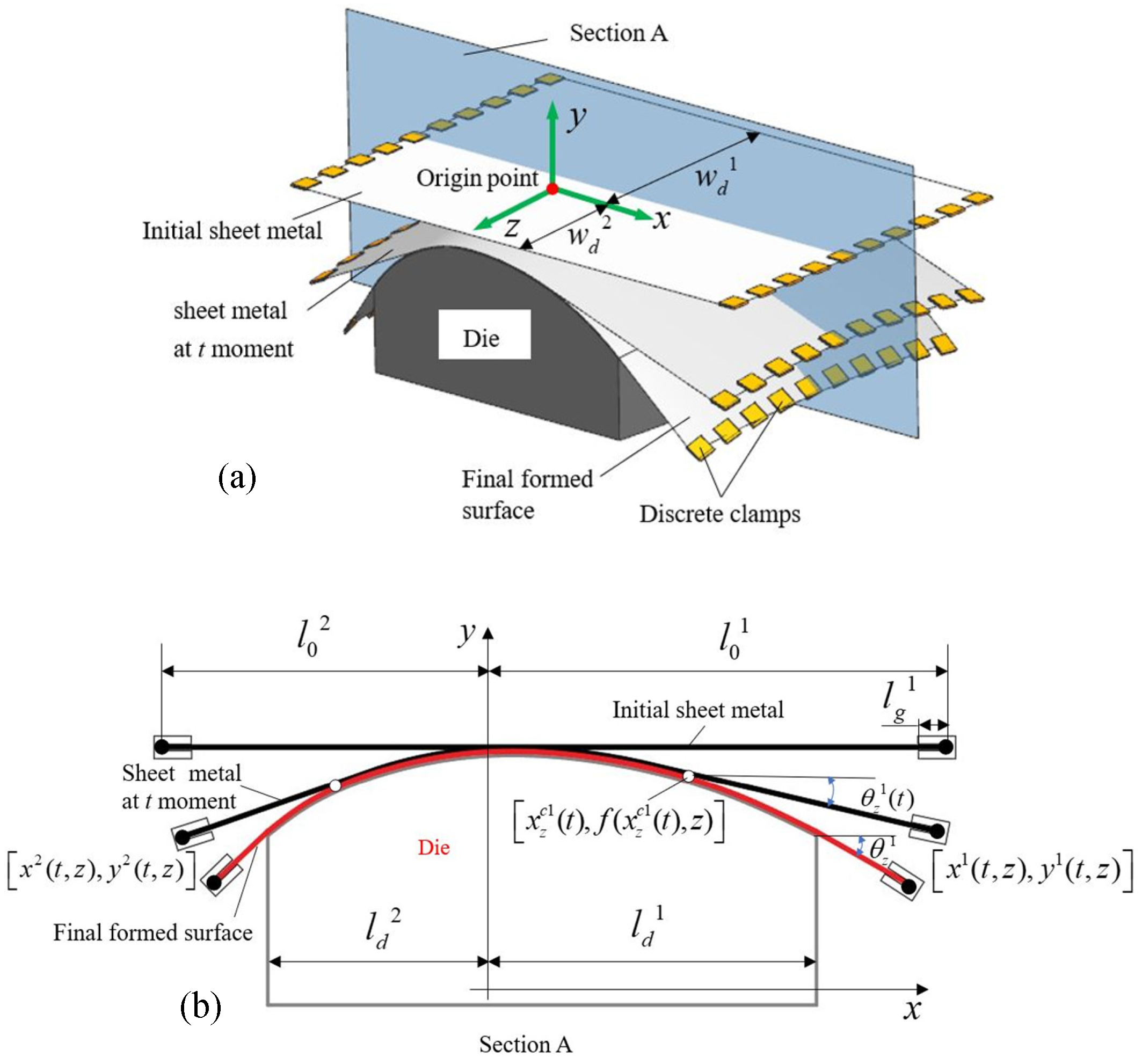
2.1. Description of Forming Characteristics and Process

In SF-CMPC, discrete clamps evenly distributed on both sides of the die are used, each one corresponding to an independent clamping block, and SF-C’s overall clamping plate is replaced, as shown in Figure 2 (SolidWorks 2018 used, China). Each clamp is connected to a pair of hydraulic cylinders through a universal joint to enable clamp swinging (as shown in Figure 3a). Through controlling the piston rod’s movement in the vertical and inclined hydraulic cylinders through CNC, the corresponding clamp can achieve different spatial positions. Then, each clamp, corresponding to a discrete point on the sheet metal, grips the latter, applying the load to the discrete point for stretch forming.
During stretch forming, each discrete clamp’s motion path can be designed based on the target surface characteristics, with its spatial positioning changing in real time with the die surface (as shown in Figure 3b), and the sheet metal can make full contact with the die without the need for a long transition zone. In addition, the clamp’s movement can be independently controlled, reducing the deformation unevenness in various surface areas and avoiding defects. When the forming process is completed, a small amount of excess material can be removed to obtain an ideal surface, achieving near-net stretch forming.

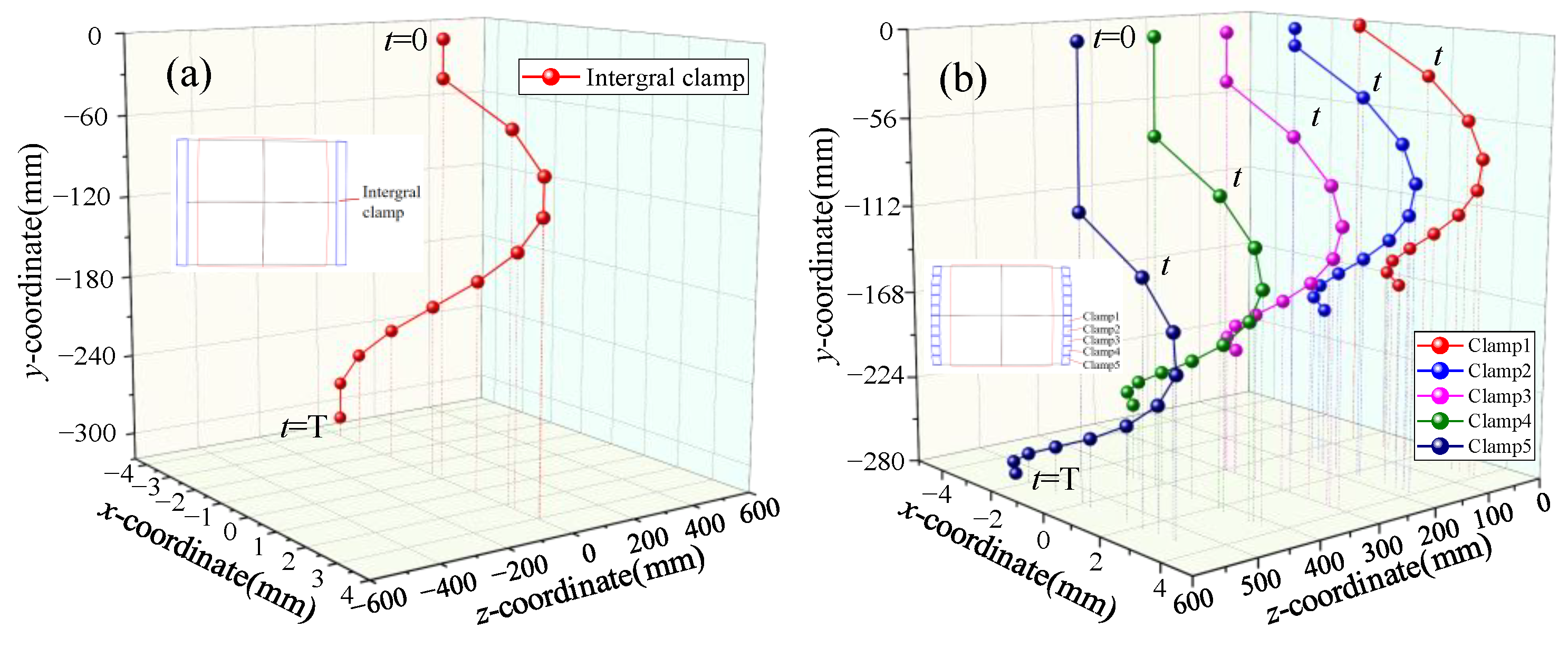
2.2. Discrete Point Loading Path Design

To apply this loading method to any surface, the target surface shape is defined by the function below, while the die’s highest point is the coordinate origin, as shown in Figure 4a. The distance between the longitudinal edge of the die and the coordinate origin is denoted by l d 1 and l d 2 , respectively. The initial sheet material’s width is the same as that of the die. The z-coordinates of the die’s transverse edges are denoted by w d 1 and w d 2 , respectively. l 0 1 and l 0 2 are used to represent the x-coordinates at both ends of the sheet metal, as shown in Figure 4b. Since the trajectory calculation method for discrete points on both sides of sheet metal is the same, only the discrete point trajectories on the right are analyzed for convenience.
In any section perpendicular to the z axis, the length of the corresponding die’s contour curve s 1 ( z ) and the angle between the tangent line of the die edge and the x axis θ z 1 can be expressed as follows:
s 1 ( z ) = 0 l d 1 1 + f ( x , z ) x 2 1 / 2 d x
θ z 1 = arctan f ( x , z ) x x = l d 1
To facilitate the control of the sheet deformation process, the relation between the sheet length l 1 ( t , z ) and the forming time t in this section is given as follows:
l 1 ( t , z ) = 0 l 0 1 l g 1 1 + ε l ( z ) ψ ( t ) d x + l g 1
where l g 1 is the length of the sheet material held by the clamps, and, if the forming end time is defined as T, ε l ( z ) is the longitudinal strain corresponding to time T. This is a function of the loading time t, and the following conditions are satisfied:
ψ ( 0 ) = 0 ψ ( T ) = 0 T ψ ( t ) d t = 1   and   ψ ( t ) > 0
For simplicity, when ψ ( t ) = t / T , the sheet metal can be considered approximately uniformly elongated, and the contact area with the die is uniformly extended along the stretching direction. One can then assume that the coordinate of the critical contact point between the sheet metal and the die contour in this section at time t is defined as x z c 1 ( t ) , f ( x z c 1 ( t ) , z ) . The x-coordinate x z c 1 ( t ) can be obtained by solving the following equation:
0 x z c 1 ( t ) 1 + f ( x , z ) x 2 1 / 2 d x = ψ ( t ) s 1 ( z )
Then, the angle between the tangent line at the critical contact point and the x axis is determined by the following equation:
θ z 1 ( t ) = arctan f ( x , z ) x x = x z c 1 ( t )
The coordinate corresponding to the longitudinal fibrous end of the metal sheet at time t is defined as x 1 t , z ,     y 1 ( t , z ) , which can be obtained by solving the following equation:
x 1 ( t , z ) = x z c 1 ( t ) + l 1 ( t , z ) ψ ( t ) s 1 ( z ) cos θ z 1 ( t ) y 1 ( t , z ) = f x z c 1 ( t ) , z l 1 ( t , z ) ψ ( t ) s 1 ( z ) sin θ z 1 ( t )
The z-coordinates of the discrete loading points can be inserted into Formula (7) to determine each spatial position. Through controlling the motion of each discrete clamp according to the loading paths described above, complete contact between the sheet and the die can be achieved within a smaller transition zone. Sheet metal deformation and the contact process with the die are controlled, effectively suppressing wrinkling and cracking. Figure 5 (Origin 2018 used, China) shows the motion paths of the clamps in SF-C and SF-CMPC, when a spherical part with curvature radii of 1500 mm, a length and width of 1200 mm is formed.

2.3. Establishment of Finite Element Model

In view of the deformation complexity, the wrinkling and cracking problems cannot simply be analyzed via the analytical method. In this study, symmetric convex surfaces were adopted as the research objects, numerically simulating the surface deformation processes using the software ABAQUS 6.14-2. The aluminum alloy of 2024-O was used as the sheet material, following the performance parameters listed in Table 1.
In sheet metal stretching, stress distribution in the thickness direction can be ignored and is generally defined as a shell element to improve computational efficiency. The forming die and the clamps with minimal deformation were hereby defined as rigid bodies. The clamps’ motion paths were controlled by applying displacement loads in the X and Y directions. As oil lubrication is usually applied during stretching to avoid scratches, 0.1 was used as the friction coefficient between the sheet and the die in our numerical simulation [24]. Due to the symmetry of the target surface, the model was simplified to a quarter of its original size to save calculation time, according to Figure 6.

3. Analysis of the Transition Zone Length’s Influence on the Stretch Forming Result

The material utilization rate is determined by the length of the transition zone. As such, how to obtain high-quality curved surfaces with small transition zones and achieve near-net forming has always been the focus of research on stretch forming. In previous studies, low-carbon steel stretching has been analyzed, forming the desired surface over a small transition zone. However, due to the high strength and low plasticity of aluminum alloys, higher requirements are placed on this forming process. In this study, a convex, curved surface with transverse and longitudinal curvature radii of 1500 mm and 1700 mm, respectively, and a length and width of 1200 mm was selected as the target. Aluminum alloy sheets with transition zone lengths of 50 mm, 150 mm, and 300 mm were selected, numerically simulating the stretch-forming processes. The influence of the transition zone length on the quality in different methods was analyzed, alongside discussions on the feasibility of improving material utilization under high-quality product conditions.

3.1. SF-C Results Corresponding to Different Transition Zone Lengths

Figure 7 shows the stress distribution on curved surfaces obtained by SF-C under different transition zone lengths, demonstrating that the latter have a significant impact on the surface deformation results. For instance, with a 50 mm transition zone length, the sheet metal touching the die edge exhibits severe stress, resulting in cracking. The main factor determining stress distribution is the change in curvature between the die edge and the transition zone, which can cause changes in the geometric shape and energy state of the grain boundaries, hindering the movement of atoms between grains. With the increase in the transition zone length, the above phenomenon is gradually improved, leading to a more uniform stress distribution. This indicates that, in SF-C, it is necessary to retain a sufficiently long transition zone to obtain high-quality surfaces and that excellent products cannot be attained in small transition zones.

3.2. SF-CMPC Results Corresponding to Different Transition Zone Lengths

The stress distributions of SF-CMPC-formed curved surfaces with different transition zone lengths are shown in Figure 8, highlighting, by comparison, that they are not significantly different. The curvature changes between the die edge and the transition zone of the sheet metal are not significant, not affecting the movement of atoms during plastic deformation. Therefore, the sheet metal touching the die edge does not exhibit stress, meaning that a higher quality of results can be obtained in smaller transition zones.
To quantitatively analyze the influence of the transition zone length on the quality of surfaces produced via different methods, the maximum effective strain and thinning values of various samples were extracted, as shown in Table 2. In SF-C, by increasing the transition zone length, the maximum thickness and strain value of the curved surface could be reduced by 79.6% and 77.0%, respectively, while, in SF-CMPC, they were reduced by only 0.010 mm and 0.0249. This shows that the dependence of production quality on the transition zone length can be reduced via clamp discretization and motion path control. Therefore, in the SF-CMPC process, the transition zone length can be minimized to reduce the cutting allowance after production, thereby achieving the near-net formation of three-dimensional curved surfaces.

4. Analysis of Cracking and Wrinkling in Stretch Forming

4.1. Cracking-Risk Analysis of Different Stretch-Forming Methods

In the stretch-forming process, sheet metal deformation is mainly realized by longitudinal stretching and thickness reduction. However, when the sheet metal’s local area is stretched or its thickness reduced to a certain extent, the sheet cracks, not guaranteeing a smooth continuation of production. Indeed, the surface thus obtained does not meet the use requirements. To study the cracking risk of SF-C and SF-CMPC, the two processes were analyzed via numerical simulation. Figure 9 shows the strain distribution on the same surface, formed by different methods. The deformation in the red area is greater than in the other ones. Indeed, when a surface with a large curvature is formed, there is a high risk of cracking. For the convenience of discussion and analysis, this area is defined as the crack danger zone.
To analyze the adaptability of stretch-forming methods in terms of obtaining surfaces with different curvatures, convex surfaces (1200 mm in length, 600 mm in width) with transverse curvatures of 0.002, 0.0025, and 0.0033 (the longitudinal curvature is 0.0005) were selected as the research objects, simulating the deformation processes of the two different approaches. The forming limit curve obtained using the Keeler method [30] to analyze the risk of cracking in this article. The strain values in the crack danger zone were extracted and plotted in a forming limit diagram, as shown in Figure 10. The cracking risk is usually evaluated using the ratio of the maximum principal strain on the formed surface (MSFS) to the minimum principal strain on the forming limit curve (MSFLC): the higher this ratio, the greater the risk of cracking.
Through comparison, the strain value of the SF-C surface changed significantly with the curvature, with an MSFS-to-MSFLC ratio in some areas being close to or even greater than 1, which could result in cracking. In SF-CMPC, the deformation also increased as the curvature increased, but the strain change amplitude was significantly smaller. When surfaces with different curvatures were formed, the MSFS-to-MSFLC ratios were all less than 0.65, without any cracking defects. Therefore, surface deformation and cracking risk can be controlled and reduced, respectively, by designing the clamps’ motion paths. The SF-CMPC method exhibits better adaptability for forming surfaces with large curvatures.

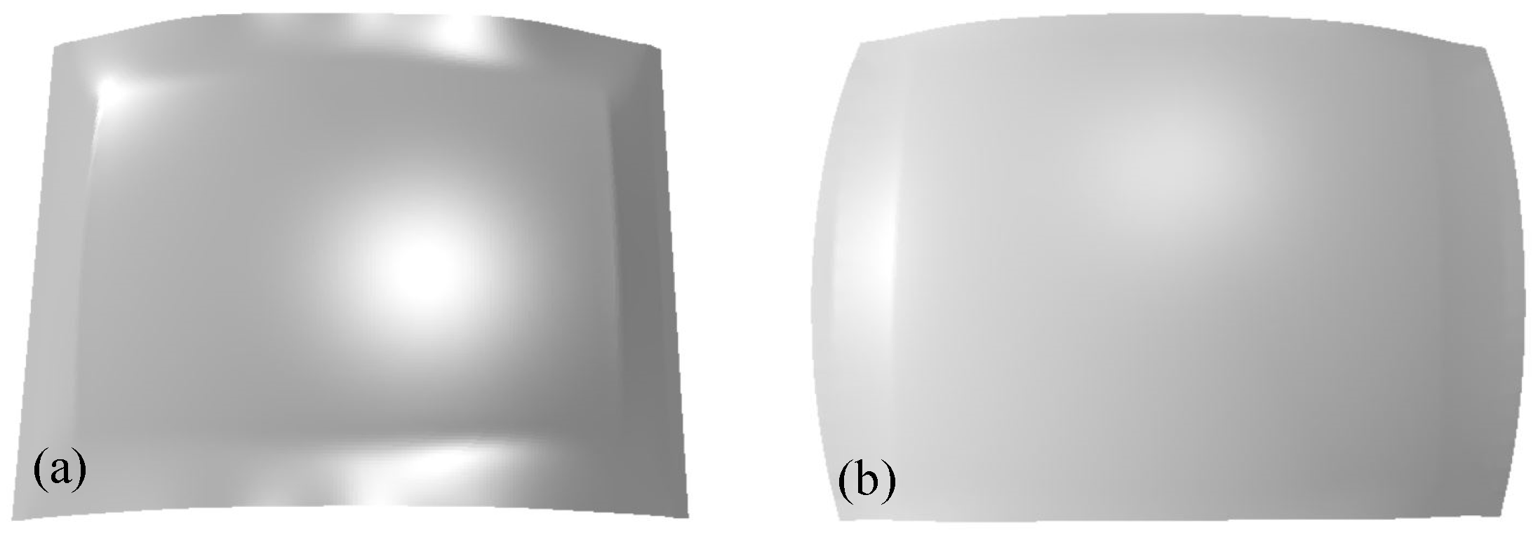
4.2. Sheet Metal Wrinkling and Its Contact Process with the Die

To analyze the wrinkling of curved surfaces formed by different methods, a spherical product with a 1500 mm curvature radius, a 1200 mm length, and a 1200 mm width was selected as the research object, numerically simulating the different formation processes. The final states of the obtained surfaces are shown in Figure 11. The central region of the SF-C surface exhibits an ideal shape, but the edges present warping and wrinkling, making it difficult to meet the usage requirements through subsequent trimming. The SF-CMPC surface is smooth and not wrinkled, meaning that, after production, a small amount of excess material can be removed without trimming.
There was a significant difference in the wrinkling of the surfaces obtained following the two methods. To analyze the contact between the surface and the die during the different formation processes, nine feature points (see Figure 12) on the formed surfaces were selected. By extracting the coordinates of each point and comparing the calculations, the distance from the die in the y direction was obtained, and a relationship with the forming rates was established, as shown in Figure 10. When the value of the distance was zero, the sheet metal was in contact with the die. In SF-C, feature points 1, 2, 4, and 5 were the first to come into contact with the higher central area of the die, while 3, 6, and 9 in the wrinkled edge area remained suspended, with no contact. In SF-CMPC, points 1–3, 4–6, and 7–9 sequentially touched the die by designing each clamp’s motion path, and feature points with the same x-coordinate made contact with the die at the same time.

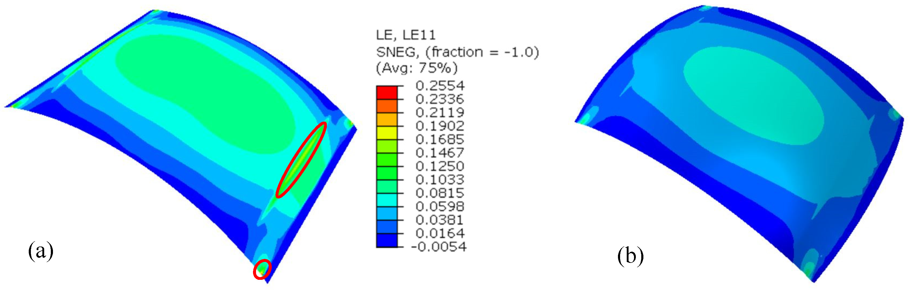
4.3. Stress–Strain Analysis of the Formed Surface

To discover the relationship between the stress and strain distribution on the formed surface, these measures were analyzed alongside die contact and wrinkling. Figure 13 shows the transverse stresses and strains along three characteristic lines on the SF-C surface. The transverse stress variation in the area where the sheet metal touches the die is relatively small, but the stress fluctuation in the suspended area is significant, with a maximum compressive stress of nearly 100 MPa. The compressive strain at the corresponding position increases slightly as a result. Due to insufficient constraints on the suspended sheet material, the ultimate compressive strain is relatively small, making the surface prone to warping and wrinkling.
The stress and strain of the curved SF-CMPC surface are shown in Figure 14. The amplitude of the transverse compressive stress variation along the characteristic line is very small. Due to the complete contact between the sheet metal along this same characteristic line and the die, sufficient constraints are ensured, increasing the ultimate compressive strain. In addition, the mutual friction between the die and the still-forming surface can suppress the transverse shrinkage, reducing the possibility of wrinkling. Therefore, by controlling the clamps’ movement paths, the manner of contact between the sheet metal and the die can be changed, improving the sheet metal’s stress and strain distribution and suppressing wrinkling.

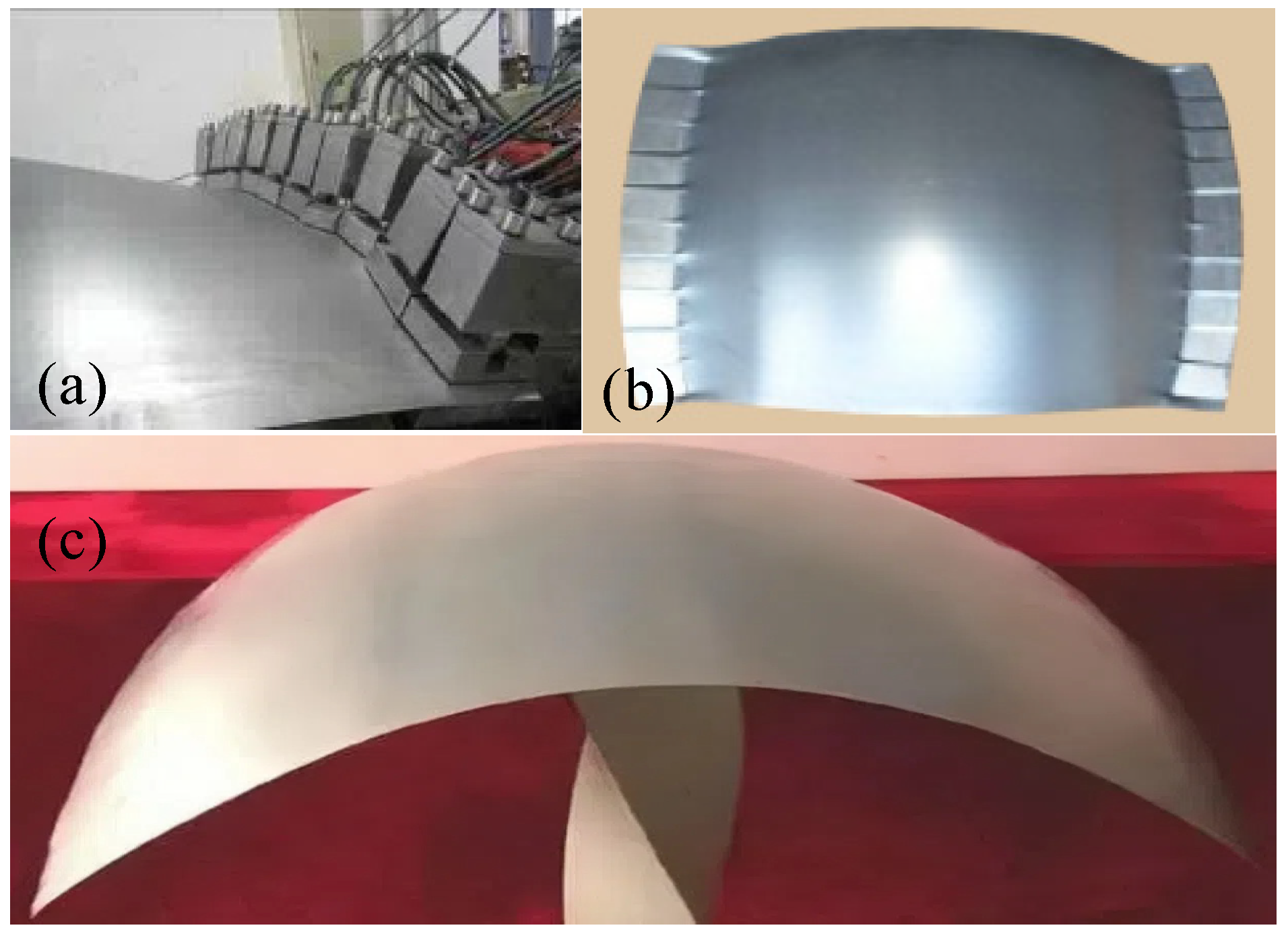
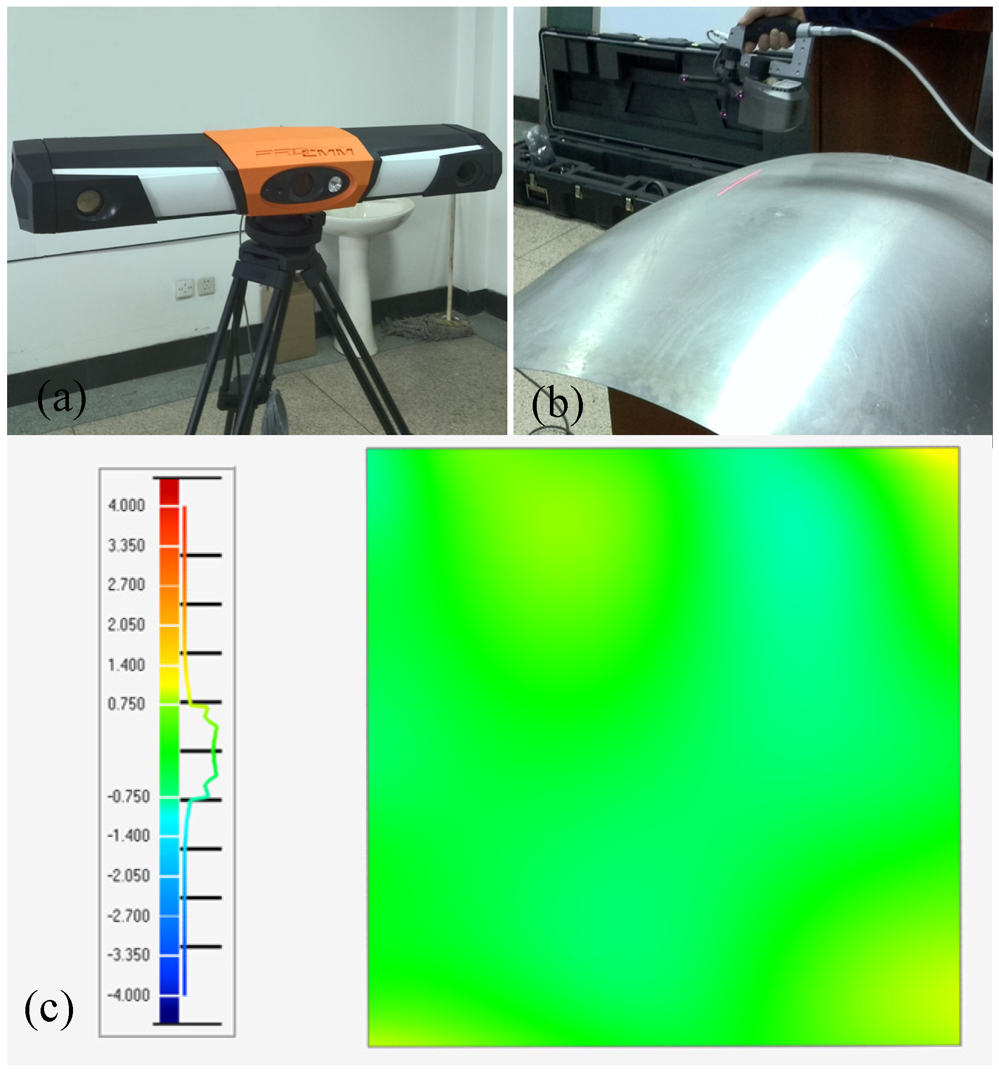
5. Experimental Verification

We conducted experiments to verify the surface formation results obtained in small transition zones based on discrete clamp motion path control. A 2024-O aluminum alloy sheet with a 1 mm thickness was selected as the experimental material in this study, and a spherical surface underwent stretch forming using self-developed equipment. The curvature radius was 1500 mm, with 1200 mm for both length and width. During the formation process, the sheet metal was gripped by 10 discrete clamps on both sides. The clamps were controlled according to the motion path designed in Section 2.2. The spatial arrangement of which, for a certain moment in time, is shown in Figure 15a. The surface’s deformation state after the formation is shown in Figure 15b, with no cracking or wrinkling defects. This proves that satisfactory results can be obtained when forming surfaces with large curvatures in small transition areas. Following this method, the final surface (Figure 15c) can be obtained by removing a small amount of excess material corresponding to the clamping and transition areas.
The surface shape was measured using an optical 3D measuring instrument, as shown in Figure 16a. The measurement error of the instrument was less than 40 μm. The scanning process is shown in Figure 16b. The shape of the surface can be determined through measurement data. In comparing the results with the target surface, the formation errors can be obtained. The shape error in the normal direction of the formed surface is displayed in Figure 16c. The normal errors are distributed within the range of −1.4 mm to 1.4 mm, concluding that high-quality three-dimensional surfaces can be obtained based on discrete clamp motion path control.

6. Conclusions

A surface near-net stretch-forming method based on discrete clamp motion path control is proposed in this study. Following this approach, the sheet metal is guaranteed to make complete contact with the die at a smaller transition zone length, a surface with a large curvature and no defects can be obtained, and good deformation uniformity is maintained. Two forming processes were numerically analyzed based on finite element software, alongside experimental verification. The conclusions are summarized as follows:
(1)
The dependence of production quality on the transition zone length can be reduced by means of clamp discretization and motion path control. A satisfactory quality can be achieved with a smaller transition zone length, and the proportion of residual material removed after forming can be reduced.
(2)
There is a significant difference in the cracking risk of surfaces with different curvatures obtained following the two stretch-forming methods. In SF-C, the strain in the crack danger zone varies significantly with the surface curvature. The cracking risk is extremely high with highly curved surfaces, and these may even crack during production. Therefore, in SF-CMPC, the clamps are discretized, and their motion paths are designed and controlled. The cracking risk can be reduced, exhibiting better adaptability for the formation of surfaces with a large curvature.
(3)
In SF-C, the sheet metal comes into passive contact with the die. The edge area of the sheet metal is in a suspended state, with a relatively small ultimate compressive strain. Wrinkles are prone to occur. In SF-CMPC, the clamps’ motion paths are controlled to ensure that the sheet metal in the transverse section is in contact with the die at the same time. Due to the friction between the sheet metal and the die, transverse shrinkage can be suppressed, and the transverse compressive stress, reduced. In addition, the sheet metal is always sufficiently constrained, the ultimate compressive strain can be increased, and wrinkling can be suppressed during production.
(4)
The experiment of stretch forming a spherical surface was carried out using self-developed equipment. Wrinkles and cracks did not occur on the surface. The normal error between the formed part and the target surface was distributed within the range of −1.4 mm to 1.4 mm. The feasibility of stretch forming by controlling clamps’ motion paths has been proven.
However, there are limitations to this method, needing further research and optimization. Although good adaptability was exhibited when forming unimodal surfaces with SF-CMPC, when complex surfaces are formed, it will be difficult for some sheet metal areas to touch the die. Next, composite formation processes, combining SF-CMPC with others (such as incremental forming, multi-point forming, etc.), can be explored to widen the range of achievable surface shapes. Springback compensation and clamp motion path optimization can be implemented to obtain higher-precision surfaces.

Author Contributions

Conceptualization, Z.Y. and Q.T.; methodology, Z.Y. and Q.T.; software, Z.Y.; validation, Z.Y.; investigation, Z.Y. and Q.T.; data curation, Z.Y.; writing—original draft preparation, Z.Y.; and writing—review and editing, Z.Y. and Q.T. All authors have read and agreed to the published version of the manuscript.

Funding

This research was funded by the Dalian High-Level Talent Innovation Support Program of the Scientific and Technological Office of Dalian, with project no. 2020RQ106.

Data Availability Statement

The original contributions presented in the study are included in the article, further inquiries can be directed to the corresponding authors.

Conflicts of Interest

The authors declare no conflicts of interest.

References

  1. Seo, Y.-H.; Kang, B.-S.; Kim, J. Study on relationship between design parameters and formability in flexible stretch forming process. Int. J. Precis. Eng. Manuf. 2012, 13, 1797–1804. [Google Scholar] [CrossRef]
  2. Wei, B.; Wei, Y.; Zhang, F.; He, K.; Dang, X.; Du, R. Springback control and plastic deformation of metal plates with large curvature in heat-assisted incremental bending process. Int. J. Adv. Manuf. Technol. 2021, 112, 1483–1500. [Google Scholar] [CrossRef]
  3. Gupta, P.; Szekeres, A.; Jeswiet, J. Manufacture of an aerospace component with hybrid incremental forming methodology. Int. J. Mater. Form. 2021, 14, 293–308. [Google Scholar] [CrossRef]
  4. Wang, L.; Luan, X.; Liu, S.; Wang, X. Analysis of wall thickness evolution and forming quality of sheet metal manufactured by wrinkles-free forming method. Int. J. Mater. Form. 2024, 17, 44. [Google Scholar] [CrossRef]
  5. Yuan, S.J. Fundamentals and Processes of Fluid Pressure Forming Technology for Complex Thin-Walled Components. Engineering 2021, 7, 358–366. [Google Scholar] [CrossRef]
  6. Chen, Y.Z.; Liu, W.; Xu, Y.C.; Yuan, S.J. Analysis and experiment on wrinkling suppression for hydroforming of curved surface shell. Int. J. Mech. Sci. 2015, 104, 112–125. [Google Scholar] [CrossRef]
  7. Cui, X.H.; Yan, Z.Q.; Chen, B.G.; Du, Z.H.; Xiao, A.; Yu, H.L. Large ellipsoid parts manufacture using electromagnetic incremental forming with variable blankholder structure. Int. J. Adv. Manuf. Technol. 2021, 116, 3699–3715. [Google Scholar] [CrossRef]
  8. Leonhardt, A.; Kurz, G.; Victoria-Hernández, J.; Kräusel, V.; Landgrebe, D.; Letzig, D. Experimental study on incremental sheet forming of magnesium alloy AZ31 with hot air heating. Procedia Manuf. 2018, 15, 1192–1199. [Google Scholar] [CrossRef]
  9. Duflou, J.R.; Callebaut, B.; Verbert, J.; Baerdemaeker, H.D. Improved SPIF performance through dynamic local heating. Int. J. Mach. Tools Manuf. 2008, 48, 543–549. [Google Scholar] [CrossRef]
  10. Zhang, X.Q.; Liu, H.X.; Wang, Y.K.; Duan, S.W.; Zhang, Y.; Fang, J.X.; Pei, S.B.; Hu, W.F. Research on dynamic deformation behaviors of laser driving metal sheet precision forming. Int. J. Solids Struct. 2024, 288, 112631. [Google Scholar] [CrossRef]
  11. Du, Z.; Yan, Z.; Cui, X.; Chen, B.; Yu, H.; Qiu, D.; Xia, W.; Deng, Z. Springback control and large skin manufacturing by high-speed vibration using electromagnetic forming. J. Mater. Process. Technol. 2022, 299, 117340. [Google Scholar] [CrossRef]
  12. Xiao, A.; Yan, Z.Q.; Huang, C.Q.; Yu, Z.X.; Wang, S.P.; Cui, X.H. Reduction of springback of Ti6Al4V alloy by high-density and instantaneous pulsed current. Mater. Sci. Eng. A-Struct. Mater. Prop. Microstruct. Process. 2023, 877, 145188. [Google Scholar] [CrossRef]
  13. Abdel-Nasser, Y.; Ma, N.; Rashed, K.M.H. Numerical Modelling for Efficient Analysis of Large Size Multi-Stage Incremental Sheet Forming. J. Manuf. Mater. Process. 2024, 8, 3. [Google Scholar] [CrossRef]
  14. Sorrentino, L.; Parodo, G.; Giuliano, G. Lightweight Structures: An innovative method to uniform the thickness of metal sheets by patchwork blanks. Int. J. Lightweight Mater. Manuf. 2021, 5, 20–28. [Google Scholar] [CrossRef]
  15. He, D.-H.; Li, X.-Q.; Li, D.-S.; Yang, W.-J. Process design for multi-stage stretch forming of aluminium alloy aircraft skin. Trans. Nonferrous Met. Soc. China 2010, 20, 1053–1058. [Google Scholar] [CrossRef]
  16. Zhao, X.; Ou, H. A new hybrid stretch forming and double-layer two-point incremental sheet forming process. J. Mater. Res. Technol. 2024, 30, 3485–3509. [Google Scholar] [CrossRef]
  17. Siegert, K.; Fann, K.J.; Rennet, A. CNC-Controlled Segmented Stretch-Forming Process. CIRP Ann. 1996, 45, 273–276. [Google Scholar] [CrossRef]
  18. Siegert, K.; Rennet, A.; Fann, K.J. Prediction of the final part properties in sheet metal forming by CNC-controlled stretch forming. J. Mater. Process. Technol. 1997, 71, 141–146. [Google Scholar] [CrossRef]
  19. Han, Q.; Wang, J.; Han, Z.; Niu, S.; Zhang, J.; Liu, Z.; Li, M. Design of a flexible bio-inspired stretch-forming machine for the fabrication of large radius bends parts. Int. J. Adv. Manuf. Technol. 2020, 108, 3571–3578. [Google Scholar] [CrossRef]
  20. Peng, H.; Li, M.-Z.; Han, Q.; Feng, P.; Chen, X. Numerical Investigation of Flexible Holding Technology for Stretch Forming Process. Appl. Mech. Mater. 2011, 121–126, 2126–2130. [Google Scholar] [CrossRef]
  21. Peng, H.; Li, M.-Z.; Han, Q.; Feng, P.; Zhang, H. Design of Flexible Multi-Gripper Stretch Forming Machine by FEM. Adv. Mater. Res. 2011, 328–330, 13–17. [Google Scholar] [CrossRef]
  22. Park, J.-W.; Kim, J.; Kim, K.-H.; Kang, B.-S. Numerical and experimental study of stretching effect on flexible forming technology. Int. J. Adv. Manuf. Technol. 2014, 73, 1273–1280. [Google Scholar] [CrossRef]
  23. Wang, Y.; Li, M.; Wang, D.; Wang, A. Modeling and numerical simulation of multi-gripper flexible stretch forming process. Int. J. Adv. Manuf. Technol. 2014, 73, 279–288. [Google Scholar] [CrossRef]
  24. Wang, Y.; Li, M.-z. Research on three-dimensional surface parts in multi-gripper flexible stretch forming. Int. J. Adv. Manuf. Technol. 2014, 71, 1701–1707. [Google Scholar] [CrossRef]
  25. Yanyan, C.; Mingzhe, L.I.; Jian, X.; You, W. Research of Multi-gripper Flexible Stretch Forming for Irregular Part. J. Mech. Eng. 2014, 50, 90–96. [Google Scholar] [CrossRef]
  26. Cai, Z.-Y.; Liang, X.-b.; Yang, Z.; Li, X.-J. Force-controlled sheet metal stretch-forming process based on loading at discrete points. Int. J. Adv. Manuf. Technol. 2017, 93, 1781–1789. [Google Scholar] [CrossRef]
  27. Yang, Z.; Cai, Z.-Y.; Che, C.-J.; Li, M.-Z. Numerical simulation research on the loading trajectory in stretch forming process based on distributed displacement loading. Int. J. Adv. Manuf. Technol. 2016, 82, 1353–1362. [Google Scholar] [CrossRef]
  28. Venturato, G.; Ghiotti, A.; Bruschi, S. Stress-state dependent formability modelling in hot stamping. Prod. Eng. 2019, 14, 105–114. [Google Scholar] [CrossRef]
  29. Werber, A.; Liewald, M.; Nester, W.; Martin, G.; Wiegand, K.; Simon, J.; Jürgen, T.; Hotz, W. Assessment of forming limit stress curves as failure criterion for non-proportional forming processes. Prod. Eng. 2013, 7, 213–221. [Google Scholar] [CrossRef]
  30. Keeler, S.P.; Brazier, W.G. Relationship between laboratory material characterization and press-shop formability. Microalloying 1975, 75, 517–530. [Google Scholar]
Figure 1. SF-C schematic.
Metals 14 01046 g001
Figure 2. Clamp configuration: (a) internal structure of discrete clamp displayed by cutting into the middle of the clip; (b) the overall clamping plate in SF-C.
Metals 14 01046 g002
Figure 3. SF-CMPC: (a) initial state and (b) spatial arrangement of discrete clamps.
Metals 14 01046 g003
Figure 4. Schematic of the stretch-forming process: (a) sheet metal deformation and (b) view of cross-section A.
Metals 14 01046 g004
Figure 5. Motion paths of the clamps (a) SF-C and (b) SF-CMPC.
Metals 14 01046 g005
Figure 6. FE models of different forming methods: (a) SF-C and (b) SF-CMPC.
Metals 14 01046 g006
Figure 7. Stress distributions on curved surfaces obtained by SF-C under different transition zone lengths: (a) 50 mm; (b) 150 mm; and (c) 300 mm.
Metals 14 01046 g007
Figure 8. Stress distributions on curved surfaces obtained by SF-CMPC under different transition zone lengths: (a) 50 mm; (b) 150 mm; and (c) 300 mm.
Metals 14 01046 g008
Figure 9. Analysis of the crack danger zone: (a) SF-C and (b) SF-CMPC.
Metals 14 01046 g009
Figure 10. Strain distributions in the forming limit diagram: (a) SF-C and (b) SF-CMPC.
Metals 14 01046 g010
Figure 11. The wrinkled state of the final surfaces obtained via (a) SF-C and (b) SF-CMPC.
Metals 14 01046 g011
Figure 12. The variation in the distance between the feature points and the die during formation: (a) SF-C and (b) SF-CMPC.
Metals 14 01046 g012
Figure 13. Transverse stresses and strains along the three characteristic lines on the SF-C surface.
Metals 14 01046 g013
Figure 14. Transverse stresses and strains along the three characteristic lines on the SF-CMPC surface.
Metals 14 01046 g014
Figure 15. Spherical surface experiment: (a) spatial arrangement of discrete clamps; (b) surface at end of formation process; and (c) final surface.
Metals 14 01046 g015
Figure 16. Analysis of forming error: (a) optical tracker; (b) scanning process; and (c) distribution diagram of normal error.
Metals 14 01046 g016
Table 1. Performance parameters of 2024-O.
Material PropertiesValue
Density (kg/m3)2780
Young’s modulus (GPa)73
Poisson’s ratio0.33
Yield strength (MPa)75.3
Tensile strength (MPa)191
Table 2. The deformation results of different methods with varying transition zone lengths.
Transition Zone Length (mm)SF-C SF-CMPC
Max Thickness
Reduction (mm)
Max Effective Strain ValueMax Thickness
Reduction (mm)
Max Effective Strain Value
500.25160.32820.04610.0868
1500.10420.14030.03810.06355
3000.05140.07550.03640.06194
Disclaimer/Publisher’s Note: The statements, opinions and data contained in all publications are solely those of the individual author(s) and contributor(s) and not of MDPI and/or the editor(s). MDPI and/or the editor(s) disclaim responsibility for any injury to people or property resulting from any ideas, methods, instructions or products referred to in the content.

