Article

The Preparation and Properties of a Ni-SiO2 Superamphiphobic Coating Obtained by Electrodeposition

1
Shandong Key Laboratory of Oil & Gas Storage and Transportation Safety, College of Pipeline and Civil Engineering, China University of Petroleum (East China), Qingdao 266580, China
2
CNPC Offshore Engineering Qingdao Co., Ltd. (CPOE), Qingdao 266500, China
3
Offshore Oil Engineering (Qingdao) Co., Ltd., Qingdao 266520, China
*
Authors to whom correspondence should be addressed.
Metals 2024, 14(9), 1047; https://doi.org/10.3390/met14091047
Submission received: 22 August 2024 / Revised: 9 September 2024 / Accepted: 11 September 2024 / Published: 14 September 2024

Abstract

:
Superamphiphobic coatings have shown great potential in many fields such as with their anti-corrosion, high-temperature resistance, self-cleaning, and drag reduction properties. However, due to the poor stability of their coatings, it is difficult to apply them on a large scale. In this paper, two kinds of SiO2 particles and nickel were co-deposited on the surface of steel to construct a micro/nano dual-scale structure by composite electrodeposition. The surface of the coating was then fluorinated with the low-surface-energy material 1H,1H,2H,2H-Perfluorodecyltriethoxysilane (AC-FAS) to prepare a Ni-SiO2 superamphiphobic coating. The coating has a water contact angle of 159° and an oil contact angle of 151°. The effect of nanoparticle concentration on the wettability and surface morphology of the coating was systematically studied. Comparative experiments revealed that the optimal micro/nanoparticle concentrations were 8 g/L of 20 nm SiO2 and 2 g/L of 1 μm SiO2. This preparation method greatly improves the corrosion resistance, wear resistance, chemical stability, and high-temperature resistance of the coating.

1. Introduction

Carbon steel is widely used in the oil and gas industry because of its excellent mechanical properties, abundant raw materials and straightforward smelting process. However, the surface of carbon steel is highly susceptible to wetting by droplets, leading to corrosion that significantly reduces the service life of storage and transportation equipment, such as pipelines. This corrosion results in substantial economic losses, resource wastage, and safety hazards for personnel [1]. Therefore, implementing effective anti-corrosion measures on carbon steel surfaces is crucial. Inspired by the self-cleaning properties of lotus leaves [2], researchers have demonstrated that superamphiphobic coatings can effectively prevent a metal surface from contacting corrosive media, thereby reducing the corrosion rate and greatly enhancing the metal’s corrosion resistance [3]. The application of superamphiphobic coatings on metal surfaces has thus become a key method for corrosion protection [4,5]. Additionally, superamphiphobic surfaces offer various functionalities, including drag reduction [6], anti-fogging [7], self-cleaning [8,9], self-healing [10,11,12], antibacterial properties [13], flame retardance [14,15,16], heat resistance [17,18], anti-electromagnetic interference [19], and directional liquid transport [20,21,22].
Superamphiphobic coatings can be obtained by composite electrodeposition [23], physical deposition [24], chemical vapor deposition [25], plasma etching [26], sol-gel processes [27], and template methods [28]. Wang et al. [29] used a combination of EDM and electrodeposition to prepare superamphiphobic surfaces on Al substrates with a water contact angle of 169.8 ± 3.0° and an oil contact angle of 154.5 ± 8.3°, but the coatings lost their superamphiphobic quality after 75 cm of abrasion with just 1000-grit sandpaper. Shen [23] et al. used a composite electrodeposition process to form Ni/nano-WO3/CNT metal matrix composite (MMC) superamphiphobic coatings by introducing tungsten trioxide (WO3) nanoparticles and carbon nanotubes (CNTs) into the deposited nickel metal, and the coatings lost their superamphiphobic after abrasion on a 600-grit sandpaper. Therefore, the preparation of stable superamphiphobic coatings by a simple and low-cost method is still a great challenge.
To date, superamphiphobic coatings have not seen widespread industrial application. Beyond the constraint of high production costs, a more critical issue is the generally poor stability of most superamphiphobic coatings. This instability arises from two primary factors. First, the micro/nanostructure of the superamphiphobic surface is relatively fragile; any external physical damage to this structure can directly impair the coating’s superamphiphobic properties. Second, exposure to corrosive substances can alter the chemical properties and surface structure of the coating, resulting in diminished corrosion resistance and durability. Several studies have shown that the co-deposition of nanomaterials into coatings by composite electrodeposition technique can not only refine the grain of the coating, but also effectively enhance the mechanical properties of the coating [30,31]. For example, the friction coefficient of the coating with the addition of La2O3 was reduced by 46.57% compared with that of the pure Ni-W coating [32]. With the addition of α-ZrP, the hardness of the Ni-B coating was as high as 1000.92 HV [33]. With the development of silica nanoparticles, researchers found that the microstructure, hardness, wettability and corrosion resistance of nickel-based composite coatings doped with silica nanoparticles were improved [34,35]. However, they only used single-particle-size silica particles and did not study the effect of different particle sizes of silica particles on the coating.
In this paper, silica micro/nanoparticles of varying sizes and nickel were co-deposited onto the surface of carbon steel using composite electrodeposition. The advantages of the high hardness, high strength, high abrasion resistance, corrosion resistance, oxidation resistance, and chemical stability of silicon dioxide itself and nickel metal together are utilized to construct a micro/nano dual-scale structure. The resulting Ni-SiO2 superamphiphobic coating significantly reduces the corrosion rate of the steel. Additionally, the robust micro/nanostructure on the coating’s surface ensures that its superamphiphobic properties are retained even after wear, thereby extending the coating’s lifespan.

2. Materials and Methods

2.1. Solvent Configuration and Preparation of Superamphiphobic Coating

The plating solution used in the composite electrodeposition process is the Watt plating solution, with its composition detailed in Table 1. The main salt of the plating solution is NiSO4, which supplies Ni2+ ions for the electrodeposition process. Additionally, NiCl2 is included to prevent passivation of the anode during electrodeposition. H3BO3 was added to maintain the pH value stability of the plating solution. Sodium dodecyl sulfate (SDS, Macklin, Shanghai, China) was used as an anionic surfactant to prevent the agglomeration of silica particles in the solution. The combinations of different SiO2 micro/nanoparticles are shown in Table 2. By varying the concentration of SiO2 micro/nanoparticles of different sizes, various coatings were produced.
ASTM A106B steel with a size of 30 mm × 20 mm × 2 mm was chosen as the substrate. Wires were welded to the back of the test piece, which was then encapsulated with epoxy resin. The surface to be plated was sequentially polished using 180 # to 2000 # sandpaper.
The test piece was subsequently placed in an alkali washing solution at 65 °C for 25 min. The alkali washing solution comprised 30 g/L sodium hydroxide, 40 g/L sodium carbonate, 25 g/L sodium silicate, and 20 g/L sodium phosphate. Finally, the sample surface was acid-washed and activated with a 10% dilute hydrochloric acid solution, then dried for later use.
The composite electrodeposition experiment was conducted using a two-electrode system, as illustrated in Figure 1. A nickel plate (60 mm × 40 mm × 5 mm) served as the anode, while ASTM A106B steel (30 mm × 20 mm × 2 mm) functioned as the cathode, with a spacing of 4 cm between them.
The experimental parameters for electrodeposition are detailed in Table 3. The concentration of SiO2 particles of different sizes was varied to produce distinct coatings. To ensure the homogeneous dispersion of the particles, the plating solution was subjected to ultrasonic treatment for 25 min prior to electrodeposition. After electrodeposition, anhydrous ethanol as a solvent, AC-FAS (Shanghai Aladdin Biochemical Technology Co., Ltd., Shanghai, China) as a solute, and a trace of hydrochloric acid were used to obtain the fluorosilane solution. The coated test piece was placed in an 80 °C fluorosilane solution for heat treatment for 3 h. The surface energy of the coating is greatly reduced after AC-FAS modification, which provides the coating with super-double hydrophobicity. Finally, the test piece was placed in a drying oven at a constant temperature of 115 °C for 1 h to enhance the bonding between the surface modifier and the coating.

2.2. Characterization

The water contact angle (WCA) and sliding angle (SA) of the coating surface were measured using an automatic contact angle measuring instrument (SDC-350, SINDIN, Guangzhou, China) to characterize the wettability of the coating. The surface morphology of the coating was analyzed by scanning electron microscopy (JSM-7200F, JEOL, Tokyo, Japan). The 3D morphology of the Ni-SiO2 superamphiphobic coating surface was obtained through 3D confocal morphology testing (Axio Imager A2m, Zeiss, Oberkochen, German). The elemental composition and content of the coating were determined using EDS (JSM-7200F, JEOL, Tokyo, Japan).

2.3. Coating Chemical Stability Test

The Ni-SiO2 superamphiphobic coating was immersed in 3.5 wt.% NaCl solution, and the water and oil contact angles of the sample surface were measured at specific intervals to evaluate the amphiphobic stability of the coating in a corrosive environment.

2.4. Coating Corrosion Resistance Test

In this experiment, a PARSTAT 2273 (AMETEK, Newark, DE, USA) electrochemical workstation was used for electrochemical impedance spectroscopy (EIS) and polarization curve tests. A standard three-electrode system was constructed, with the bare steel substrate, unmodified pure nickel coating, and Ni-SiO2 superamphiphobic coating serving as the working electrodes. A saturated potassium chloride electrode (SCE) was used as the reference electrode, and a platinum electrode as the auxiliary electrode. Electrochemical tests were conducted in a 3.5 wt.% NaCl aqueous solution as the corrosive medium.
The polarization curve test range was set to ±250 mV relative to the open circuit potential, with a scanning rate of 0.3 mV·s−1. The Tafel curve was extrapolated and fitted using Power Suite software (version number 2.5.8.0, AMETEK, Newark, DE, USA). For the electrochemical impedance spectroscopy test, the voltage amplitude was 10 mV, and the frequency ranged from 10 mHz to 100 kHz. The electrochemical behavior of the Ni-SiO2 superamphiphobic coating was compared and analyzed by continuously monitoring the AC impedance spectrum of the coating in the 3.5 wt.% NaCl solution. The corrosion test cycles were conducted at intervals of 1 h, 24 h, 2 days, 4 days, 8 days, and 16 days. ZView software (version number 3.1, AMETEK, Newark, DE, USA) was used to construct the equivalent circuit model and fit the impedance spectrum data.

2.5. Wear Resistance Test of the Coating

Firstly, the hardness of steel, the pure nickel coating, and the Ni-SiO2 superamphiphobic coating were tested. The hardness of the sample was tested using an FM-800 (D) micro W Vickers hardness tester (FTFuture-Tech, Tokyo, Japan). The pressure loading time was 15 s, and the load was 500 g. Five different points on the surface of each sample were tested for hardness, and the average value was recorded as the final hardness value.
Subsequently, a sandpaper friction experiment was conducted. As shown in Figure 2, a 100 g weight was placed on the coating to apply a constant pressure. The coating surface was placed face down on 400-mesh SiC sandpaper and dragged at a constant speed of 1.4 cm/s. The wear resistance of the coating was characterized by measuring the relationship between the water–oil contact angle and the friction distance on the coating surface.

2.6. High-Temperature Resistance Test of the Coating

The high-temperature resistance of Ni-SiO2 superhydrophobic coatings was tested by conducting high-temperature experiments. The coatings were heated in incubators at 100, 150, 200, 250, and 300 °C for 1 h each. After the coatings cooled to room temperature, the surface was rinsed with deionized water followed by anhydrous ethanol. The contact angle of the coating surface was then measured to evaluate its high-temperature resistance.

3. Results and Discussion

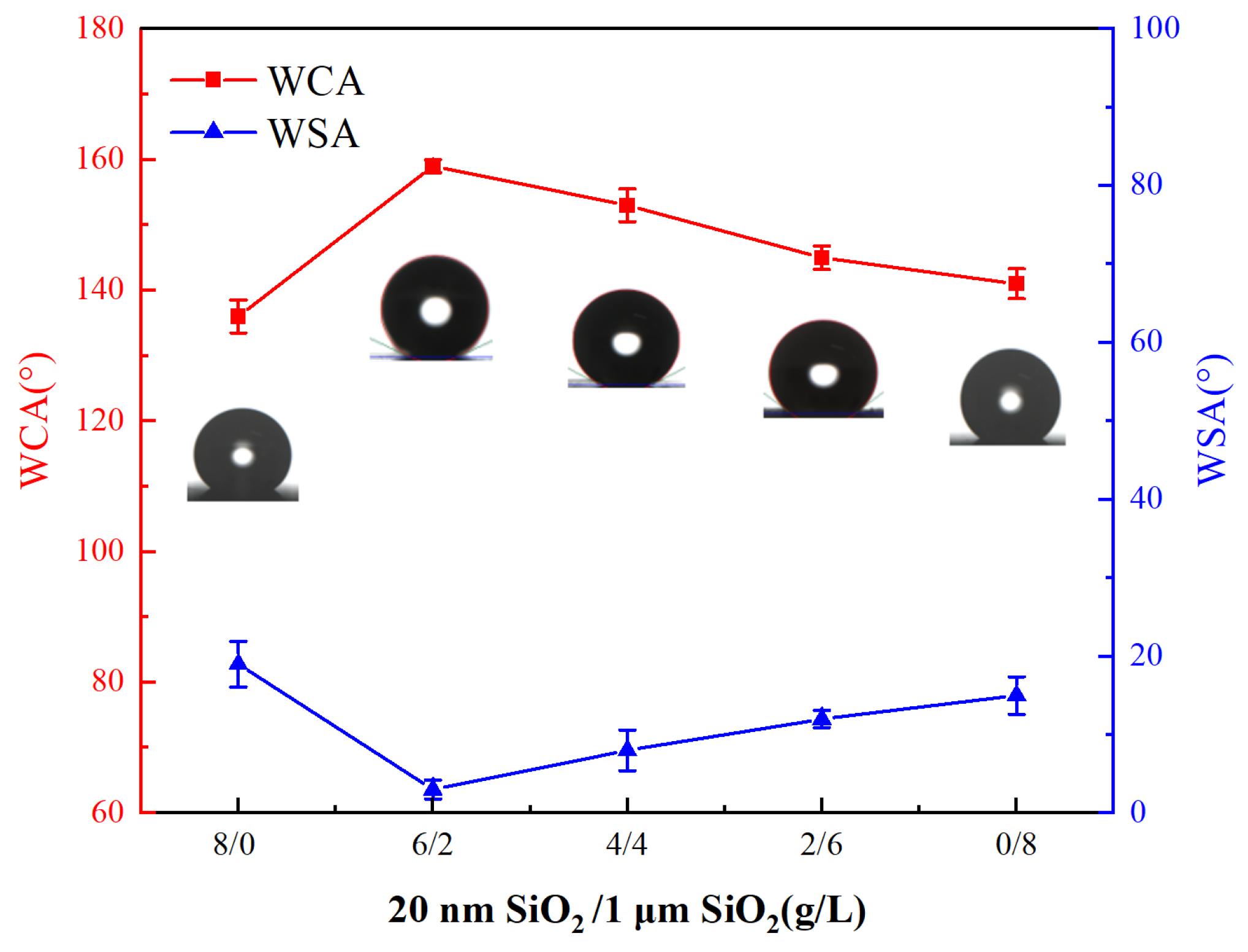
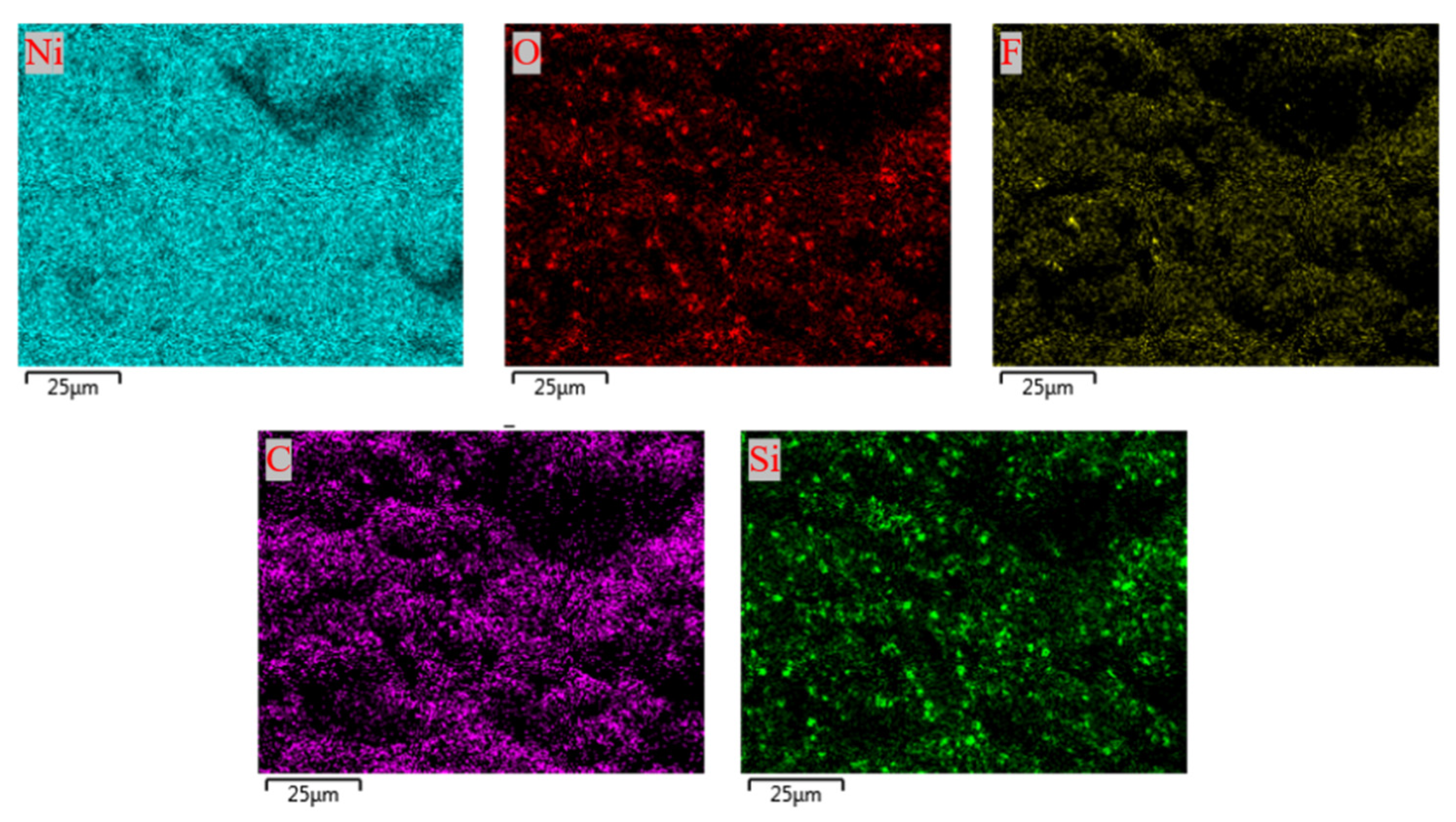
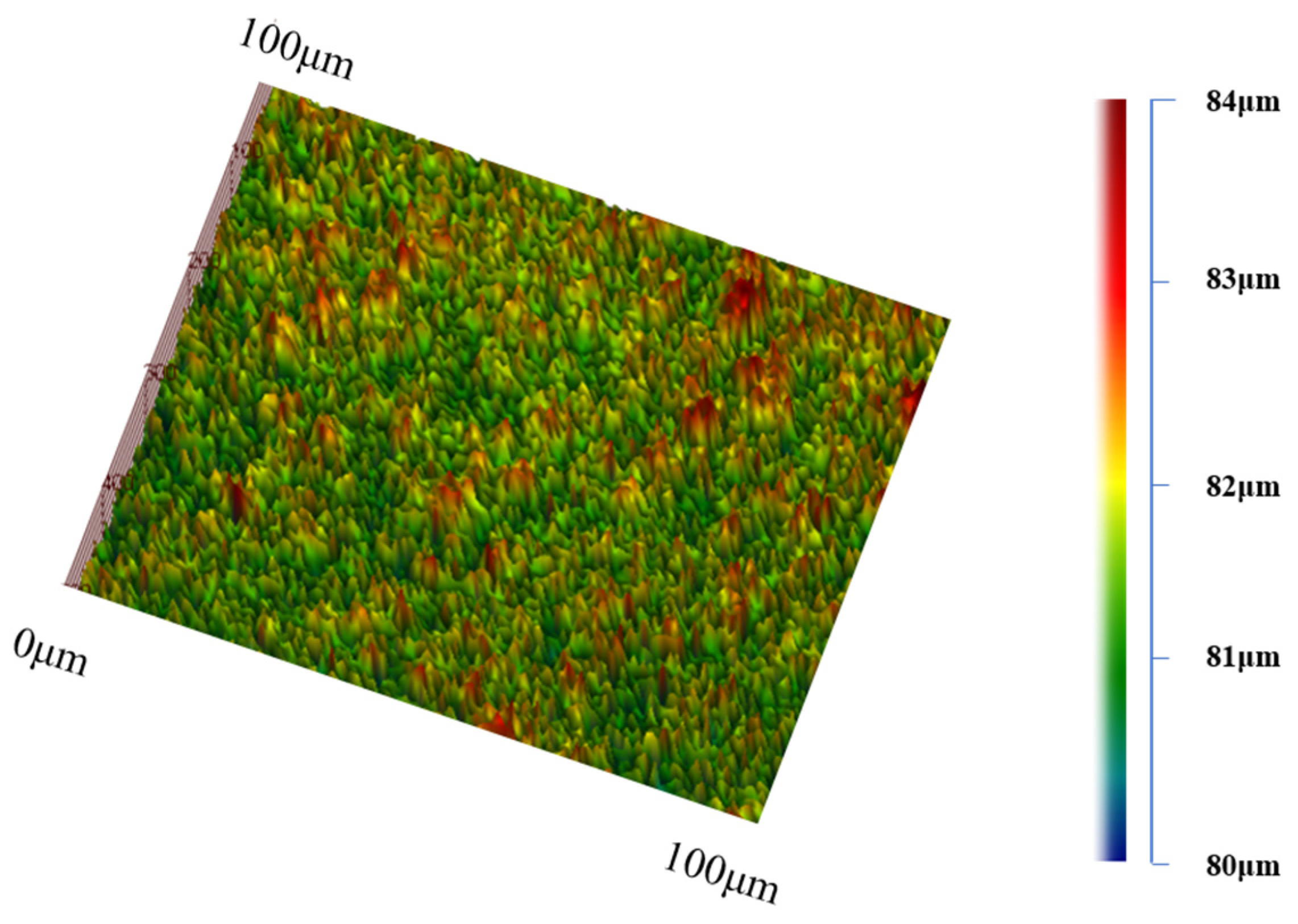
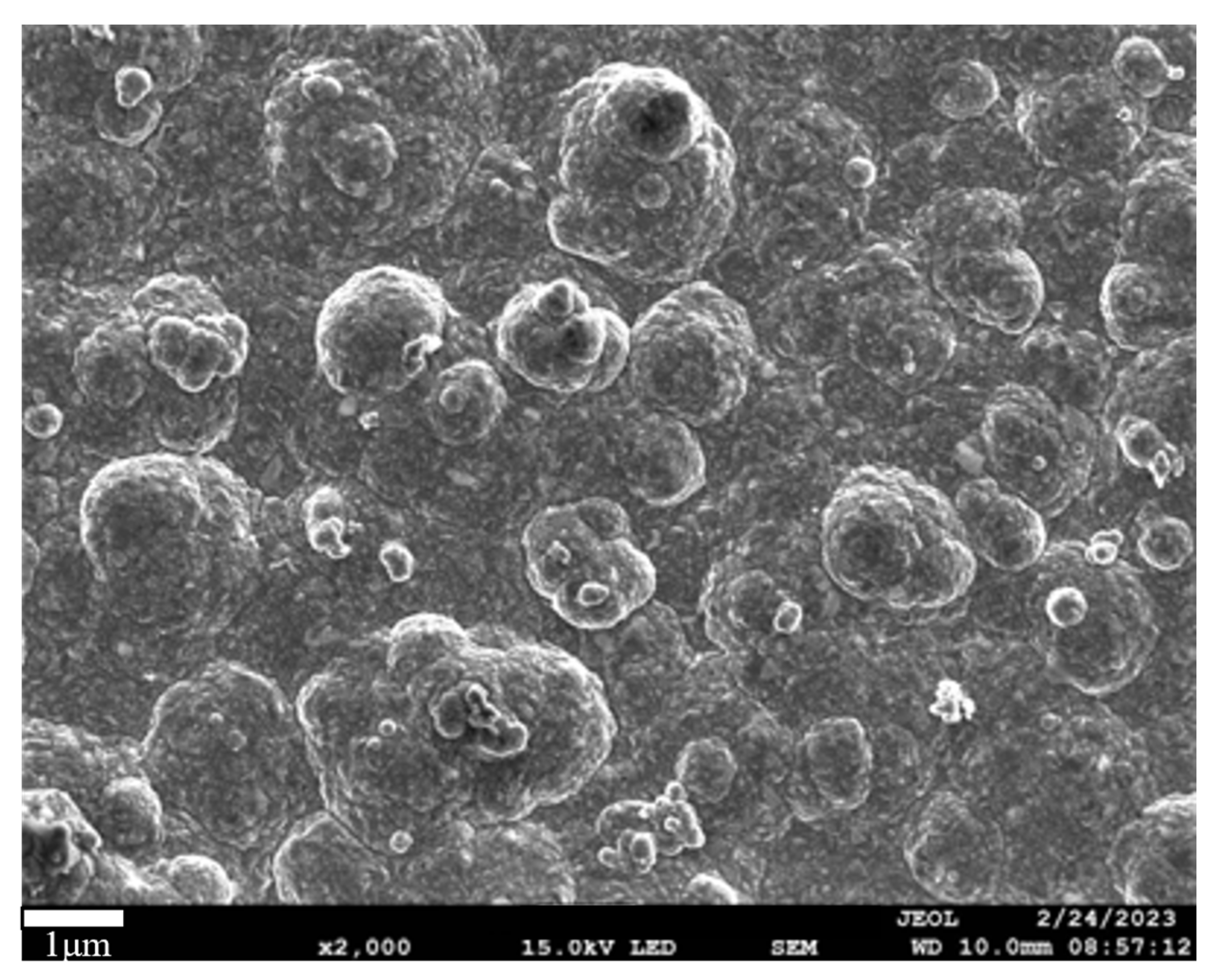
3.1. Effect of SiO2 Particle Concentration of Different Particle Sizes in the Plating Solution on the Coating

The water contact angle and oil contact angle of the composite coating at various concentrations of micro/nano silica particles were measured, and the results are shown in Figure 3 and Figure 4. At a concentration of 8 g/L of 20 nm SiO2 particles in the plating solution, without 1 μm SiO2 micron particles, the static contact angles of water and oil are 136° and 129°, respectively. The dynamic rolling angles for water and oil are 19° and 22°.
When the concentration of 20 nm SiO2 nanoparticles was adjusted to 6 g/L, and 1 μm SiO2 micron particles were added at 2 g/L, the static contact angles of water and oil increased to 159° and 151°, respectively, and the rolling angles approached 0°, demonstrating excellent superamphiphobic characteristics.
Conversely, reducing the concentration of 20 nm SiO2 nanoparticles to 2 g/L while increasing the concentration of 1 μm SiO2 micron particles to 6 g/L resulted in decreased amphiphobic performance. Further, at 8 g/L of 1 μm SiO2 micron particles without 20 nm SiO2 nanoparticles, the static contact angles of water and oil decreased to 141° and 135°, respectively. The dynamic rolling angles increased to 15° and 17°, indicating a loss of superamphiphobicity.
These findings highlight the critical role of particle size and concentration in achieving and maintaining superamphiphobic properties in the coating.
Figure 5 illustrates the microstructure of coatings formed by different concentrations of silica particles. In Figure 5a, when the concentration of 20 nm SiO2 nanoparticles is 8 g/L without 1 μm SiO2 micron particles, the surface morphology shows a large number of uniformly distributed nano-sized SiO2 particles. However, the absence of micron-sized particles results in an overall smooth coating surface that fails to form a micro/nano dual-scale structure, leading to only general amphiphobic performance.
In Figure 5b, at a nanoparticle concentration of 6 g/L and a micron particle concentration of 2 g/L, the surface morphology reveals deep ravines and peaks formed between the micron particles. Figure 6 presents a partially enlarged view of Figure 5b, highlighting how silica particles of both sizes serve as adsorption sites for the crystallization and growth of nickel metal. On the surface of these particles, nickel ions form smaller-scale spike-like structures, and numerous densely arranged nanoparticles populate the ravines between the micron protrusions, creating a micro/nano dual-scale structure that enhances the coating’s amphiphobic ability. At this point, the WCA and OCA are at their maximum. In Figure 5c, with a further reduction in the concentration of 20 nm SiO2 nanoparticles, the surface morphology shows a decrease in nano-scale protrusions, leading to slightly reduced surface roughness and decreased amphiphobic properties.
In Figure 5d, at a micron particle concentration of 6 g/L, the surface morphology indicates fewer nano-level protrusions and more micron-level particles, resulting in a smoother surface and a decline in amphiphobic performance. Finally, Figure 5e depicts the surface morphology when the concentration of micron particles is 8 g/L without any nanoparticles. The coating surface features large clusters and irregularly agglomerated nano-ions. The number of protrusions formed by nano-silica is significantly reduced, causing a slight reduction in superhydrophobicity, with the static contact angles of water and oil dropping to 141° and 135°, respectively.
The superamphiphobicity of the coatings is obtained only when the concentration of 20 nm sized SiO2 in the plating solution is 6 g/L and the concentration of 1 µm sized SiO2 is 2 g/L. These observations highlight the importance of balancing the concentration of nano- and micron-sized particles to achieve optimal micro/nano dual-scale structures, which are crucial for superior amphiphobic performance in the coatings. SiO2 particles are the key factor in achieving the superhydrophobic/superoleophobic properties.
The superamphiphobic coatings obtained at the optimal micro/nanoparticle concentrations (6 g/L for 20 nm SiO2 and 2 g/L for 1 μm SiO2) will be used in subsequent experiments. To determine the elemental composition and content of the Ni-SiO2 superamphiphobic coating, an EDS test was conducted. The results, shown in Figure 7, reveal that the coating comprises five elements: Ni, F, Si, C, and O. Nickel is the most abundant element at 41.03%. Silicon accounts for 6.81%, and oxygen is 9.45%, indicating the successful deposition of silica particles on the coating surface. The atomic percentages of fluorine and carbon are 23.19% and 19.52%, respectively, demonstrating that AC-FAS effectively modified the composite coating surface. Figure 8 presents the distribution map of each element on the Ni-SiO2 coating surface. The uniform distribution of various elements suggests that both the metal ions in the plating solution and the deposition process of SiO2 on the electrode surface during electrodeposition are relatively uniform. This uniformity enhances the coating’s performance and quality. Figure 9 shows the 3D morphology of the Ni- SiO2 superamphiphobic coating surface. The coating surface features protrusions of varying scales, representing the micro/nano dual-scale structure formed by embedded silica particles and nickel. The average surface roughness (Ra) of the coating is 2.23 μm. Figure 10 displays the cross-sectional scanning electron microscope image of the Ni-SiO2 superamphiphobic coating. The thickness of the coating is 14.2 μm, with no noticeable pinholes, cracks, or other defects, indicating strong adhesion between the coating and the substrate.

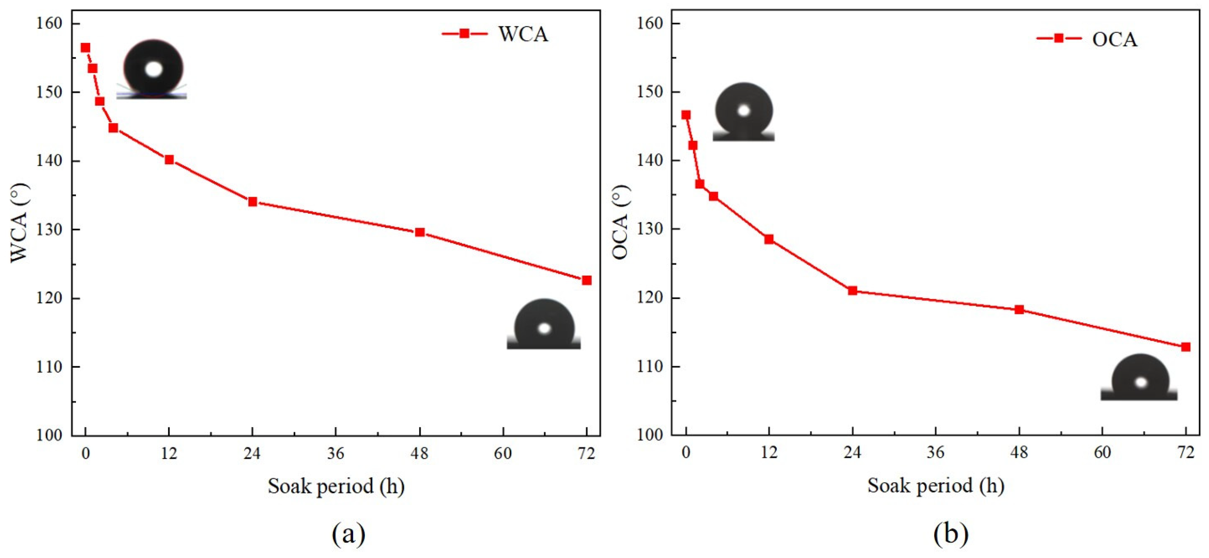
3.2. Chemical Stability of the Coating

The change in the contact angle of the Ni-SiO2 superamphiphobic coating in 3.5 wt.% NaCl solution over time is shown in Figure 11. After 1 h of immersion, the water and oil contact angles were 156° and 146°, respectively. When the immersion time was extended to 4 h, the water and oil contact angles decreased to 147° and 138°, respectively. The reduction in amphiphobicity can be attributed to the initial Cassie mode [36] contact between the coating and the corrosive solution. As immersion time increases, the solution gradually contacts the coating surface completely, transitioning to the Wenzel mode [37]. This shift, along with the adsorption of corrosive ions on the coating surface, disrupts the micro/nanostructure and increases surface energy, reducing the coating’s amphiphobicity [38]. Additionally, the corrosion damaged the micro/nanostructures, further altering the contact mode and decreasing hydrophobicity. After 72 h of immersion, the water and oil contact angles of the coating further decreased to 124° and 114°, respectively. Despite this reduction, the coating maintained hydrophobic and oleophobic properties, demonstrating strong chemical stability in the 3.5 wt.% NaCl solution.

3.3. Corrosion Resistance of the Coating

3.3.1. Polarization Curve Analysis
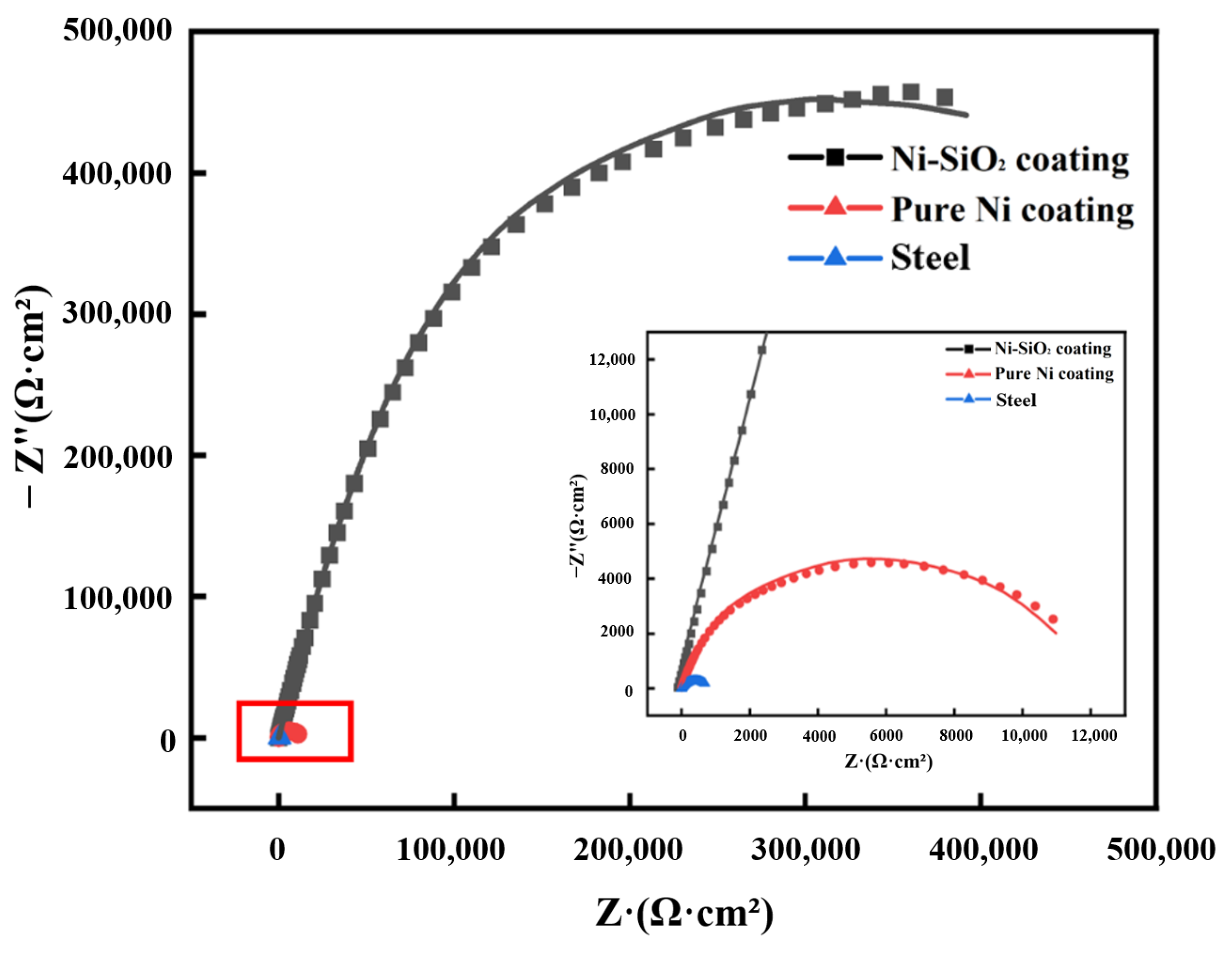
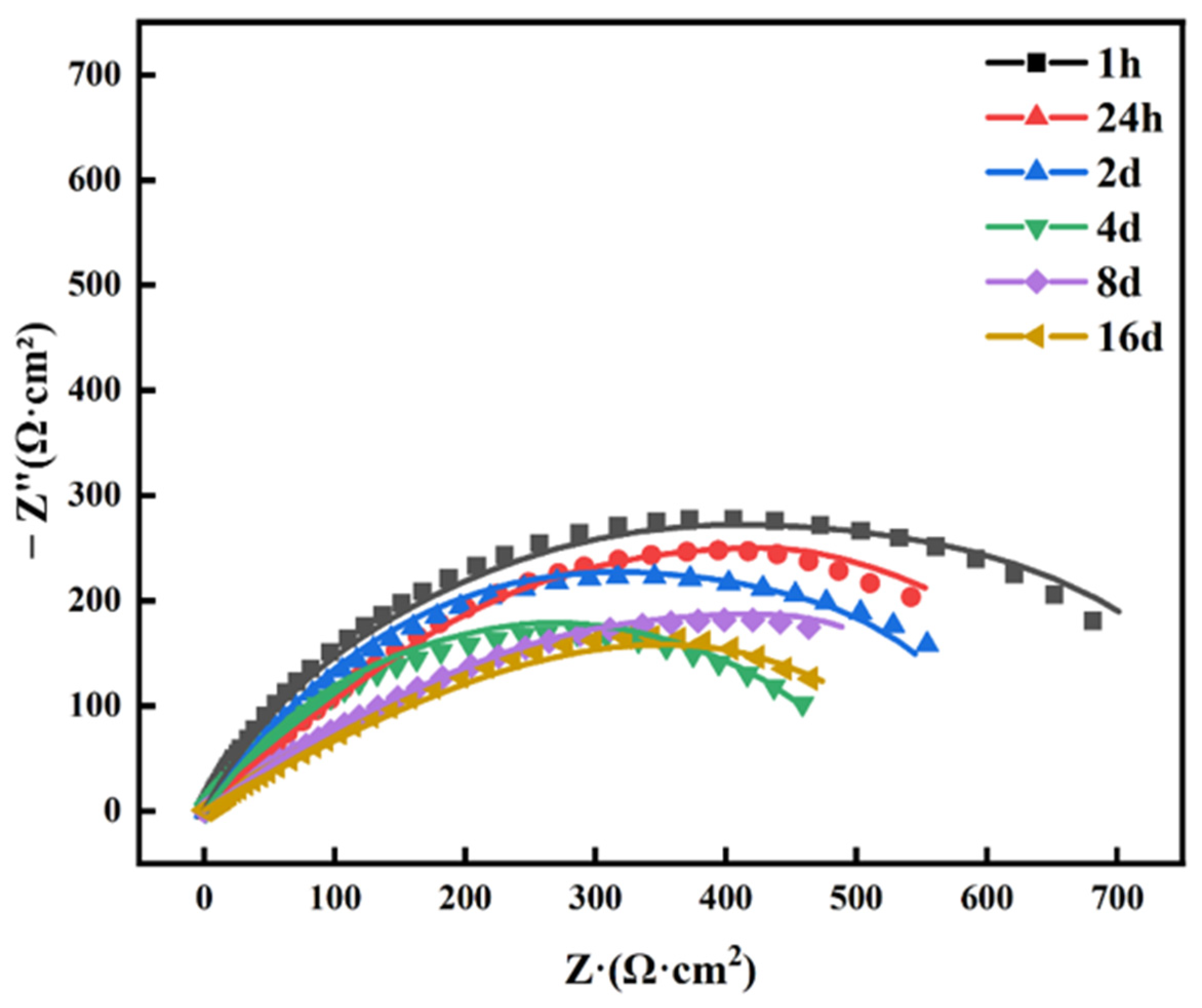
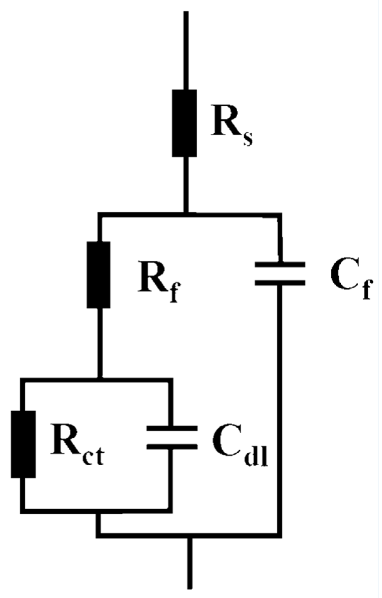
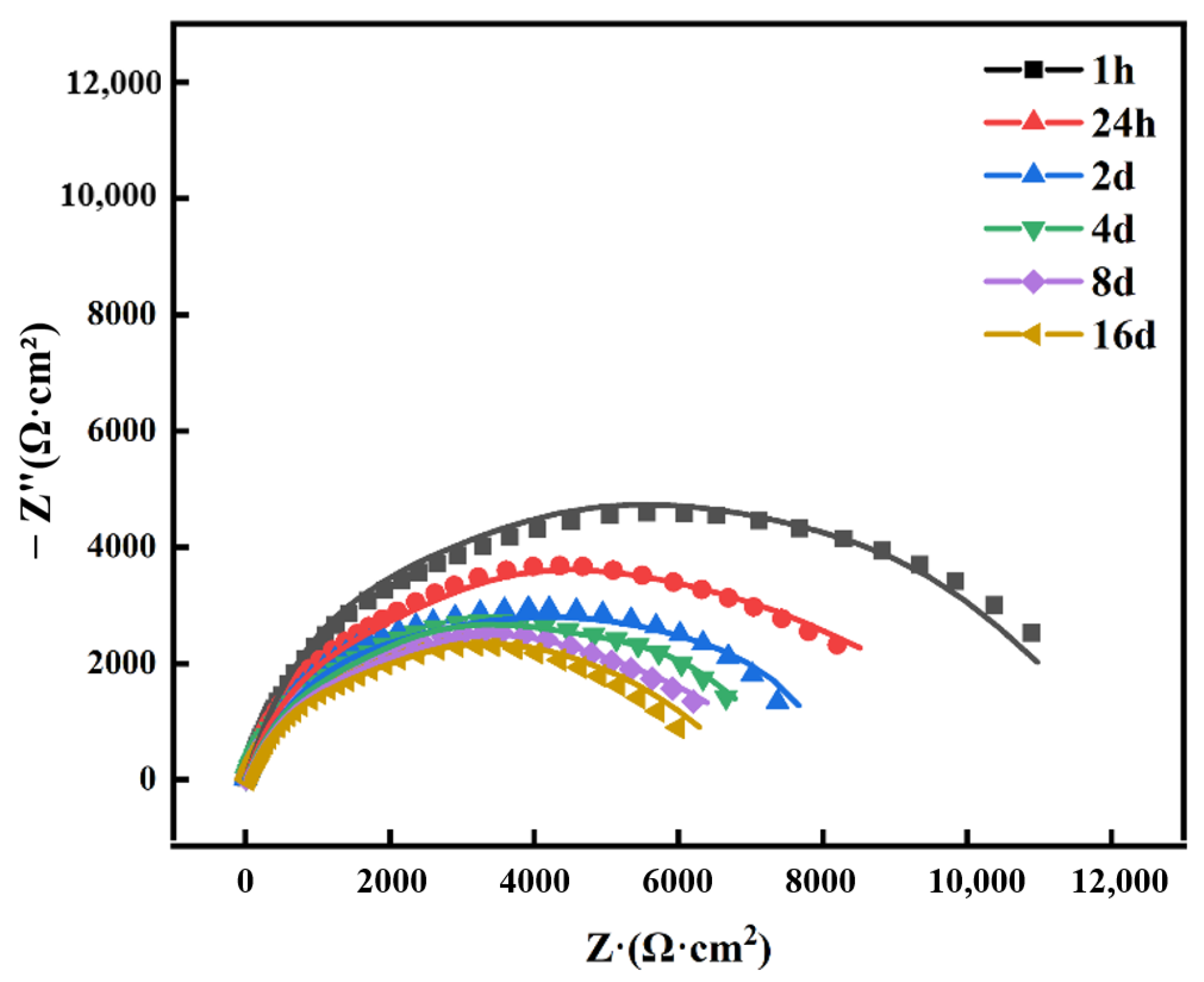
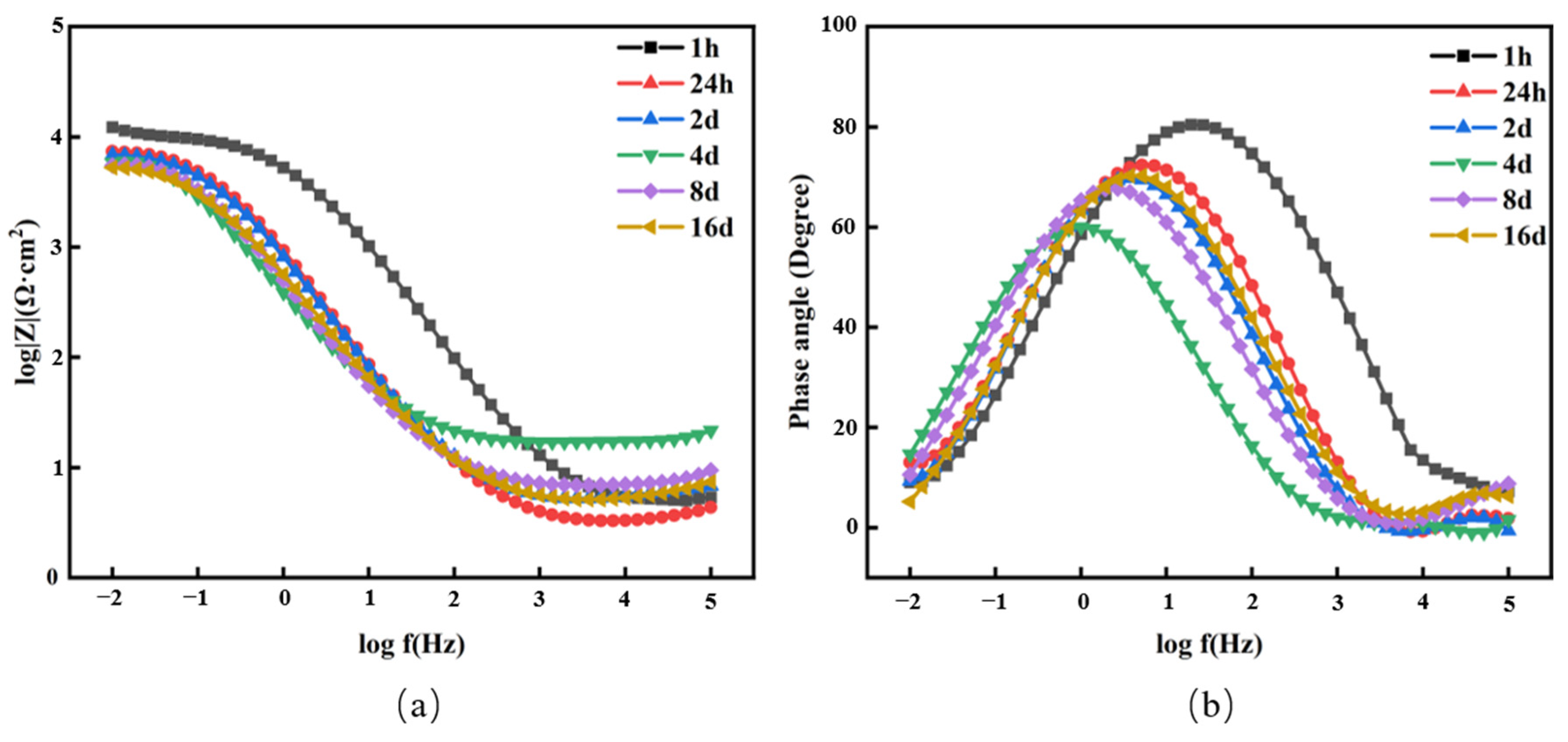
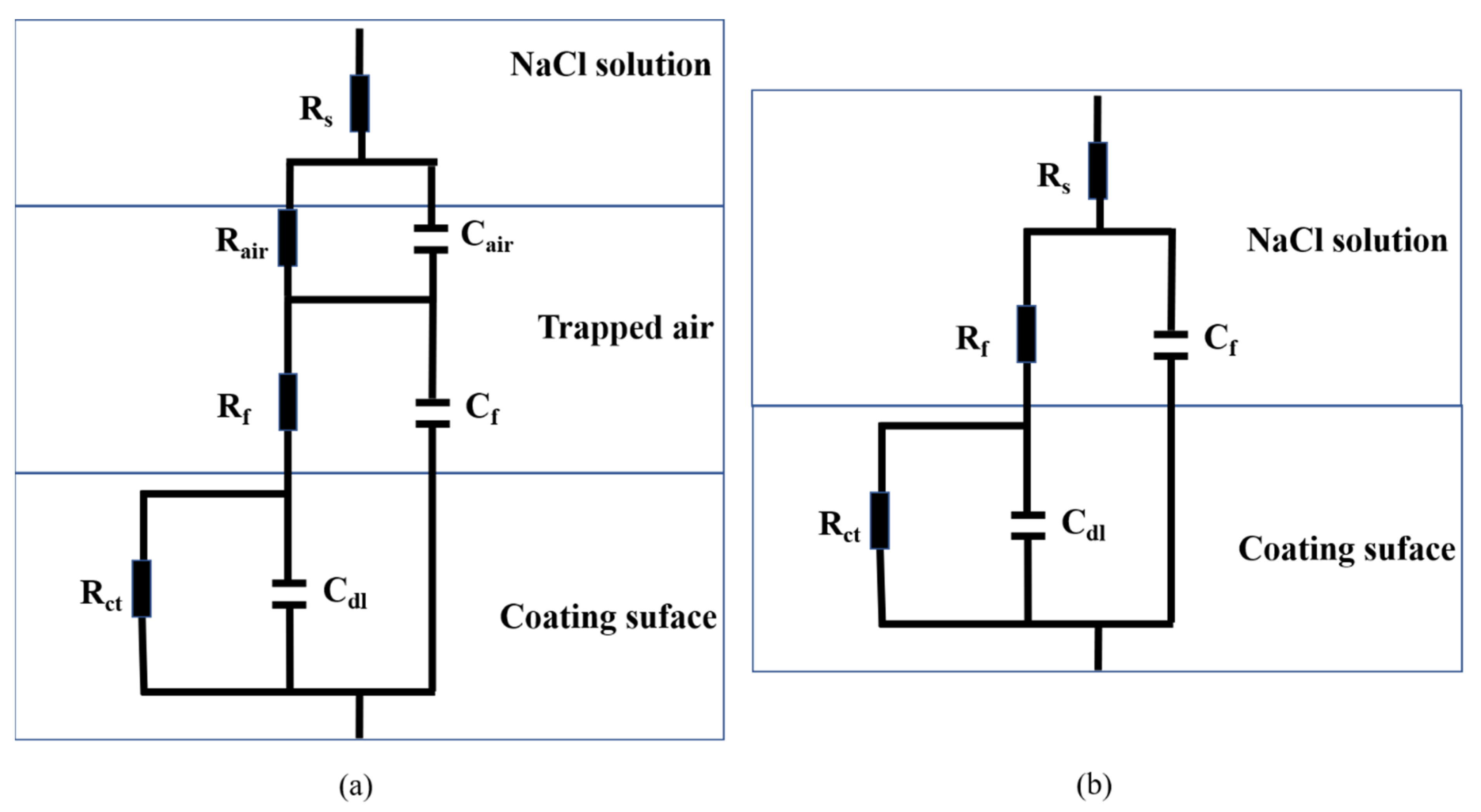
Figure 12 presents the potentiodynamic polarization curves of steel, the pure nickel coating, and the Ni-SiO2 superamphiphobic coating immersed in 3.5 wt.% NaCl solution for 30 min. The corrosion potential (Ecorr) and corrosion current density (icorr) of each sample were summarized in Table 4. Then, the corrosion efficiency of the pure nickel coating and superamphiphobic coating were calculated according to Equation (1). In the formula, icorr,sub and icorr,coated represent the corrosion current density of steel and coating, respectively.
η = i c o r r , s u b i c o r r , c o a t e d i corr , s u b × 100 %
The Ecorr of the nickel-plated sample is significantly positive, and the icorr is slightly reduced, indicating improved corrosion resistance. The inhibition efficiency η is only about 59.8%. In contrast, the Ni-SiO2 superamphiphobic coating exhibits the highest Ecorr and a corrosion current density that is two orders of magnitude lower than that of both the steel and pure nickel coating. The inhibition efficiency of the Ni-SiO2 superamphiphobic coating is exceptionally high at 98.9%, demonstrating its outstanding anti-corrosion performance. This significant improvement underscores the effectiveness of the superamphiphobic coating in protecting against corrosion in harsh environments.

3.3.2. EIS Analysis

The Nyquist plots of different samples after soaking in a corrosion medium for 0.5 h are shown in Figure 13. Clearly, the capacitive arc radius of the sample with the superhydrophobic coating was significantly larger than that of the bare carbon steel substrate and the nickel coating, a symbol of the excellent anti-corrosion effect.
Figure 14 and Figure 15 show the EIS of steel samples in 3.5 wt.% NaCl solution. During the electrochemical corrosion process, the anode undergoes an oxidation reaction, and the cathode undergoes an oxygen absorption reaction. After 16 days of immersion, significant yellow and black corrosion products were observed adhering to the surface of the steel.
To better understand the corrosion mechanism of steel in 3.5 wt.% NaCl solution, an equivalent circuit is constructed, as shown in Figure 16. Here, Rs represents solution resistance, Rf is the resistance of the corrosion product film on the steel surface, Rct denotes charge transfer resistance, and Cf and Cdl denote the capacitance of the corrosion product film and the double layer capacitance at the interface of steel and the solution, respectively. The fitting values of the AC impedance spectra of each circuit element are shown in Table 5. The charge transfer resistance of steel shows a decreasing trend with immersion time.
Figure 17 and Figure 18 are the AC impedance spectra of the pure nickel coating with time. The impedance spectrum of pure nickel coating was fitted using the equivalent circuit shown in Figure 19b, and the fitted values of the circuit elements are listed in Table 6. The overall trend shows a decrease in charge transfer resistance as the corrosive medium gradually alters the coating’s surface structure, indicating a gradual decline in corrosion resistance.
Figure 20 and Figure 21 show the Nyquist diagram and Bode diagram of the AC impedance spectrum of Ni-SiO2 superamphiphobic coating in 3.5 wt.% NaCl solution for different times. The Nyquist plot initially exhibits a significant capacitive arc resistance, attributed to the presence of an air interlayer on the coating’s surface during the early stages of soaking. By the 2nd day of immersion, this air interlayer dissipates, as indicated by a decrease in the phase angle peak to a single, narrower peak corresponding to a single time constant. By the 16th day, no new phase angle peak was observed, suggesting that the corrosive medium had not penetrated the interface between the coating and the metal substrate [39].
To elucidate the electrochemical behavior of Ni-SiO2, the corrosion process was divided into initial and late immersion stages, each described separately by the equivalent circuit shown in Figure 19. Table 7 presents the AC impedance spectrum fitting values for each circuit element. Notably, the initial air interlayer resistance peaked at approximately 105 ohms·cm2 after 1 h, suggesting significant corrosion inhibition during the initial period. However, as time increased, Rair decreased progressively, indicating air interlayer dissipation. Throughout the test period, the coating’s resistance remained significantly lower than the charge transfer resistance, highlighting the latter’s critical role in the corrosion process within the electric double layer.
This underscores the superior corrosion resistance of the Ni-SiO2 superamphiphobic coating, attributed to its micro/nano-structured surface creating air-filled grooves that hinder wetting and penetration by corrosive liquids [40].
To quantitatively assess corrosion resistance over time, the polarization resistance (Rp) of steel, pure nickel coating, and Ni-SiO2 superamphiphobic coating was calculated. Equation (2) calculates the polarization resistance of Ni-SiO2 superamphiphobic coating, while Equation (3) calculates the polarization resistance of steel and pure nickel coating:
R p = R a i r + R f + R c t
R p = R f + R c t
Table 8 presents the polarization resistance values for each sample at different times. Notably, the polarization resistance of Ni-SiO2 superamphiphobic coating remained high at 1.100 × 10⁷ Ω·cm2, indicating effective corrosion protection by the air interlayer on the coating surface. Even after 16 days, the polarization resistance remained at 8.398 × 10³ Ω·cm2, albeit showing a decreasing trend due to the formation of Ni(OH)2 during the corrosion process. This compound benefits from the micro/nano-bumps on the coating surface, providing numerous active sites for its growth and the formation of a passivation layer that further inhibits corrosion [41].
In conclusion, the Ni-SiO2 superamphiphobic coating exhibits exceptional corrosion resistance compared to steel and pure nickel coating. Its unique micro/nanostructure and air interlayer effectively prevent the penetration of corrosive media, providing long-term protection against corrosion.

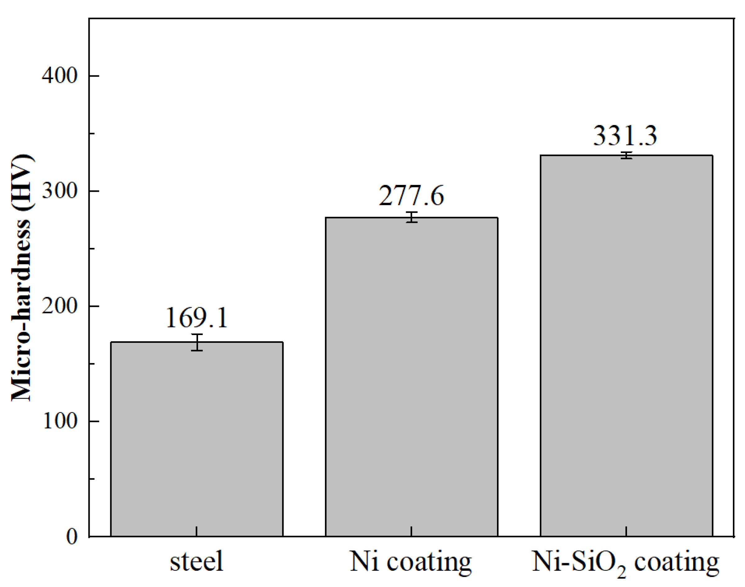
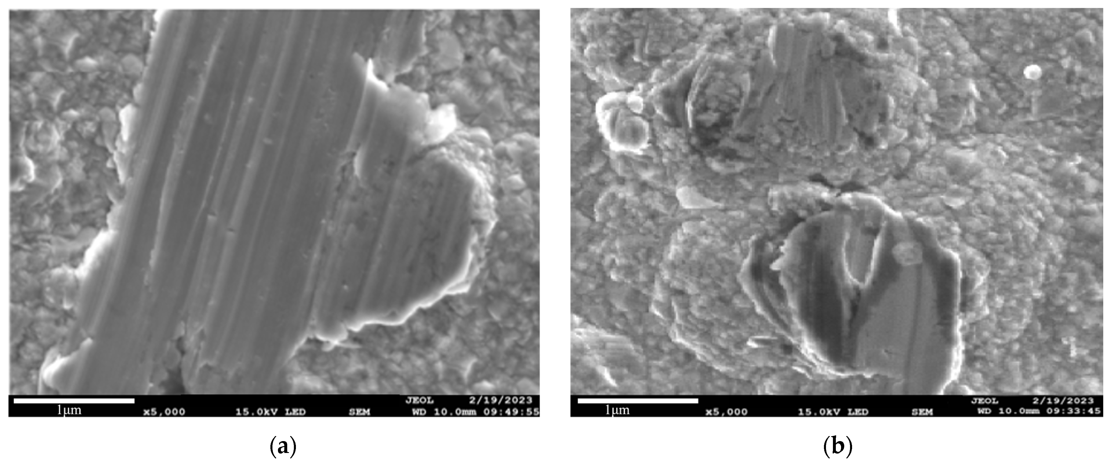
3.4. The Wear Resistance of the Coating

Figure 22 shows the Vickers hardness values of steel, pure nickel coating, and Ni-SiO2 superamphiphobic coating. The Ni-SiO2 coating exhibits the highest microhardness, approximately 1.2 times that of pure nickel coating and 1.96 times that of steel. This significant increase in microhardness is attributed to the inherent hardness of silica particles. The co-deposition of these particles with nickel enhances the overall hardness of the coating.
Figure 23, Figure 24 and Figure 25 depict the water–oil contact angle changes with friction distance, wear resistance, and scanning electron microscope (SEM) images after wear testing. The water–oil contact angle of the Ni-SiO2 superamphiphobic coating shows minimal change even after 400 cm of wear, maintaining its superamphiphobic properties. In contrast, the AC-FAS-modified pure nickel superhydrophobic coating loses its superhydrophobicity after 40 cm of wear, with the water static contact angle dropping sharply to 143°. SEM images reveal severe surface damage and wear marks on the pure nickel coating, whereas the Ni-SiO2 superamphiphobic coating shows minimal wear due to its high hardness and strong adhesion to the substrate. Although the tops of the micron-scale structures are abraded, the nanoscale structures and surface modifiers remain intact, resulting in significantly less abrasion of the superamphiphobic coating. The micro/nano dual-scale structure of the Ni-SiO2 coating remains preserved, maintaining its amphiphobic performance even after extended wear.

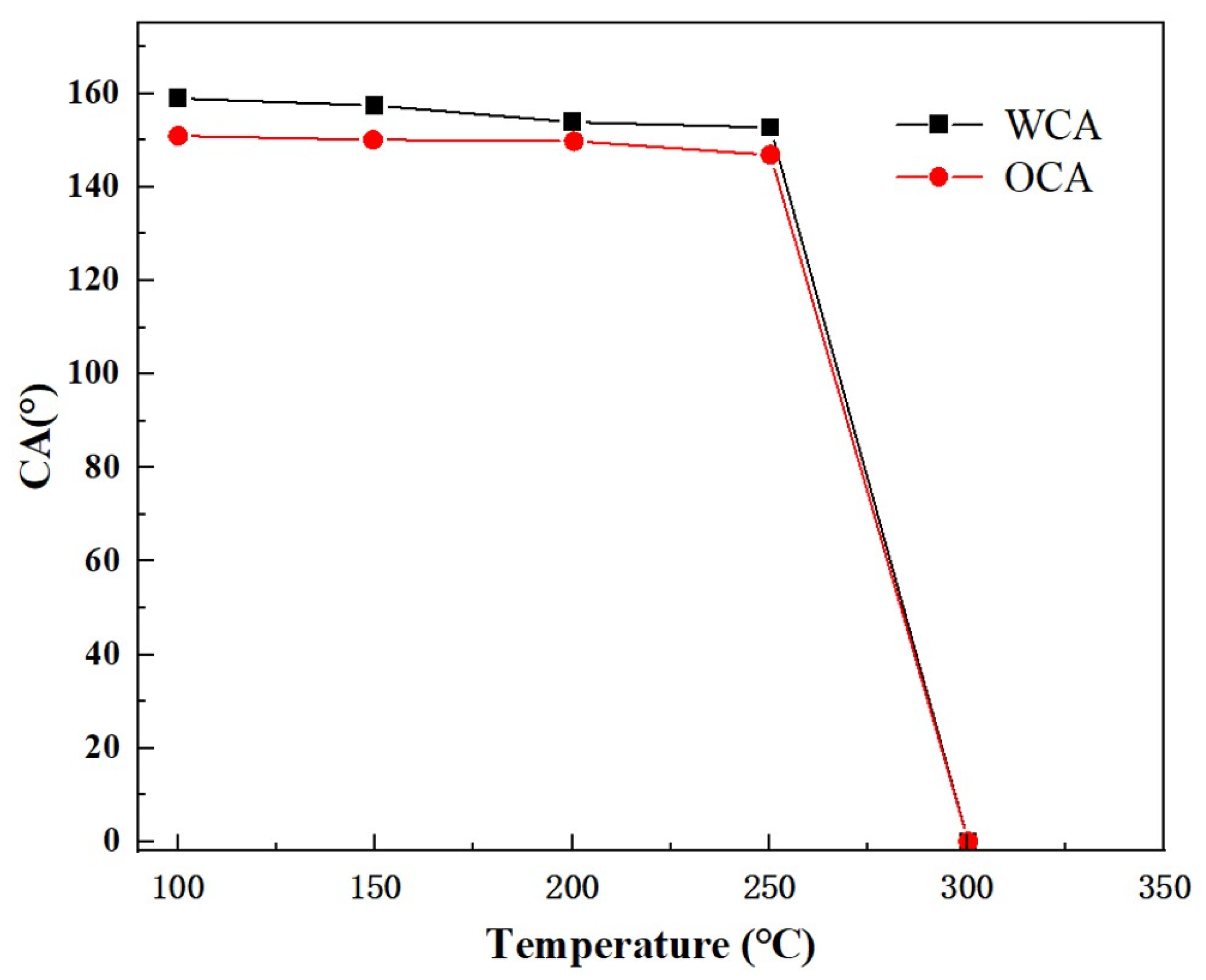
3.5. The High-Temperature Resistance of the Coating

Figure 26 demonstrates the static contact angles of water and oil on Ni-SiO2 superamphiphobic coatings at different temperatures. Up to 250 °C, the contact angles remain stable at 153° for water and 147° for oil, indicating robust superamphiphobic behavior where droplets maintain spherical shapes on the coating surface. However, at 300 °C, the coating transitions abruptly from a superamphiphobic state to a hydrophilic and lipophilic state, with water and oil droplets spreading fully on the surface. Figure 27’s SEM image confirms that high-temperature treatment at 300 °C does not compromise the surface morphology or integrity of the coating.
Figure 28 presents the results of energy-dispersive X-ray spectroscopy (EDS). Comparison with Figure 8 reveals that the percentage of fluorine (F) atoms on the coating surface undergoes a significant decrease after the high-temperature treatment at 300 °C. This reduction indicates the loss of the low-surface-energy fluorocarbon material (AC-FAS) from the coating surface. This is due to the boiling point of AC-FAS of about 300 °C; when the temperature was heated to 300 °C, AC-FAS began to evaporate; after losing the modification of AC-FAS, the surface energy of the coating rose sharply, leading to the conversion from superamphiphobic to hydrophilic and lipophilic properties.
In conclusion, the Ni-SiO2 superamphiphobic coating exhibits exceptional high-temperature stability, maintaining strong amphiphobic properties up to 250 °C. The coating’s high hardness and robust micro/nanostructure contribute to its superior wear resistance and durability under harsh environmental conditions.

4. Conclusions

A Ni-SiO2 superamphiphobic coating was prepared using composite electrodeposition. The optimal process was determined by adjusting the concentration of SiO2 particles in the plating solution to 6 g/L for 20 nm silica particles and 2 g/L for 1 μm silica particles. Electrodeposition was performed at a current density of 10 A/dm2 for 20 min, followed by heating in a fluorosilane solution at 80 °C for 3 h and curing in a drying oven at 115 °C for 1 h. The resulting coating exhibited excellent superamphiphobic properties, with contact angles for water and oil of 159° and 151°, respectively, and a rolling angle close to 0°.
The coating also demonstrated good chemical stability and corrosion resistance. Its short-term corrosion resistance in 3.5 wt.% NaCl solution was remarkable, with a corrosion current density two orders of magnitude lower than that of steel and pure nickel coating, and a corrosion efficiency of 98.9%. After 16 days of immersion in 3.5 wt.% NaCl solution, the polarization resistance of the coating remained 15.12 times that of steel and 1.27 times that of pure nickel coating, indicating that the corrosive medium did not penetrate the interface between the coating and the substrate.
Additionally, the coating exhibited a hardness of up to 331.3 HV. The coating shows good wear resistance and high-temperature resistance under the wear resistance test and high-temperature test.

Author Contributions

Conceptualization, J.L.; methodology, Z.W.; validation, X.X.; formal analysis, S.W.; investigation, J.L. and S.W.; resources, X.X.; data curation, S.T.; writing—original draft preparation, S.T.; writing—review and editing, G.C.; visualization, Z.W.; supervision, G.C.; funding acquisition, J.L. All authors have read and agreed to the published version of the manuscript.

Funding

This work was supported by the China Scholarship Council (No. 202306450157).

Data Availability Statement

The raw data supporting the conclusions of this article will be made available by the authors on request.

Conflicts of Interest

Author Shuaihua Wang was employed by the company CNPC Offshore Engineering Qingdao Co., Ltd. (CPOE). Author Zhiyao Wan was employed by the company Offshore Oil Engineering (Qingdao) Co., Ltd. The remaining authors declare that the research was conducted in the absence of any commercial or financial relationships that could be construed as a potential conflict of interest.

References

  1. Fihri, A.; Bovero, E.; Al-Shahrani, A.; Al-Ghamdi, A.; Alabedi, G. Recent progress in superhydrophobic coatings used for steel protection: A review. Colloids Surf. A Physicochem. Eng. Asp. 2017, 520, 378–390. [Google Scholar] [CrossRef]
  2. Karapanagiotis, I.; Manoudis, P.N. Superhydrophobic and superamphiphobic materials for the conservation of natural stone: An overview. Constr. Build. Mater. 2022, 320, 126175. [Google Scholar] [CrossRef]
  3. Abu Jarad, N.; Imran, H.; Imani, S.M.; Didar, T.F.; Soleymani, L. Fabrication of Superamphiphobic Surfaces via Spray Coating; a Review. Adv. Mater. Technol. 2022, 7, 2101702. [Google Scholar] [CrossRef]
  4. She, Z.; Li, Q.; Wang, Z.; Li, L.; Chen, F.; Zhou, J. Novel Method for Controllable Fabrication of a Superhydrophobic CuO Surface on AZ91D Magnesium Alloy. ACS Appl. Mater. Interfaces 2012, 4, 4348–4356. [Google Scholar] [CrossRef]
  5. Shang, W.; Chen, B.; Shi, X.; Chen, Y.; Xiao, X. Electrochemical corrosion behavior of composite MAO/sol–gel coatings on magnesium alloy AZ91D using combined micro-arc oxidation and sol–gel technique. J. Alloys Compd. 2009, 474, 541–545. [Google Scholar] [CrossRef]
  6. Liu, Y.; Liu, J.; Tian, Y.; Zhang, H.; Wang, R.; Zhang, B.; Zhang, H.; Zhang, Q. Robust Organic–Inorganic Composite Films with Multifunctional Properties of Superhydrophobicity, Self-Healing, and Drag Reduction. Ind. Eng. Chem. Res. 2019, 58, 4468–4478. [Google Scholar] [CrossRef]
  7. Han, Z.; Feng, X.; Guo, Z.; Niu, S.; Ren, L. Flourishing Bioinspired Antifogging Materials with Superwettability: Progresses and Challenges. Adv. Mater. 2018, 30, 1704652. [Google Scholar] [CrossRef]
  8. Guo, F.; Wen, Q.; Peng, Y.; Guo, Z. Multifunctional hollow superhydrophobic SiO2 microspheres with robust and self-cleaning and separation of oil/water emulsions properties. J. Colloid Interface Sci. 2017, 494, 54–63. [Google Scholar] [CrossRef]
  9. Wu, Y.; Zhao, M.; Guo, Z. Multifunctional superamphiphobic SiO2 coating for crude oil transportation. Chem. Eng. J. 2018, 334, 1584–1593. [Google Scholar] [CrossRef]
  10. Si, Y.; Yang, F.; Guo, Z. Bio-inspired one-pot route to prepare robust and repairable micro-nanoscale superhydrophobic coatings. J. Colloid Interface Sci. 2017, 498, 182–193. [Google Scholar] [CrossRef]
  11. Zhang, X.; Si, Y.; Mo, J.; Guo, Z. Robust micro-nanoscale flowerlike ZnO/epoxy resin superhydrophobic coating with rapid healing ability. Chem. Eng. J. 2017, 313, 1152–1159. [Google Scholar] [CrossRef]
  12. Li, D.; Guo, Z. Stable and self-healing superhydrophobic MnO2@fabrics: Applications in self-cleaning, oil/water separation and wear resistance. J. Colloid Interface Sci. 2017, 503, 124–130. [Google Scholar] [CrossRef]
  13. Wen, G.; Gao, X.; Tian, P.; Zhong, L.; Wang, Z.; Guo, Z. Modifier-free fabrication of durable and multifunctional superhydrophobic paper with thermostability and anti-microbial property. Chem. Eng. J. 2018, 346, 94–103. [Google Scholar] [CrossRef]
  14. Si, Y.; Guo, Z. Eco-friendly functionalized superhydrophobic recycled paper with enhanced flame-retardancy. J. Colloid Interface Sci. 2016, 477, 74–82. [Google Scholar] [CrossRef] [PubMed]
  15. Wang, F.; Guo, Z. Facile fabrication of ultraviolet light cured fluorinated polymer layer for smart superhydrophobic surface with excellent durability and flame retardancy. J. Colloid Interface Sci. 2019, 547, 153–161. [Google Scholar] [CrossRef] [PubMed]
  16. Wang, F.; Wang, D.; Guo, Z. Highly fluorinated F-APP-TiO2 particle with hierarchical core-shell structure and its application in multifunctional superamphiphobic surface: Mechanical robustness, self-recovery and flame retardancy. J. Colloid Interface Sci. 2020, 560, 777–786. [Google Scholar] [CrossRef]
  17. Wu, Y.; Zhao, M.; Guo, Z. Robust, heat-resistant and multifunctional superhydrophobic coating of carbon microflowers with molybdenum trioxide nanoparticles. J. Colloid Interface Sci. 2017, 506, 649–658. [Google Scholar] [CrossRef]
  18. Wen, G.; Guo, Z. Nonflammable superhydrophobic paper with biomimetic layered structure exhibiting boiling-water resistance and repairable properties for emulsion separation. J. Mater. Chem. A Mater. Energy Sustain. 2018, 6, 7042–7052. [Google Scholar] [CrossRef]
  19. Qu, M.; Yang, X.; Peng, L.; Liu, L.; Yang, C.; Zhao, Z.; Liu, X.; Zhang, T.; He, J. High reliable electromagnetic interference shielding carbon cloth with superamphiphobicity and environmental suitability. Carbon 2021, 174, 110–122. [Google Scholar] [CrossRef]
  20. Si, Y.; Chen, L.; Yang, F.; Guo, F.; Guo, Z. Stable Janus superhydrophilic/hydrophobic nickel foam for directional water transport. J. Colloid Interface Sci. 2018, 509, 346–352. [Google Scholar] [CrossRef]
  21. Liang, X.; Guo, Z. Mechano-adjusted anisotropic surface for manipulating water droplets. Chem. Eng. J. 2020, 395, 125110. [Google Scholar] [CrossRef]
  22. Si, Y.; Dong, Z. Bioinspired Smart Liquid Directional Transport Control. Langmuir 2020, 36, 667–681. [Google Scholar] [CrossRef] [PubMed]
  23. Qing, Y.; Hu, C.; Yang, C.; An, K.; Tang, F.; Tan, J.; Liu, C. Rough Structure of Electrodeposition as a Template for an Ultrarobust Self-Cleaning Surface. ACS Appl. Mater. Interfaces 2017, 9, 16571–16580. [Google Scholar] [CrossRef] [PubMed]
  24. Liao, K.; Zhu, J. Fabrication of superamphiphobic surface on Cu substrate via a novel and facile dip coating method. Colloids Surf. A Physicochem. Eng. Asp. 2022, 639, 128379. [Google Scholar] [CrossRef]
  25. Geng, Z.; He, J. An effective method to significantly enhance the robustness and adhesion-to-substrate of high transmittance superamphiphobic silica thin films. J. Mater. Chem. A 2014, 2, 16601–16607. [Google Scholar] [CrossRef]
  26. Wang, C.F.; Chiou, S.F.; Ko, F.H.; Chou, C.T.; Lin, H.C.; Huang, C.F.; Chang, F.C. Fabrication of Biomimetic Super-Amphiphobic Surfaces Through Plasma Modification of Benzoxazine Films. Macromol. Rapid Commun. 2006, 27, 333–337. [Google Scholar] [CrossRef]
  27. Sheen, Y.; Huang, Y.; Liao, C.; Chou, H.; Chang, F. New approach to fabricate an extremely super-amphiphobic surface based on fluorinated silica nanoparticles. J. Polym. Sci. Part B Polym. Phys. 2008, 46, 1984–1990. [Google Scholar] [CrossRef]
  28. Deng, X.; Mammen, L.; Butt, H.-J.; Vollmer, D. Candle Soot as a Template for a Transparent Robust Superamphiphobic Coating. Science 2012, 335, 67–70. [Google Scholar] [CrossRef]
  29. Wang, H.; Chi, G.; Jia, Y.; Yu, F.; Wang, Z.; Wang, Y. A novel combination of electrical discharge machining and electrodeposition for superamphiphobic metallic surface fabrication. Appl. Surf. Sci. 2020, 504, 144285. [Google Scholar] [CrossRef]
  30. Li, Q.; Xia, F.; Liu, G.; Yao, L. Microstructure and Properties of Jet Pulse Electrodeposited Ni-TiN Nanocoatings. J. Mater. Eng. Perform. 2022, 31, 8823–8829. [Google Scholar] [CrossRef]
  31. Jin, P.; Sun, C.; Zhang, Z.; Zhou, C.; Williams, T. Fabrication of the Ni-W-SiC thin film by pulse electrodeposition. Surf. Coat. Technol. 2020, 392, 125738. [Google Scholar] [CrossRef]
  32. Cheng, X.; He, Y.; Song, R.; Li, H.; Liu, B.; Zhou, H.; Yan, L. Study of mechanical character and corrosion properties of La2O3 nanoparticle reinforced Ni-W composite coatings. Colloids Surf. A Physicochem. Eng. Asp. 2022, 652, 129799. [Google Scholar] [CrossRef]
  33. Yan, L.; Yan, S.; He, Y.; He, Y.; Li, H.; Song, R.; Zhou, H.; Cheng, X. Preparation, corrosion resistance and mechanical properties of electroless Ni-B/α-ZrP composite coatings. Colloids Surf. A Physicochem. Eng. Asp. 2022, 654, 130132. [Google Scholar] [CrossRef]
  34. Qin, B.; Zhou, S.; Chen, H.; Wang, M. Superior corrosion and wear resistance of AZ91D Mg alloy via electrodeposited SiO2–Ni-based composite coating. Mater. Chem. Phys. 2022, 283, 126001. [Google Scholar] [CrossRef]
  35. Shakoor, R.A.; Waware, U.S.; Kahraman, R.; Popelka, A.; Yusuf, M.M. Corrosion Behavior of Electrodeposited Ni-B Coatings Modified with SiO2 Particles. Int. J. Electrochem. Sci. 2017, 12, 4384–4391. [Google Scholar] [CrossRef]
  36. Cassie, A.B.D.; Baxter, S. Wettability of porous surfaces. Trans. Faraday Soc. 1944, 40, 546–551. [Google Scholar] [CrossRef]
  37. Wenzel, R.N. Resistance of solid surfaces to wetting by water. Trans. Faraday Soc. 1936, 28, 988–994. [Google Scholar] [CrossRef]
  38. Patankar, N.A. Transition between superhydrophobic states on rough surfaces. Langmuir 2004, 20, 7097–7102. [Google Scholar] [CrossRef]
  39. Zhao, H.; Ding, J.; Liu, P.; Yu, H. Boron nitride-epoxy inverse “nacre-like” nanocomposite coatings with superior anticorrosion performance. Corros. Sci. 2021, 183, 109333. [Google Scholar] [CrossRef]
  40. Hu, C.; Xie, X.; Ren, K. A facile method to prepare stearic acid-TiO2/zinc composite coating with multipronged robustness, self-cleaning property, and corrosion resistance. J. Alloys Compd. 2021, 882, 160636. [Google Scholar] [CrossRef]
  41. Xing, S.; Wang, L.; Jiang, C.; Liu, H.; Zhu, W.; Ji, V. Influence of Y2O3 nanoparticles on microstructures and properties of electrodeposited Ni–W–Y2O3 nanocrystalline coatings. Vacuum 2020, 181, 109665. [Google Scholar] [CrossRef]
Figure 1. Schematic diagram of electrodeposition double-electrode system.
Metals 14 01047 g001
Figure 2. Schematic illustration of the abrasion test.
Metals 14 01047 g002
Figure 3. The WCA and WSA of coatings at different concentrations of micro/nanoparticles. The error bars indicate standard deviations.
Metals 14 01047 g003
Figure 4. The OCA and OSA of coatings at different concentrations of micro/nanoparticles. The error bars indicate standard deviations.
Metals 14 01047 g004
Figure 5. SEM morphology of composite coatings under different particle size–particle concentration ratios: (a) 8/0, (b) 6/2, (c) 4/4, (d) 2/6, (e) 0/8.
Metals 14 01047 g005
Figure 6. The SEM morphology of composite coatings at a concentration ratio of 6/2 of nanoscale particles to micron-sized particles.
Metals 14 01047 g006
Figure 7. EDS diagram of superamphiphobic coatings.
Metals 14 01047 g007
Figure 8. The distribution of elements on the surface of superamphiphobic coatings.
Metals 14 01047 g008
Figure 9. The three-dimensional topography of the superamphiphobic coating’s surface.
Metals 14 01047 g009
Figure 10. Cross-sectional morphology of superamphiphobic coatings.
Metals 14 01047 g010
Figure 11. The change in the contact angle of the Ni-SiO2 superamphiphobic coating with immersion time: (a) water contact angle, (b) oil contact angle.
Metals 14 01047 g011
Figure 12. Polarization curves of Steel, Ni coating, and Ni-SiO2 superamphiphobic coating.
Metals 14 01047 g012
Figure 13. Nyquist plots of bare substrate, Ni coating, and Ni-SiO2 superamphiphobic coating.
Metals 14 01047 g013
Figure 14. Nyquist plots of steel immersed for different times.
Metals 14 01047 g014
Figure 15. Bode plots of steel immersed for different times. (a) Frequency–impedance plot; (b) frequency–phase angle plot.
Metals 14 01047 g015
Figure 16. Equivalent circuit of steel in solution.
Metals 14 01047 g016
Figure 17. Nyquist plots of pure Ni coating immersed for different times.
Metals 14 01047 g017
Figure 18. Bode plots of pure Ni coating immersed for different times. (a) Frequency–impedance plot; (b) frequency–phase angle plot.
Metals 14 01047 g018
Figure 19. Equivalent circuits of Ni-SiO2 superamphiphobic coating in 3.5 wt.% NaCl solution. (a) initial time, (b) failure time.
Metals 14 01047 g019
Figure 20. Nyquist plots of Ni-SiO2 superamphiphobic coating immersed for different times.
Metals 14 01047 g020
Figure 21. Bode plots of Ni-SiO2 superamphiphobic coating immersed for different times. (a) Frequency–impedance plot; (b) frequency–phase angle plot.
Metals 14 01047 g021
Figure 22. A comparison of the hardness of steel, Ni coating, and Ni-SiO2 superamphiphobic coating.
Metals 14 01047 g022
Figure 23. Contact angle of pure Ni superhydrophobic coating under different wear distance: (a) water contact angle; (b) oil contact angle.
Metals 14 01047 g023
Figure 24. Contact angle of Ni-SiO2 composite superamphiphobic coating under different wear distance: (a) water contact angle; (b) oil contact angle.
Metals 14 01047 g024
Figure 25. Surface morphology of samples after wear: (a) pure Ni coating; (b) Ni-SiO2 composite superamphiphobic coating.
Metals 14 01047 g025
Figure 26. The contact angle of the Ni-SiO2 superamphiphobic coating at different temperatures.
Metals 14 01047 g026
Figure 27. The SEM morphology of the Ni-SiO2 superamphiphobic coating after high-temperature treatment at 300 °C.
Metals 14 01047 g027
Figure 28. EDS diagram of Ni-SiO2 superamphiphobic coating after high temperature treatment at 300 °C.
Metals 14 01047 g028
Table 1. Composition and content of bath.
Reagent NameChemical FormulaConcentration
Nickel sulfateNiSO4·6H2O (Sinopharm Chemical Reagent Co., Ltd., Shanghai, China)240 g/L
Nickel chlorideNiCl2·6H2O (Sinopharm Chemical Reagent Co., Ltd., Shanghai, China)40 g/L
Boric acidH3BO3 (Sinopharm Chemical Reagent Co., Ltd., Shanghai, China)35 g/L
Sodium lauryl sulfateC12H25SO4Na (Sinopharm Chemical Reagent Co., Ltd., Shanghai, China)0.15 g/L
20 nm SiO2SiO2 (Lavasi (Beijing) New Material Technology Co., Ltd., Beijing, China)0, 2, 4, 6, 8 g/L
1 μm SiO2SiO2 (Lavasi (Beijing) New Material Technology Co., Ltd., Beijing, China)0, 2, 4, 6, 8 g/L
Table 2. Composition of different SiO2 micro/nanoparticles.
Test20 nm SiO2 Concentration (g/L)1 μm SiO2 Concentration (g/L)
180
262
344
426
508
Table 3. Electrodeposition process parameters.
Experimental ParametersNumerical Setting
Temperature (°C)50
pH4.6
Mixing speed (r/min)150
Electrodeposited current density (A/dm2)10
Electrodeposition time (min)20
Table 4. Electrochemical parameters after fitting the polarization curves of different samples.
Sample NameEcorr
(mVSCE)
icorr
(A·cm−2)
βa
(mV·dec−1)
βc
(mV·dec−1)
η
Steel−513.297.62 × 10−583.61011.3--
Pure nickel coating−466.313.06 × 10−5206.9132.659.8%
Ni-SiO2 superamphiphobic coating−360.978.32 × 10−7277.4103.398.9%
Table 5. The parameters of the equivalent circuit elements of steel with time.
TimeRf
(Ω·cm2)
Cf
(F·cm−2)
Rct
(Ω·cm2)
Cdlχ2
Y0−1·cm−2·sn)n
1 h8.3123.224 × 10−4900.11.371 × 10−30.6883.77 × 10−4
24 h10.5613.301 × 10−4877.54.009 × 10−30.7203.53 × 10−3
2 days5.6883.325 × 10−4730.52.932 × 10−30.7331.12 × 10−4
4 days6.0972.432 × 10−4573.92.188 × 10−30.7011.45 × 10−3
8 days5.9331.401 × 10−4772.44.177 × 10−30.5193.87 × 10−4
16 days12.0322.256 × 10−4583.14.202 × 10−30.6283.51 × 10−4
Table 6. The parameters of the equivalent circuit elements of freshly prepared pure Ni coating with time.
TimeRf
(Ω·cm2)
Cf
(F·cm−2)
Rct
(Ω·cm2)
Cdlχ2
Y0−1·cm−2·sn)n
1 h25.612.451 × 10−512,9114.323 × 10−50.7363.31 × 10−3
24 h36.297.026 × 10−590178.145 × 10−50.6975.15 × 10−3
2 days44.517.309 × 10−582161.378 × 10−40.7454.01 × 10−4
4 days33.978.991 × 10−581332.891 × 10−40.7333.23 × 10−4
8 days29.068.635 × 10−575141.941 × 10−40.7897.92 × 10−4
16 days30.127.157 × 10−570561.033 × 10−40.7518.73 × 10−4
Table 7. The parameters of the equivalent circuit elements of Ni-SiO2 superamphiphobic coating with time.
TimeRair
Ω·cm2
Cair
F·cm−2
Rf
Ω·cm2
Cf
F·cm−2
Rct
Ω·cm2
Cdlχ2
Y0−1·cm−2·sn)n
1 h3.270 × 1053.021 × 10−529.192.406 × 10−66.826 × 1052.537 × 10−50.7034.91 × 10−3
1 day1.532 × 1054.488 × 10−528.174.153 × 10−62.121 × 1051.505 × 10−50.7393.22 × 10−4
2 days1.231 × 1054.617 × 10−533.515.961 × 10−61.307 × 1053.022 × 10−50.6216.81 × 10−4
4 days----38.121.158 × 10−512,1034.165 × 10−50.6084.51 × 10−4
8 days----36.381.235 × 10−598712.315 × 10−50.5996.44 × 10−4
16 days----35.611.375 × 10−589628.188 × 10−50.6088.09 × 10−4
Table 8. The polarization resistance of steel, pure Ni coating, and Ni-SiO2 superamphiphobic coating (Ω·cm2).
TimeSteelPure Nickel CoatingNi-SiO2 Superamphiphobic Coating
1 h908.411.291 × 1041.100 × 107
24 h888.069.053 × 1033.653 × 105
2 days736.198.216 × 1032.238 × 105
4 days580.008.133 × 1031.214 × 104
8 days778.337.514 × 1039.907 × 103
16 days595.137.056 × 1038.997 × 103
Disclaimer/Publisher’s Note: The statements, opinions and data contained in all publications are solely those of the individual author(s) and contributor(s) and not of MDPI and/or the editor(s). MDPI and/or the editor(s) disclaim responsibility for any injury to people or property resulting from any ideas, methods, instructions or products referred to in the content.

