Review

High-Cycle Fatigue Performance of Laser Powder Bed Fusion Ti-6Al-4V Alloy with Inherent Internal Defects: A Critical Literature Review

Mechanical Systems Engineering, EMPA-Swiss Federal Laboratories for Materials Science and Technology, CH-8600 Duebendorf, Switzerland
*
Author to whom correspondence should be addressed.
Metals 2024, 14(9), 972; https://doi.org/10.3390/met14090972
Submission received: 31 July 2024 / Revised: 14 August 2024 / Accepted: 21 August 2024 / Published: 27 August 2024
(This article belongs to the Section Additive Manufacturing)

Abstract

:
The inadequate fatigue performance of Laser Powder Bed Fusion (L-PBF) Ti-6Al-4V alloy, primarily due to intrinsic defects, poses a significant challenge for industrial applications. Internal defects often serve as initiation sites for fatigue cracks, significantly impacting the fatigue life of L-PBF Ti-6Al-4V components. Accurate evaluation of the role of internal defects in fatigue performance and quantitative analysis of influential parameters are crucial for guiding optimal L-PBF manufacturing design. This study aims to critically review recent notable contributions focusing on high-cycle fatigue (HCF) in these alloys, with many of the presented insights being easily transferred to other types of AM alloys. Efforts have been made to identify correlations between fatigue life at various stages and critical internal defects. Key aspects, including microstructure and post-processing treatments, and their effects on HCF have been thoroughly analyzed. The findings enhance the scientific understanding of fatigue performance of L-PBF Ti-6Al-4V alloy and open new avenues for future research.

1. Introduction

Additive manufacturing (AM) of Ti-6Al-6V alloy has gained significant importance in various industries, including aerospace, automotive, healthcare, and spare parts manufacturing [1,2,3,4,5,6]. This advanced manufacturing technique offers numerous advantages such as the elimination of melding restrictions, the ability to achieve complex geometries through topological optimization, and cost reduction, while minimizing material waste [7].
Among the various AM techniques, Laser Powder Bed Fusion (L-PBF) has emerged as a prominent method for fabricating Ti-6Al-4V alloy, driven by compelling advantages. First and foremost, L-PBF allows for unparalleled design freedom, enabling complex geometries and intricate structures over conventional manufacturing techniques [8,9]. It can produce parts with higher dimensional accuracy and smoother surface finishes over the other types of AM technologies. This capacity is particularly beneficial for industries that require precise and intricate designs to meet stringent performance and weight specifications, such as aerospace and biomedical components. Second, L-PBF provides the ability to tailor the microstructure and mechanical properties of Ti-6Al-4V components through precise control of the processing parameters and enables the optimization of mechanical properties for high-performance applications [10,11]. Moreover, L-PBF operates at a lower temperature than Electron Beam Powder Bed Fusion (E-PBF), which reduces residual stresses and preserves the desired material properties [12].
Nevertheless, the inadequate fatigue performance of L-PBF Ti-6Al-4V alloy, particularly in high-cycle fatigue (HCF) and the very high cycle fatigue (VHCF) regimes, remains a major challenge for its industrial application, especially for fatigue critical components such as jet engines, gas turbines, and various airframe structures [1,2,3,13,14]. Unlike low-cycle fatigue (LCF), HCF is concerned with the endurance of materials under low-stress, high-cycle conditions commonly encountered in aerospace, automotive, and biomedical applications [15,16]. L-PBF intrinsic defects can significantly influence the fatigue life properties by acting as stress concentrators that initiate and propagate fatigue cracks [12,17]. Unlike surface roughness, which can be relatively easily eliminated through post-surface treatments such as machining or polishing, internal defects present a more significant challenge. Certain internal defects, such as gas porosities, cannot be easily removed by post-processing methods [18] unless hot isostatic pressing (HIP) is applied. Furthermore, current advancements in manufacturing techniques are not expected to completely avoid these internal defects in the foreseeable future [19,20].
The fatigue performance problem of AM Ti-6Al-4V and other metal alloys have been addressed by a number of literature efforts in recent years. Table 1 summarizes the representative published review works in the last five years, as well as their main focused topics and suggested future research. Liu and Shin (2019) [21] provided an overall review on AM Ti-6Al-4V alloy. Pegues et al. (2020) [22] and Molaei et al. (2020) [23] reviewed the correlation between AM processing and defects, and between defects and mechanical performance, respectively. Sanaei and Fatemi (2021) [24] have overviewed the fatigue performance problem for general AM metal alloys. Wang et al. (2024) [25] reviewed machine learning (ML) models for fatigue life predictions of AM metal alloys. Key fatigue-performance-associated aspects have been addressed, particularly in porosity [26,27,28,29], microstructure [27,30,31], HCF [32], and post-processing treatments [26,27,33,34].
Table 1. Reflection of representative published review works in recent years.
Author (s)Topics CoveredFuture Direction Highlighted
Liu and Shin 2019 [21]Overall overview of DED, EPBF and L-PBF processing and inherent defects including porosities, and residual stress, microstructure, tensile and fatigue properties and relevant influential factors in a nutshell.Not available (NA)
Pegues et al., 2020 [22] Molaei et al., 2020 [23]Part I reviewed the correlation between AM processing (including post-processing) and the microstructure and defects; part II reviewed the correlation between the different types of fatigue behaviors and microstructure and defects.NA
Teixeira et al., 2020 [33]Heat treatment’s role on residual stresses, microstructure, and mechanical properties including ductility, fatigue life, and hardness.
  • Find the optimal balance point on different mechanical properties by heat treatment.
  • Further investigations on the residual stresses.
Sanaei and Fatemi 2021 [24]Different types of intrinsic AM defects and their effects on the fatigue performance.
  • Small crack growth properties for AM metals under different processing and post-processing conditions.
  • The selection of critical defect characteristics.
  • Further studies on crystal plasticity finite element (CPFE) and FEA which involves defect and microstructure characterization.
  • Multiscale modelling to bridge material science and solid mechanics to understand the role and modelling of defects in fatigue performance.
Singla et al., 2021 [26]Overview of different types of intrinsic L-PBF defects and different types of post-processing treatments’ effects on defects and mechanical behavior.
  • Recommendation on the printing parameters including hatch space, scan spend, laser power.
  • More research on defects induced by insufficient energy input (e.g., LOF, balling, etc.) is needed.
  • More investigations regarding the heat treatment are needed, especially different temperature ranges.
  • Quantitative investigations on HIP parameters.
  • Combinations of post-processing treatments.
Kan et al., 2022 [28]The effects of porosities on the mechanical properties of L-PBF metal alloys.NA
Nguyen et al., 2022 [30]Microstructure of AM Ti-6Al-4V including the microstructure and the defects’ role in the fatigue properties.
  • The need for more efficient manufacturing with lower costs.
  • Autonomous printing without human supervision.
  • Further improvement of the ductility and fatigue life.
Jamhari et al., 2023 [29,31]Heat treatment and HIP on the microstructure, porosities and mechanical properties of L-PBF Ti-6Al-4V alloy.
  • Further study on the efficacy of heat treatment parameters in improving processing-induced issues such as residual stress.
  • Further heat-treatment optimization.
  • The impact of different HIP parameters on the surface quality and mechanical characteristics of L-PBF Ti-6Al-4V components.
Hasan Tusher and Ince 2023 [32]Overview of the state of the art on the fatigue behavior of L-PBF Ti-6Al-4V alloy including L-PBF processing parameters, various types of defects, post-processing, and fatigue properties.
  • The role of post-processing heat treatments and HIP treatments, considering the geometrical configurations and load ratio.
  • Investigate the mechanism involved in each post-processing on the fatigue properties.
  • Further quantitative study on the temperature and pressure of HIP treatment.
Wang et al., 2024 [25]Review of different machine learning algorithms and their application in the fatigue life of AM parts
  • Amount of accessible data and challenge to generate a large enough number of training samples.
  • Difficult to identify fatigue data as a learning target for supervised learning. Therefore, researchers from AM, ML and the material background must collaborate closely.
  • Understanding both the feature engineering of ML and the physical mechanism in AM.
While different AM metal alloys encounter similar challenges and share certain research overlaps, their unique properties often preclude direct comparison and application of findings across different materials. L-PBF Ti-6Al-4V exhibits a distinct microstructure, surface finish, residual stress, and internal defects compared to those manufactured via other types of AM technologies, which leads to different crack initiation and early stage growth behavior. This complexity is further compounded when considering different metal alloys produced by various AM techniques, each presenting unique challenges and characteristics.
This study conducts a critical review focused on the fatigue performance of L-PBF Ti-6Al-4V alloy, specifically addressing internal defects within the HCF regime. It also considers key related aspects such as post processing treatments, microstructure, and residual stresses, excluding other types of additive manufacturing processes, different defect types, LCF, and static mechanical properties unless specifically mentioned. The goal is to provide a comprehensive understanding of recent research advancements in HCF performance of L-PBF Ti-6Al-4V alloy, thereby offering a foundation for future investigations aimed at enhancing fatigue performance.
In our review effort, SCOPUS was searched using key words and their synonyms, and forward and backward snowballing techniques were employed; research in line with the topic was selected and then manually filtered. Following the introduction, Section 2 discusses the issues of internal defects, their impact on fatigue performance from various perspectives, and the evolution of fatigue cracks at different stages. Section 3 and Section 4 review critical factors related to microstructure and post-processing treatments, respectively. Section 5 reviews ML models of predicting fatigue life of AM Ti-6Al-4V alloy. Finally, Section 6 addresses the main conclusions and outlines perspectives for future research.

2. The Internal Defects Problem of L-PBF Ti-6Al-4V

The existing literature has identified more than five types of internal defects, including lack of fusion (LOF), entrapped gas pores, keyholes, α-phase facets, and small cracks. The morphologies and formation causes of these defects are extensively detailed in previous reviews and the open literature [24,26] and will not be reiterated here.
This section focuses on two predominant types of internal defects: entrapped gas pores and LOF (illustrated in Figure 1), for three primary reasons. First, these defects are inherent to L-PBF Ti-6Al-4V alloy and are challenging to eliminate through process optimization or standard post-processing. Second, they are the most frequently observed defects from which fatigue cracks originate. Third, they are the most extensively studied in the literature. This section also examines the critical aspects of fatigue life performance—fatigue crack initiation and propagation, highlighting their associated factors. Other defects such as keyholes and α-phase facets have been discussed as well.

2.1. The Role of Internal Defects on the Fatigue Performance

Unlike conventional manufactured titanium alloys [35,36,37] such as wrought, the predominant fatigue failure mechanism of L-PBF Ti-6Al-4V alloy originates from surface or internal defects, rather than α-phases. To explore the impact of internal defects on fatigue performance, numerous experimental studies have been conducted, with findings summarized in Table 2. These experiments reveal clear correlations between the porosity fraction, as well as the location, size, and morphology of internal defects, and fatigue failure mechanisms. Notably, a higher porosity fraction typically results in a shorter fatigue life, as illustrated by the stress–fatigue life (S–N) curve in Figure 2. This increase in porosity raises the likelihood of larger internal defects [38], which predominantly contribute to reduced fatigue life [39]. Specifically, larger defects—though not necessarily the largest—are commonly the initiation sites for cracks [40]. A threshold value of approximately 0.2 mm for the square root of projected area ( a r e a ) is suggested as critical for internal defects [41]. Furthermore, the shape of internal defects significantly influences fatigue performance [18].
The location of internal defects plays a dominant role in the fatigue performance of L-PBF Ti-6Al-4V parts [41]. Defects are prone to be produced in the subsurface areas of near-net-shape AM parts [38], due to imperfect connections between contour scanning and matrix scanning. According to statistics, approximately 85–90% of internal defects are located within 200 µm beneath the free surface [40]. This contributes to findings that 92% of specimen failures originate from surface or subsurface defects, even when the porosity fraction is low [42].
Table 2. Experimental studies on the fatigue performance of L-PBF Ti-6Al-4V alloys with internal defects.
No.Author (s)Defect TypeMain Research Objective
1Günther et al., 2017 [43]Gas pore, LOFHCF and VHCF
2Becker et al., 2020 [44]PorosityCrack propagation
3Waddell et al., 2020 [45]Gas pore, LOFCrack propagation
4Hu et al., 2020 [42]Gas pore, LOFCorrelate the defect population with the fatigue life
5Du et al., 2021 [38]Gas pore, LOFProcessing parameters’ influence on the S–N curve
6Pessard et al., 2021 [46]Artificial surface defect, gas pore, LOFFatigue strength and critical defect size, 30 um
7Xu et al., 2021 [47]Gas pore, LOFMicrostructure, vacuum situation, microstructure
8Akgun et al., 2022 [40]Gas poreCrack initiation and propagation
9Chi et al., 2022 [48]Artificial surface defect, gas pore, LOFS–N curve
10Gao et al., 2022 and 2023 [18,49]Keyhole, Gas pore, LOFS–N curve, fatigue life
11Bhandari and Gaur 2023 [50]Gas pore, LOFCorrelation between post-processing and fatigue performance
12Mancisidor et al., 2023 [51]Gas porePost-processing
13Moquin et al., 2023 [41]Gas pore, LOFMicrostructure, correlation of volumetric energy densities with fatigue performance
14Önder et al., 2023 [52]Gas pore, LOFPost-processing
15Qu et al., 2023 [53]Gas pore, LOFCoupling effects of microstructure and internal defects
16Meng et al., 2023 [54]Porosity, surface defectMulti-crack initiation and propagation, image-based monitoring
Quantitatively correlating a subsurface defect with its embedded specimen’s fatigue performance is essential. Hu et al. (2020) [39] classified a subsurface defect as a surface crack if its minimum distance from the surface is less than a r e a . They defined the effective a r e a as including both the original area and the area between the defect and the free surface to calculate the stress intensity factor (SIF). However, this definition not only expands the considered area but also incorporates the Y factor typically used for surface cracks. This approach may be inappropriate as it could lead to an overestimation of the SIF. The Y factor should range from 0.5 for internal defects to 0.65 for surface defects [55].
Experimental investigations may yield subjective conclusions about the role of internal defects due to limited observations and data availability. In contrast, numerical analysis, specifically FEA, provides a cost-effective means to resolve disputes through comprehensive FE results and detailed analysis. FEA enables the modelling and analysis of internal defects varying in size, location, and morphology [55,56], as detailed in Table 3. It is important to note that the studies listed are not restricted to L-PBF Ti-6Al-4V alloy, as the FEA methodologies are applicable across different types of additive manufacturing processes and metal alloys because they exhibit significant similarities.
There are two common FE approaches: the global analysis [57,58] and the individual analysis [55,56]. Both methods require an FE model that is converted from a volumetric model originally created using X-ray micro-computerized tomography (µCT) scans. The key difference lies in the focus of the analysis—global analysis examines all internal defects collectively, while individual analysis targets specific local defects.
Global analyses focus on identifying all detectable internal defects within an entire component or a specified volume [58]. Generally, this type of analysis is effective in pinpointing critical defects likely to initiate fatigue cracks. Such assessments are typically based on locally distributed stress and strain results, or parameters derived from them, such as SCF, around the defects. This approach enhances our understanding of how the geometry of internal defects—such as size, location, and morphology—affects fatigue performance. However, analyzing many defects within a component simultaneously incurs significant computational costs due to the need for detailed meshing across numerous elements, which can limit its practical application. Moreover, while SCF-based methods may indicate defect criticality, they do not directly predict the fatigue performance of a component.
Table 3. Available numerical studies on AM metal parts for internal defects including different material and AM processing methods.
No.AuthorDefect TypeMaterialAM ProcessNumerical ApproachesFatigue
Criterion
1Siddique et al., 2015 [59]Gas poresAlSi12L-PBFFEASCF
2Wan et al., 2016 [60]Gas poresTi-6Al-4V-Multiscale, FEAStiffness, S–N curve
3Biswal et al., 2018 [56]Gas poresTi-6Al-4VL-PBFFEASCF, SWT
4Lukhi et al., 2018 [61]Micro voidNodular cast iron-Micromechanical, FEAStress, strain
5Biswal et al., 2019 [57]Gas poresTi-6Al-4VWAAMGraphic analysis, FEASCF, S–N curve
6Dinh et al., 2020 [62]Gas porosity and surface roughnessTi-6Al-4VL-PBFFEAnlSWT
7Hu et al., 2020 [39]Gas pores, LOFTi-6Al-4VL-PBFFEA, EXPNASGRO method
8Wang and Su 2021 [63]Gas pores316L steelL-PBFFEASCF
9Lauterbach et al., 2021 [58]Gas poresMetal-Immersed-Boundary-FEAVon Mises stress
10Pessard et al., 2021 [46]Surface defects, sub-surface defectTi-6Al-4VL-PBFFEASCF
11Li et al., 2022 [64]LOFTi-6Al-4VL-PBFFEASCF
12Xie et al., 2021 [65]Gas pores, LOFAl-Mg4.5 MnWAAMFEAVon Mises stress, SCF
13Shao et al., 2023 [66]Crack from poreTi-6Al-4VL-PBFFEACrack propagation
14Li et al., 2024 [55]LOFTi-6Al-4VL-PBFIndividual analysis3D average SWT, SIF, irregular crack propagation
Note: SCF represents the stress concentration factor; SWT is the Smith-Watson-Topper (SWT) criterion; nlSWT is a modified non-local 2D SWT criterion.
A prevailing view is that the fatigue performance of an AM component is largely determined by the most critical defect, from which the primary crack initiates and ultimately leads to failure [67,68]. A recent study monitored cracks initiation and propagation in L-PBF Ti-6Al-4V alloy during fatigue tests through periodical µCT scanning, as shown in Figure 3. The study indicated that multiple cracks could initiate and propagate simultaneously within one specimen, whereas one or two dominant cracks grew significantly faster than others in one specimen, ultimately leading to the specimen’s final fracture [54].
The approach of evaluating fatigue life of L-PBF Ti-6Al-4V alloy is thus twofold: first, identify the most critical defect; second, evaluate the fatigue performance based on this defect. For entrapped gas pores, simplified FE models such as manually modelled spheres or spheroids are often used due to their regular shapes and smooth surfaces. Biswal et al. (2019) [57] substituted the X-ray µCT scanned gas pore near the free surface with a quarter spherical model in FEA (see Figure 4c), and the resulting SCF closely matched those calculated using the original scanned model. This methodology has also been applied in a parametric study of gas pores, considering variables such as aspect ratio, proximity to the free surface, and hemispherical surface defects [56]. The study further indicated that the size of an internal gas pore has a minimal impact on the SCF, a conclusion supported by subsequent research on LOF defects [64]. In a related study, Wang and Su (2021) [63] analyzed stress concentration in irregularly shaped porosity, finding that the maximum stress concentration was strongly related to the largest projected area, corroborating the Murakami method [69], and was also influenced by the local shape of the defect.
Several researchers observed that LOFs were significantly more detrimental than entrapped gas pores as they often led to considerable shorter fatigue lives [70,71]. Recently, Li et al. (2024) [55] conducted an exhaustive FEA on LOFs in L-PBF Ti-6Al-4V alloy, elucidating the reasons for their poor fatigue performance and identifying key influential properties. By comparing LOF models with a control group of gas pore models—matched in volume and projected area—it was revealed that the main detriment of LOFs arises from their embedded irregular shapes, such as notch-like features and humps, which lead to intense stress concentration and local plasticity. The study also examined crucial parameters such as LOF size, proximity to the free surface, and the aspect ratio of the main body and irregular features of LOFs, providing a quantitative insight into their impact on fatigue performance.
In addition to analyzing mechanical properties and identifying critical defects, FEA is often coupled with analytical approaches to assess fatigue performance. This includes providing measurements of fatigue-related mechanical properties such as stress and strain, along with derived properties like SCF. Generally, the overall fatigue life can be estimated using the S–N (Wöhler’s) curve method [72]. The Basquin equation [73], which relates stress levels to fatigue life, has been employed to evaluate the fatigue life of AM metal alloys with porosity [57], shown as
σ a = σ f ( N ) b ,
where σ a is the applied stress amplitude, σ f is the fatigue strength, and b is the fatigue strength exponent. The studies indicated that by combining the Basquin equation with the stress results evaluated by the FE model, the predicted fatigue life had a good agreement with the experimental results, within a factor of ± 2 . However, the Basquin equation only works when plasticity adjacent to the internal defect is not involved. Otherwise, local strain has to be considered beside stress, known as the SWT method [74], as
ε a σ max = ( σ f ) 2 E ( 2 N f ) 2 b + σ f ε f ( 2 N f ) b + c ,
where ε a is the strain amplitude, σ max is the local maximum stress. ε f represents the fatigue ductility coefficients, and c is the fatigue ductility exponent.
The SWT method has been reported to perform well in predicting the fatigue life of porosity-dominated AM Ti-6Al-4V parts. Biswal et al. (2018) [56] adopted the SWT method to predict the fatigue life of the isolated porosity defects in the L-PBF Ti-6Al-4V, where the stress and strain data were extracted from FE models. The prediction results showed good agreement with the experimental results.
However, studies have indicated that the classical SWT method is not suitable for cases involving significant local plasticity, as it tends to overestimate SWT values, resulting in inaccurate fatigue life estimations [62]. Addressing this issue, Li et al. (2024) [55] proposed a 3D average SWT method to evaluate the fatigue performance for LOF-dominated L-PBF Ti-6Al-4V alloy. This method considers the entire plastic zone adjacent to a critical hotspot, involving all elements within that zone, rather than focusing solely on the element with the highest stress and strain. Elements are pre-selected and filtered based on their proximity to the critical hotspot. The evaluated fatigue life agreed well with the experimental results, proving its feasibility in predicting the fatigue life of L-PBF Ti-6Al-4V alloy with inherent internal defects.

2.2. Crack Initiation and Micro-Short Crack (MSC) Propagation

The definition of crack initiation in metal alloys slightly varies, with one consensus being that it involves the nucleation of a crack before it evolves to exceed the microscopic scale. Typically, crack initiation includes atomic bond breaking, dislocation movement, slip [75], and MSC growth, which occurs on a scale comparable to the microstructures [76].
Evaluating crack initiation in L-PBF Ti-6Al-4V alloy is challenging as it has to consider various competing theories, such as quantum mechanics and molecular dynamics [77], dislocation theory for crystalline materials [78], Schmid’ law for slip system [79], and Griffith’s theory for microscopic flaws [75], as well as the associated properties that are difficult to obtain. Additionally, obtaining the properties associated with these theories is difficult, and the chaotic microstructure of AM Ti-6Al-4V alloy further complicates assessments.
The literature on atomic bond breaking and dislocation movement in AM Ti-6Al-4V alloy is scarce. Observations show a high density of α′ martensite dislocations [80,81], which increased strength and hardness but also accelerated crack initiation. However, the correlation between atomic bond breaking, dislocation movement, and fatigue performance has not been thoroughly investigated. The crystal plasticity (CP) model is often used to analyze early stages of crack initiation and propagation.
In AM Ti-6Al-4V, fatigue crack initiation is primarily influenced by the interaction of porosity characteristics, α-lath structure, and its crystallographic orientation [82]. A popular method for studying crack initiation involves using the CP model to analyze the slip system and the role of microstructure, such as grain size and orientation. This is often combined with FE analysis, known as CPFE, which helps simulate mechanical properties effectively.
Signor et al. (2016) [83] conducted an experimental study coupled with CPFE analysis on stainless steel under a low-cycle-fatigue regime. This study qualitatively predicted consistent slip activity on the surface of a polycrystalline specimen. Partway through the experiment, at 20% of the fatigue life interval, the specimen containing MSC was paused for SEM and electron back-scattered diffraction (EBSD) orientation measurements. The 3D polycrystalline microstructure and cracks were reconstructed by stacking 29 two-dimensional (2D) EBSD maps, as shown in Figure 5a. The reconstructed aggregate is depicted in Figure 5b, which features a crack near the center of the aggregate. Subsequent CPFE analysis was performed to calculate the plastic slip after two cycles, as illustrated in Figure 4c,d, both for the entire aggregate and specifically for the grain surrounding the crack.
Natkowski et al. (2021) [84] employed a 2D Crystal Plasticity Finite Element (CPFE) approach to quantitatively analyze transgranular MSC growth in ferritic steel. To accurately represent the material’s diverse microstructures, they developed Statistical Volume Element (SVE) models incorporating 200 grains with various morphologies and random orientations [85], depicted in Figure 6a. The predictions from these models regarding crack growth paths and fatigue life showed remarkable agreement with experimental observations, as exemplified by the transgranular crack growth featured in Figure 6b. Further analysis was conducted using Representative Volume Element (RVE) models to delve into the specific roles of microstructural features in MSC and short crack propagation. These RVE models effectively replicated actual grain sizes and orientations, visible in Figure 7a, and facilitated the evaluation of mechanical properties such as stress, illustrated in Figure 7b. The impact of these microstructural variables on short crack growth was additionally explored through advanced computational techniques, including the Extended Finite Element Method (XFEM) [86], allowing for a deeper understanding of crack propagation mechanisms within the material.
While these investigative techniques have been extensively employed in studies of other metal alloys, their application to AM Ti-6Al-4V alloy has been limited. This limitation primarily stems from the prevalent intergranular fractures observed in MSC propagation along intersecting slip bands between α colonies in these alloys. As cracks grow, intragranular fractures tend to become more dominant [47]. Nevertheless, these methodologies hold potential for adaptation to L-PBF Ti-6Al-4V alloy. They could provide valuable insights into the behavior of slip systems and the development of intergranular MSC growth within this specific material.
Wan et al. (2016) [60] employed a multi-scale damage mechanics method to predict the fatigue life of AM Ti-6Al-4V alloy. This study introduced a mesoscale model and formulated a meso elastic–plastic damage evolution equation. A damage-mechanics-based finite element method was developed to assess the damage evolution within this mesoscale model. In this model, a gas pore was simulated, and anisotropic material properties were assigned to reflect the building direction. The meso-model, conceptualized as an RVE, utilized a simplified axisymmetric model. Subsequent simulations provided insights into the damage evolution rate of the meso-model, leading to the development of macro damage evolution equations for macro elements with varying orientations. The predictive model demonstrated good agreement with experimental results, effectively estimating the fatigue life of the material.

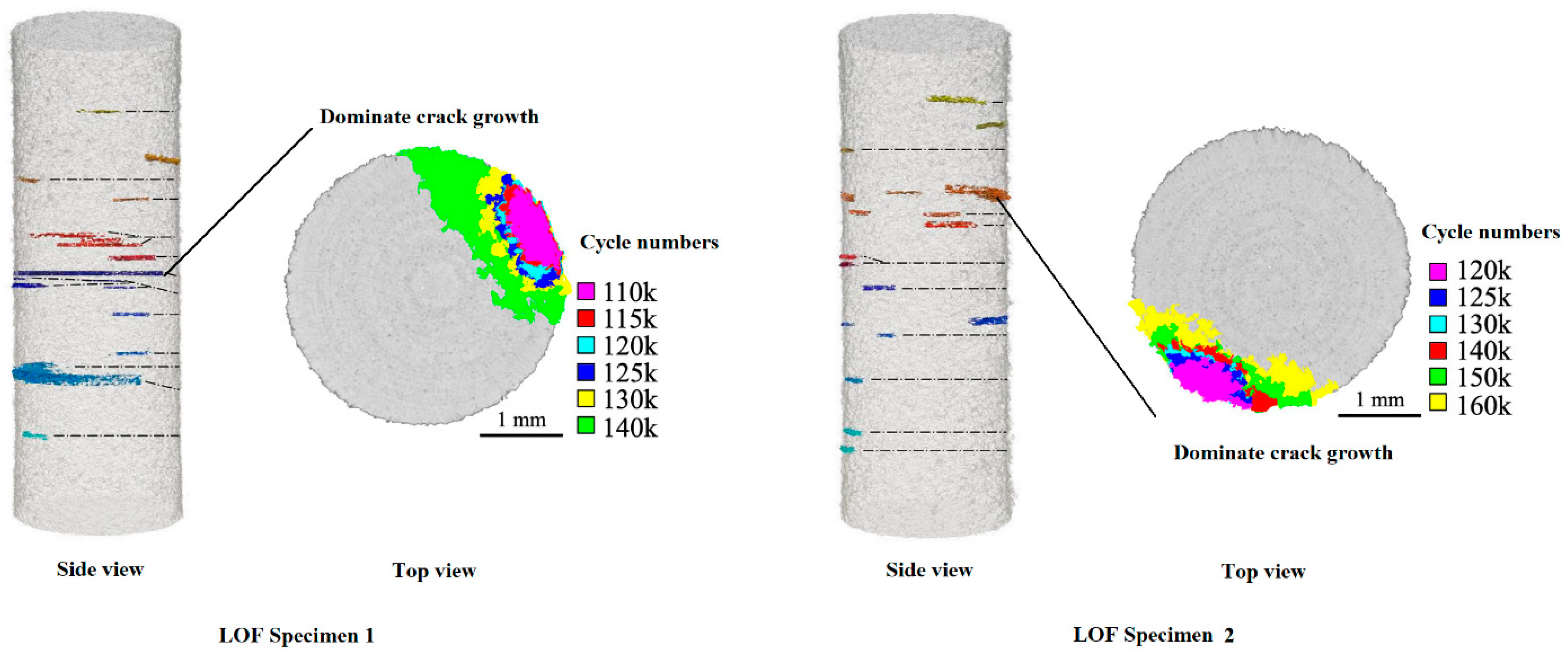
2.3. Crack Propagation

In addition to the MSC propagation life, N M S C , discussed in the previous subsection, the crack propagation process also encompasses plastic short crack (PSC) propagation life, N P S C , and long crack (LC) propagation life, N L C [84,88]. Different factors influence these stages of crack propagation: MSC, which accounts for a significant portion of the fatigue lifetime, is predominantly influenced by the microstructure [89]. In contrast, PSC propagation is largely governed by local plasticity, specifically elastic–plastic fracture mechanics, while LC propagation is determined by linear elastic fracture mechanics (LEFM).
To analyze crack propagation in L-PBF Ti-6Al-4V components, various methods have been employed to generate fatigue cracks, with each approach outlined in Table 4, including references and an assessment of their pros and cons. The first method, which is particularly suited to early stages of crack propagation, relies on natural processes where internal defects, residual stresses, and surrounding microstructures play significant roles. Its primary limitation is the unpredictability of the crack initiation location, which poses challenges in detection, monitoring, and analysis.
The second method involves the use of artificial defects, typically pre-designed via CAD and integrated during the AM process, allowing precise control over their size and location. However, these artificial defects tend to be larger than natural internal defects, and the microstructure and residual stresses around these defects are altered by the AM process, differing from those around natural defects.
For later stages of crack propagation, such as the LC stage, where the impact of surrounding microstructures is minimal, simpler methods such as introducing a manual notch or using a compact tension specimen are adequate. These approaches allow for precise control over the crack initiation site, originating from the manually introduced notch, facilitating straightforward monitoring and analysis.
Waddell et al. (2020) [45] proposed an in-situ approach to monitor small fatigue crack growth behavior in L-PBF as-built Ti-6Al-4V alloy, realized through a combination of in situ tomography and in situ energy dispersive X-ray diffraction (EDXRD). The synchrotron-based X-ray μCT, as shown in Figure 8a, enabled the crack evolution during cyclic loading (see in Figure 8b) and small crack interactions with the neighboring porosity to be captured.
X-ray μCT monitoring revealed that multiple cracks initiated and frequently engaged in crack bridging during the growth process, contributing to stress shielding [93,94] and leading to a subsequent reduction in the fatigue crack growth rate. This behavior aligns with the typical crack initiation from internal defects, which often involves the interaction and coalescence of multiple cracks at early stages. These eventually merge into a main crack that continues to propagate until the component fractures [95]. Additionally, crack growth deflections were commonly observed, particularly as the crack traversed from one building layer to another, influenced by the orientation of prior β grains.
During the crack growth process, interactions between cracks and porosity defects were noted to cause blunting at the crack tips, further impeding the crack growth rate. This mechanism of crack tip blunting and crack bridging leads to a slower growth rate for small cracks compared to long cracks (LC), contrary to what is typically expected. In some instances, interactions between cracks and defects increased the crack surface area and the crack front [96], affecting the propagation dynamics.
In conclusion, the impact of internal defects on crack propagation—whether beneficial or detrimental—largely depends on the size, shape, and orientation of the defects [97]. This underscores the need for further quantitative analyses to better understand these dynamics.
However, this assumption lacks robust empirical support. The initiation life of a crack is influenced not only by the a r e a but also by the morphology of the defect. For example, lack-of-fusion (LOF) defects are significantly more detrimental than gas pores of an equivalent a r e a [54], demonstrating that defect morphology plays a critical role in crack dynamics.
Cracks can form simultaneously within the same period, with secondary cracks eventually merging into the main crack at a later stage. Interestingly, the main crack was observed to initiate from the second largest defect, while the secondary crack originated from the largest defect. This was hypothesized to be due to the larger fine granular area surrounding the secondary defect [48]. However, this assumption lacks robust empirical support. The initiation life of a crack is influenced not only by the equivalent a r e a [55], demonstrating that defect morphology plays a critical role in crack dynamics.
During crack propagation, a plastic zone develops ahead of the crack front, which is approximately the same order of magnitude as the crack size. This is indicated by lattice strain measurements obtained through EDXRD [45], as shown in Figure 9. The lattice directly contributes to higher stress values at the crack tip. Its heterogeneity arises from variability in the microstructure, the presence of porosity, the tortuosity of the crack path, and the large gauge section used for diffraction measurements. Notably, considerable tensile and shear stresses were still observed in the vicinity of the advancing crack using unloaded EDXRD measurements. These stresses, indicative of residual stress from the L-PBF process, serve to accelerate crack growth behavior.
The location of an internal defect influences fatigue life, clearly impacting crack propagation. Hu et al. (2020) [39] investigated the impact of the distance from a defect to the surface of a sample. Their study identified a subsurface defect as one where the plastic zone intersects the free surface, although the defect itself may not be exposed at the surface. However, they did not specifically address the correlation between this distance and fatigue life. They introduced an effective defect area, denoted as a r e a e , for a two-dimensional irregularly shaped defect such as an LOF. This area was modified using a polygon that encompassed the defect, replacing the classical projected area for SIF calculations. They claimed that this effective area more realistically reflects the defect behavior because it also considers the plastic zone surrounding the defect.
For macroscale cracks, the FCGR is governed by the SIF of the crack front. The Murakami equation is the classical method for calculating the SIF of internal defect [69], which is
K I = Y · σ 0 · π · a r e a ,
where the geometry factor Y is 0.5 for internal defects and σ 0 is the maximum stress applied on the model. The Murakami equation is able to provide a relatively accurate estimation for internal defects, whereas it cannot consider the tropology, location, and orientation of an internal defect.
FEA provides a more accurate calculation of the stress intensity factor (SIF) for internal defects, taking into account geometry parameters and enabling the simulation of 3D crack propagation. Shao et al. (2023) [66] conducted a 3D LEFM FEA on fatigue crack propagation from internal-, subsurface-, and surface defects for L-BPF Ti-6Al-4V alloy. It predicted the crack evolution path and propagation life. The defect was modelled as a sphere where an elliptical crack front has been modelled as initiated from the spherical defect, as indicated in Figure 10a,b. The FEA enables the evaluation of the SIF (see in Figure 10c) and provides an estimation of the crack growth process from a gas pore, starting as an internal elliptical crack front, to break the free semi-elliptical surface crack, as indicated in Figure 10d. Influential parameters including defect size, shape and location were discussed, concluding that the size and depth were more influential to the fatigue cracking process, with respect to the highly stressed region when the defect is shallow to the free surface.
A recent study by Li et al. (2024) [55] advanced the field by building a complex 3D FE approach to simulate the crack propagation from an LOF. This approach innovated in realizing a modelling strategy to build an irregularly shaped crack front, which is consistent with a critical notch-like feature (see in Figure 11a) on an LOF. The whole notch profile has been replaced by an irregularly shaped crack front while maintained the same profile and dimensions (see in Figure 11b). The approach was able to predict all SIFs along the crack front, thus enabling the prediction of crack propagation from every corner along the crack front, initially from the notch to the fracture of a component, as shown in Figure 11. The research demonstrated that the classical SIF estimation method based on the projected area worked well for internal defects regardless of their shapes. However, it tends to be conservative for subsurface defects, as the crack has higher SIFs along the crack front when placing an LOF near to the free surface, as shown in Figure 11c. Therefore, introducing a surface defect distance factor is strongly suggested. The crack growth process was then predicted, as shown in Figure 10d, which shared a similar trend with the crack growth process from a gas pore (see in Figure 10d), while the crack front evolved more complexity due to the distribution of SIFs along the crack front.
Residual stresses significantly influence fatigue crack propagation, with their distribution being non-uniform due to the AM process strategies. This distribution is illustrated by contour plots from a compact tension specimen, as shown in Figure 12. Near the surface, the residual stresses are tensile, a characteristic attributed to the L-PBF process [98,99,100,101]. Internally, however, the residual stresses become compressive [102,103]. A comparison between the as-built specimen and the stress-relieved specimen showed that stress relief significantly reduced [44] but did not eliminate the residual stresses, similar to the effects observed with heat treatment [50]. As a result, an apparent increase in crack tip opening displacement (CTOD) was measured following stress relief, correlating directly with the changes in residual stress.
Residual stresses significantly influence the mechanics of crack propagation, particularly affecting near-threshold FCGR, crack closure effects, and the threshold SIF ΔKth. Compressive residual stresses can enhance crack closure, shifting near-threshold FCGR towards higher load ratios and reducing ΔKth by limiting the crack’s ability to open [50]. Despite the critical maximum SIF Kmax and intrinsic ΔKth being largely stress-state independent [104], the microstructure, specifically the columnar beta-grain structure, dictates crack propagation and orientation-dependent crack closure effects, altering the range of SIF ΔK and load ratio R depending on the residual stress distribution and sign [50,105]. This complexity highlights the intricate interplay between residual stress, material microstructure, and fatigue crack dynamics, underscoring the need for a comprehensive understanding of these factors in predicting and mitigating fatigue failure.

3. Microstructure

3.1. Microstructure in Different States

The microstructure of L-PBF Ti-6Al-4V alloy significantly differs from that of conventional wrought Ti-6Al-4V alloy and other AM methods due to its unique manufacturing process. Notably, the rapid cooling rates and high processing temperatures typically result in the formation of an α′ martensitic phase, as opposed to the α + β structure observed in wrought and E-PBF alloys. However, post-thermal treatments can considerably modify the microstructure, thereby profoundly influencing the fatigue properties of the material. This section examines the four most common microstructural states of L-PBF Ti-6Al-4V alloy: as-built, heat-treated, and HIPed. Subsequent discussion focuses on how these microstructural variations, particularly in conjunction with internal defects, affect the alloy’s fatigue properties.

3.1.1. As-Built Alloys

In an as-built state, the microstructures are generally a composition of acicular α′ martensite formed inside prior columnar β grains [106,107,108,109]. These prior β grains grow approximately epitaxially along the build direction and across multiple building layers, due to the directional thermal gradient and the partial re-melting of the previously deposed layers, as indicated in Figure 13a. Their sizes and shapes are generally irregular, around 120 ± 65 µm in width and 440 ± 250 µm in length when produced by optimal scanning energy (the optimal scanning energy aims for reducing the internal defects).
During manufacturing, α′ martensite forms within the β grains. Parallel α′-lath is the primary martensite, referred to as the Widmanstätten structure [21], as shown in Figure 13b. The α′ grains are much smaller than the β grains, with typical widths of around 1–2 µm, and uncorrelated from the energy density.
The energy density plays an important role in the size of prior β grains: a higher energy density statistically results in a larger melting pool; a lower thermal gradient thus leads to larger grain sizes. On the contrary, a lower energy density leads to finer microstructures [110]. The temperature gradient along the building direction also influences the length of the columnar grains, while their width is influenced by the hatching space [18].

3.1.2. After Post Heat Treatments

During the heat treatment process, the microstructure decomposed differently depending on the holding temperature and cooling rate [107,111,112]. Qu et al. (2023) [53] conducted an elaborate investigation into the influence of various heat treatments on the microstructure. When heated above 400 °C, the α′ martensite gradually decomposes into the α + β phase [113,114], although the α′ lath size does not change much until the temperature exceeds 750 °C. Stress relief, which is conducted at relatively low temperatures, does not significantly alter the phase composition of L-PBF Ti-6Al-4V alloy. The microstructure remains predominantly α′ martensitic. Stress relief allows for some recovery and recrystallization within the α′ martensite, resulting in slight coarsening of the microstructure and blurring of the α′ lath interfaces [53].
When the holding temperature is beyond 750 °C, the α phase interfaces become clear, and the α′ decomposes into fine α + β lamellae with discontinuous α phases at the prior grain boundaries. Concurrently, the α lamellae coarsen significantly but retain orientations like the original α′. At this stage, heat treatment does not significantly alter the morphology of prior β grains because the temperature remains below the β transus. As a result, only some prior β grain boundary fragments composed of the α phase can be distinguished, complicating the recognition of prior β grains. In contrast, the heat treatment causes α′ martensite to decompose, increasing the fraction of the β phase, as shown in Figure 14a. The acicular α′ martensite transforms into (α + β) lamellar structures, resulting in a bi-modal microstructure characterized by globularized and lamellar α structures interspersed with β phase inclusions, as illustrated in Figure 14b.
At 850 °C, massive α phases begin to aggregate within the prior β grains [22,115]. By 920 °C, a full basket-weave structure with interlaced α lamellae and coarse prior grain boundaries forms. When the holding temperature exceeds 1000 °C, the microstructure starts to lose its original characteristics, and the prior β grains grow significantly, transforming into a coarse Widmanstätten structure with newly formed acicular α laths [53].

3.1.3. After HIP

HIP is a manufacturing process used to enhance the properties of materials by applying high temperature and pressure uniformly in all directions. This technique eliminates porosity and increases the density of the material, resulting in improved mechanical properties and structural integrity. It typically operates at temperatures between 850 °C and 920 °C. This is similar to conventional heat treatment conditions, which are below the β transus. In general, due to the high-pressure argon atmosphere, the cooling rate of HIP is much slower than that of heat treatment, resulting in a more homogeneous microstructure with equiaxed α + β grains and coarser α-phase [116]. Alegre et al. (2022) [117] found that the microstructure obtained after HIP at 850 °C and 200 MPa for 2 h closely resembled that obtained from heat treatment at 850 °C followed by air cooling [109]. Due to the rapid cooling rate of HIP, the growth of the α phase thickness is very limited, increasing from 1.14 to 1.27 µm. This is thicker than the α phase after heat treatment, which measures around 1.8 µm [41].

3.2. Microstructure’s Role in High-Cycle Fatigue Performance

Microstructure plays a crucial role in the fatigue performance of L-PBF Ti-6Al-4V alloy, particularly in crack initiation and early-stage crack propagation, while its influence on macro fatigue crack propagation is less significant. Leyens and Peters (2006) [116] summarized the relationship between microstructural features and the fatigue properties of Ti-6Al-4V α + β alloy. They noted that a fine microstructure extends crack initiation life due to the increased number of grain boundaries, which act as barriers to dislocation movement [118]. Additionally, more uniformly distributed stresses reduce stress concentration.
The α′ martensitic phase, with its hexagonal close-packed (HCP) crystal structure, is hard and strong, providing high resistance to crack initiation. However, its inherent brittleness can lead to greater susceptibility to crack propagation. Conversely, the β phase, a body-centered cubic (BCC) structure stabilized by vanadium, enhances ductility and toughness, positively impacting fatigue properties. Both heat treatment and HIP processes increase the volume fraction of the β phase and alter residual stresses, thereby improving overall fatigue performance.
The microstructure has a coupling effect with the internal defects, which is vital for the fatigue performance of L-PBF Ti-6Al-4V alloy with internal defects. Through experimental investigation on the crack initiation and propagation from L-PBF Ti-6Al-4V alloy after different annealing processes, Qu et al. (2023) [53] observed some correlations between different types of microstructures and the fatigue cracking behavior: a hard martensite α′ microstructure (e.g., as-built, stress relief) is sensitive to internal defects with shape edges such as LOF, whereas a soft lamellar α + β microstructure (e.g., heat treatment at 920 °C) is more sensitive to pore-type defects such as entrapped gas pores or keyholes. Further increasing the heat treatment temperature beyond 1000 °C changed the microstructure into a coarse Widmanstätten structure with newly formed acicular α laths, which is completely different from the original microstructure. In this case, cracks tended to initiate from a single large colony of aligned α platelets with a cleavage-like appearance, and a few cracks initiate at “Widmanstätten” prior β grain boundaries, which is similar to fatigue cracking behavior of wrought titanium alloys. Some microstructural features promote certain fatigue mechanisms at the expense of the others [41]. Larger α colonies usually contribute to roughness-induced crack closure, thus increasing the ΔKth. However, they are less beneficial in reducing the growth of micro-cracks because they are less efficient to force the micro-cracks to change directions [119]. Moridi et al. (2019) [120] revealed that the primary α′ is particular prone to interface plasticity accommodating strain incompatibilities with the microstructure.

4. Post Processing Treatments

Post-processing techniques have considerable effects on the fatigue performance of L-PBF Ti-6Al-4V parts. These techniques work by altering residual stress, removing defects, or changing the microstructure, depending on the specific method used. This section provides an overview and discussion of the most representative post-processing methods for L-PBF Ti-6Al-4V alloy with internal defects and their impact on fatigue performance, specifically focusing on machining, heat treatment, and HIP. Other types of processing, such as shot peening, which is not directly associated with internal defects, are excluded.

4.1. Machining

Machining helps to prolong fatigue life by removing surface roughness, surface defects and subsurface cracks, which are common initiation points for fatigue cracks. Additionally, machining alters the distribution of residual stresses by removing surface material, thereby releasing surface residual stress. These residual stresses are often highest at the surface due to the rapid cooling and solidification during the AM process. Machining significantly reduces the magnitude of surface residual stresses while internal residual stresses remain compressive [52]. This redistribution of residual stress results in surface residual stresses becoming compressive, while internal residual stresses remain tensile but with a slightly decreased magnitude. Consequently, the fatigue life is affected, with performance changes under different stress amplitudes being generally insignificant [50], as indicated in Figure 14a.

4.2. Heat Treatment

Heat treatment typically involves holding the material at a temperature below the β-transus for a specified period, followed by furnace cooling to room temperature. This process can affect fatigue performance in three main ways: reducing residual stresses, refining the microstructure, and slightly impacting internal defects.
Heat treatment significantly reduces tensile residual stresses. Bhandari and Gaur (2023) [50] demonstrated that heat treatment reduced the maximum tensile residual stress of an as-built specimen from 432 MPa to 52 MPa. Similarly, Becker et al. (2020) [44] showed that stress relief heat treatment, which uses a lower holding temperature, could significantly reduce residual stresses, as illustrated in Figure 12. Due to the substantial reduction in residual stresses, the overall tensile stresses are dramatically lowered, resulting in improved fatigue life [52].
A commonly applied heat treatment involves holding the material at around 800–850 °C for 2 h in a vacuum or an inert atmosphere such as helium or argon, followed by furnace cooling to room temperature. This process optimizes the tensile properties, balancing strength and ductility, thereby enhancing fatigue resistance to crack initiation and propagation.
In addition to relaxing residual stresses and decomposing the microstructure, heat treatment slightly reduced the porosity fraction in as-built L-PBF Ti-6Al-4V alloy. Bhandari and Gaur (2023) [50] reported that heat treatment reduced the porosity fraction from 0.31% to 0.27% and decreased the maximum defect size from 468 µm to 437 µm. These reductions potentially lower the likelihood of crack initiation and extend the crack initiation life.

4.3. HIP

HIP is regarded as the most effective method for improving the fatigue performance of L-PBF Ti-6Al-4V alloy, as it simultaneously eliminates internal defects, reduces residual stress, and refines the microstructure. Similar to heat treatment, HIP uses a holding temperature between 800 °C and 995 °C, which is above the martensitic transformation start temperature but below the β-transus, and employs a similar holding time [116]. Additionally, a pressure of around 100–200 MPa is applied to the component.
The most significant benefit of HIP lies in its ability to eliminate most internal porosity in AM metal alloys [121]. The reduction in or elimination of porosity, along with the decomposition of the microstructure, contributes to an increased fatigue limit, extending both the crack initiation life and overall fatigue life. Additionally, fatigue cracks typically do not initiate from internal defects but from microstructural imperfections such as α phase laths and α + β interface decohesion, similar to wrought Ti-6Al-4V alloy, as shown in Figure 15.
However, HIP is not without its limitations. It is less effective at addressing subsurface and surface defects [122], and its impact on reducing surface residual stress is limited [51]. Furthermore, the process is very costly and may not be practical for large components [41].
When a crack initiates from the microstructure, such as in HIPed alloys, or from an internal defect after certain heat treatments, the calculation of the SIF does not solely depend on the projection area of the internal defect. In cases where the crack initiates from microstructural inhomogeneity (e.g., larger α-phase or clusters of α-phase) rather than internal AM defects [43,123], the SIF range K F G A can be calculated by
K F G A = Y · σ · π · a F G A
in which a F G A is the square root of the fine granular area including the defect area on the fracture surface, to replace the square root of the projected area of an internal defect.
Qu et al. (2023) [53] reported that small cracks within the circular bright area around entrapped gas pores grew by forming facets. This growth was controlled by the surrounding microstructures rather than ΔK at the crack tip. This behavior is similar to the formation of FGA in the VHCF regime [124] and HIP Ti-6Al-4V alloy.
Different post-processing approaches were combined to maximize their effects on improving the fatigue performance of L-PBF Ti-6Al-4V alloy by eliminating defects, reducing residual stresses, and decomposing the microstructure [50]. Hills et al. (2023) [125] reported that samples subjected to heat treatment and machining exhibited better fatigue performance than those treated with HIP and machining. Moreover, samples that underwent a combination of all three post-processing approaches demonstrated superior fatigue performance, even compared to wrought samples [50], as shown in Figure 16.

5. Machine Learning Models of Predicting Fatigue Life

Fully correlating the fatigue life performance with internal defects in L-PBF Ti-6Al-4V alloy, or AM metal alloys in general, is challenging due to the variety of dominating factors and influential parameters, as well as their coupling effects. ML is a promising method to achieve correlations by comprehensively considering all related parameters. ML is a branch of artificial intelligence that focuses on developing algorithms and statistical models that enable computers to learn from and make predictions or decisions based on data. Rather than being explicitly programmed to perform specific tasks, ML models identify patterns in data and improve their performance over time as they are exposed to more data.
Over the past few years, ML has raised considerable attentions to study the fatigue life of AM parts. Artificial neural networks (ANNs) have been the most widely used models, followed by random forest (RF), support vector machine (SVM), and other models [25]. Titanium alloy was the most studied AM metal alloy, constituting slightly over one third of the total literature on ML-based prediction of fatigue life.
Data-driven ML methods have been applied to predict the fatigue life of AM parts with inherent internal defects. An ANN is modelled after the neural networks in the human brain, where its fundamental processing unit is the artificial neuron. In ANN models, these neurons are frequently termed processing units. These neurons use input stimuli from samples and, through an iterative process of adjusting weight vectors, they minimize the difference between the network’s output and the expected result until a stable state is reached. The stimuli from the input samples are referred to as activation functions.
Li et al. (2022) [126] employed an ANN model to predict the VHCF life of L-PBF Ti-6Al-4V alloy; test data including defect size, defect location, defect depth, fatigue life, and building orientation were collected to train the ML model. The single-layer ANN is shown in Figure 17. Limited data for ML training represented a critical issue, where the study applied Monte Carlo simulation to enlarge the dataset size while preserving the interrelation between features. The random number generation technique was used to generate a large amount of fatigue data to avoid overfitting concern and ensured more effective training. The trained back-propagation ANN model was able to effectively seize the failure pattern of the dataset and distinguish one S–N curve caused by characteristic failure features from another.
Horňas et al. (2023) [127] also applied data-driven ML to predict the fatigue life of L-PBF Ti-6Al-4V alloy. Besides ANN, RP and SVM models have been used, and their performances were compared. The dataset was based on experimental data from µCT (defect size, locations, and shape) and fatigue tests (fatigue life and stress amplitude). Samples with different types of surface finish have been used for the ML dataset. The results showed the ANN model, which was similar to the one shown in Figure 16 [126] but employed three hidden layers, performed the best. For future development, more comprehensive ML models are suggested to achieve higher accuracy, by considering more fatigue-life-related factors including different types of AM, material, stress amplitude, stress ratio, residual stresses, and expanding the training set.
SVM, as a part of supervised learning, has emerged as a significant advancement in ML in recent years. The most commonly used SVM model for predicting fatigue life is the support vector regression (SVR), such as the model used by Horňas et al. (2023) [127] for the fatigue life of L-PBF Ti-6Al-4V alloy. It has been used to study the fatigue life of other types of AM metal alloys such as AlSi10Mg [128], 316L steel, and Inconel 718 [129]. RF models, as a statistical-learning-theory-based model, have high precision and good tolerance for outliners. They are also less prone to over-fitting. Zhan et al. [130,131,132] built RP models to predict fatigue life of different types of AM metal alloys, including Ti-6Al-4V [130], indicating that the performance of RP varied for different types of metal alloys. Other types of ML models or combined models have been used for L-PBF Ti-6Al-4V alloy, such as the deep-neural-network back-propagation model [133].
One critical disadvantage of data-driven ML methods is their heavy reliance on readily available and large amounts of data. These datasets were often obtained through fatigue tests that involved AM processing, pre- and post-processing, and advanced data acquisition methods (e.g., µCT, SEM). Obtaining such datasets is therefore time-consuming, costly, and requires researchers and engineers from different backgrounds to work closely.
One promising solution for overcoming the dataset limitation is to combine the ML models with established physics laws or phenomenological rules, known as physics-informed ML. Well-established methods such as LEFM and Paris’ law not only reduce the need for larger amount data but also enhance the accuracy of fatigue life prediction. Salvati et al. (2022) [134] proposed a hybrid method wherein the LEFM is incorporated with ML during the training process, as indicated in Figure 18. The Murakami method [69] for evaluating the SIF of defects in different locations and the empirical law [135] of the SIF range–fatigue life relation has been introduced as the physical constraint for the physical-informed neural networks (PINNs). The results showed that PINN improved predictions of around 83% compared with a pure NN-based ML tool and is suggested for problems where the dataset is insufficient. However, it should be noted that using the physical constraint is a gamble as the accuracy of the ML would not only depend on the dataset but also heavily rely on the reliability of the physical constraint.
In addition to linking inherent defects with fatigue performance, the ultimate goal is to establish a comprehensive correlation between AM processes and mechanical performance, with defective AM parts serving as the connecting bridge. Ciampaglia et al. (2023) [136] constructed a combined PINN algorithm composed of three subnetworks, namely the microstructural branch, defect branch, and output branch, as indicated in Figure 19. The blue dots represent the heat treatment variables, the manufacturing parameters are shown in red, and the fatigue life cycle is shown in yellow. The first two subnetworks worked independently to assess the effect of defect-associated (Φ) variables and the microstructural (θ) variables on the fatigue response. The results showed that the PINN model performed well on S–N curve results and was able to correlate the AM processing parameters and post-heat-treatment parameters with the fatigue performance. In addition, the PINN model, which was designed to enforce physical constraints, has certain advantages over the standard feed-forward neural network “black box” approach, including better understanding of the physics, reduced data requirements, and the ability to optimize AM parts design.

6. Conclusions and Perspective for Future Research

L-PBF for Ti-6Al-4V alloy is promising due to its superior adaptability over conventional manufacturing for producing complex geometries with high precision, customizing properties, and reducing material wastage. However, internal defects are a major reason for the insufficient HCF life performance of L-PBF Ti-6Al-4V alloy. Additionally, factors such as surrounding microstructure and residual stresses play significant roles. These internal defects and influencing factors vary with different processing parameters and post-processing treatments, often acting simultaneously and causing large variations in fatigue life performance. The insufficient understanding of these factors presents significant obstacles to the widespread adoption of L-PBF Ti-6Al-4V alloy. Therefore, it is essential to quantitatively correlate the individual and combined effects of these factors with fatigue life performance. Based on this exhaustive review, the key conclusions are summarized.
  • Research on different types of internal defects was extremely uneven, partially due to the occurrence frequency, detriment level, and difficulty of analysis for each defect type. As a result, gas porosity has been extensively and quantitatively investigated, recently followed by LOF defects. However, studies on other internal defect types, such as keyholes, balling, and α-phase facets, were rare. There is an urgent need for detailed research on these types of defects.
  • Quantitatively correlating LOFs with fatigue life performance is challenging due to their complex topology. Recent studies suggested that LOFs can be simplified based on their main profile and most critical embedded features, using an adapted SWT method to evaluate fatigue life. Comprehensive investigations are needed to further digitalize the geometric features of LOFs with a validated analytical approach. Additionally, the influence of un-melted powders embedded in LOFs needs to be investigated and clarified.
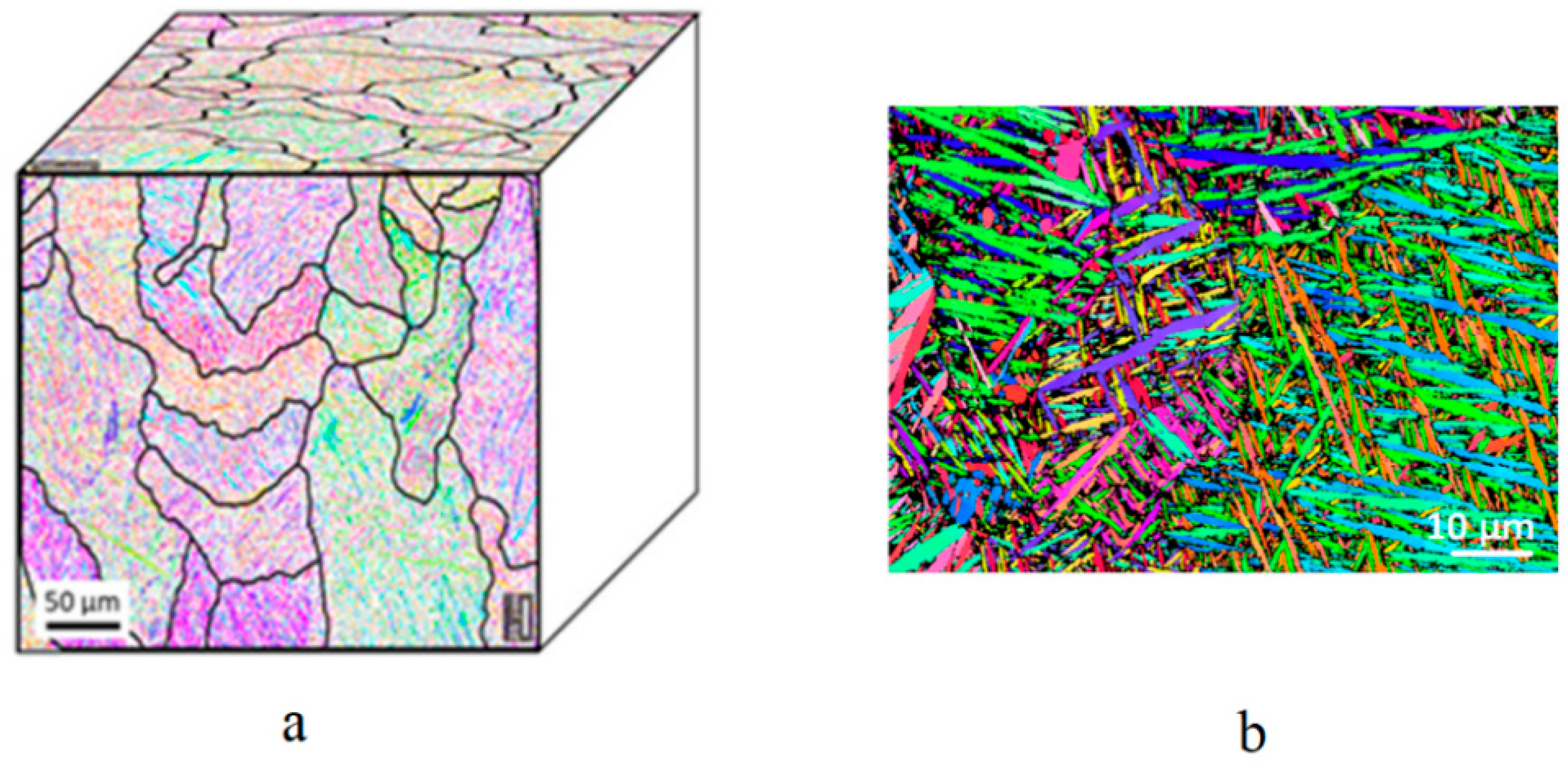
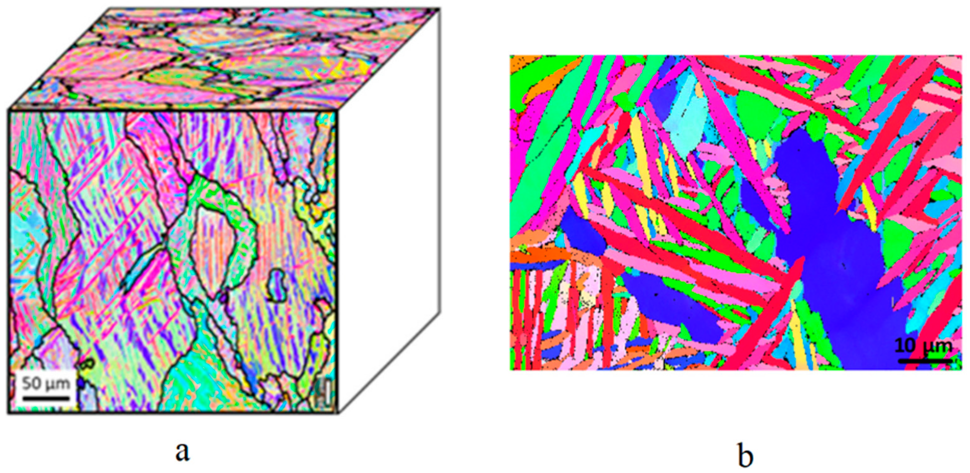
  • The microstructure composition of L-PBF Ti-6Al-4V alloy, especially in the as-built state, is distinct from conventionally manufactured Ti-6Al-4V alloy. Additionally, L-PBF Ti-6Al-4V alloy have more microstructural imperfections, such as dislocations, which introduce uncertainties in quantifying the microstructure’s role in early-stage crack evolution. To address this, the microstructures of L-PBF Ti-6Al-4V alloy under various conditions need to be standardized. Subsequently, the quantification of the microstructure’s role in fatigue life performance should be progressively investigated, starting with simple cases and advancing to more complex scenarios. This could begin with the fine α + β structure after heat treatment, progress to the α′ in the β phase of the as-built condition, and eventually include the coupling effects with internal defects.
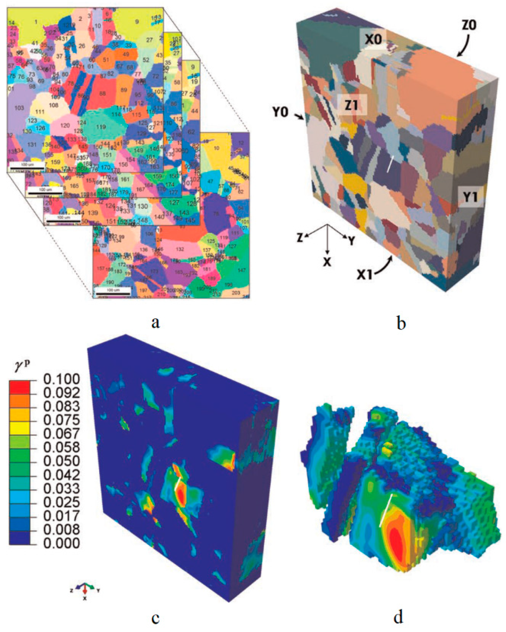
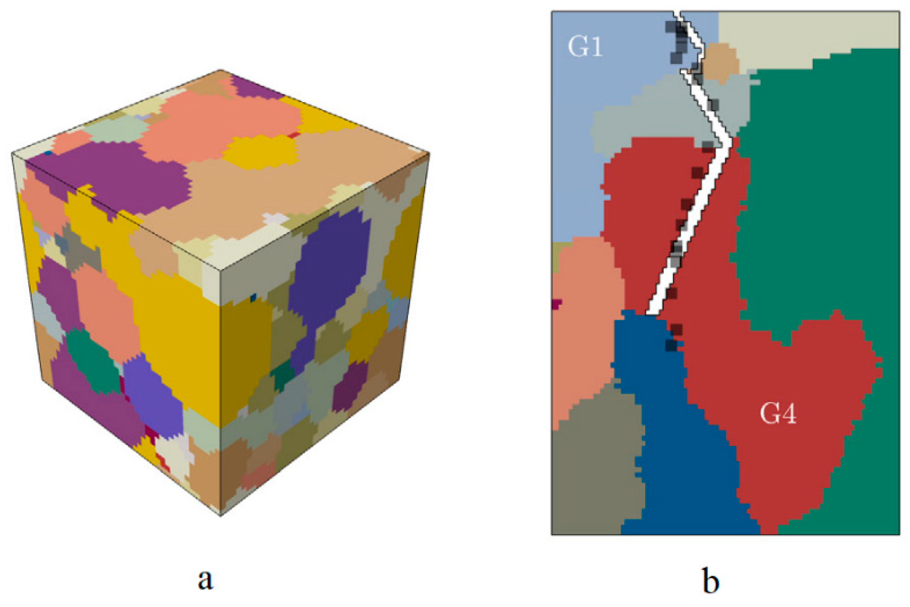
  • The surrounding microstructures around internal defects significantly influence fatigue crack initiation and MSC propagation. However, relevant research on AM Ti-6Al-4V alloy was very limited. While similar investigations on other types of metal alloys can be referenced, their findings cannot be directly applied due to distinct microstructures and properties. The CPFE approach may be an ideal solution to clarify the role of microstructures in fatigue life performance and reveal the mechanisms and behaviors of MSC propagation.
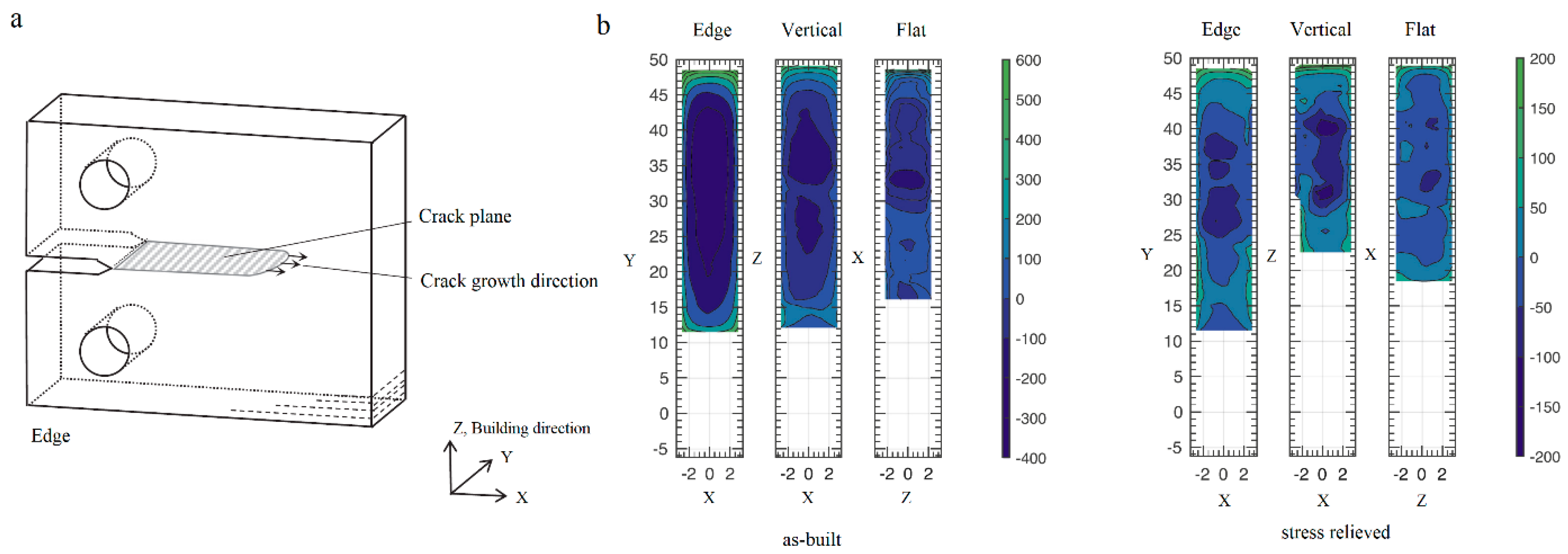
  • The distribution of residual stresses in L-PBF Ti-6Al-4V alloy, in both as-built and post-treated states (e.g., machining, heat treatments, and HIP), has been investigated and visualized in recent years. Understanding the mechanism by which fatigue life performance is altered is straightforward: residual stresses superpose the remote stresses. However, there is an urgent need to quantitatively correlate residual stresses in different states with fatigue crack evolution. Numerical analysis of residual stress formation during L-PBF processing and post-processing treatments, as well as its impact on fatigue crack evolution, can be both necessary and valuable.
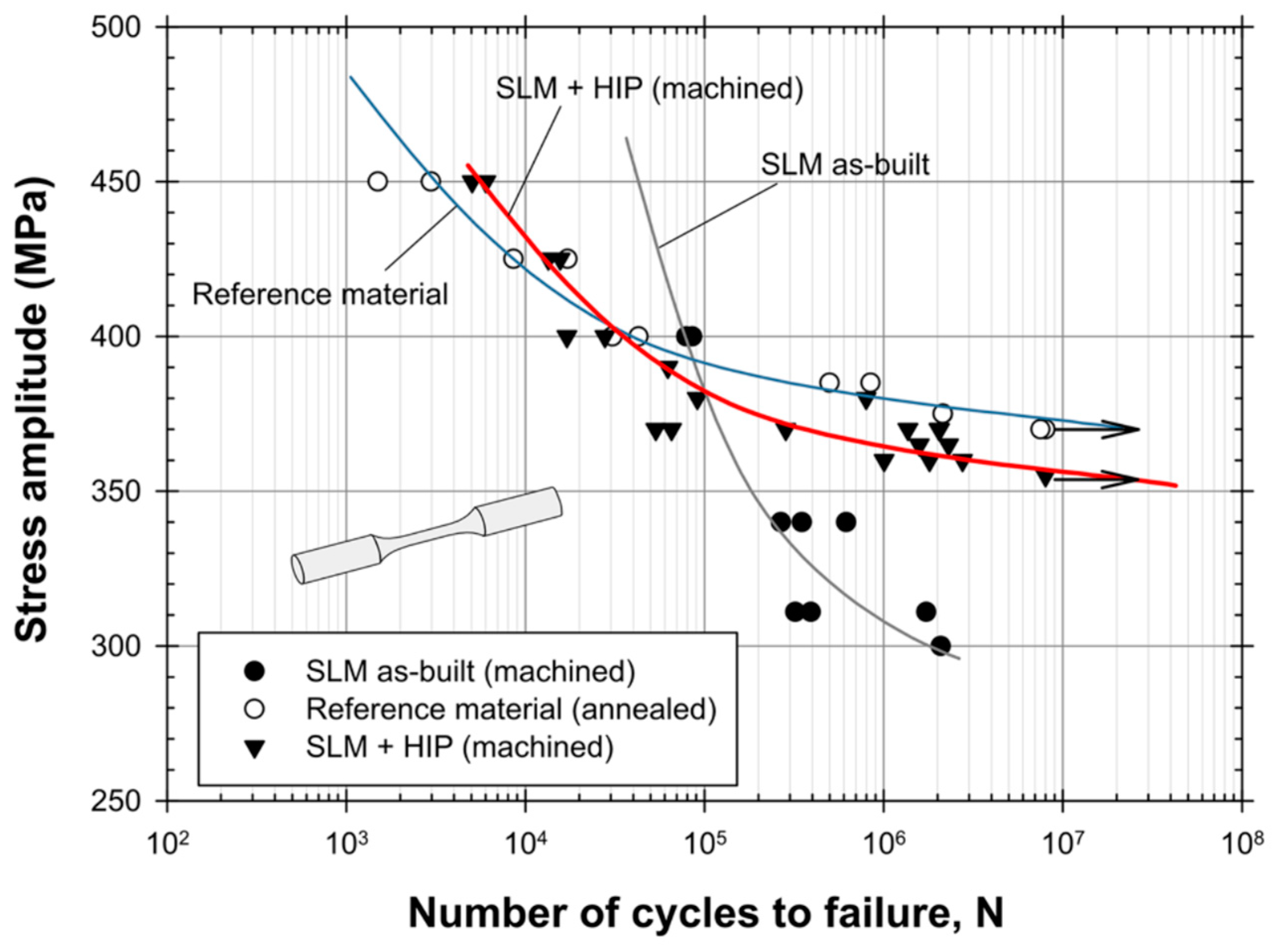
  • Post-processing techniques have a considerable impact on the fatigue life performance of L-PBF Ti-6Al-4V alloy. There have been in-depth investigations into various post-processing parameters (e.g., heat treatment at different temperatures, HIP) and studies combining different post-processing treatments (e.g., machining, heat treatment, and HIP), as suggested by previous review papers. Further research in this direction is needed to establish standardized post-processing treatments and combinations to achieve an optimal balance of mechanical properties for various application purposes.
  • Data-driven ML models seriously rely on the quantity and quality of dataset, and their contribution to the physical mechanism might be limited. Physics-informed ML models are more promising as they improve the prediction accuracy while requiring less data. In addition, they provide a deeper understanding of the physical mechanism than the pure data-driven models. FEA is an efficient solution for enlarging the dataset, on the premise of being validated.
Fully correlating the L-PBF process with fatigue properties of its manufactured Ti-6Al-4V component requires two components. The first component focuses on the correlation between the processing parameters and the component (e.g., mechanism of internal defect’s formation and microstructures’ evolution), whereas research focuses on the second component and tries to understand the role of such imperfections and microstructures’ role on the fatigue performance. Enormous studies are required from researchers with different backgrounds and interests to work on both components. Mutual exchanges and collaborations play a vital role in bridging knowledge efficiently from the two components. Full correlation is an extremely ambitious task, but only by its achievement could the L-PBF realize its complete advantages over conventional manufacturing techniques.

Author Contributions

Conceptualization, Z.L. and C.A.; methodology, Z.L.; formal analysis, Z.L.; investigation, Z.L.; resources, Z.L.; data curation, Z.L.; writing—original draft preparation, Z.L.; writing—review and editing, Z.L. and C.A.; project administration, Z.L. and C.A. All authors have read and agreed to the published version of the manuscript.

Funding

This research received no external funding.

Data Availability Statement

The raw data supporting the conclusions of this article will be made available by the authors on request.

Conflicts of Interest

The authors declare no conflicts of interest.

References

  1. Inagaki, I.; Takechi, T.; Shirai, Y.; Ariyasu, N. Application and features of titanium for the aerospace industry. Nippon Steel Sumitomo Met. Tech. Rep. 2014, 106, 22–27. [Google Scholar]
  2. Singh, P.; Pungotra, H.; Kalsi, N.S. On the characteristics of titanium alloys for the aircraft applications. Mater. Today Proc. 2017, 4, 8971–8982. [Google Scholar] [CrossRef]
  3. Uhlmann, E.; Kersting, R.; Klein, T.B.; Cruz, M.F.; Borille, A.V. Additive manufacturing of titanium alloy for aircraft components. Procedia Cirp 2015, 35, 55–60. [Google Scholar] [CrossRef]
  4. Emmelmann, C.; Scheinemann, P.; Munsch, M.; Seyda, V. Laser additive manufacturing of modified implant surfaces with osseointegrative characteristics. Phys. Procedia 2011, 12, 375–384. [Google Scholar] [CrossRef]
  5. Hao, Y.-L.; Li, S.-J.; Yang, R. Biomedical titanium alloys and their additive manufacturing. Rare Met. 2016, 35, 661–671. [Google Scholar] [CrossRef]
  6. Giannatsis, J.; Dedoussis, V. Additive fabrication technologies applied to medicine and health care: A review. Int. J. Adv. Manuf. Technol. 2009, 40, 116–127. [Google Scholar] [CrossRef]
  7. Bromberger, R.K.J. Additive Manufacturing: A Long-Term Game Changer for Manufacturers; McKinsey & Company: Chicago, IL, USA, 2017. [Google Scholar]
  8. Murr, L.E.; Gaytan, S.M.; Ramirez, D.A.; Martinez, E.; Hernandez, J.; Amato, K.N.; Shindo, P.W.; Medina, F.R.; Wicker, R.B.; Gaytan, S.M.; et al. Metal fabrication by additive manufacturing using laser and electron beam melting technologies. J. Mater. Sci. Technol. 2012, 28, 1–14. [Google Scholar] [CrossRef]
  9. Vayre, B.; Vignat, F.; Villeneuve, F. Designing for additive manufacturing. Procedia CIrP 2012, 3, 632–637. [Google Scholar] [CrossRef]
  10. Thijs, L.; Verhaeghe, F.; Craeghs, T.; Van Humbeeck, J.; Kruth, J.-P. A study of the microstructural evolution during selective laser melting of Ti–6Al–4V. Acta Mater. 2010, 58, 3303–3312. [Google Scholar] [CrossRef]
  11. Spierings, A.B.; Schneider, M.U.; Eggenberger, R. Comparison of density measurement techniques for additive manufactured metallic parts. Rapid Prototyp. J. 2011, 17, 380–386. [Google Scholar] [CrossRef]
  12. Gong, H.; Rafi, K.; Gu, H.; Ram, G.D.J.; Starr, T.; Stucker, B. Influence of defects on mechanical properties of Ti-6Al-4V components produced by selective laser melting and electron beam melting. Mater. Des. 2015, 86, 545–554. [Google Scholar] [CrossRef]
  13. Solberg, K.; Berto, F. What is going on with fatigue of additively manufactured metals? Mater. Des. Process. Commun. 2019, 1, e84. [Google Scholar] [CrossRef]
  14. Boyer, R.R. An overview on the use of titanium in the aerospace industry. Mater. Sci. Eng. A 1996, 213, 103–114. [Google Scholar] [CrossRef]
  15. Schijve, J. Fatigue of Structures and Materials; Springer: Dordrecht, The Netherlands, 2009; pp. 1–622. [Google Scholar]
  16. Morton, P.A.; Mireles, J.; Mendoza, H.; Cordero, P.M.; Benedict, M.; Wicker, R.B. Enhancement of Low-Cycle Fatigue Performance from Tailored Microstructures Enabled by Electron Beam Melting Additive Manufacturing Technology. J. Mech. Des. Trans. ASME 2015, 137, 114501. [Google Scholar] [CrossRef]
  17. Li, P.; Warner, D.H.; Fatemi, A.; Phan, N. Critical assessment of the fatigue performance of additively manufactured Ti-6Al-4V and perspective for future research. Int. J. Fatigue 2016, 85, 130–143. [Google Scholar] [CrossRef]
  18. Gao, X.; Tao, C.; Wu, S.; Chen, B.; Wu, S. X-ray imaging of defect population and the effect on high cycle fatigue life of laser additive manufactured Ti6Al4V alloys. Int. J. Fatigue 2022, 162, 106979. [Google Scholar] [CrossRef]
  19. Tammas-Williams, S.; Zhao, H.; Léonard, F.; Derguti, F.; Todd, I.; Prangnell, P.B. XCT analysis of the influence of melt strategies on defect population in Ti-6Al-4V components manufactured by Selective Electron Beam Melting. Mater. Charact. 2015, 102, 47–61. [Google Scholar] [CrossRef]
  20. Lewandowski, J.J.; Seifi, M. Metal additive manufacturing: A review of mechanical properties. Annu. Rev. Mater. Res. 2016, 46, 151–186. [Google Scholar] [CrossRef]
  21. Liu, S.; Shin, Y.C. Additive manufacturing of Ti6Al4V alloy: A review. Mater. Des. 2019, 164, 107552. [Google Scholar] [CrossRef]
  22. Pegues, J.W.; Shao, S.; Shamsaei, N.; Sanaei, N.; Fatemi, A.; Warner, D.H.; Li, P.; Phan, N. Fatigue of additive manufactured Ti-6Al-4V, Part I: The effects of powder feedstock, manufacturing, and post-process conditions on the resulting microstructure and defects. Int. J. Fatigue 2020, 132, 105358. [Google Scholar] [CrossRef]
  23. Molaei, R.; Fatemi, A.; Sanaei, N.; Pegues, J.; Shamsaei, N.; Shao, S.; Li, P.; Warner, D.H.; Phan, N. Fatigue of additive manufactured Ti-6Al-4V, Part II: The relationship between microstructure, material cyclic properties, and component performance. Int. J. Fatigue 2020, 132, 105363. [Google Scholar] [CrossRef]
  24. Sanaei, N.; Fatemi, A. Defects in additive manufactured metals and their effect on fatigue performance: A state-of-the-art review. Prog. Mater. Sci. 2021, 117, 100724. [Google Scholar] [CrossRef]
  25. Wang, H.; Gao, S.L.; Wang, B.T.; Ma, Y.T.; Guo, Z.J.; Zhang, K.; Yang, Y.; Yue, X.Z.; Hou, J.; Huang, H.J.; et al. Recent advances in machine learning-assisted fatigue life prediction of additive manufactured metallic materials: A review. J. Mater. Sci. Technol. 2024, 198, 111–136. [Google Scholar] [CrossRef]
  26. Singla, A.K.; Banerjee, M.; Sharma, A.; Singh, J.; Bansal, A.; Gupta, M.K.; Khanna, N.; Shahi, A.S.; Goyal, D.K. Selective laser melting of Ti6Al4V alloy: Process parameters, defects and post-treatments. J. Manuf. Process. 2021, 64, 161–187. [Google Scholar] [CrossRef]
  27. Cao, S.; Zou, Y.; Lim, C.V.S.; Wu, X. Review of laser powder bed fusion (LPBF) fabricated Ti-6Al-4V: Process, post-process treatment, microstructure, and property. Light Adv. Manuf. 2021, 2, 20. [Google Scholar] [CrossRef]
  28. Kan, W.H.; Chiu, L.N.S.; Lim, C.V.S.; Zhu, Y.; Tian, Y.; Jiang, D.; Huang, A. A critical review on the effects of process-induced porosity on the mechanical properties of alloys fabricated by laser powder bed fusion. J. Mater. Sci. 2022, 57, 9818–9865. [Google Scholar] [CrossRef]
  29. Jamhari, F.I.; Foudzi, F.M.; Buhairi, M.A.; Muhamad, N.; Mohamed, I.F.; Sulong, A.B.; Radzuan, N.A.M. Impact of hot isostatic pressing on surface quality, porosity and performance of Ti6Al4V manufactured by laser powder bed fusion: A brief review. J. Tribol. 2023, 36, 1–15. [Google Scholar]
  30. Nguyen, H.D.; Pramanik, A.; Basak, A.K.; Dong, Y.; Prakash, C.; Debnath, S.; Shankar, S.; Jawahir, I.S.; Dixit, S.; Buddhi, D. A critical review on additive manufacturing of Ti-6Al-4V alloy: Microstructure and mechanical properties. J. Mater. Res. Technol. 2022, 18, 4641–4661. [Google Scholar] [CrossRef]
  31. Jamhari, F.I.; Foudzi, F.M.; Buhairi, M.A.; Sulong, A.B.; Radzuan, N.A.M.; Muhamad, N.; Mohamed, I.F.; Jamadon, N.H.; Tan, K.S. Influence of heat treatment parameters on microstructure and mechanical performance of titanium alloy in LPBF: A brief review. J. Mater. Res. Technol. 2023, 24, 4091–4110. [Google Scholar] [CrossRef]
  32. Tusher, M.M.H.; Ince, A. High Cycle Fatigue and Very High Cycle Fatigue Performance of Selective Laser Melting Ti-6Al-4V Titanium Alloy—A Review. Mater. Perform. Charact. 2023, 12, 2. [Google Scholar] [CrossRef]
  33. Teixeira, Ó.; Silva, F.J.G.; Ferreira, L.P.; Atzeni, E. A review of heat treatments on improving the quality and residual stresses of the Ti–6Al–4V parts produced by additive manufacturing. Metals 2020, 10, 1006. [Google Scholar] [CrossRef]
  34. Singh, J.; Singh, H.; Singh, G. Effect of Post-Heat Treatment on the Properties of Additive Manufacturing Parts. In Innovative Processes and Materials in Additive Manufacturing; Elsevier: Amsterdam, The Netherlands, 2022; pp. 19–57. [Google Scholar]
  35. Wanhill, R.; Barter, S. Fatigue of Beta Processed and Beta Heat-Treated Titanium Alloys; Springer Science & Business Media: Berlin, Germany, 2011. [Google Scholar]
  36. Hagiwara, M.; Kitaura, T.; Ono, Y.; Yuri, T.; Ogata, T.; Kanou, O. High cycle fatigue properties of a minor boron-modified Ti–6Al–4V alloy. Mater. Trans. 2012, 53, 1486–1494. [Google Scholar] [CrossRef]
  37. Hagiwara, M.; Kaieda, Y.; Kawabe, Y.; Miura, S. Fatigue property enhancement of α-β titanium alloys by blended elemental P/M approach. ISIJ Int. 1991, 31, 922–930. [Google Scholar] [CrossRef]
  38. Du, L.; Qian, G.; Zheng, L.; Hong, Y. Influence of processing parameters of selective laser melting on high-cycle and very-high-cycle fatigue behaviour of Ti-6Al-4V. Fatigue Fract. Eng. Mater. Struct. 2021, 44, 240–256. [Google Scholar] [CrossRef]
  39. Hu, Y.N.; Wu, S.C.; Withers, P.J.; Zhang, J.; Bao, H.Y.X.; Fu, Y.N.; Kang, G.Z. The effect of manufacturing defects on the fatigue life of selective laser melted Ti-6Al-4V structures. Mater. Des. 2020, 192, 108708. [Google Scholar] [CrossRef]
  40. Akgun, E.; Zhang, X.; Lowe, T.; Zhang, Y.; Doré, M. Fatigue of laser powder-bed fusion additive manufactured Ti-6Al-4V in presence of process-induced porosity defects. Eng. Fract. Mech. 2022, 259, 108140. [Google Scholar] [CrossRef]
  41. Moquin, E.; Letenneur, M.; Kreitcberg, A.; Poulin-Masson, J.R.; Brailovski, V. High cycle fatigue resistance of laser powder bed fused Ti–6Al–4V alloys with processing-induced porosity: Towards damage-tolerant design of printed components. Mater. Sci. Eng. A 2023, 884, 145509. [Google Scholar] [CrossRef]
  42. Hu, Y.N.; Wu, S.C.; Wu, Z.K.; Zhong, X.L.; Ahmed, S.; Karabal, S.; Xiao, X.H.; Zhang, H.O.; Withers, P.J. A new approach to correlate the defect population with the fatigue life of selective laser melted Ti-6Al-4V alloy. Int. J. Fatigue 2020, 136, 105584. [Google Scholar] [CrossRef]
  43. Günther, J.; Krewerth, D.; Lippmann, T.; Leuders, S.; Tröster, T.; Weidner, A.; Biermann, H.; Niendorf, T. Fatigue life of additively manufactured Ti–6Al–4V in the very high cycle fatigue regime. Int. J. Fatigue 2017, 94, 236–245. [Google Scholar] [CrossRef]
  44. Becker, T.H.; Dhansay, N.M.; Haar, G.M.T.; Vanmeensel, K. Near-threshold fatigue crack growth rates of laser powder bed fusion produced Ti-Aal-4V. Acta Mater. 2020, 197, 269–282. [Google Scholar] [CrossRef]
  45. Waddell, M.; Walker, K.; Bandyopadhyay, R.; Kapoor, K.; Mallory, A.; Xiao, X.; Chuang, A.C.; Liu, Q.; Phan, N.; Sangid, M.D. Small fatigue crack growth behavior of Ti-6Al-4V produced via selective laser melting: In situ characterization of a 3D crack tip interactions with defects. Int. J. Fatigue 2020, 137, 105638. [Google Scholar] [CrossRef]
  46. Pessard, E.; Lavialle, M.; Laheurte, P.; Didier, P.; Brochu, M. High-cycle fatigue behavior of a laser powder bed fusion additive manufactured Ti-6Al-4V titanium: Effect of pores and tested volume size. Int. J. Fatigue 2021, 149, 106206. [Google Scholar] [CrossRef]
  47. Xu, Z.; Liu, A.; Wang, X.; Liu, B.; Guo, M. Fatigue limit prediction model and fatigue crack growth mechanism for selective laser melting Ti6Al4V samples with inherent defects. Int. J. Fatigue 2021, 143, 106008. [Google Scholar] [CrossRef]
  48. Chi, W.; Wang, W.; Li, Y.; Xu, W.; Sun, C. Defect induced cracking and modeling of fatigue strength for an additively manufactured Ti-6Al-4V alloy in very high cycle fatigue regime. Theor. Appl. Fract. Mech. 2022, 119, 103380. [Google Scholar] [CrossRef]
  49. Gao, X.; Tao, C.; Wu, S. Anisotropic high cycle fatigue property estimation for laser additive manufactured Ti6Al4V alloy dependence on tomographic imaging of defect population. J. Mater. Res. Technol. 2023, 22, 1971–1982. [Google Scholar] [CrossRef]
  50. Bhandari, L.; Gaur, V. Different post-processing methods to improve fatigue properties of additively built Ti-6Al-4V alloy. Int. J. Fatigue 2023, 176, 107850. [Google Scholar] [CrossRef]
  51. Mancisidor, A.M.; García-Blanco, M.B.; Quintana, I.; Arrazola, P.J.; Espinosa, E.; Cuesta, M.; Albizuri, J.; Garciandia, F. Effect of Post-Processing Treatment on Fatigue Performance of Ti6Al4V Alloy Manufactured by Laser Powder Bed Fusion. J. Manuf. Mater. Process. 2023, 7, 119. [Google Scholar] [CrossRef]
  52. Önder, S.; Saklakoğlu, N.; Sever, A. Selective laser melting of Ti6Al4V alloy: Effect of post-processing on fatigue life, residual stress, microstructure, microhardness and surface roughness. Mater. Charact. 2023, 196, 112571. [Google Scholar] [CrossRef]
  53. Qu, Z.; Zhang, Z.J.; Zhu, Y.K.; Liu, R.; Lu, S.L.; Li, S.J.; Duan, Q.Q.; Zhang, B.N.; Zhao, M.X.; Eckert, J.; et al. Coupling effects of microstructure and defects on the fatigue properties of laser powder bed fusion Ti-6Al-4V. Addit. Manuf. 2023, 61, 103355. [Google Scholar] [CrossRef]
  54. Meng, C.; Chen, J.; Hase, L.; Liu, Y. Image-based study on fatigue crack initiation mechanism of Ti-6Al-4V fabricated by laser-based powder bed fusion. Addit. Manuf. 2024, 86, 104216. [Google Scholar] [CrossRef]
  55. Li, Z.; Gut, A.; Burda, I.; Michel, S.; Gwerder, D.; Schuetz, P.; Romancuk, D.; Affolter, C. Investigation of individual lack-of-fusion defects in the fatigue performance of additive manufactured Ti6Al4V parts. 2024; under review. [Google Scholar]
  56. Biswal, R.; Syed, A.K.; Zhang, X. Assessment of the effect of isolated porosity defects on the fatigue performance of additive manufactured titanium alloy. Addit. Manuf. 2018, 23, 433–442. [Google Scholar] [CrossRef]
  57. Biswal, R.; Zhang, X.; Shamir, M.; Al Mamun, A.; Awd, M.; Walther, F.; Syed, A.K. Interrupted fatigue testing with periodic tomography to monitor porosity defects in wire + arc additive manufactured Ti-6Al-4V. Addit. Manuf. 2019, 28, 517–527. [Google Scholar] [CrossRef]
  58. Lauterbach, B.; Fieres, J.; Nigge, K.-M. Berücksichtigung von fertigungsbedingten Defekten in der strukturmechanischen Simulation. NAFEMS Mag. 2021, 1, 57. [Google Scholar]
  59. Siddique, S.; Imran, M.; Rauer, M.; Kaloudis, M.; Wycisk, E.; Emmelmann, C.; Walther, F. Computed tomography for characterization of fatigue performance of selective laser melted parts. Mater. Des. 2015, 83, 661–669. [Google Scholar] [CrossRef]
  60. Wan, H.; Wang, Q.; Jia, C.; Zhang, Z. Multi-scale damage mechanics method for fatigue life prediction of additive manufacture structures of Ti-6Al-4V. Mater. Sci. Eng. A. 2016, 669, 269–278. [Google Scholar] [CrossRef]
  61. Lukhi, M.; Kuna, M.; Hütter, G. Numerical investigation of low cycle fatigue mechanism in nodular cast iron. Int. J. Fatigue 2018, 113, 290–298. [Google Scholar] [CrossRef]
  62. Dinh, T.D.; Vanwalleghem, J.; Xiang, H.; Erdelyi, H.; Craeghs, T.; Paepegem, W.V. A unified approach to model the effect of porosity and high surface roughness on the fatigue properties of additively manufactured Ti6-Al4-V alloys. Addit. Manuf. 2020, 33, 101139. [Google Scholar] [CrossRef]
  63. Wang, Y.; Su, Z. Effect of micro-defects on fatigue lifetime of additive manufactured 316L stainless steel under multiaxial loading. Theor. Appl. Fract. Mech. 2021, 111, 102849. [Google Scholar] [CrossRef]
  64. Li, Z.; Gut, A.; Burda, I.; Michel, S.; Romancuk, D.; Affolter, C. The role of an individual lack-of-fusion defect in the fatigue performance of additive manufactured Ti-6Al-4V parts. In Proceedings of the I-AM 2022 International Additive Manufacturing Conference, Lisbon, Portugal, 19–20 October 2022. [Google Scholar]
  65. Xie, C.; Wu, S.; Yu, Y.; Zhang, H.; Hu, Y.; Zhang, M.; Wang, G. Defect-correlated fatigue resistance of additively manufactured Al-Mg4.5Mn alloy with in situ micro-rolling. J. Mater. Process. Technol. 2021, 291, 117039. [Google Scholar] [CrossRef]
  66. Shao, S.; Poudel, A.; Shamsaei, N. A linear elastic finite element approach to fatigue life estimation for defect laden materials. Eng. Fract. Mech. 2023, 285, 109298. [Google Scholar] [CrossRef]
  67. Murakami, Y.; Beretta, S. Small defects and inhomogeneities in fatigue strength: Experiments, models and statistical implications. Extremes 1999, 2, 123–147. [Google Scholar] [CrossRef]
  68. Sanaei, N.; Fatemi, A.; Phan, N. Defect characteristics and analysis of their variability in metal L-PBF additive manufacturing. Mater. Des. 2019, 182, 108091. [Google Scholar] [CrossRef]
  69. Yukitaka, M.; Masahiro, E. Quantitative evaluation of fatigue strength of metals containing various small defects or cracks. Eng. Fract. Mech. 1983, 17, 1–15. [Google Scholar] [CrossRef]
  70. Sterling, A.J.; Torries, B.; Shamsaei, N.; Thompson, S.M.; Seely, D.W. Fatigue behavior and failure mechanisms of direct laser deposited Ti-6Al-4V. Mater. Sci. Eng. A. 2016, 655, 100–112. [Google Scholar] [CrossRef]
  71. Vastola, G.; Pei, Q.X.; Zhang, Y.W. Predictive model for porosity in powder-bed fusion additive manufacturing at high beam energy regime. Addit. Manuf. 2018, 22, 817–822. [Google Scholar] [CrossRef]
  72. Wöhler, A. Versuche über die Festigkeit der Eisenbahnwagenachsen. Z. Für Bauwes. 1860, 10, 160–161. [Google Scholar]
  73. Basquin, O.H. The exponential law of endurance tests. Am. Soc. Test. Mater. Proc. 1910, 10, 625–630. [Google Scholar]
  74. Smith, K.; Topper, T.; Watson, P. A stress-strain function for the fatigue of metals. J. Mater. 1970, 5, 767–778. [Google Scholar]
  75. Anderson, T.L.; Anderson, T.L. Fracture Mechanics: Fundamentals and Applications; CRC Press: Boca Raton, FL, USA, 2005. [Google Scholar]
  76. Stephens, R.I.; Fatemi, A.; Stephens, R.R.; Fuchs, H.O. Metal Fatigue in Engineering; John Wiley & Sons: Hoboken, NJ, USA, 2000. [Google Scholar]
  77. Haile, J.M. Molecular Dynamics Simulation: Elementary Methods; John Wiley & Sons, Inc.: Hoboken, NJ, USA, 1992. [Google Scholar]
  78. Hirth, J.P.; Lothe, J.; Mura, T. Theory of dislocations. J. Appl. Mech. 1983, 50, 476–477. [Google Scholar] [CrossRef]
  79. Dieter, G.E.; Bacon, D. Mechanical Metallurgy; McGraw-hill: New York, NY, USA, 1976. [Google Scholar]
  80. Yang, X.; Ma, W.; Zhang, Z.; Liu, S.; Tang, H. Ultra-high specific strength Ti6Al4V alloy lattice material manufactured via selective laser melting. Mater. Sci. Eng. A 2022, 840, 142956. [Google Scholar] [CrossRef]
  81. Muiruri, A.; Maringa, M.; Preez, W.D. Evaluation of dislocation densities in various microstructures of additively manufactured Ti6Al4V (ELI) by the method of x-ray diffraction. Materials 2020, 13, 5355. [Google Scholar] [CrossRef] [PubMed]
  82. Shamir, M.; Syed, A.K.; Janik, V.; Biswal, R.; Zhang, X. The role of microstructure and local crystallographic orientation near porosity defects on the high cycle fatigue life of an additive manufactured Ti-6Al-4V. Mater. Charact. 2020, 169, 110576. [Google Scholar] [CrossRef]
  83. Signor, L.; Villechaise, P.; Ghidossi, T.; Lacoste, E.; Gueguen, M.; Courtin, S. Influence of local crystallographic configuration on microcrack initiation in fatigued 316LN stainless steel: Experiments and crystal plasticity finite elements simulations. Mater. Sci. Eng. A 2016, 649, 239–249. [Google Scholar] [CrossRef]
  84. Natkowski, E.; Durmaz, A.R.; Sonnweber-Ribic, P.; Münstermann, S. Fatigue lifetime prediction with a validated micromechanical short crack model for the ferritic steel EN 1.4003. Int. J. Fatigue 2021, 152, 106418. [Google Scholar] [CrossRef]
  85. Musinski, W.D.; McDowell, D.L. Simulating the effect of grain boundaries on microstructurally small fatigue crack growth from a focused ion beam notch through a three-dimensional array of grains. Acta Mater. 2016, 112, 20–39. [Google Scholar] [CrossRef]
  86. Farukh, F.; Zhao, L.; Jiang, R.; Reed, P.; Proprentner, D.; Shollock, B. Realistic microstructure-based modelling of cyclic deformation and crack growth using crystal plasticity. Comput. Mater. Sci. 2016, 111, 395–405. [Google Scholar] [CrossRef]
  87. Kuhn, J.; Schneider, M.; Sonnweber-Ribic, P.; Böhlke, T. Fast methods for computing centroidal Laguerre tessellations for prescribed volume fractions with applications to microstructure generation of polycrystalline materials. Comput. Methods Appl. Mech. Eng. 2020, 369, 113175. [Google Scholar] [CrossRef]
  88. McDowell, D.; Dunne, F. Microstructure-sensitive computational modeling of fatigue crack formation. Int. J. Fatigue 2010, 32, 1521–1542. [Google Scholar] [CrossRef]
  89. Castelluccio, G.M. A Study on the Influence of Microstructure on Small Fatigue Cracks. Ph.D. Thesis, Georgia Institute of Technology, Atlanta, GA, USA, 2012. [Google Scholar]
  90. Petrișor, S.M.; Savin, A.; Stanciu, M.D.; Prevorovsky, Z.; Soare, M.; Nový, F.; Steigmann, R. Complementary Methods for the Assessment of the Porosity of Laser Additive-Manufactured Titanium Alloy. Materials 2023, 16, 6383. [Google Scholar] [CrossRef]
  91. Ben, D.D.; Yang, H.J.; Ji, H.B.; Lian, D.L.; Meng, L.X.; Chen, J.; Yi, J.L.; Wang, L.; De Hosson, J.T.; Yang, R.; et al. Fatigue crack growth behavior in additive manufactured Ti6Al4V alloy with intentionally embedded spherical defect. Mater. Sci. Eng. A 2023, 885, 145612. [Google Scholar] [CrossRef]
  92. Ansari, M.A.; Crampton, A.; Garrard, R.; Cai, B.; Attallah, M. A Convolutional Neural Network (CNN) classification to identify the presence of pores in powder bed fusion images. Int. J. Adv. Manuf. Technol. 2022, 120, 5133–5150. [Google Scholar] [CrossRef]
  93. Walker, K.F.; Liu, Q.; Brandt, M. Evaluation of fatigue crack propagation behaviour in Ti-6Al-4V manufactured by selective laser melting. Int. J. Fatigue 2017, 104, 302–308. [Google Scholar] [CrossRef]
  94. Zhang, H.; Toda, H.; Qu, P.C.; Sakaguchi, Y.; Kobayashi, M.; Uesugi, K.; Suzuki, Y. Three-dimensional fatigue crack growth behavior in an aluminum alloy investigated with in situ high-resolution synchrotron X-ray microtomography. Acta Mater. 2009, 57, 3287–3300. [Google Scholar] [CrossRef]
  95. Qian, W.; Wu, S.; Wu, Z.; Ahmed, S.; Zhang, W.; Qian, G.; Withers, P.J. In situ X-ray imaging of fatigue crack growth from multiple defects in additively manufactured AlSi10Mg alloy. Int. J. Fatigue 2022, 155, 106616. [Google Scholar] [CrossRef]
  96. Tsay, L.; Shan, Y.-P.; Chao, Y.-H.; Shu, W. The influence of porosity on the fatigue crack growth behavior of Ti–6Al–4V laser welds. J. Mater. Sci. 2006, 41, 7498–7505. [Google Scholar] [CrossRef]
  97. Lee, J.; Hyun, S.; Kim, M.; Kim, M.; Ide, T.; Nakajima, H. Ductility improvement of intermetallic compound NiAl by unidirectional pores. Mater. Lett. 2012, 74, 213–216. [Google Scholar] [CrossRef]
  98. Mishurova, T.; Cabeza, S.; Artzt, K.; Haubrich, J.; Klaus, M.; Genzel, C.; Requena, G.; Bruno, G. An assessment of subsurface residual stress analysis in SLM Ti-6Al-4V. Materials 2017, 10, 348. [Google Scholar] [CrossRef]
  99. Xiao, Z.; Chen, C.; Zhu, H.; Hu, Z.; Nagarajan, B.; Guo, L.; Zeng, X. Study of residual stress in selective laser melting of Ti6Al4V. Mater. Des. 2020, 193, 108846. [Google Scholar] [CrossRef]
  100. Yakout, M.; Elbestawi, M.; Veldhuis, S.C. A study of the relationship between thermal expansion and residual stresses in selective laser melting of Ti-6Al-4V. J. Manuf. Process. 2020, 52, 181–192. [Google Scholar] [CrossRef]
  101. Xiao, Z.; Chen, C.; Hu, Z.; Zhu, H.; Zeng, X. Effect of rescanning cycles on the characteristics of selective laser melting of Ti6Al4V. Opt. Laser Technol. 2020, 122, 105890. [Google Scholar] [CrossRef]
  102. Wu, A.S.; Brown, D.W.; Kumar, M.; Gallegos, G.F.; King, W.E. An experimental investigation into additive manufacturing-induced residual stresses in 316L stainless steel. Metall. Mater. Trans. A 2014, 45, 6260–6270. [Google Scholar] [CrossRef]
  103. Li, C.; Liu, Z.; Fang, X.; Guo, Y. On the simulation scalability of predicting residual stress and distortion in selective laser melting. J. Manuf. Sci. Eng. 2018, 140, 041013. [Google Scholar] [CrossRef]
  104. Beghini, M.; Bertini, L. Fatigue crack propagation through residual stress fields with closure phenomena. Eng. Fract. Mech. 1990, 36, 379–387. [Google Scholar] [CrossRef]
  105. Vasudeven, A.; Sadananda, K.; Louat, N. A review of crack closure, fatigue crack threshold and related phenomena. Mater. Sci. Eng. A 1994, 188, 1–22. [Google Scholar] [CrossRef]
  106. Murr, L.; Quinones, S.A.; Gaytan, S.M.; Lopez, M.I.; Rodela, A.; Martinez, E.Y.; Hernandez, D.H.; Martinez, E.; Medina, F.; Wicker, R.B. Microstructure and mechanical behavior of Ti–6Al–4V produced by rapid-layer manufacturing, for biomedical applications. J. Mech. Behav. Biomed. Mater. 2009, 2, 20–32. [Google Scholar] [CrossRef]
  107. Vandenbroucke, B.; Kruth, J.P. Selective laser melting of biocompatible metals for rapid manufacturing of medical parts. Rapid Prototyp. J. 2007, 13, 196–203. [Google Scholar] [CrossRef]
  108. Vilaro, T.; Colin, C.; Bartout, J.-D. As-fabricated and heat-treated microstructures of the Ti-6Al-4V alloy processed by selective laser melting. Metall. Mater. Trans. A 2011, 42, 3190–3199. [Google Scholar] [CrossRef]
  109. Vrancken, B.; Thijs, L.; Kruth, J.-P.; Van Humbeeck, J. Heat treatment of Ti6Al4V produced by Selective Laser Melting: Microstructure and mechanical properties. J. Alloys Compd. 2012, 541, 177–185. [Google Scholar] [CrossRef]
  110. Han, J.; Yang, J.; Yu, H.; Yin, J.; Gao, M.; Wang, Z.; Zeng, X. Microstructure and mechanical property of selective laser melted Ti6Al4V dependence on laser energy density. Rapid Prototyp. J. 2017, 23, 217–226. [Google Scholar] [CrossRef]
  111. Li, H.; Jia, D.; Yang, Z.; Liao, X.; Jin, H.; Cai, D.; Zhou, Y. Effect of heat treatment on microstructure evolution and mechanical properties of selective laser melted Ti–6Al–4V and TiB/Ti–6Al–4V composite: A comparative study. Mater. Sci. Eng. A 2021, 801, 140415. [Google Scholar] [CrossRef]
  112. Yan, X.; Yin, S.; Chen, C.; Huang, C.; Bolot, R.; Lupoi, R.; Kuang, M.; Ma, W.; Coddet, C.; Liao, H.; et al. Effect of heat treatment on the phase transformation and mechanical properties of Ti6Al4V fabricated by selective laser melting. J. Alloys Compd. 2018, 764, 1056–1071. [Google Scholar] [CrossRef]
  113. Zhang, X.-Y.; Fang, G.; Leeflang, S.; Böttger, A.J.; Zadpoor, A.A.; Zhou, J. Effect of subtransus heat treatment on the microstructure and mechanical properties of additively manufactured Ti-6Al-4V alloy. J. Alloys Compd. 2018, 735, 1562–1575. [Google Scholar] [CrossRef]
  114. Wu, S.; Lu, Y.; Gan, Y.; Huang, T.; Zhao, C.; Lin, J.; Guo, S.; Lin, J. Microstructural evolution and microhardness of a selective-laser-melted Ti–6Al–4V alloy after post heat treatments. J. Alloys Compd. 2016, 672, 643–652. [Google Scholar] [CrossRef]
  115. Su, C.; Yu, H.; Wang, Z.; Yang, J.; Zeng, X. Controlling the tensile and fatigue properties of selective laser melted Ti–6Al–4V alloy by post treatment. J. Alloys Compd. 2021, 857, 157552. [Google Scholar] [CrossRef]
  116. Leyens, C.; Peters, M. Titanium and Titanium Alloys: Fundamentals and Applications; Wiley Online Library: Hoboken, NJ, USA, 2006. [Google Scholar]
  117. Alegre, J.M.; Díaz, A.; García, R.; Peral, L.B.; Cuesta, I.I. Effect of HIP post-processing at 850 °C/200 MPa in the fatigue behavior of Ti-6Al-4V alloy fabricated by Selective Laser Melting. Int. J. Fatigue 2022, 163, 107097. [Google Scholar] [CrossRef]
  118. Simonelli, M.; Tse, Y.Y.; Tuck, C. Effect of the build orientation on the mechanical properties and fracture modes of SLM Ti–6Al–4V. Mater. Sci. Eng. A 2014, 616, 1–11. [Google Scholar] [CrossRef]
  119. Lütjering, G.; Williams, J.C. Titanium Matrix Composites; Springer: Berlin/Heidelberg, Germany, 2007. [Google Scholar]
  120. Moridi, A.; Demir, A.G.; Caprio, L.; Hart, A.J.; Previtali, B.; Colosimo, B.M. Deformation and failure mechanisms of Ti–6Al–4V as built by selective laser melting. Mater. Sci. Eng. A 2019, 768, 138456. [Google Scholar] [CrossRef]
  121. Leuders, S.; Thöne, M.; Riemer, A.; Niendorf, T.; Tröster, T.; Richard, H.A.; Maier, H.J. On the mechanical behaviour of titanium alloy TiAl6V4 manufactured by selective laser melting: Fatigue resistance and crack growth performance. Int. J. Fatigue 2013, 48, 300–307. [Google Scholar] [CrossRef]
  122. Plessis, A.D.; Macdonald, E. Hot isostatic pressing in metal additive manufacturing: X-ray tomography reveals details of pore closure. Addit. Manuf. 2020, 34, 101191. [Google Scholar] [CrossRef]
  123. Sun, C.; Chi, W.; Wang, W.; Duan, Y. Characteristic and mechanism of crack initiation and early growth of an additively manufactured Ti-6Al-4V in very high cycle fatigue regime. Int. J. Mech. Sci. 2021, 205, 106591. [Google Scholar] [CrossRef]
  124. Zhang, L.-L.; Fei, Y.-H.; Liu, X.-Y.; Li, M.-X. On the formation mechanisms of fine granular area (FGA) on the fracture surface for high strength steels in the VHCF regime. Int. J. Fatigue 2016, 82, 402–410. [Google Scholar]
  125. Hills, M.A.; Malcolm, J.S.; Dhansay, N.M.; Becker, T.H. High cycle fatigue strength of hot isostatically pressed and chemically etched laser powder bed fusion produced Ti-6Al-4V. Int. J. Fatigue 2023, 175, 107774. [Google Scholar] [CrossRef]
  126. Li, J.; Yang, Z.; Qian, G.; Berto, F. Machine learning based very-high-cycle fatigue life prediction of Ti-6Al-4V alloy fabricated by selective laser melting. Int. J. Fatigue 2022, 158, 106764. [Google Scholar] [CrossRef]
  127. Horňas, J.; Běhal, J.; Homola, P.; Senck, S.; Holzleitner, M.; Godja, N.; Pásztor, Z.; Hegedüs, B.; Doubrava, R.; Růžek, R.; et al. Modelling fatigue life prediction of additively manufactured Ti-6Al-4V samples using machine learning approach. Int. J. Fatigue 2023, 169, 107483. [Google Scholar] [CrossRef]
  128. Wang, H.; Li, B.; Xuan, F.-Z. Fatigue-life prediction of additively manufactured metals by continuous damage mechanics (CDM)-informed machine learning with sensitive features. Int. J. Fatigue 2022, 164, 107147. [Google Scholar] [CrossRef]
  129. Luo, Y.; Zhang, B.; Feng, X.; Song, Z.M.; Qi, X.B.; Li, C.P.; Chen, G.F.; Zhang, G.P. Pore-affected fatigue life scattering and prediction of additively manufactured Inconel 718: An investigation based on miniature specimen testing and machine learning approach. Mater. Sci. Eng. A 2021, 802, 140693. [Google Scholar] [CrossRef]
  130. Zhan, Z.; Hu, W.; Meng, Q. Data-driven fatigue life prediction in additive manufactured titanium alloy: A damage mechanics based machine learning framework. Eng. Fract. Mech. 2021, 252, 107850. [Google Scholar] [CrossRef]
  131. Zhan, Z.; Li, H. Machine learning based fatigue life prediction with effects of additive manufacturing process parameters for printed SS 316L. Int. J. Fatigue 2021, 142, 105941. [Google Scholar] [CrossRef]
  132. Zhan, Z.; Li, H. A novel approach based on the elastoplastic fatigue damage and machine learning models for life prediction of aerospace alloy parts fabricated by additive manufacturing. Int. J. Fatigue 2021, 145, 106089. [Google Scholar] [CrossRef]
  133. Jia, Y.; Fu, R.; Ling, C.; Shen, Z.; Zheng, L.; Zhong, Z.; Hong, Y. Fatigue life prediction based on a deep learning method for Ti-6Al-4V fabricated by laser powder bed fusion up to very-high-cycle fatigue regime. Int. J. Fatigue 2023, 172, 107645. [Google Scholar] [CrossRef]
  134. Salvati, E.; Tognan, A.; Laurenti, L.; Pelegatti, M.; De Bona, F. A defect-based physics-informed machine learning framework for fatigue finite life prediction in additive manufacturing. Mater. Des. 2022, 222, 111089. [Google Scholar] [CrossRef]
  135. Murakami, Y.; Endo, M. Effects of hardness and crack geometries on delta k sub th of small cracks emanating from small defects. In The Behaviour of Short Fatigue Cracks; Mechanical Engineering Publications: London, UK, 1986; pp. 275–293. [Google Scholar]
  136. Ciampaglia, A.; Tridello, A.; Paolino, D.; Berto, F. Data driven method for predicting the effect of process parameters on the fatigue response of additive manufactured AlSi10Mg parts. Int. J. Fatigue 2023, 170, 107500. [Google Scholar] [CrossRef]
Figure 1. Two major internal defects on the fracture surface L-PBF Ti-6Al-4V alloy observed using scanning electron microscopy.
Metals 14 00972 g001
Figure 2. S–N data of 10 groups of L-PBF Ti-6Al-4V samples with different porosities. Reprinted from ref. [38].
Metals 14 00972 g002
Figure 3. Multiple cracks initiating and propagating in one L-PBF Ti-6Al-4V specimens, monitored by periodical µCT. Reprinted with permission from ref. [54]. 2024. Elsevier.
Metals 14 00972 g003
Figure 4. (a) X-ray CT image of Specimen FT-1, (b) FE mesh of a reduced section of specimen gauge section taken from X-ray CT, (c) schematic of a sub-surface pore modelled with idealized geometries and symmetry boundary condition, (d) FE mesh of the idealized sub-surface pore. Reprinted with from ref. [57].
Metals 14 00972 g004
Figure 5. Three-dimensional reconstruction and mesh of the polycrystalline aggregate containing the studied crack: (a) illustration of the stack of the 29 EBSD 2D maps, (b) 3D reconstructed aggregate, (c) cumulated plastic slip on the slip system after the two simulated cycles of the aggregate and (d) the grain surrounding the crack. Reprinted with permission from ref. [83]. 2016. Elsevier.
Metals 14 00972 g005
Figure 6. (a) SVE tessellations [87]; (b) simulated crack path and mapped crack from SEM (black points). G1 and G4 refer to different grains. Reprinted with permission from ref. [84]. 2021. Elsevier.
Metals 14 00972 g006
Figure 7. (a) Artificial microstructure and mesh; (b) stress contour at 1% strain; (c) short crack growth path in pseudo-3D model predicted from XFEM (crack growth length 163.8 µm). In (c), A and B refer to different grains. Reprinted from ref. [86].
Metals 14 00972 g007
Figure 8. X-ray μCT views of the crack front and porosity: (a) sample and notch, and overview of the map; (b) top view of the crack front profile during evolving number of cycles. Reprinted with permission from ref. [45]. 2020. Elsevier.
Metals 14 00972 g008
Figure 9. EDXRD measured elastic strain: (a) normal strain, (b) shear strain, and (c) projected reconstruction (the ‘2’ refers to the tensile direction in the coordinate system). Reprinted with permission from ref. [45]. 2020. Elsevier.
Metals 14 00972 g009
Figure 10. FEA of crack growth from a subsurface pore: (a) 3D model and parameters; (b) FE model; (c) normalized SIF with respect to the crack length when h/r = 1; (d) crack growth process. Reprinted with permission from ref. [66]. 2023. Elsevier.
Metals 14 00972 g010
Figure 11. FEA of crack growth from a subsurface LOF: (a) notch from an LOF, which is replaced by (b) an irregularly shaped crack front; (c) SIFs along the crack front from A to I indicated in (a); and (d) the crack growth process from a subsurface LOF. “A” to “I” are the locations along the cracj front. Reprinted from ref. [55].
Metals 14 00972 g011
Figure 12. (a) Compact tension specimen; (b) contour plots of residual stress values of the as-built and stress-relieved samples. Reprinted with permission from ref. [44]. 2020. Elsevier.
Metals 14 00972 g012
Figure 13. Typical microstructures for as-built L-PBF Ti-6Al-4V alloy: (a) prior columnar β grains; (b) α′ lath in the plane perpendicular to the building direction. Reprinted with permission from ref. [41]. 2023. Elsevier.
Metals 14 00972 g013
Figure 14. Typical microstructures for heat-treated L-PBF Ti-6Al-4V alloy: (a) β grains; (b) α′ lath in the plane perpendicular to the building direction. Reprinted with permission from ref. [41]. 2023. Elsevier.
Metals 14 00972 g014
Figure 15. Fatigue test results for the three studied conditions: as-built SLM, SLM + HIP, reference wrought material. Reprinted from ref. [115].
Metals 14 00972 g015
Figure 16. S–N curve for L-PBF Ti-6Al-4V samples with combinations of different post-processing approaches. Note that “HT” stands for heat treatment, “AB” stands for as-built, and “M” stands for machining. Reprinted with permission from ref. [50]. 2023. Elsevier.
Metals 14 00972 g016
Figure 17. ANN with single layers. Reprinted with permission from ref. [126]. 2022. Elsevier.
Metals 14 00972 g017
Figure 18. A combined ML and LEFM approach for fatigue life prediction. Reprinted from [134].
Metals 14 00972 g018
Figure 19. The neural network architecture of the PINN, which is composed of three subnetworks. In red are the manufacturing parameters, in green are heat treatment variables and in yellow is the life cycle. Dashed lines indicate custom layers, while continuous lines indicate neural network connections. Reprinted with permission from ref. [136]. 2023. Elsevier.
Metals 14 00972 g019
Table 4. A summary of different methods to initiate fatigue cracks in L-PBF Ti-6Al-4V parts, with their pros and cons.
No.MethodProsConsReferences
1Natural internal defectsConform to realityDifficult to control the initiation site[45,90]
2Artificial defect by computer aid design (CAD)Size, morphology, and location are controlled, regarded as an internal defect(1) Defects are usually much larger than natural defects; (2) residual stress is not natural; (3) unfused powders inside[91,92]
3Manual notchCrack initiation site is controlled(1) Not desirable for crack propagation at early stages; (2) cracks do not initiate from internal defects[45]
4CT specimenStandardized crack propagation approachOnly to study crack propagation [44]
Disclaimer/Publisher’s Note: The statements, opinions and data contained in all publications are solely those of the individual author(s) and contributor(s) and not of MDPI and/or the editor(s). MDPI and/or the editor(s) disclaim responsibility for any injury to people or property resulting from any ideas, methods, instructions or products referred to in the content.

