
Study on the Surface Quality of Overhanging Holes Fabricated by Additive/Subtractive Hybrid Manufacturing for Ti6Al4V Alloy
Abstract
:1. Introduction
2. Method and Experimental Procedure
2.1. Mechanism of Sinkage Generation
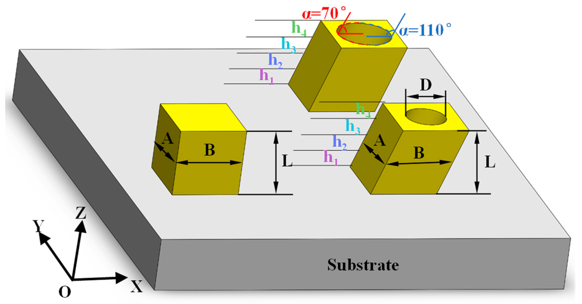
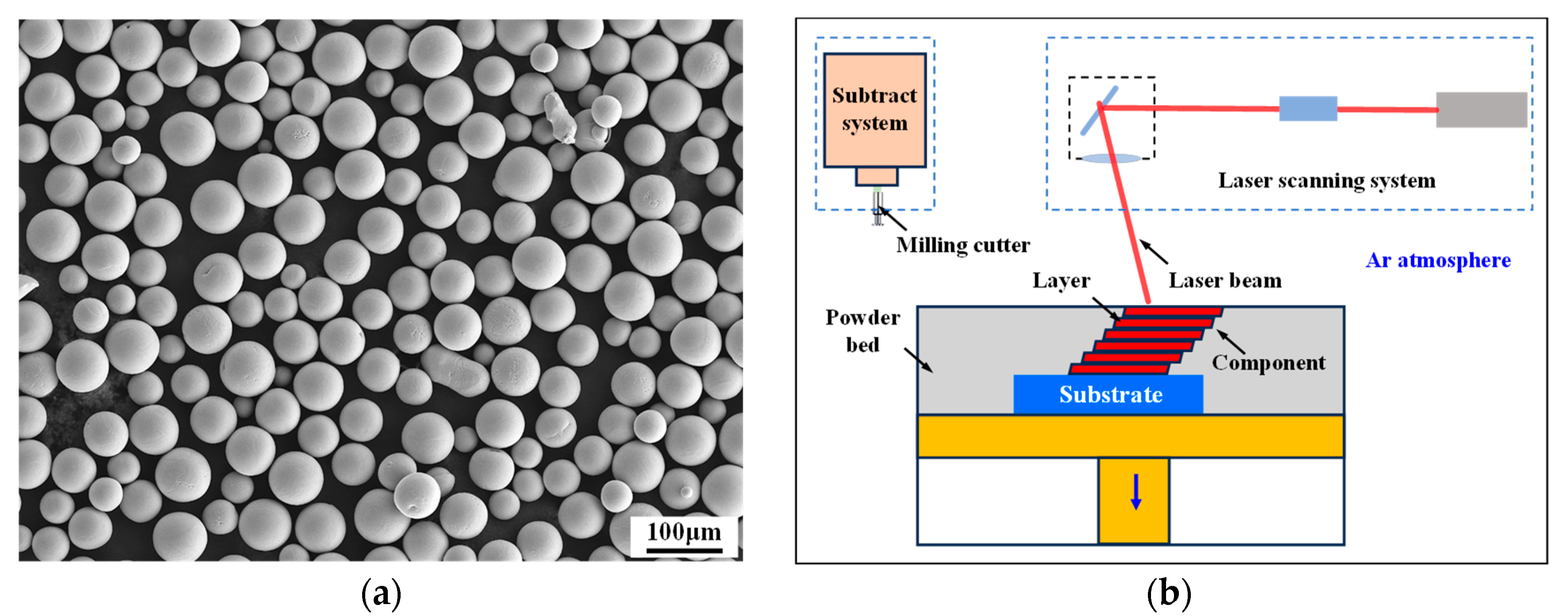
2.2. Experimental Procedure
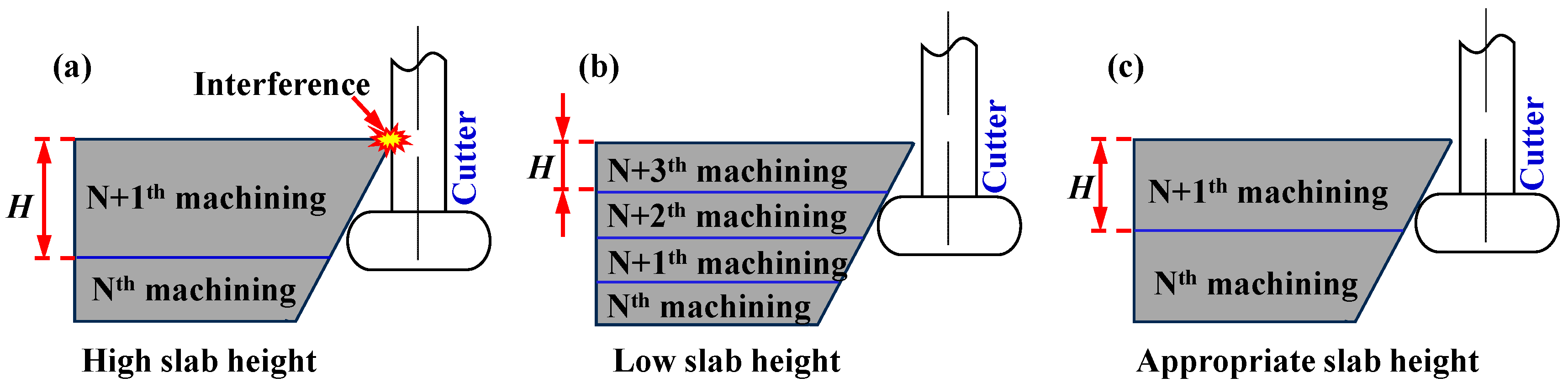
2.3. Determination of Slab Height H
2.4. Characterization Methods
3. Results and Discussion
3.1. Microstructure Bonding at the Alternating Interfaces of ASHM
3.2. Surface Quality of Overhanging Holes for ASHM
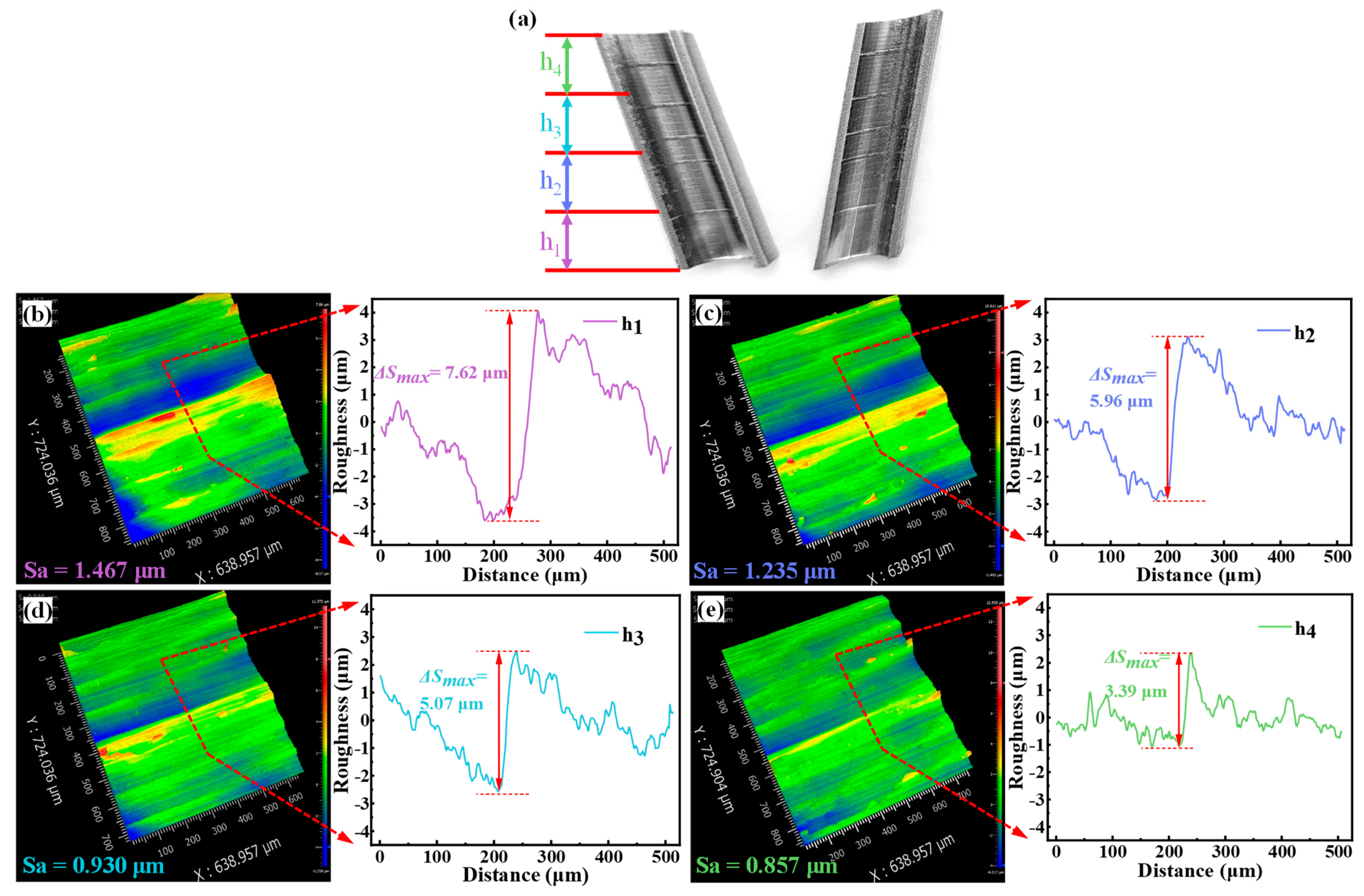
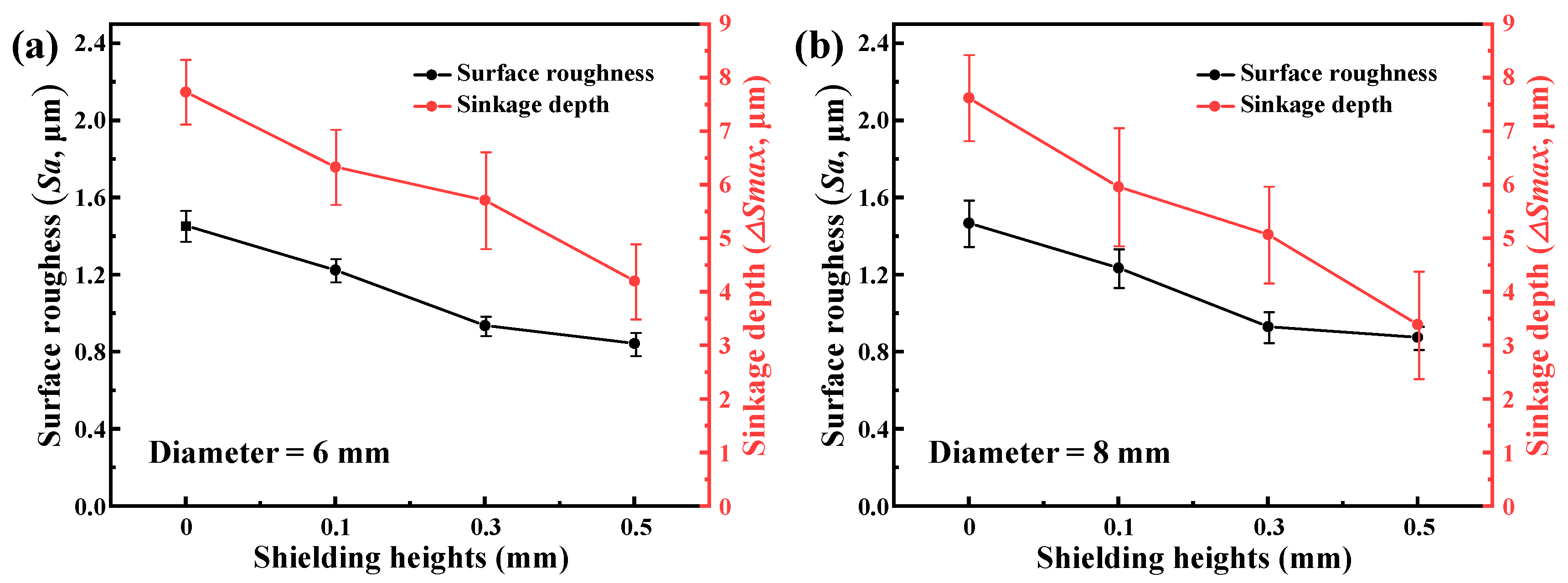
3.2.1. Surface Quality at Different Shielding Heights
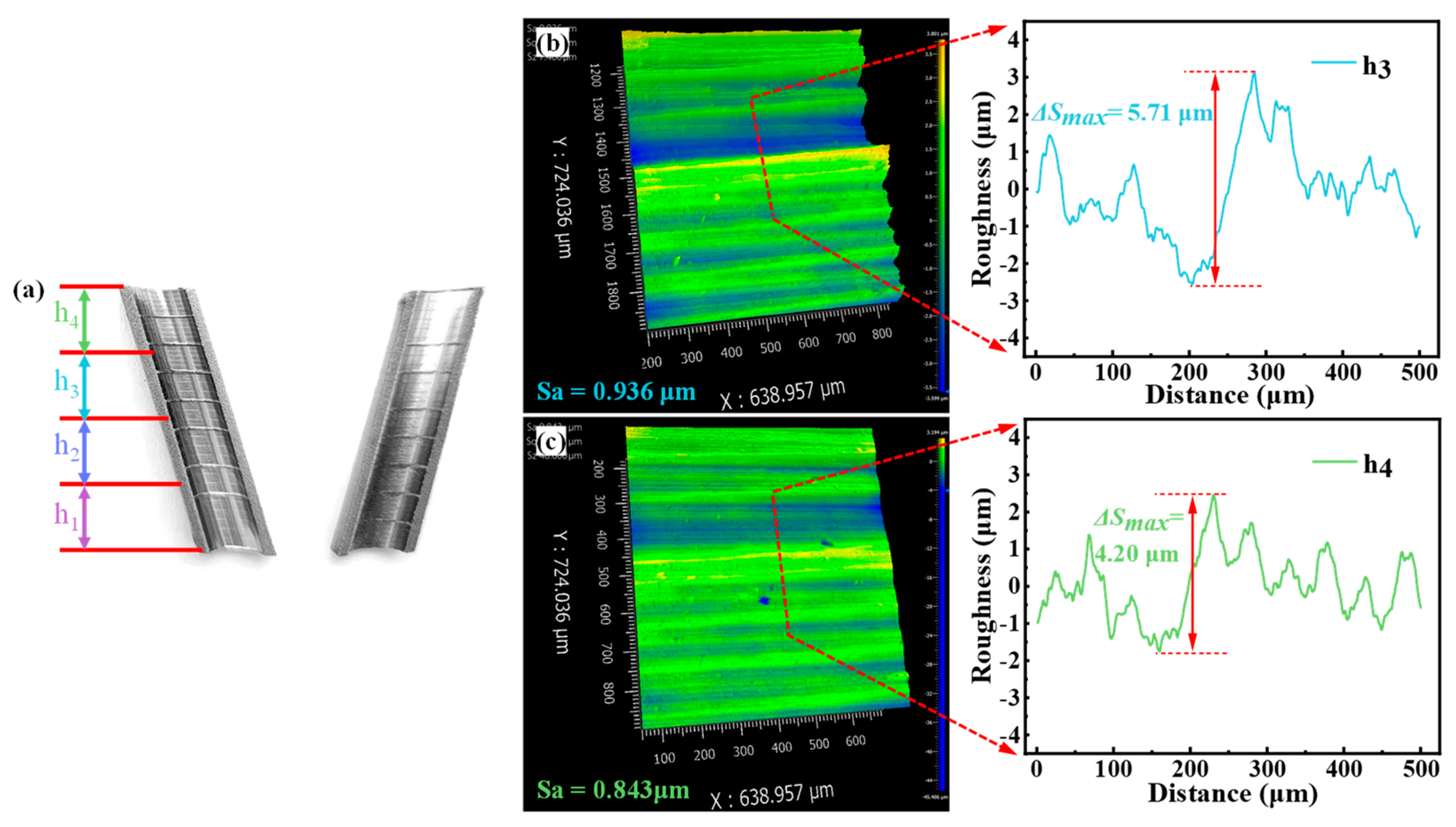
3.2.2. Surface Quality of Overhanging Holes with Different Diameters
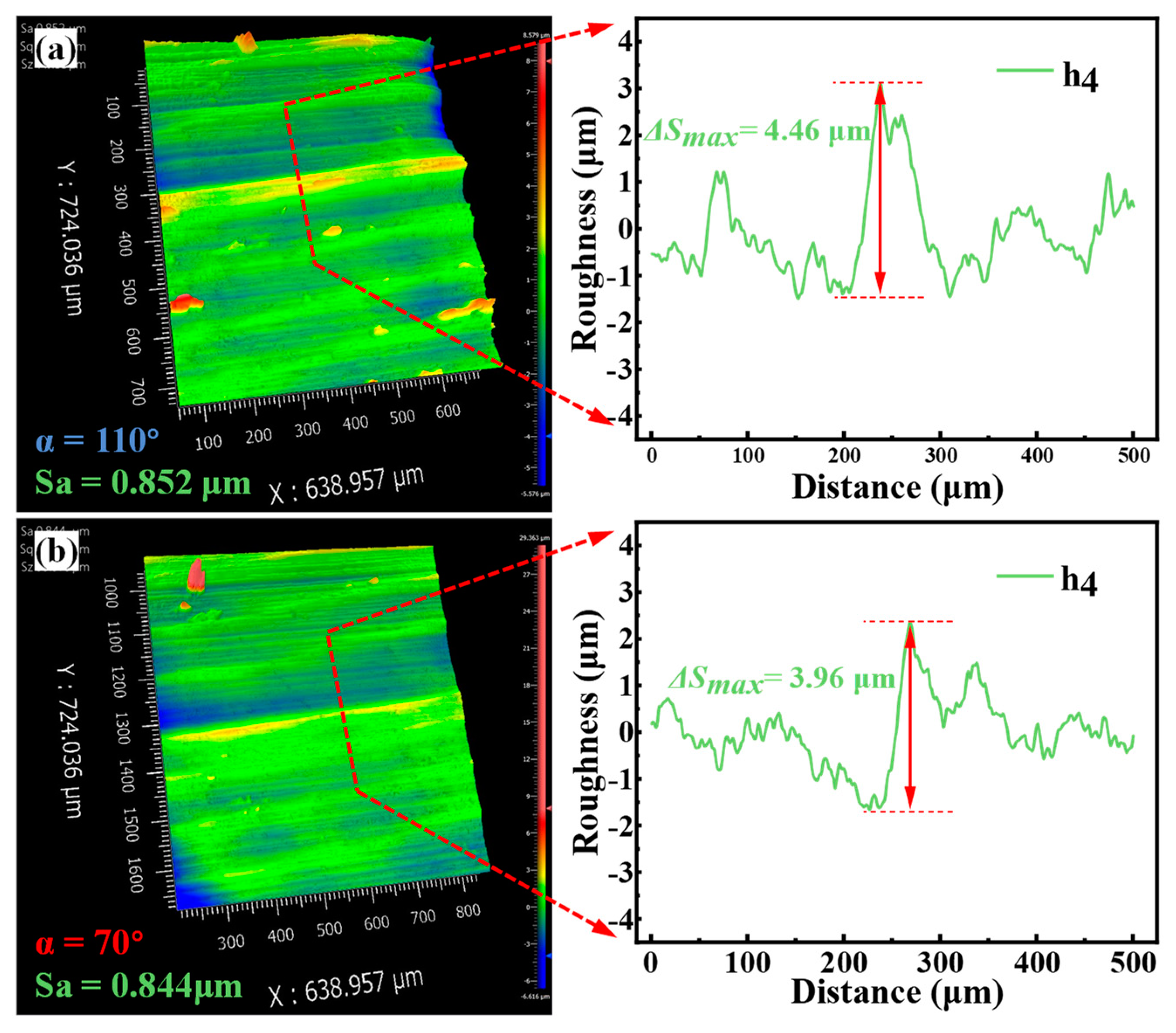
3.2.3. Surface Quality at Different Overhang Angle α
4. Conclusions
- Surface roughness and sinkage depth at the alternating interfaces can be reduced by adding shielding heights. With the increase of shielding heights from 0 mm to 0.5 mm, the surface roughness decreased from Sa 1.467 μm to Sa 0.857 μm, and the sinkage depth ΔSmax decreased from 7.62 μm to ΔSmax 3.39 μm, respectively. It provides a method for improving the surface quality of ASHM.
- For different hole diameters of 8 mm and 6 mm, by using the same shielding height, similar surface roughness and sinkage depth could be achieved, which indicates that a uniform surface quality in ASHM of different diameter holes could be obtained by using the same shielding height. Manufacturing parts of varying sizes using the ASHM process can utilize the same shielding height to attain a consistent surface quality.
- At a shielding height of 0.5 mm, surface roughness and sinkage depth were similar at the different overhang angles (70° and 110°) in the same overhang holes, which are Sa 0.844 μm and ΔSmax 3.96 μm, and Sa 0.852 and ΔSmax 4.46 μm, respectively. Within the same overhanging hole with varying overhang angles, the same shielding height can be used to achieve a uniform machined surface during the ASHM process.
Author Contributions
Funding
Data Availability Statement
Conflicts of Interest
References
- Zhang, W.X.; Hou, W.Y.; Deike, L.; Arnold, C. Understanding the Rayleigh instability in humping phenomenon during laser powder bed fusion process. Int. J. Extrem. Manuf. 2022, 3, 045201. [Google Scholar] [CrossRef]
- Chen, W.; Gu, D.D.; Yang, J.K.; Yang, Q.; Chen, J.; Shen, X. Compressive mechanical properties and shape memory effect of NiTi gradient lattice structures fabricated by laser powder bed fusion. Int. J. Extrem. Manuf. 2022, 4, 045002. [Google Scholar] [CrossRef]
- Wei, S.S.; Zhang, J.L.; Zhang, L.; Zhang, Y.J.; Song, B.; Wang, X.; Fan, J.; Liu, Q.; Shi, Y. Laser powder bed fusion additive manufacturing of NiTi shape memory alloys: A review. Int. J. Extrem. Manuf. 2022, 5, 032001. [Google Scholar] [CrossRef]
- Tan, C.L.; Deng, C.; Li, S.; Abena, A.; Jamshidi, P.; Essa, K.; Wu, L.; Xu, G.; Attallah, M.M.; Liu, J. Mechanical property and biological behaviour of additive manufactured TiNi functionally graded lattice structure. Int. J. Extrem. Manuf. 2022, 4, 045003. [Google Scholar] [CrossRef]
- Brandt, M.; Sun, S.J.; Leary, M.; Feih, S.; Elambasseril, J.; Liu, Q.C. High-Value SLM Aerospace Components: From Design to Manufacture. Adv. Mater. Res. 2013, 633, 135–147. [Google Scholar] [CrossRef]
- Sun, Q.S.; Xue, Z.X.; Chen, Y.; Xia, R.D.; Wang, J.; Xu, S.; Zhang, J.; Yue, Y. Modulation of the thermal transport of micro-structured materials from 3D printing. Int. J. Extrem. Manuf. 2022, 4, 015001. [Google Scholar] [CrossRef]
- Guo, N.; Leu, M.C. Additive Manufacturing: Technology, Applications and Research Needs. Front. Mech. Eng. 2013, 8, 215–243. [Google Scholar] [CrossRef]
- Flynn, J.M.; Shokrani, A.; Newman, S.T.; Dhokia, V. Hybrid Additive and Subtractive Machine Tools-Research and Industrial Developments. Int. J. Mach. Tools Manuf. 2016, 101, 79–101. [Google Scholar] [CrossRef]
- Olakanmi, E.O. Selective laser sintering/melting (SLS/SLM) of pure Al, Al-Mg, and Al-Si powders: Effect of processing conditions and powder properties. J. Mater. Process. Technol. 2013, 213, 1387–1405. [Google Scholar] [CrossRef]
- Balbaa, M.A.; Ghasemi, A.; Fereiduni, E.; Elbestawi, M.A.; Jadhav, S.D.; Kruth, J.P. Role of powder particle size on laser powder bed fusion processability of AiSi10mg alloy. Addit. Manuf. 2021, 37, 101630. [Google Scholar]
- Kalami, H.; Urbanic, J. Exploration of Surface Roughness Measurement Solutions for Additive Manufactured Components Built by Multi-axis Tool Paths. Addit. Manuf. 2021, 38, 101822. [Google Scholar] [CrossRef]
- Cebi, A.; Nesli, S.; Aslan, M.T.; Yilmaz, O.; Demirtas, H.; Subasi, L.; Gunaydin, A.; Bilgin, G.M.; Orhangul, A.; Akbulut, G. Surface characteristics of additively manufactured γ-TiAl intermetallic alloys post-processed by electrochemical machining. Surf. Interfaces 2024, 49, 104381. [Google Scholar] [CrossRef]
- Liu, H.; Ye, M.H.; Ye, Z.Y.; Wang, L.L.; Wang, G.; Shen, X.; Xu, P.; Wang, C. High-quality surface smoothening of laser powder bed fusion additive manufacturing AlSi10Mg via intermittent electrochemical polishing. Surf. Coat. Technol. 2022, 443, 128608. [Google Scholar] [CrossRef]
- Hung, W. Postprocessing of Additively Manufactured Metal Parts. J. Mater. Eng. Perform. 2021, 30, 6439–6460. [Google Scholar] [CrossRef]
- Du, W.; Bai, Q.; Zhang, B. A Novel Method for Additive/Subtractive Hybrid Manufacturing of Metallic Parts. Procedia Manuf. 2016, 5, 1018–1030. [Google Scholar] [CrossRef]
- Wang, Y.; Chen, Y.K.; Wen, C.Y.; Huang, K.; Chen, Z.; Han, B.; Zhang, Q. The process planning for additive and subtractive hybrid manufacturing powder bed (PBF) process. Mater. Des. 2023, 227, 111732. [Google Scholar] [CrossRef]
- He, Y.; Wei, J.C.; He, Y.Y.; Rong, X.X.; Guo, W.; Wang, F.; Wang, Y.; Liu, J. A process strategy planning of additive-subtractive hybrid manufacturing based multi-dimensional manufacturability evaluation of geometry feature. J. Manuf. Syst. 2023, 67, 296–314. [Google Scholar] [CrossRef]
- Amine, T.A.; Sparks, T.; Liou, F. A Strategy for Fabricating Complex Structures Via a Hybrid Manufacturing Process. In Proceedings of the 22nd Annual Solid Freeform Fabrication Symposium, Austin, TX, USA, 9–11 August 2011; pp. 175–184. [Google Scholar]
- Bai, Q.; Gao, Y.M.; Qiao, G.W.; Kang, R.K.; Zhang, Y.W. Adaptive Process Planning for Additive/Subtractive Hybrid Manufacturing of Overhang Features. J. Manuf. Sci. Eng. 2023, 145, 021010. [Google Scholar] [CrossRef]
- Sui, S.; Chew, Y.X.; Weng, F.; Tan, C.L.; Du, Z.; Bi, G. Study of the intrinsic mechanisms of nickel additive for grain refinement and strength enhancement of laser aided additively manufactured Ti-6Al-4V. Int. J. Extrem. Manuf. 2022, 4, 035101. [Google Scholar] [CrossRef]
- Ni, X.Q.; Kong, D.C.; Zhou, T.Q.; Zhang, L.; Wu, W.; Man, C.; Wu, W.; Dong, C. Heat treatment effects on the electrochemical behavior of pore-free Ti6Al4V ELI fabricated by laser powder bed fusion in fluoride-containing chloride solution. J. Alloys Compd. 2023, 937, 168439. [Google Scholar] [CrossRef]
- Leksycki, K.; Maruda, R.W.; Feldshtein, E.; Wojciechowski, S.; Habrat, W.; Gupta, M.; Królczyk, G.M. Evaluation of tribological interactions and machinability of Ti6Al4V alloy during finish turning under different cooling conditions. Tribol. Int. 2023, 189, 109002. [Google Scholar] [CrossRef]
- Ezugwu, E.O.; Bonney, J.; Yamane, Y. An overview of the machinability of aeroengine alloys. J. Mater. Process. Technol. 2003, 134, 233–253. [Google Scholar] [CrossRef]
- Fraooq, M.U.; He, M.A.Y.; Khan, A.M.; Pruncu, C.I.; Kashif, M.; Ahmed, N.; Asif, N. Curved profiles machining of Ti6Al4V alloy through WEDM: Investigations on geometrical errors. J. Mater. Res. Technol. 2020, 9, 16186–16201. [Google Scholar] [CrossRef]
- Wang, C.; Qian, X.; Gerstler, W.D.; Shubrooks, J. Boundary Slope Control in Topology Optimization for Additive Manufacturing: For Self-Support and Surface Roughness. J. Manuf. Sci. Eng. 2019, 141, 091001. [Google Scholar] [CrossRef]
- Qiao, G.W.; Zhang, B.; Guo, S.; Bai, Q.; Sun, Q.; Zhang, Y. Surface morphology in high-speed griding of TMCs fabricated by selective laser melting. J. Manuf. Process. 2023, 97, 200–209. [Google Scholar] [CrossRef]
- Wawrzyniak, N.; Wanjara, P.; Brochu, M.; Brochu, M. Measuring the tensile properties of Ti6Al4V fabricated by laser powder bed fusion: Influence of specimen dimensions. Theor. Appl. Fract. Mech. 2024, 131, 104419. [Google Scholar] [CrossRef]
- Phutela, C.; Aboulkhair, N.T.; Tuck, C.J.; Ashcroft, L. The Effects of Feature Sizes in Selectively Laser Melted Ti-6Al-4V Parts on the Validity of Optimised Process Parameters. Materials 2019, 13, 117. [Google Scholar] [CrossRef]
- Cerri, E.; Ghio, E.; Bolelli, G. Effect of surface roughness and industrial heat treatments on the microstructure and mechanical properties of Ti6Al4V alloy manufactured by laser powder bed fusion in different built orientations. Mater. Sci. Eng. A 2022, 851, 143635. [Google Scholar] [CrossRef]
- Morgan, R.H.; Papworth, A.J.; Sutcliffe, C.; Fox, P.; O’Neill, W. High Density Net Shape Components by Direct Laser Re-Melting of Single-Phase Powders. J. Mater. Sci. 2002, 37, 3093–3100. [Google Scholar] [CrossRef]
- Wang, D.; Yang, Y.Q.; Yi, Z.H.; Su, X.B. Research on the fabricating quality optimization of the overhanging surface in SLM process. Int. J. Adv. Manuf. Technol. 2013, 65, 1471–1484. [Google Scholar] [CrossRef]


| Parameters | L (mm) | α (°) | D (mm) | A (mm) | B (mm) |
| Value | 10 | 70, 110 | 6, 8 | 10 | 10 |
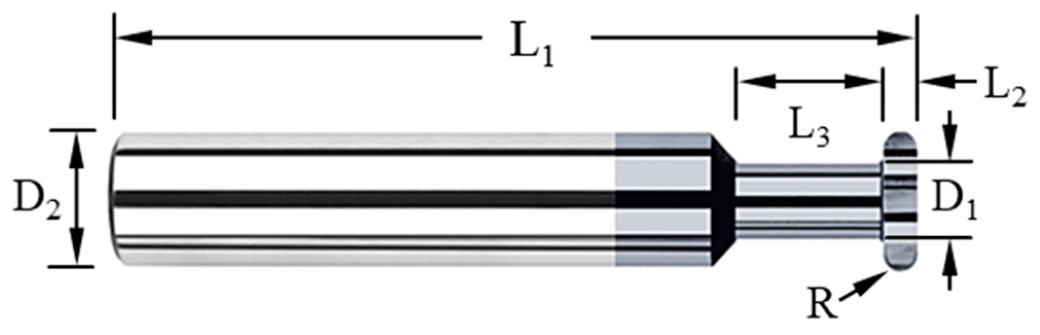
| Parameters | L1 | L2 | L3 | D1 | D2 | R |
| Value | 50 | 1 | 5 | 2.5 | 4 | 0.5 |
| Elements | Ti | Al | V | Fe | C | O | V | N |
| (wt.%) | Bal | 6.04 | 4.1 | 0.15 | 0.014 | 0.06 | 0.11 | 0.011 |
| Parameters | Value |
|---|---|
| Laser power, P (W) | 260 |
| Spot diameter, d0 (μm) | 200 |
| Layer thickness, d (μm) | 50 |
| Laser scanning speed, v (mm/s) | 900 |
| Spindle speed, r (rpm) | 35,000 |
| Feed rate, vf (mm/min) | 500 |
Disclaimer/Publisher’s Note: The statements, opinions and data contained in all publications are solely those of the individual author(s) and contributor(s) and not of MDPI and/or the editor(s). MDPI and/or the editor(s) disclaim responsibility for any injury to people or property resulting from any ideas, methods, instructions or products referred to in the content. |
© 2024 by the authors. Licensee MDPI, Basel, Switzerland. This article is an open access article distributed under the terms and conditions of the Creative Commons Attribution (CC BY) license (https://creativecommons.org/licenses/by/4.0/).
Share and Cite
Liu, Y.; Liu, W.; Zhang, Y.; Guan, F.; Xue, X.; Zheng, Y.; Bai, Q. Study on the Surface Quality of Overhanging Holes Fabricated by Additive/Subtractive Hybrid Manufacturing for Ti6Al4V Alloy. Metals 2024, 14, 979. https://doi.org/10.3390/met14090979
Liu Y, Liu W, Zhang Y, Guan F, Xue X, Zheng Y, Bai Q. Study on the Surface Quality of Overhanging Holes Fabricated by Additive/Subtractive Hybrid Manufacturing for Ti6Al4V Alloy. Metals. 2024; 14(9):979. https://doi.org/10.3390/met14090979
Chicago/Turabian StyleLiu, Yanmei, Weijian Liu, Yingwei Zhang, Feng Guan, Xiong Xue, Yongsheng Zheng, and Qian Bai. 2024. "Study on the Surface Quality of Overhanging Holes Fabricated by Additive/Subtractive Hybrid Manufacturing for Ti6Al4V Alloy" Metals 14, no. 9: 979. https://doi.org/10.3390/met14090979