Abstract
High-entropy alloys (HEAs) have emerged as a novel class of materials with exceptional mechanical and corrosion properties, offering promising applications in various engineering fields. However, optimizing their performance through advanced manufacturing techniques, like laser cladding, remains an area of active research. This study investigated the effects of laser energy density on the mechanical and electrochemical properties of CoCrFeMnNi HEA coatings applied to Q235 substrates. Utilizing X-ray diffraction (XRD), this study confirmed the formation of a single-phase face-centered cubic (FCC) structure in all coatings. The hardness of the coatings peaked at 210 HV with a laser energy density of 50 J/mm2. Friction and wear tests highlighted that a coating applied at 60 J/mm2 exhibited the lowest wear rate, primarily due to adhesive and oxidative wear mechanisms, while the 55 J/mm2 coating showed increased hardness but higher abrasive wear. Electrochemical testing revealed superior corrosion resistance for the 60 J/mm2 coating, with a slow corrosion rate and minimal passivation tendency in contrast to the 55 J/mm2 coating. The comprehensive evaluation indicates that the HEA coating with an energy density of 60 J/mm2 exhibits exceptional wear and corrosion resistance.
1. Introduction
High-entropy alloys (HEAs) [1,2] have emerged as a prominent area of research in materials science due to their multi-principal element composition, typically including five or more elements and distinctive microstructures. These alloys are noted for their exceptional wear and corrosion resistance, which have attracted significant attention in recent years. The remarkable properties of HEAs are largely due to a synergistic combination of effects: the high-entropy effect, lattice distortion, slow diffusion, and the cocktail effect [3]. Among the various HEA systems, the CoCrFeMnNi alloy is particularly noteworthy for its stable single-phase face-centered cubic (FCC) structure, which confers superior ductility and machinability [4].
The production of HEAs can be achieved through several fabrication methods, including solid mixing, liquid mixing, and gas mixing [5]. To improve the surface characteristics of these materials, a range of surface modification techniques has been utilized. These include high-velocity oxygen fuel spraying [6,7], magnetron sputtering [6], plasma spraying, cold spraying [8,9], chemical plating [10], and electrodeposition [11]. Despite their potential, these methods can be constrained by inadequate metallurgical bonding between the coating and the substrate. Laser cladding, a specific liquid-mixing technique, addresses these constraints effectively. It is a process that utilizes a high-energy-density laser beam as a heat source to melt alloy powders or wires and deposit them onto the surface of a substrate, thereby forming a cladding layer with specific properties. Compared to traditional techniques, such as thermal spraying and electroplating, laser cladding has advantages such as a higher utilization rate of cladding materials, excellent directionality, and smaller heat-affected zones. The process results in a robust metallurgical bond with the substrate and enables the creation of thicker coatings (≥1 mm). Q235 steel is renowned for its balanced mechanical properties; however, it exhibits limitations under extreme environmental conditions characterized by increased wear and corrosive media, which hinders its suitability for long-term applications. HEA coatings can provide reinforcement and repair functions for Q235 steel, significantly enhancing its wear resistance, corrosion resistance, and substantially extending the service life of the associated components.
The effectiveness of laser-clad coatings hinges on the precise selection of process parameters, with the laser power, powder feeding rate, and scanning speed being particularly critical [12]. Adequate control over these variables is essential to achieve the desired coating characteristics. The thermal input to the substrate, a function of laser power and scanning speed, profoundly impacts the coating’s surface quality and dilution rate [13]. Elevated scanning speeds can curtail thermal input, thus preserving the uniformity of the coating’s composition. Additionally, the overlap rate and powder feeding rate are pivotal in shaping the geometric profile of the coating. While considerable advancements have been noted in the investigation of scanning speed, particularly in extreme high-speed laser cladding scenarios [6,12,14,15,16,17], research into laser power parameters remains somewhat limited [12].
In previous studies, among the three key parameters of laser cladding (scanning speed, laser power, and powder feeding rate), laser power has demonstrated a particularly significant impact on the mechanical properties of coatings. Yi Zhang and colleagues [18] analyzed the impact of process parameters on the performance of coatings, employing the non-dominated sorting genetic algorithm II for optimization and validation. Their findings demonstrate that laser power predominantly affects the coating’s dilution rate. In a parallel investigation focused on the laser cladding of AlCoCrFeNi2.1 eutectic HEAs, Zhen Dong, and co-workers [19] conducted preliminary tests, systematically altering individual process parameters. Their results underscore the intimate relationship between coating porosity, microhardness, and the respective process parameters. Specifically, microhardness was inversely related to laser power and directly related to the scanning speed and powder feeding rate. Zhen Dong et al. [20] utilized a single-variable control method to optimize the laser cladding process for AlCoCrFeNi2.1 eutectic HEA, revealing that laser power predominantly influences the coating’s microhardness. Similarly, Sha Wu et al. [21] applied a central composite design response surface methodology to Ni60A-25% tungsten carbide (WC) powder, concluding that laser power is the most influential factor in the dilution rate. Yuling Gong et al. [22] identified laser power, scanning speed, powder feeding rate, and spot diameter as the primary determinants of cladding width.
This research systematically investigates the mechanical and chemical properties of CoCrFeMnNi HEA coatings applied to a Q235 substrate via laser cladding. By varying the laser power and utilizing three distinct laser energy densities, this study assessed the hardness, tribological performance, and corrosion resistance of the coatings. The wear behavior was evaluated under a constant 50 N load across the different energy densities. Additionally, the coatings were subjected to dynamic potentiodynamic polarization and electrochemical impedance spectroscopy (EIS) analyses in a 3.5 wt% NaCl solution to understand their corrosion resistance further. This study offers a novel perspective on understanding how laser power affects the performance of coatings through variations in energy density.
2. Experimental Procedures
2.1. Preparation of the HEA Coatings
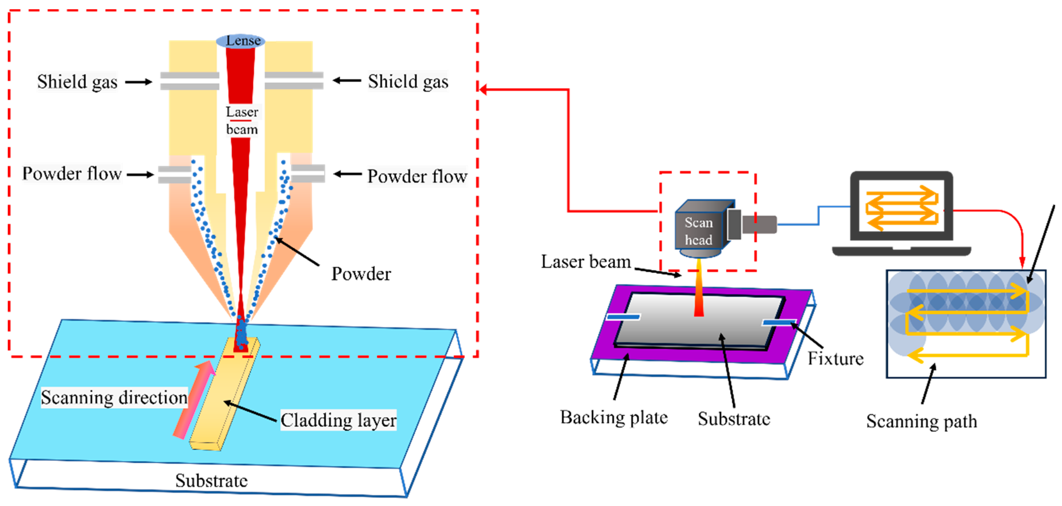
In this study, Q235 steel served as the substrate material, and the CoCrFeMnNi HEA was fabricated using plasma-atomized metal powders with an equimolar atomic ratio of 1:1:1:1:1. The chemical composition of both the substrate and the HEA powder is detailed in Table 1. The applied coating was designed to have a nominal thickness of approximately 1 mm. The specific parameters for the laser process are outlined in Table 2. Argon gas, with a purity of 99.999 wt% and a flow rate of 25 mL/min, was employed as a shielding medium to maintain an oxygen concentration below 0.01% during the coating formation, thereby mitigating potential oxidation. Figure 1 illustrates the schematic representation of the laser cladding setup and the scanning strategy.

Table 1.
Chemical composition of substrate and CoCrFeMnNi coatings in wt%.
Table 2.
List of the experiment design scheme and corresponding laser cladding process parameter.
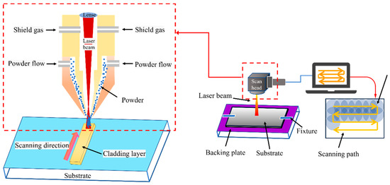
Figure 1.
Schematic diagram of laser cladding.
To investigate the influence of laser energy density on the properties of the coatings, our experimental design incorporated three distinct laser powers: 3200 W, 3500 W, and 3800 W. Table 2 provides a summary of the calculated laser energy densities (ES), which were derived using the following Formula (1) [23]:
where P is the laser power (W), D is the laser spot diameter (mm), and v is the laser scanning speed (mm/s). Studies have demonstrated that an increased ES can result in excessive substrate melting, which may negatively impact the performance of the laser-clad coatings. In contrast, a lower ES facilitates the formation of solid solutions, enhancing the coating’s characteristics. Nonetheless, a decrease in ES enhances the likelihood of glass phase formation with amorphous structures, which could compromise the microstructure quality and the adhesion between the substrate and the coating. Consequently, it is imperative to maintain ES within an optimal range to balance these effects. Additionally, these power settings allowed us to explore the relationship between the laser power, coating thickness, and formability, adhering to prior research indications that suggested a decrease in formability above 4.0 kW [13]. This approach ensured a comprehensive analysis of the effect of laser energy density on deposition.
2.2. Characterization of Microstructures
In this research, X-ray diffraction (XRD) analysis was conducted to ascertain the phase structure of the coating, with a scanning angle ranging from 30° to 100°. A Cu Kα radiation source (λ = 1.5406 Å) was used, applying a voltage of 40 kV and a current of 30 mA, with scanning at a rate of 4°/min. The surface morphology and compositional information of the coating were meticulously examined. This was accomplished using a field-emission scanning electron microscope (ZEISS Gemini SEM 300, ZEISS, Oberkochen, Germany) equipped with an In-lens secondary electron detector (In-lens SE, ZEISS, Oberkochen, Germany) and an energy-dispersive spectrometer (EDS). Furthermore, high-resolution confocal microscopy was applied to assess the surface morphology and roughness, facilitating a comprehensive three-dimensional imaging analysis.
2.3. Property Tests
2.3.1. Microhardness
In this study, the microhardness of HEA coatings and their substrates was evaluated using a Vickers hardness tester (HV-1000, Shidai Yiqi, Beijing, China). The tests were conducted at a constant load of 200 g for 15 s at each point, ensuring the test conditions met the environmental requirements specified in the standard [24]. The measurements were taken at intervals of 50 µm from the surface of the coating downwards in the coating cross-section. To confirm the precision and reproducibility of the hardness measurements, the testing procedure was meticulously repeated on three separate occasions, adhering to identical process parameters.
2.3.2. Friction and Wear Testing
Coatings were tested for the dry sliding wear of the ball and disk by MFT-5000 rotational friction and wear tester in a dry environment. A SiC ball with a diameter of 5 mm was used in the test; the rotational speed was set to 30 mm/s, a load of 50 N was applied, and the friction duration was 1200 s. After wear, the mass loss of the samples was measured using a YTL1204 electronic balance (0.1 mg), and the morphology of the wear tracks and the chemical composition of the abrasive chips were analyzed by SEM and EDS. Each experimental parameter was repeated three times to ensure the accuracy and reproducibility of the data.
2.3.3. Electrochemical Test
The corrosion resistance of materials was assessed using electrochemical methods, with the potentiodynamic polarization curves of the high-entropy alloy (HEA) coatings being recorded on a CS310 electrochemical workstation employing a standard three-electrode configuration. Before testing, the surface of each sample was meticulously ground to a 2400-grit finish using SiC paper, standardizing the surface’s condition across all samples. In the electrochemical cell, the test sample, a platinum sheet, and a saturated calomel electrode (SCE) served as the working, counter, and reference electrodes. Once the open circuit potential (OCP) reached stabilization, the polarization measurements were conducted within a potential range of −0.2 to 1.4 V at a scanning rate of 0.5 mV/s. The electrochemical impedance spectroscopy (EIS) data were modeled using an equivalent circuit in Zview software (Zview2), with the resulting impedance values depicted on an isometric Nyquist plot for visualization. Subsequently, potentiostatic polarization tests were performed in a 3.5 wt% NaCl solution for 1 h, utilizing distinct samples for each trial. All the tests were conducted at 25 °C and repeated three times to confirm reproducibility.
3. Results and Discussion
3.1. XRD Analysis
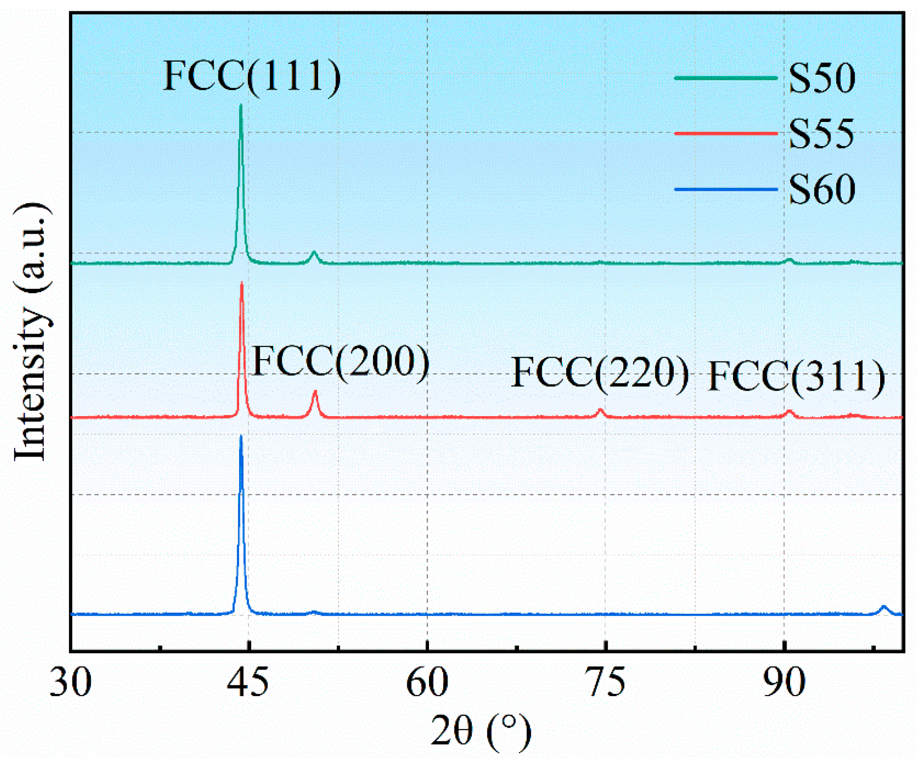
Figure 2 illustrates the XRD test results of the CoCrFeMnNi HEA coating. The test results show that the CoCrFeMnNi HEA coating consists of a single FCC solid solution phase. For S55, the diffraction peaks mainly appeared at angles of 44.4°, 50.4°, 74.1° and 90°. Compared with S55, the diffraction peaks of S50 and S60 showed a tendency to shift to lower angles and were concentrated at 44.4° with stronger diffraction peaks. These stronger diffraction peaks may indicate that the crystals have a higher degree of orientation in this direction [25]. Compared to S50 and S60, the grain orientation of S55 is more uniform. Figure 2 exclusively shows a diffraction peak for S60 at 100°. This phenomenon could be due to the elevated energy density promoting specific grain orientations. The increased energy aids in surmounting nucleation barriers for certain crystal planes, enhancing their growth and resulting in more pronounced diffraction peaks. Conversely, S55 and S50, with their reduced energy density, display suboptimal crystal development. The energy density significantly influences both the growth and orientation of crystals. Consequently, it shapes the distinctive features observed in the XRD pattern.
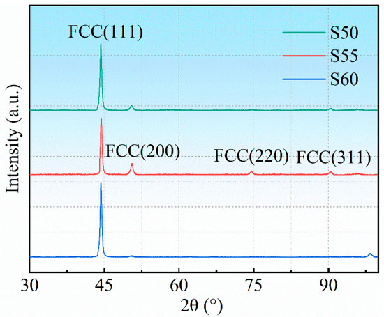
Figure 2.
XRD patterns of S50, S55, and S60.
3.2. Properties Analysis
3.2.1. Hardness
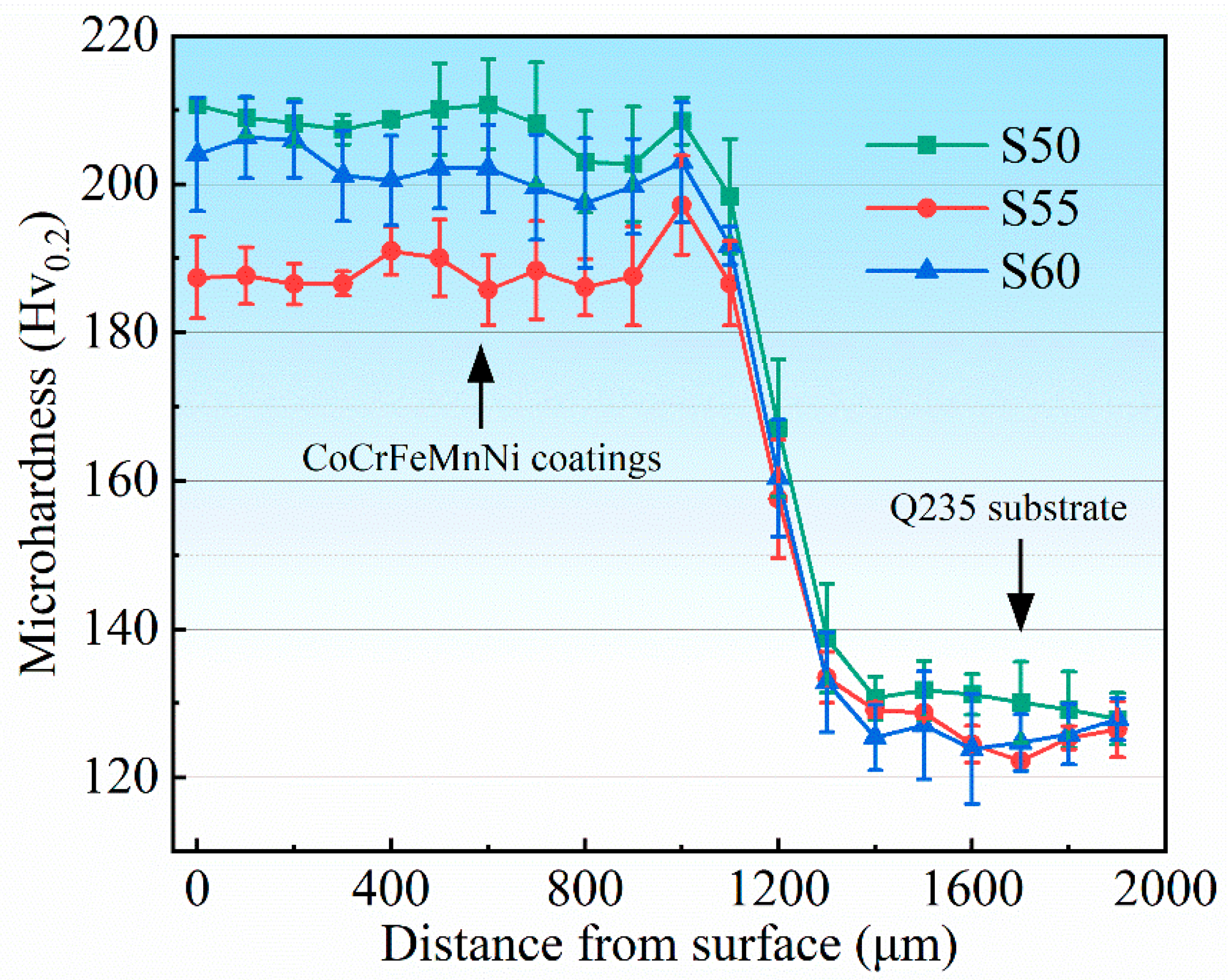
Figure 3 shows the hardness measurements of the HEA coating in this study. The results show that the hardness values of the coatings fluctuated between 180 HV and 220 HV. The coatings with different energy densities did not show significant differences in microhardness. Specifically, the S50 coating showed the highest hardness with a stabilized hardness value of about 210 HV. In the transition region between the coating and the substrate, the hardness value fluctuated around 160 HV due to material intercalation. In addition, a study by Zhang et al. [24] in the literature noted that the hardness of unprocessed HEA coatings typically ranged from 150 to 190 HV, similar to the range of coating hardness values in this study. Under conditions of reduced energy density, the cladding layer potentially contains residual unmelted powder particles. The presence of these particles can enhance the hardness of the coating. As the energy density is incrementally increased, the temperature within the melt pool rises, promoting thorough powder melting. Consequently, the diminished presence of unmelted particles results in a reduction in the coating’s hardness. Further increments in energy density ensure complete powder melting, leading to microstructural refinement and the homogenization of elemental diffusion. These effects collectively contribute to an increase in the hardness of the coating.

Figure 3.
Microhardness of S50, S55, S60, and substate.
3.2.2. Wear Behavior
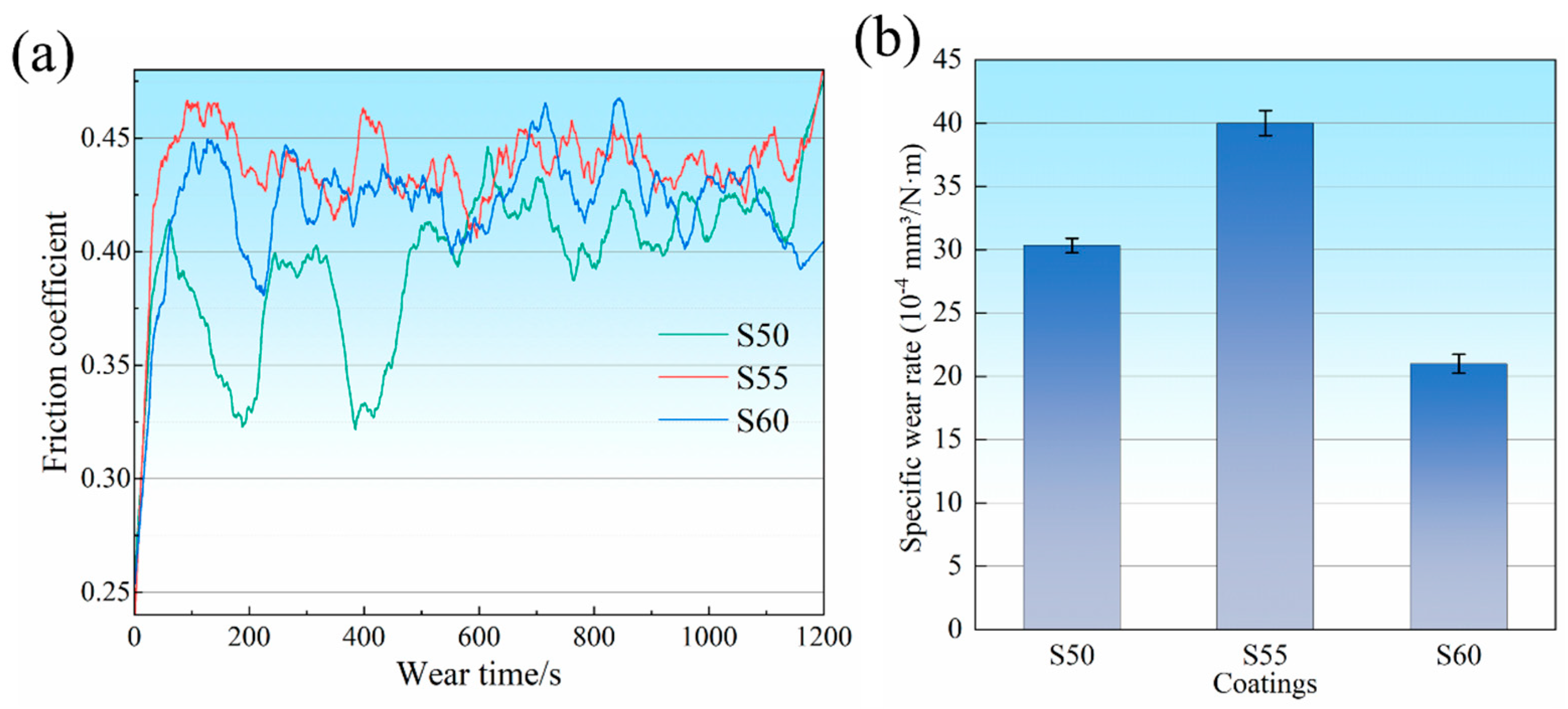
Figure 4a illustrates a plot of friction coefficient versus time for HEA coatings. The plot reveals the dynamic change in the friction coefficient during the friction process. The friction coefficient of the coating increases rapidly during the initial friction stage and then gradually stabilizes. At the initial stage of friction, the process shows significant instability due to the high surface roughness and adhesion [26]. For the duration of the sliding progress, the protruding surface features gradually undergo smoothing, resulting in a concomitant increase in the contact area. This phenomenon culminates in stabilizing the friction coefficient for both the S55 and S60 coatings, effectively indicating that they have reached a state of equilibrium [27,28]. The friction coefficient of the S50 coating, which is the lowest overall among the three parameters, shows instability during the first 600 s of the friction time. This instability may be related to localized fracture and the accumulation of debris in the surface layer of the coating. In contrast, the coefficient of friction of the S60 coating was stable between 0.40 and 0.45, showing better friction resistance. Figure 4b shows the specific wear rate of the coatings after 1200 s of rotational wear at a 50 N load. There was not much difference in the specific wear rate of the three coatings. According to Archard’s wear theory [29], microhardness positively correlates with wear resistance. However, in this study, the S60 coating with intermediate microhardness exhibited the lowest specific wear rate, possibly related to its special wear morphology. The coefficient of friction curves and specific friction rate results show that the S60 coating exhibits the best friction resistance.

Figure 4.
(a) Friction coefficient–time graphs and (b) specific wear rate of coatings after friction and wear under a load of 50 N.
Figure 5a–c show the friction wear topographies of the three coatings after rotational wear under a 50 N load for 1200 s, which can be roughly analyzed for the wear mechanism of the coatings. The 3D topographies of S50 show that there is a part of the bulge at the bottom of the scratch (Figure 5(a1)), and there is a uniform arrangement of extruded material on both sides of the scratch, which suggests that the process of removing the material is relatively stable [20,30]. A small number of surface cracks and abrasive chips can be observed in the SEM image (Figure 5(a2)), and it is assumed that the wear mechanism is slightly adhesive wear [27,31,32,33]. In contrast, S55 has a small number of grooves on the wear surface, and the depth of scratches is larger than that of S50 and S60 in Figure 5(b1), which may be one of the reasons for its higher wear rate. In conjunction with Figure 5(b2), some fine scratches can be found on the wear surface, which may be related to three-body wear. Compared with Figure 5(a2), no obvious abrasive chips were found, but some surface cracks were present, so it is presumed that the wear mechanism indicates abrasive wear [32]. Obvious furrows [28] can be observed in the macroscopic morphology map of S60 (Figure 5(c1)), and they are extruded with uneven material on both sides of the furrows. Obvious surface delamination and abrasive debris can be observed from its SEM image in Figure 5(c2). It is presumed that there is material spalling and transferring during frictional wear and there is adhesive wear [34,35]. The formation process of furrows extruded the material, but the material was not completely detached, so its specific friction rate was lower. Compared to S50 and S55, S60 showed clear delamination boundaries, indicating oxidative wear on the coating. The wear mechanism can be determined by analyzing the wear grooves and abrasive debris on the dyadic material by EDS point scanning. The results of the correlation analysis are summarized in Table 3. The results show that the high O content in the wear recesses indicates that oxidative wear plays a role in the wear process [36]. The low C and Si content is due to the partial retention of SiC spheres on the wear surface. In addition, the composition of the CoCrFeMnNi HEA coating detected on the dyadic material suggests that slight adhesive wear may have occurred.
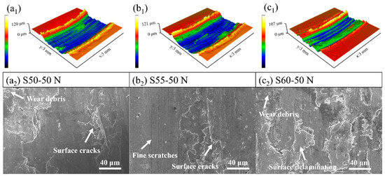
Figure 5.
The 3D morphology of (a1) S50; (b1) S55; (c1) S60 and SEM images (a2) S50; (b2) S55; and (c2) S60 of wear scars tested under a load of 50 N.
Table 3.
Chemical composition of wear debris in various wear areas and dual materials under 50 N (wt%).
3.2.3. Electrochemical Corrosion
To investigate the corrosion resistance of CoCrFeMnNi HEA with different powers, dynamic potentiodynamic polarization and electrochemical impedance spectroscopy (EIS) tests were carried out in a 3.5 wt% NaCl solution. Figure 6 shows the electrochemical analysis test plots of CoCrFeMnNi HEA coatings prepared by laser melting with different powers. Figure 6a shows the dynamic polarization curves of the three CoCrFeMnNi coatings. The corrosion potential (Ecorr) and corrosion current density (icorr) on the y-axis were determined by the intersection point using the Tafel extrapolation method, as shown in Table 4. The corrosion rate (CR) was calculated from the potentiodynamic data as follows:
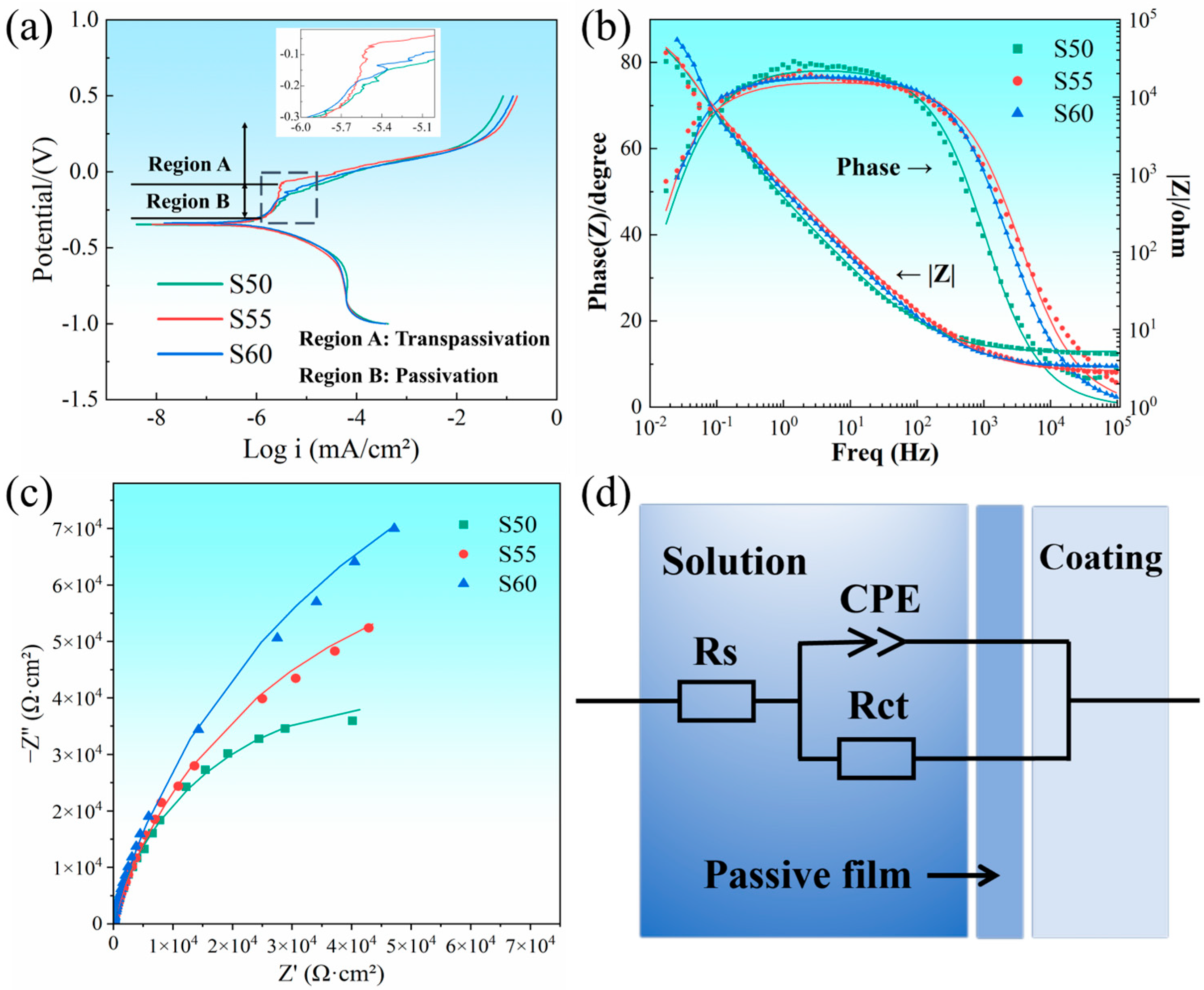
where K is a constant (3272 mm × amp−1 × cm−1 × year−1), EW is the equivalent weight in grams/equivalent, A is the sample area (cm²), and ρ is the sample density [4,32,36,37]. The Icorr of S60 was reduced by an order of magnitude compared to the other two coatings. From the viewpoint of corrosion kinetics and corrosion thermodynamics, S60 has a slow corrosion rate, good corrosion resistance, and low corrosion tendency. Among the three parameters, only S55 underwent significant passivation [38].

Figure 6.
Electrochemical test analysis of S50, S55, and S60: (a) potentiodynamic polarization curves; (b) Bode diagram; (c) Nyquist diagram; and (d) equivalent circuit diagrams.
Table 4.
Fitting parameters of potentiodynamic polarization curves.
Figure 6b shows the Bode plot, which demonstrates the variation in the impedance modulus |Z| and phase angle with frequency. S60 has a broader phase angle plateau in the mid-frequency band, indicating that S60 has better corrosion resistance. As shown in Figure 6b, S60 has the largest impedance modulus in the low-frequency region, indicating that this sample has a better charge transfer resistance [39]. As shown in Figure 6c, all specimens exhibit similar pressed capacitance semicircle Nyquist plots, with the semicircle radius indicating the charge transfer resistance, reflecting the difference in corrosion resistance of CoCrFeMnNi HEAs with different microstructures. The corrosion resistance was evaluated by comparing the magnitude of the impedance arcs in Figure 6c. The higher the arc impedance, the better the corrosion resistance; thus, Figure 6c verifies that S60 has better corrosion resistance. The equivalent circuit used to fit the EIS data is shown in Figure 6d, which consists of a resistor (RP) and a constant phase element (CPE) [9,40]. The former is used to fit the polarization resistance of the working electrode, and the latter is used to characterize the double-layer charge capacitance adsorbed on the sample surface. The electrolyte resistance is noted as RS.
4. Conclusions
In summary, three different laser energy densities were used to laser-melt the CoCrFeMnNi HEA coatings on the surface of the Q235 substrate. The mechanical and electrochemical properties of the coatings as a function of energy density were elucidated by XRD analysis, microhardness testing, friction and wear testing, and electrochemical testing.
- The CoCrFeMnNi HEA coating consists of a single FCC phase with the strongest peaks in the low-angle diffraction peaks, and the crystals are highly oriented in that direction. The increase in energy density significantly affects the microhardness, with a difference of 20 HV between the highest average hardness (S50, 210 HV) and the lowest average hardness (S55, 190 HV).
- The lowest hardness, S50, also showed better friction performance, but its friction process was unstable. Combining several indicators, S60 has the best friction resistance, and its main wear mechanism is delamination wear. A decrease in energy density enhances the hardness of the coating while decreasing the surface toughness, which inhibits the adhesive wear of the HEA coating. S55 is mainly dominated by three-body wear, and its specific friction rate is the highest. Oxidized wear generated by frictional heat was prevalent in all three coatings.
- In electrochemical tests, S60 had a slow corrosion rate, good corrosion resistance, and low corrosion tendency. Among these three parameters, only S55 experienced significant passivation.
Therefore, the selection of a reasonable energy density is essential to optimize the mechanical properties of the coating. However, it is more important to understand the effect of energy density variations on coating properties in order to select the appropriate process parameters to suit specific application scenarios under different application requirements.
Author Contributions
Conceptualization, Y.L. and C.D.; methodology, Q.Z. and S.S.; software, C.D. and Q.Z.; validation, Q.Z. and S.S.; formal analysis, X.W. (Xiao Wang) and H.N.; investigation, X.W. (Xiao Wang) and X.W. (Xiaofeng Wan); resources, H.N. and X.W.; data curation, H.W. and S.S.; writing—original draft preparation, C.D., Y.L. and X.W. (Xiaofeng Wan); writing—review and editing, C.D. and X.W. (Xiao Wang); visualization, H.W. and S.S.; supervision, Y.L. and H.W. All authors have read and agreed to the published version of the manuscript.
Funding
This research was supported by the Priority Academic Program Development of Jiangsu Higher Education Institutions (PAPD), the Jiangsu Innovation Support Program (International Science and Technology Cooperation) Project (grant number BZ2023002), the Natural Science Horizontal Research Project of Nantong University (grant No. 22ZH643), the Key R&D Projects of Jiangsu Province (BE2023765), Postgraduate Research & Practice Innovation Program of Jiangsu Province (KYCX24_3554), the Analysis and Test Centre of Nantong University and the Analysis, and the Testing Center of NUAA.
Data Availability Statement
The original contributions presented in the study are included in the article, further inquiries can be directed to the corresponding authors.
Conflicts of Interest
No conflicts of interest exit in the submission of this manuscript, and the manuscript was approved by all authors for publication.
References
- Cantor, B.; Chang, I.T.H.; Knight, P.; Vincent, A.J.B. Microstructural development in equiatomic multicomponent alloys. Mater. Sci. Eng. A-Struct. Mater. Prop. Microstruct. Process. 2004, 375, 213–218. [Google Scholar] [CrossRef]
- Heydartaemeh, M.; Karamoozian, M.; Potgieter, H. Application of Nano High-Entropy Alloys to Reduce Energy Consumption and Wear of Copper Oxide and High-Grade Iron Ores in Heavy Mining Industries—A Case Study. Minerals 2020, 10, 16. [Google Scholar] [CrossRef]
- Wen, X.; Cui, X.; Jin, G.; Zhang, X.; Zhang, Y.; Zhang, D.; Fang, Y. Design and characterization of FeCrCoAlMn0.5Mo0.1 high-entropy alloy coating by ultrasonic assisted laser cladding. J. Alloys Compd. 2020, 835, 155449. [Google Scholar] [CrossRef]
- Jin, X.; Gu, X.; Quan, F.; Ran, X.; Zhang, K.; Mao, A. CoCrFeMnNi high-entropy alloy powder with excellent corrosion resistance and soft magnetic property prepared by gas atomization methodGasverdustes CoCrFeMnNi Hoch-Entropie Legierungspulver mit hervorragender Korrosionsbestandigkeit und weichmagnetischen Eigenschaften. Mater. Werkst. 2019, 50, 837–843. [Google Scholar] [CrossRef]
- Arif, Z.U.; Khalid, M.Y.; Rehman, E.U.; Ullah, S.; Atif, M.; Tariq, A. A review on laser cladding of high-entropy alloys, their recent trends and potential applications. J. Manuf. Process. 2021, 68, 225–273. [Google Scholar] [CrossRef]
- Zhou, J.; Cheng, Y.; Chen, Y.; Liang, X. Composition design and preparation process of refractory high-entropy alloys: A review. Int. J. Refract. Met. Hard Mater. 2022, 105, 105836. [Google Scholar] [CrossRef]
- Addepalli, S.N.; Joladarashi, S.; Ramesh, M.R. Elevated temperature tribological performance of non-equiatomic CoCrNiTiWx high entropy alloy coatings developed by mechanical alloying and high-velocity oxy-fuel spray. Surf. Coat. Technol. 2024, 476, 130267. [Google Scholar] [CrossRef]
- Luo, D.; Zhou, Q.; Huang, Z.; Li, Y.; Liu, Y.; Li, Q.; He, Y.; Wang, H. Tribological Behavior of High Entropy Alloy Coatings: A Review. Coatings 2022, 12, 1428. [Google Scholar] [CrossRef]
- Aliyu, A.; Srivastava, C. Phase constitution, surface chemistry and corrosion behavior of electrodeposited MnFeCoNiCu high entropy alloy-graphene oxide composite coatings. Surf. Coat. Technol. 2022, 429, 127943. [Google Scholar] [CrossRef]
- Yang, H.; Tang, Z.; Wan, L.; Wei, Q.; Wu, J.; Wang, A.; Jin, X.; Li, X.; Wu, Y.; Lu, G.; et al. Achieving crack-free CuCrZr/AlSi7Mg interface by infrared-blue hybrid laser cladding with low power infrared laser. J. Alloys Compd. 2023, 931, 167572. [Google Scholar] [CrossRef]
- Ma, G.; Zhao, Y.; Cui, H.; Song, X.; Wang, M.; Lee, K.; Gao, X.; Song, Q.; Wang, C. Addition Al and/or Ti Induced Modifications of Microstructures, Mechanical Properties, and Corrosion Properties in CoCrFeNi High-Entropy Alloy Coatings. Acta Metall. Sin. Engl. Lett. 2021, 34, 1087–1102. [Google Scholar] [CrossRef]
- Liang, Y.; Liao, Z.Y.; Zhang, L.L.; Cai, M.W.; Wei, X.S.; Shen, J. A review on coatings deposited by extreme high-speed laser cladding: Processes, materials, and properties. Opt. Laser Technol. 2023, 164, 109472. [Google Scholar] [CrossRef]
- Shu, F.; Zhang, B.; Liu, T.; Sui, S.; Liu, Y.; He, P.; Liu, B.; Xu, B. Effects of laser power on microstructure and properties of laser cladded CoCrBFeNiSi high-entropy alloy amorphous coatings. Surf. Coat. Technol. 2019, 358, 667–675. [Google Scholar] [CrossRef]
- Du, C.; Hu, L.; Ren, X.; Li, Y.; Zhang, F.; Liu, P.; Li, Y. Cracking mechanism of brittle FeCoNiCrAl HEA coating using extreme high-speed laser cladding. Surf. Coat. Technol. 2021, 424, 127617. [Google Scholar] [CrossRef]
- Du, J.L.; Xu, X.; Zhang, H.M.; Lu, M.W.; Sun, J.F.; Luo, K.Y.; Lu, J.Z. Microstructure and wear resistance of CoCrFeNiMn coatings prepared by extreme-high-speed laser cladding. Surf. Coat. Technol. 2023, 470, 129821. [Google Scholar] [CrossRef]
- Zhou, L.; Ma, G.; Zhao, H.; Mou, H.; Xu, J.; Wang, W.; Xing, Z.; Li, Y.; Guo, W.; Wang, H. Research status and prospect of extreme high-speed laser cladding technology. Opt. Laser Technol. 2024, 168, 109800. [Google Scholar] [CrossRef]
- Xu, Q.-L.; Liu, K.-C.; Wang, K.-Y.; Lou, L.-Y.; Zhang, Y.; Li, C.-J.; Li, C.-X. TGO and Al diffusion behavior of CuAlxNiCrFe high-entropy alloys fabricated by high-speed laser cladding for TBC bond coats. Corros. Sci. 2021, 192, 109781. [Google Scholar] [CrossRef]
- Zhang, Y.; Bai, P.; Li, Z.; Zhang, J.; Liu, W. Multi-Objective optimization of laser cladding process parameters for Q345B steel. Mater. Today Commun. 2024, 39, 108679. [Google Scholar] [CrossRef]
- Dong, Z.; Feng, L.; Long, H.; Lu, B.; Zhu, J.; Yan, X.; Ma, R.; Qiu, C.; Gui, Y.; Liu, M. A multi-objective optimization of laser cladding processing parameters of AlCoCrFeNi2.1 eutectic high-entropy alloy coating. Opt. Laser Technol. 2024, 170, 110302. [Google Scholar] [CrossRef]
- Ghanbariha, M.; Farvizi, M.; Ebadzadeh, T.; Samiyan, A.A.; Kim, H.S. AlCoCrFeNi-NiTi high entropy alloy composites: Microstructure and wear performance. Mater. Today Commun. 2022, 32, 103952. [Google Scholar] [CrossRef]
- Wu, T.; Chen, Y.; Lin, B.; Yu, L.; Gui, W.; Li, J.; Wu, Y.; Zeng, D. Effects of WC on the Microstructure, Wear and Corrosion Resistance of Laser-Deposited CoCrFeNi High Entropy Alloy Coatings. Coatings 2022, 12, 985. [Google Scholar] [CrossRef]
- Cui, C.; Wu, M.; He, R.; Jie, D.; Gong, Y.; Miao, X. Effect of LaB6 doping on the microstructure, microhardness and corrosion behavior of laser cladded FeCoNiCrMo coating on Ti6Al4V. Surf. Coat. Technol. 2023, 466, 129592. [Google Scholar] [CrossRef]
- Guo, Y.; Zeng, Y.; Guo, Z.; Li, Z.; He, R.; Wang, G. Effect of laser energy densities on the phase composition change in laser-cladded AlCoCrNbMo high-entropy alloy coatings. Mater. Today Commun. 2023, 37, 107152. [Google Scholar] [CrossRef]
- Zhang, G.P.; Zhan, Q.Q.; Zheng, K.; Tang, J.Q.; Cai, B.; Liu, Z.X. Microstructural and electrical properties of AlN-CoCrFeMnNi cermet obtained by hot pressing. Ceram. Int. 2023, 49, 808–816. [Google Scholar] [CrossRef]
- Chen, K.; Fan, Q.; Yao, J.; Yang, L.; Xu, S.; Lei, W.; Wang, D.; Yuan, J.; Gong, H.; Cheng, X. Composition design of a novel Ti-6Mo-3.5Cr-1Zr alloy with high-strength and ultrahigh-ductility. J. Mater. Sci. Technol. 2022, 131, 276–286. [Google Scholar] [CrossRef]
- Li, X.; Yang, X.; Yi, D.; Liu, B.; Zhu, J.; Li, J.; Gao, C.; Wang, L. Effects of NbC content on microstructural evolution and mechanical properties of laser cladded Fe50Mn30Co10Cr10-xNbC composite coatings. Intermetallics 2021, 138, 107309. [Google Scholar] [CrossRef]
- Shuai, C.; Xie, J.; Jiang, X.; Peng, S.; Wang, C. Additively manufactured high entropy alloy with high wear resistance for biomedical implant. Vacuum 2024, 221, 112939. [Google Scholar] [CrossRef]
- Liu, M.; Tieu, A.K.; Lu, C.; Zhu, H.; Deng, G. A crystal plasticity study of the effect of friction on the evolution of texture and mechanical behaviour in the nano-indentation of an aluminium single crystal. Comput. Mater. Sci. 2014, 81, 30–38. [Google Scholar] [CrossRef]
- Wang, J.; Liu, Y.; Zhang, X.; Zhang, Y.; Chen, Y.; Zhu, L.; Zhou, M. Corrosion-erosion behavior and mechanism of CuMo co-doped CoCrFeNi high-entropy alloy coating prepared by directed energy deposition. Surf. Coat. Technol. 2022, 451, 129055. [Google Scholar] [CrossRef]
- Liu, X.; Liu, Y.; Guo, W.; Feng, K.; Zhu, K.; Zhang, Z.; Zhang, F.; Chai, L.; Guo, N.; Guo, S. Influence of laser power on microstructure and high-temperature tribological properties of CoAlTiWTa RHEA coating on Inconel 718 superalloy. Surf. Coat. Technol. 2024, 479, 130573. [Google Scholar] [CrossRef]
- Sun, H.; Xin, B.; Chen, J.; Shi, P.; Yi, G.; Wan, S.; Meng, J.; Wang, W.; Shan, Y. Effect of the high temperature phase transition on the tribological behavior of atmospheric plasma sprayed AlCoCrFeNi-Bi2O3 coating. Surf. Coat. Technol. 2024, 476, 130286. [Google Scholar] [CrossRef]
- Oke, S.R.; Bayode, A.; Falodun, O.E. Assessing wear and corrosion in oxide reinforced AlCrFeNi high entropy alloy fabricated via field assisted sintering technique. Mater. Today Commun. 2024, 38, 107734. [Google Scholar] [CrossRef]
- Ding, L.; Wang, H.; Quan, X. Effect of aging treatment on microstructure and wear resistance of CoCrFeNiTiNbB1.25 high entropy alloy coatings by laser cladding. Appl. Phys. A-Mater. Sci. Process. 2022, 128, 235. [Google Scholar] [CrossRef]
- Zhang, Z.; Zhang, B.; Zhu, S.; Yu, Y.; Wang, Z.; Zhang, X.; Lu, B. Microstructural characteristics and enhanced wear resistance of nanoscale Al2O3/13 wt%TiO2-reinforced CoCrFeMnNi high entropy coatings. Surf. Coat. Technol. 2021, 412, 127019. [Google Scholar] [CrossRef]
- Vo, T.D.; Tran, B.; Tieu, A.K.; Wexler, D.; Deng, G.; Nguyen, C. Effects of oxidation on friction and wear properties of eutectic high-entropy alloy AlCoCrFeNi2.1. Tribol. Int. 2021, 160, 107017. [Google Scholar] [CrossRef]
- Li, S.; Li, H.; Zhai, Z.; Cao, X.; Liu, D.; Jiang, J. Corrosion resistance and tribological behavior of FeCoCrNi@GO/Ni high entropy alloy-based composite coatings prepared by electrodeposition. Surf. Coat. Technol. 2024, 477, 130379. [Google Scholar] [CrossRef]
- Zhang, M.; Tian, G.; Yan, H.; Guo, R.; Niu, B. Anticorrosive superhydrophobic high-entropy alloy coating on 3D iron foam for efficient oil/water separation. Surf. Coat. Technol. 2023, 468, 129756. [Google Scholar] [CrossRef]
- Lou, B.-S.; Rahmadtulloh, I.; Wang, C.-J.; Wang, W.-H.; Lee, J.-W. Tribocorrosion behaviors of VNbMoTaWCr high entropy alloy coatings. Surf. Coat. Technol. 2024, 476, 130250. [Google Scholar] [CrossRef]
- Huang, K.; Chen, L.; Lin, X.; Huang, H.; Tang, S.; Du, F. Wear and Corrosion Resistance of Al0.5CoCrCuFeNi High-Entropy Alloy Coating Deposited on AZ91D Magnesium Alloy by Laser Cladding. Entropy 2018, 20, 915. [Google Scholar] [CrossRef]
- Thanhhung, N.; Ly, X.; Huang, M.; Qin, Y.; Yang, S. Fabrication and Characterization of AlxFeMnNiCrCu0.5 (x = 0.0; 0.5; 1.0) High-Entropy Alloy Coatings by Laser Cladding. J. Therm. Spray Technol. 2022, 31, 980–990. [Google Scholar] [CrossRef]

Disclaimer/Publisher’s Note: The statements, opinions and data contained in all publications are solely those of the individual author(s) and contributor(s) and not of MDPI and/or the editor(s). MDPI and/or the editor(s) disclaim responsibility for any injury to people or property resulting from any ideas, methods, instructions or products referred to in the content. |
© 2024 by the authors. Licensee MDPI, Basel, Switzerland. This article is an open access article distributed under the terms and conditions of the Creative Commons Attribution (CC BY) license (https://creativecommons.org/licenses/by/4.0/).