Article

Influence of Chemical Composition and Microstructural Transformation of Two Low-Carbon Steels on Fine Blanking and Further Carbonitriding Heat Treatment

1
Forvia Seating, Le Pont de Vère, 61100 Caligny, France
2
CRISMAT Laboratory, ENSICAEN, UMR CNRS 6508, Boulevard Maréchal Juin, 14000 Caen, France
3
CRISMAT Laboratory, UNICAEN—Normandy University, UMR CNRS 6508, Boulevard Maréchal Juin, 14000 Caen, France
*
Author to whom correspondence should be addressed.
Metals 2025, 15(11), 1173; https://doi.org/10.3390/met15111173
Submission received: 25 August 2025 / Revised: 14 October 2025 / Accepted: 17 October 2025 / Published: 23 October 2025
(This article belongs to the Section Metal Casting, Forming and Heat Treatment)

Abstract

The effect of the chemical composition of two low-carbon steels, C18E and 22MnB5, on their behavior after forming by fine blanking was investigated. A specific tool, adaptable to a tensile testing machine, was designed to replicate an industrial half-cutting process. This tool allows for the production of samples with simple geometries and easy modification of the processing conditions. Residual elements in the raw material, concentrated in segregation bands, appear to play a key role in crack initiation within the shear zone during the blanking process. The role of non-metallic inclusions is discussed to explain the presence of large cracks in C18E, while 22MnB5 only shows damage nucleation. After fine blanking, a carbonitriding heat treatment process was performed to modify the initial microstructure and achieve the required mechanical properties in the final parts. Continuous cooling transformation diagrams were created for both steels to guide this process. The results of this study demonstrate the better formability of 22MnB5 by fine blanking, compared to that of C18E.

1. Introduction

Understanding the behavior of low-carbon steels during fine blanking forming and subsequent carbonitriding heat treatment is of great importance in the automotive industry for the design of structural seat components. In such applications, it is mandatory to comply with strict geometry requirements and to control the microstructure in order to meet the hardness specifications of the end products.
Fine blanking is presented by Zheng et al. [1] as a cold forming technique, allowing for the production of complex shapes with good repeatability, high forming cadences, and good final surface quality. This technique uses a die/punch couple to cut the material and requires optimization of the clearance to avoid cracking during cutting [2]. Negative clearance, by using a die smaller in diameter than the punch, is usually considered for processes involving multiple half-cutting steps, assisting with dimensional control of the workpiece and avoiding burrs [3]. A numerical computation of the stress/strain values within the shear zone in relation to crack initiation and propagation has been proposed by Hartmann et al. [4,5]. The authors conclude that material failure occurs when the forming limit of the material is reached, depending on the local deformation and stress state.
It is well known that the properties of steels and their behavior during forming mainly depend on their chemical composition, but also on the presence of inclusions [6,7,8,9]. In addition to iron and carbon, steels contain two types of elements: (i) additional elements, intentionally added to achieve specific properties, and (ii) residual, unintentional elements that can lead to unexpected behavior. During steel solidification, these elements can combine to form three main types of non-metallic inclusions. Oxides mainly occur by the reaction of addition elements, such as manganese, silicon, aluminum, and calcium, which are introduced to trap dissolved oxygen [10]. Nitrides of titanium, vanadium, zirconium, and niobium, as well as sulfides of manganese, vanadium, and titanium, might also be formed by reactions between additional elements and residual nitrogen and sulfur [10,11,12,13]. A stress concentration state generally occurs in the vicinity of such inclusions and can initiate cracking during steel forming. Various studies have evaluated the deformation behavior of inclusions as a function of their composition, temperature, and strain rate of the forming process [6,10,14,15,16]. Most of the inclusions of aluminum, calcium, or manganese oxides are brittle at room temperature, so that during cold forming, steel may deform while these inclusions do not, leading to the formation of cavities around the inclusions, which could in turn lead to cracking [6,7,17]. In contrast, manganese sulfides are ductile at room temperature and can lead to a delamination process during forming, which promotes the propagation of previously formed cracks [8,18,19]. In addition, Zhuang et al. [20] studied the effect of cementite carbides in C15E and 42CrMo4 steels on crack formation during fine blanking. The authors concluded that a steel with a ferrite–cementite globular microstructure, without segregation bands, is recommended for fine blanking.
In order to increase the surface hardness of the formed parts, a martensitic microstructure is generally required, especially in the vicinity of the free surfaces [21,22]. To this end, a carbonitriding heat treatment is performed after forming to ensure a high-carbon martensitic structure near the surface, and a martensitic structure with the steel’s carbon content in the core [22,23]. The Continuous Cooling Transformation (CCT) diagram is then an essential tool for predicting the microstructure evolution as a function of the cooling rate. Much work was performed early on to list out the CCT diagrams of numerous steels, but recently, only a few CCT diagrams were proposed for newly designed steels [24,25].
The aim of this study is to investigate the behavior of C18E and 22MnB5 steels, commonly used to form mobile flanges of automotive seat parts, during the complete manufacturing process, including fine blanking and carbonitriding. To this end, a simple half-cutting tool was designed and implemented on a tensile testing machine to study the shear deformation during the forming process of a simple geometry part. The formation of cracks, found in some specimens after forming, was linked to the behavior of non-metallic inclusions during material shearing. Finally, CCT diagrams of the two steels were constructed from the experimental data and compared with numerical diagrams obtained with commercial software. Using these diagrams, the heat treatment parameters for a final industrial carbonitriding process were selected and applied to both steels. The effect of such treatment on the microstructure and its consequences on the fine blanking behavior were discussed.

2. Materials and Methods

2.1. Materials and Experimental Details

This study considered two low-carbon steels: C18E and 22MnB5 (a boron low-alloyed steel). These alloys have good formability at room temperature. The starting materials consist of annealed cold-rolled sheets, 4 mm thick.
The chemical composition of both steels, as determined by Glow Discharge Optical Emission Spectroscopy (GDOES) analysis, is presented in Table 1. Although GDOES analysis is sensitive to about 0.001%, it is a macroscopic technique that investigates a large volume of material. Thus, it cannot quantify residual elements present in the material at very low concentrations, such as nitrogen, sulfur, or vanadium in either of the two steels. The 22MnB5 steel has higher chromium and manganese content than the C18E steel, as well as a small amount of boron, introduced to increase its hardenability [25].
To characterize the microstructure of the steels, samples were ground and polished using a 1 µm diamond suspension. The samples were then etched with a Nital 3.5% and a Klemm I color solution. They were observed using a Keyence VHX 7000 optical microscope and a JEOL® JSM 7200F Scanning Electron Microscope (SEM) (JEOL®, Akishima, Japan). A Bruker analyzer system (Bruker, Billerica, MA, USA) coupled to the SEM was used for Energy Dispersive Spectroscopy (EDS) analyses to determine the chemical composition of the inclusions. Additionally, electron microprobe analyses were carried out using a CAMECA SX100 microprobe analyzer (CAMECA, Gennevilliers, France) to determine the distribution of additional and residual elements within the fine-blanked samples at the macroscale, as opposed to the EDS analyses performed at the microscale.
To determine the initial mechanical properties of both steels, tensile tests were performed according to the ISO 6892-1 standard [26], using an MTS® Exceed 50 kN tensile testing machine (MTS System, Eden Prairie, MN, USA). To study the effect of the strain rate on the mechanical properties, tests were conducted at five strain rates (10−5, 10−3, 10−2, 10−1, and 2.10−1 s−1), controlled by an extensometer. This strain rate range considers quasi-static and relatively high deformation rates; however, the highest strain rate in this study is lower than the strain rate used in the industrial fine blanking process, which is typically higher than 1 s−1. Nevertheless, tensile tests performed at various strain rates are useful for determining the sensitivity of the steels’ mechanical properties to this parameter. Each test was reproduced three times in order to ensure good experimental repeatability.

2.2. Conception of a Characterization Tool for Fine Blanking

A fine blanking die (Figure 1) was designed and manufactured for simple geometries. It was adapted to a 100 kN Zwick tensile testing machine. This device uses a flat blank holder to reduce the mechanical strength around the half-cut area, eliminating the need for a V-ring indenter. Mechanical springs provide clamping pressure. An ejector system is located under the die and includes a mechanical spring that lifts it. Mechanical guides allow the upper part of the tool to slide for proper alignment of the punch and the die. Finally, the tool can be implemented on a tensile machine with the use of adaptive parts. The tool was designed so that the punch and the die could easily be changed to produce samples with different geometries.
In this work, three negative clearances of 0.1, 0.2, and 0.3 mm were considered by combining a 10 mm punch diameter with three dies measuring 9.9, 9.8, and 9.7 mm, respectively. Three half-cut heights (0.8, 2.5, and 3.2 mm) were chosen to cover a wide range of industrial parts formed by fine blanking. Starting from 45 × 45 mm2 plates placed in the center of the tool on the die, specimens of both steels were produced, according to different configurations of half-cutting height and clearance. A crosshead displacement rate of 750 mm per minute was used, corresponding to an average strain rate of 2.10−1 s−1.
After fine blanking, the dimensions of the specimens were measured and compared with the target values. This was performed by cutting a cross-section through the center of the specimens. After molding and polishing, the inner and outer diameters were measured using a Keyence® VHX 7000 3D numerical microscope (Keyence Corporation of America, Wauwatosa, WI, USA), with an accuracy of 0.01 mm.

2.3. Carbonitriding Treatment

In industry, a carbonitriding heat treatment is typically performed after forming to achieve the specified hardness of the parts. This process allows for enriching the free surfaces with carbon and further quenching forms carbon-rich martensite, greatly enhancing the surface hardness. Then, CCT diagrams are used to select the cooling rate for the carbonitriding treatment to obtain the desired martensitic core structure. CCT diagrams predict the phases present in a material at a given temperature, as a function of the cooling rate applied. Unfortunately, although some CCT diagrams are available in the open literature for low-carbon steels [24], the diagrams related to the specific compositions of the two steels considered in this study must be obtained through experimentation. To this end, dilatometry experiments were performed using a Gleeble 3500 thermomechanical simulator (Dynamic Systems Inc., Poestenkill, NY, USA), and the thermokinetic phase transformations were identified. A new flat sample geometry was designed for the dilatometry experiments to allow a large cooling rate range of 0.1 to 250 °C.s−1, without an external quenching system. The temperature was recorded during cooling using thermocouples. Dimensional changes were monitored using a dilatometer placed between the thermocouples to accurately measure the transformation–temperature couple. Dimensional variations were measured with an accuracy of 0.4 µm.
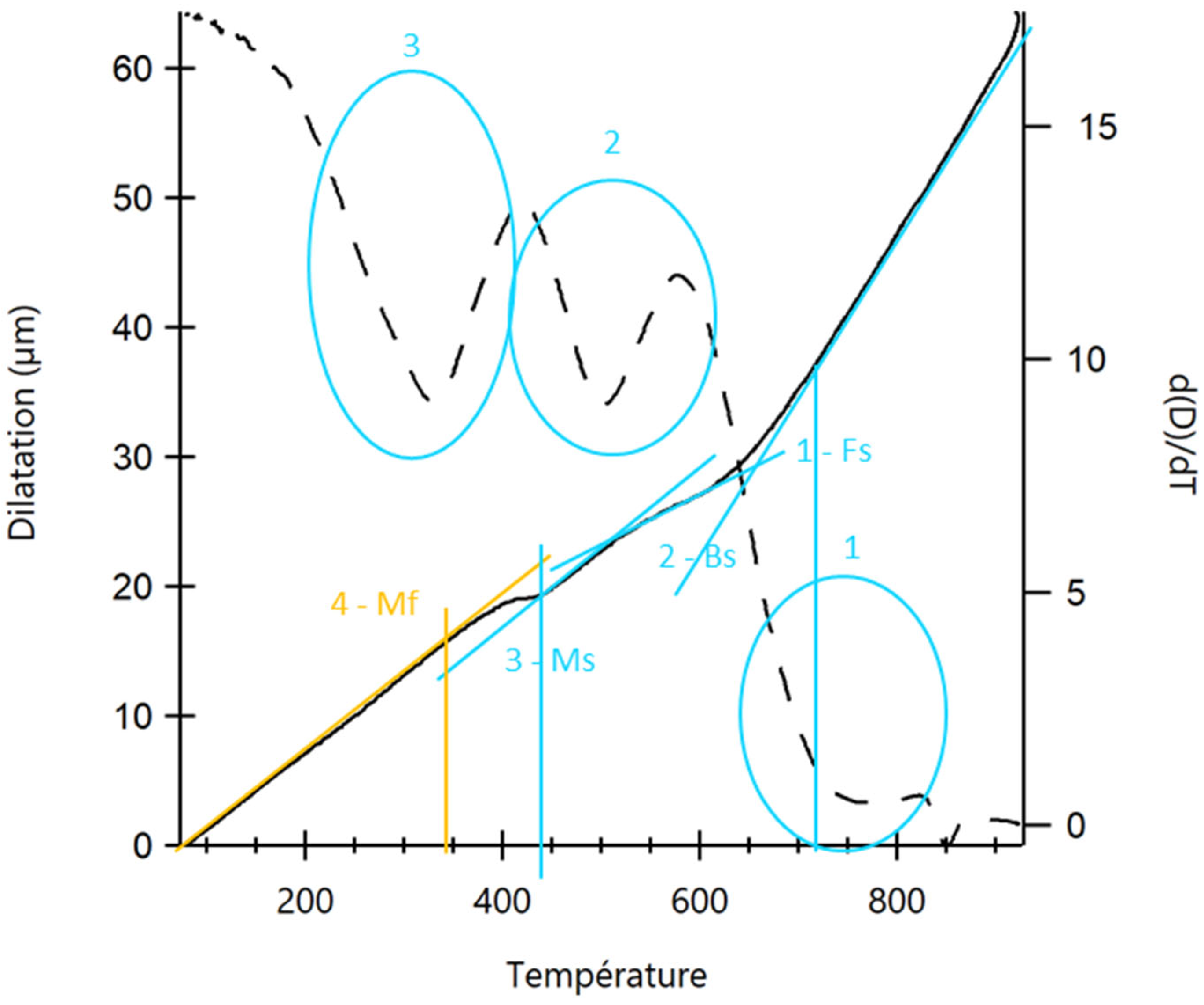
Plotting the derived dilatometry cooling curve (dD/dT = f(T), black dashed curve in Figure 2, derived from the D = f(T), black solid curve, where D is the sample expansion) allows one to depict the phase transformations occurring within the same temperature interval. Then, the start and end temperatures of the transformations were determined using the derived curve of the sample expansion and the tangent method (blue segments in Figure 2).
Prior to quenching, the samples were austenitized at 920 °C for 30 min. The microstructural analysis of the quenched samples after etching revealed the amount of the different phases and the corresponding start and end transformation temperatures. These values were then used to generate CCT diagrams of both steels at cooling rates between 0.1 and 250 °C.s−1. These diagrams were then compared with those generated using JMatPro® software v13, which is widely used in the industry, taking into account the chemical composition, mechanical properties, grain size, and austenitization temperature.
Finally, a carbonitriding treatment was carried out on fine-blanked samples, using an industrial carbonitriding conveyor furnace. This treatment was performed according to the parameters determined by the CCT diagrams, in order to reproduce the in-service heat treatment condition applied to the industrial parts. Then, the microstructure of these samples was studied to analyze the effect of the carbonitriding treatment on the part dimensions.

3. Results and Discussion

3.1. Mechanical Properties and Fine Blanking Behavior

Table 2 presents the main mechanical parameters of both steels in their initial state, obtained from tensile tests performed at a strain rate of 10−3 s−1. Compared to C18E steel, 22MnB5 exhibits higher mechanical resistance and similar ductility, considering the natural dispersion of fracture elongation. Both steels exhibit ductile behavior, with an ultimate deformation of up to 30%, which is suitable for the forming process.
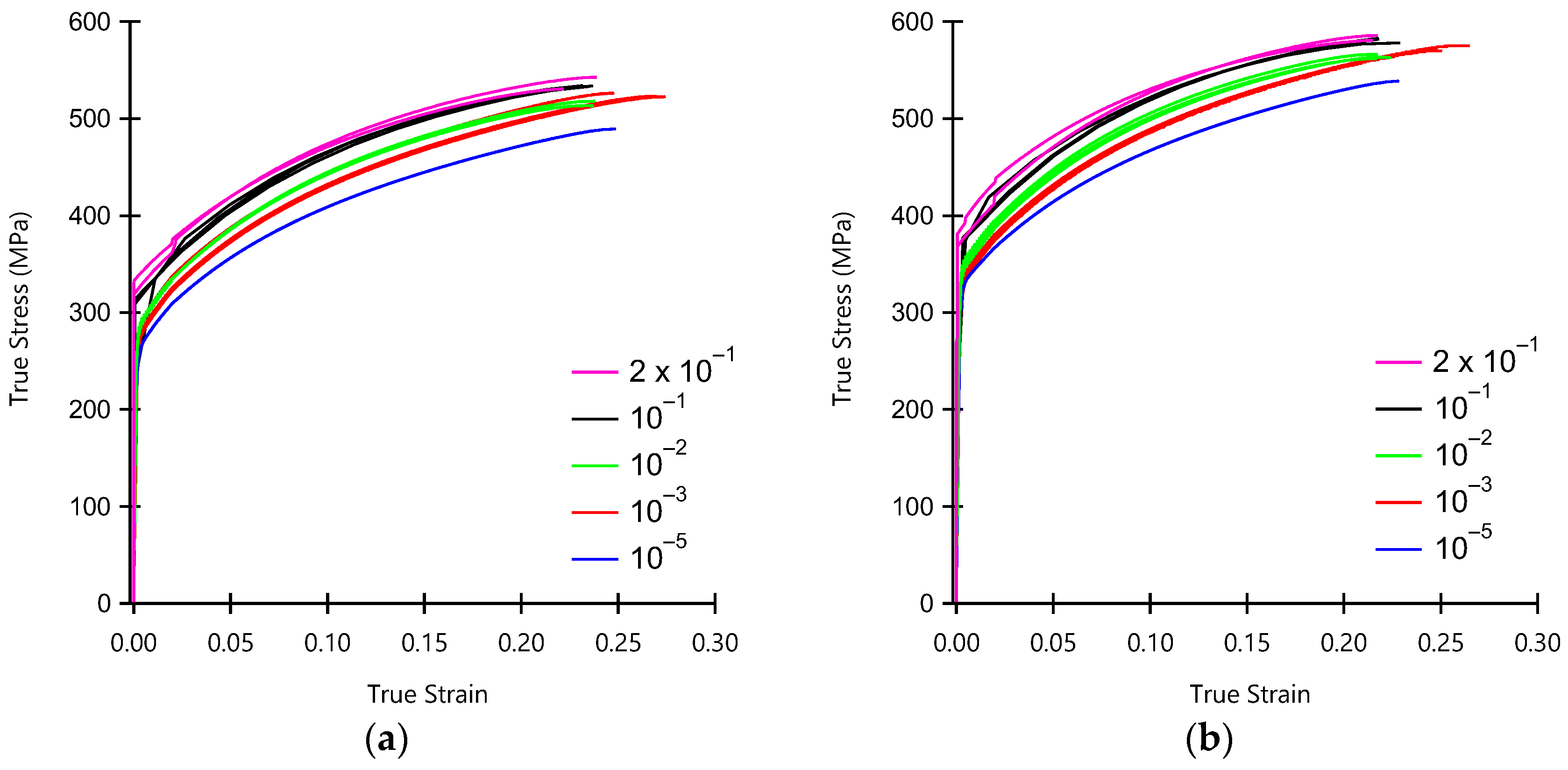
Considering the typical strain rates used in the industrial fine blanking process (about 10 s−1), and the maximum value available in tensile test conditions (typically 10−1 s−1), the sensitivity of the steels to the strain rate could be an issue. Figure 3 shows the tensile curves of both steels as a function of the strain rate. A logarithmic increase in σe and σm with strain rate has been observed, up to a saturation point at the highest strain rates.
The Fields–Backofen [27] law is commonly used to predict the sensitivity of metals to the strain rate:
σ t = K   ε t n   ε ˙ m
where σt is the true stress, εt is the true strain, K and n are the coefficients related to the Hollomon hardening law, and ε ˙ is the strain rate and m is the strain sensitivity coefficient. If m is close to 0, the mechanical properties of the material are invariant to the strain rate. The hardening coefficient, n, is independent of the strain rate in both steels (n = 0.18 ± 0.02). m was evaluated for several deformation values, and the values found were almost constant and similar for both steels (m = 0.015 ± 0.005). Consequently, the strain rate has no significant effect on the mechanical properties within the range of tensile experiments. This behavior is consistent with what is typically reported for ferritic steels in the literature. Therefore, we can assume that, even at higher speeds (10 s−1), representative of the fine blanking process, the results of tests carried out on the tensile machine correctly represent those carried out at the industrial level.
Figure 4a shows the load–displacement curves obtained during fine blanking with the developed tool for three C18E samples, with a half-cutting height of 2.5 mm, a negative clearance of 0.1 mm, and a strain rate of 2.10−1 s−1. High reproducibility and weak experimental dispersion were evidenced, as supported by measurements of the final external and internal diameters of the formed samples, which differ by no more than 0.01 mm (see inset in Figure 4a). Figure 4b shows the load–displacement curves obtained during fine blanking of three C18E and 22MnB5 samples with a half-cutting height of 3.2 mm, and different clearances. As expected, given the tensile mechanical properties in Table 2, the necessary load for fine blanking is higher for 22MnB5, indicating better forming behavior by the half-cutting process for C18E. Furthermore, the maximum force increases as the negative clearance increases (i.e., as the matrix diameter decreases), since more material must be removed during forming at higher clearance values.

3.2. Microstructural Analysis

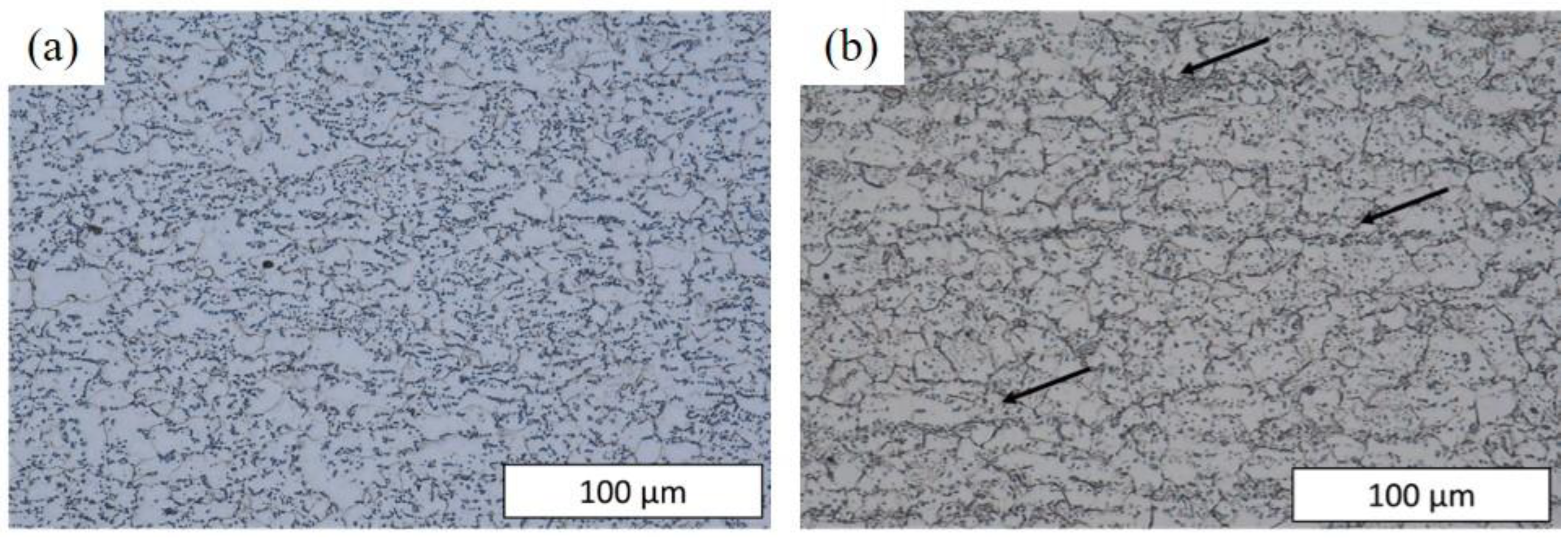
Microstructural observations were carried out on the alloys in their initial state and after fine blanking. The initial microstructure of both steels consists of ferrite and globular cementite carbides (Figure 5), which is ideal for forming parts by fine blanking [28]. Figure 5b shows that some carbide bands are present in the mid sheet thickness of 22MnB5 (underlined by arrows), though few are detectable in C18E (Figure 5a). These segregation bands are generally considered a preferential pathway for fracture propagation [29,30].
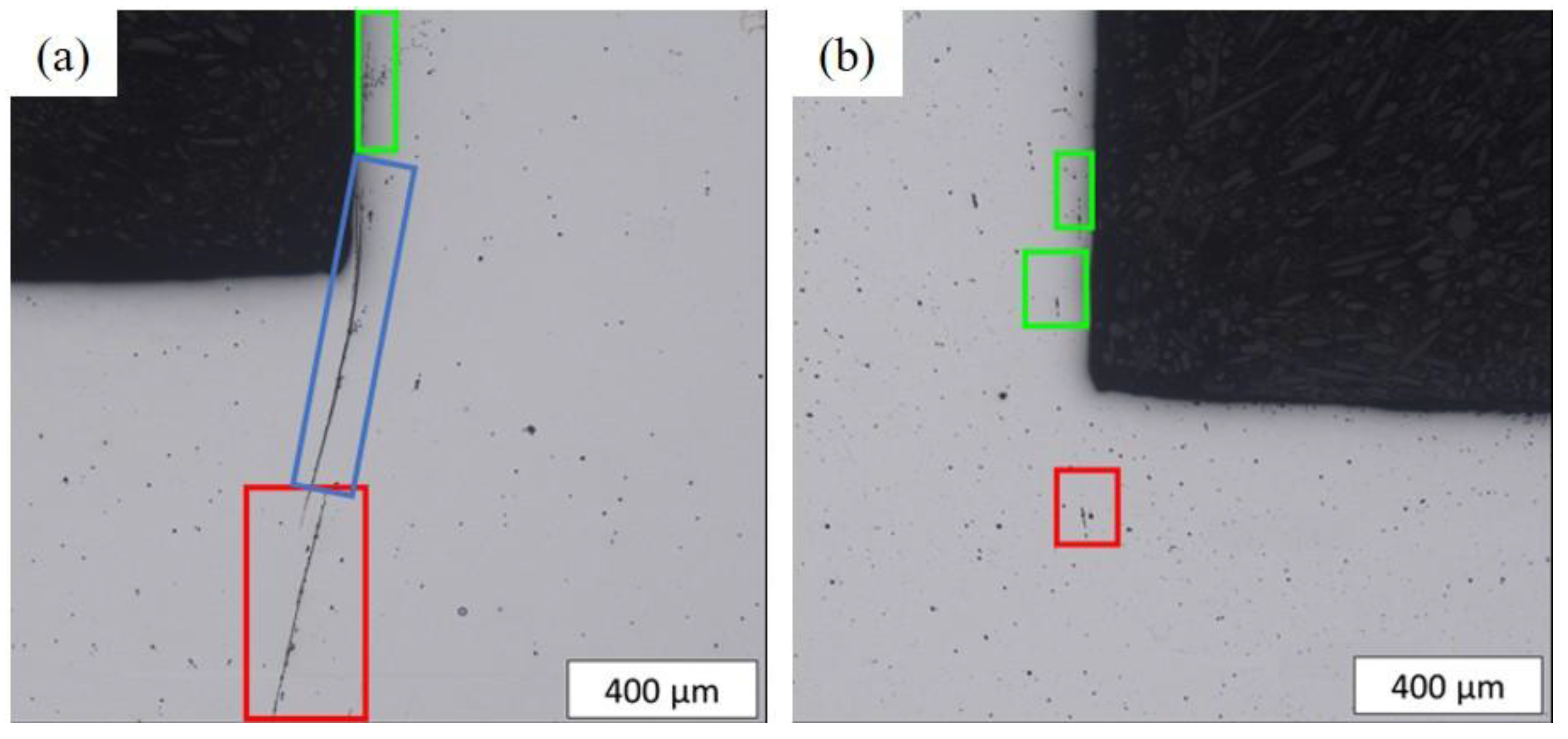
Numerous cracks were observed in C18E after fine blanking at half-cutting heights of 2.5 and 3.2 mm, and die diameters of 9.8 and 9.9 mm (i.e., negative clearances of 0.2 and 0.1 mm, respectively; see Figure 6a). Three types of cracks were observed: internal cracks in the core of the shear area (red boxes in Figure 6), surface cracks (green boxes), and edging cracks (blue box) on the die side of the specimen. Small cracks were only detected in 22MnB5 samples made with the extreme blanking configuration (i.e., a half-cutting height of 3.2 mm and a die diameter of 9.9 mm).
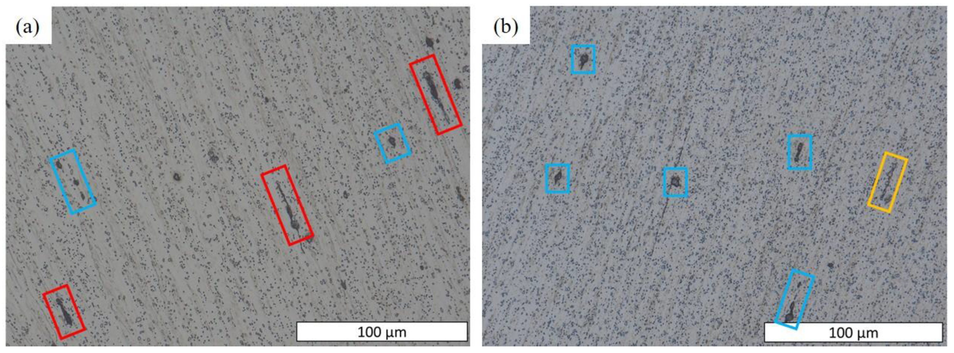
The cracks observed in the C18E samples, which were formed using extreme parameters (i.e., die diameters of 9.8 and 9.9 mm and half-cutting heights of 2.5 and 3.2 mm), generally originate from non-metallic inclusions (see the red boxes in Figure 7a). Inclusions without nearby cracks can also be observed in the same zone (blue boxes in Figure 7a). A few inclusions without nearby cracks have also been detected in the 22MnB5 specimens (Figure 7b).
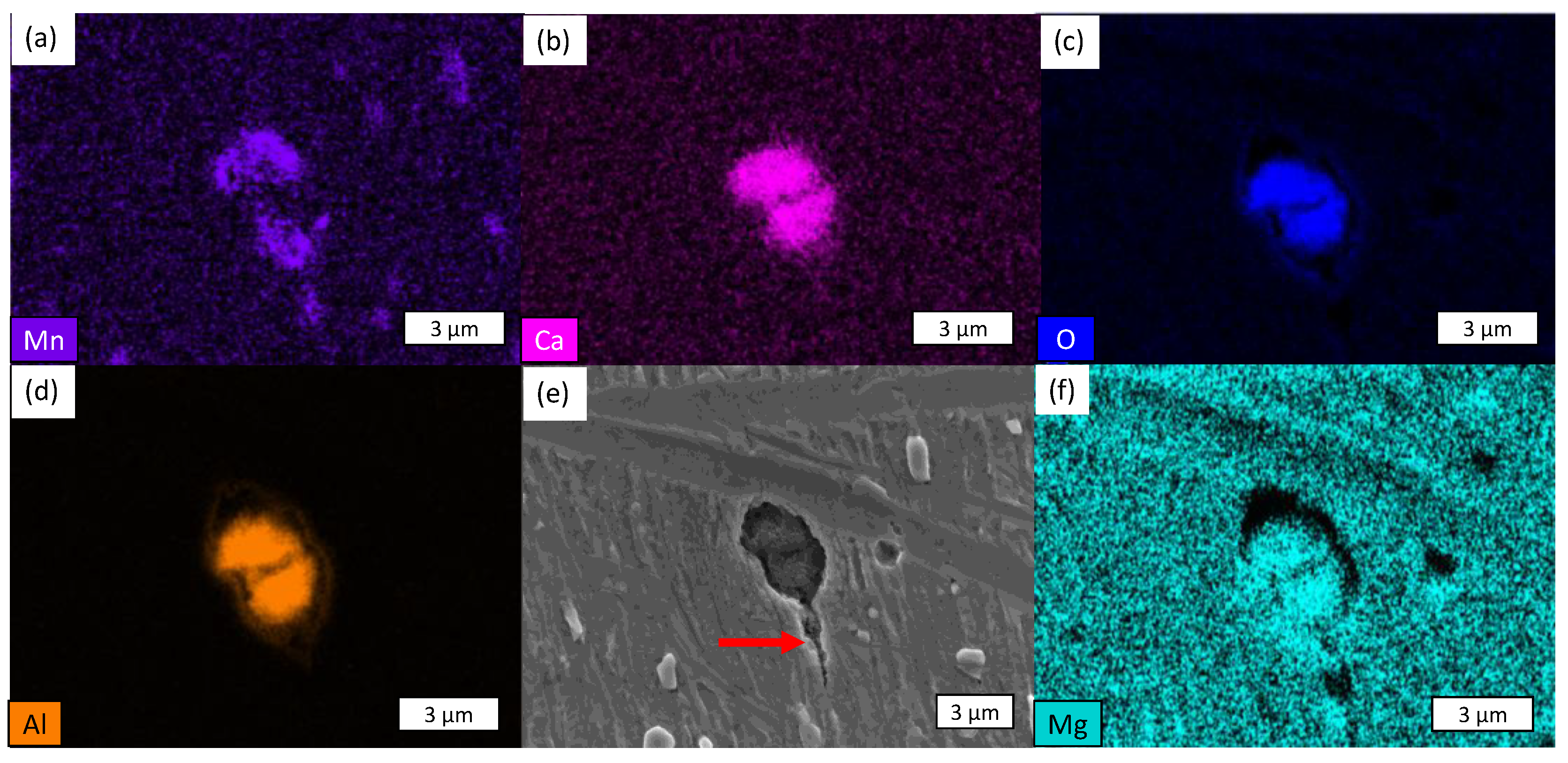
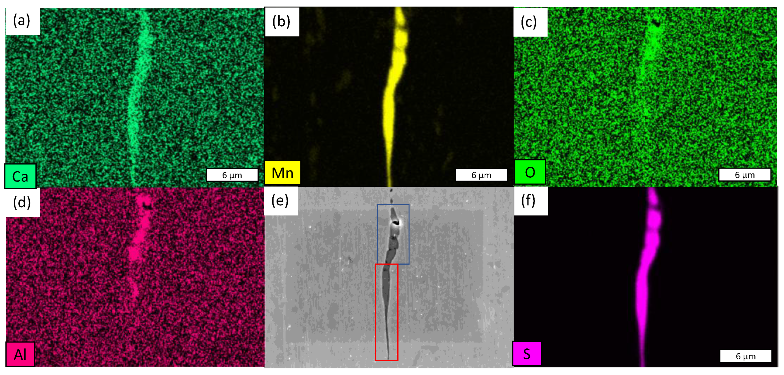
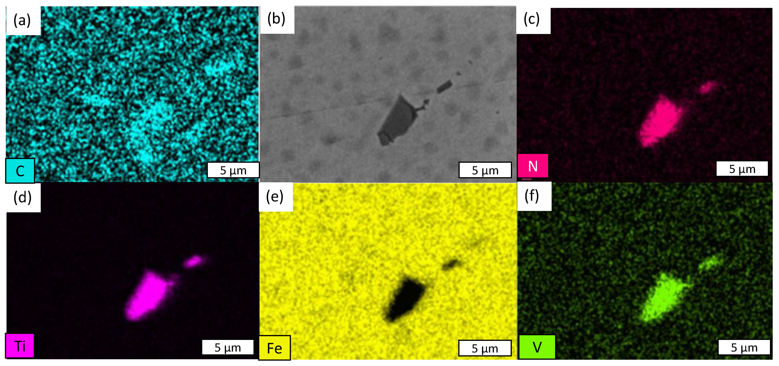
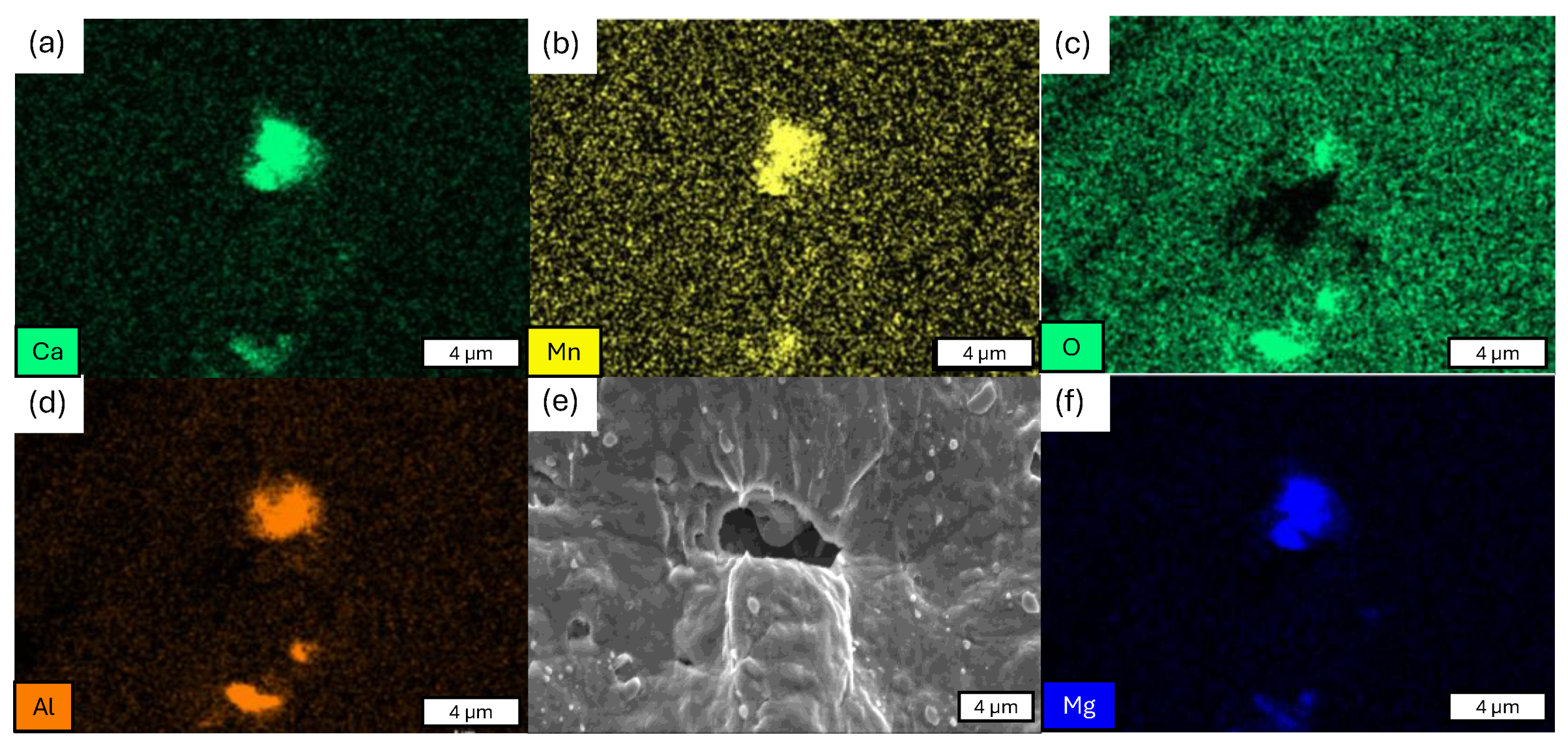
To identify the nature of the observed inclusions, EDS mapping analyses were performed in areas rich in inclusions, particularly in the shear zone of the blanked samples (Figure 8 and Figure 9). Although EDS cannot reliably quantify light elements such as nitrogen and oxygen, determining their presence or absence may provide insight into the chemical nature of the inclusions.
Different types of inclusions were identified. Figure 8, for instance, shows an aluminum-, calcium-, and magnesium-rich inclusion, found in a blanked C18E sample. Approximate quantification of the weight percentages of the detected elements suggests that the chemical formula of this inclusion is Al2O3-(Ca, Mg)O. Such inclusions are often observed near crack initiation points, as indicated by the red arrow in Figure 8e. These inclusions are exogenous inclusions, originally present in the steels due to the removal of refractory particles during the steelmaking process, and solidifying at around 1600 °C.
Figure 9 shows a manganese sulfide (MnS) inclusion (marked by the red box) found in a blanked C18E sample. This inclusion is easily identifiable due to its elongated shape along the rolling direction of the steel sheets. MnS inclusions are sometimes associated with another type of inclusion, a mixed inclusion consisting of a calcium or alumino-calcium core surrounded by an MnS shell. This type of inclusion is shown in the blue box in Figure 9.
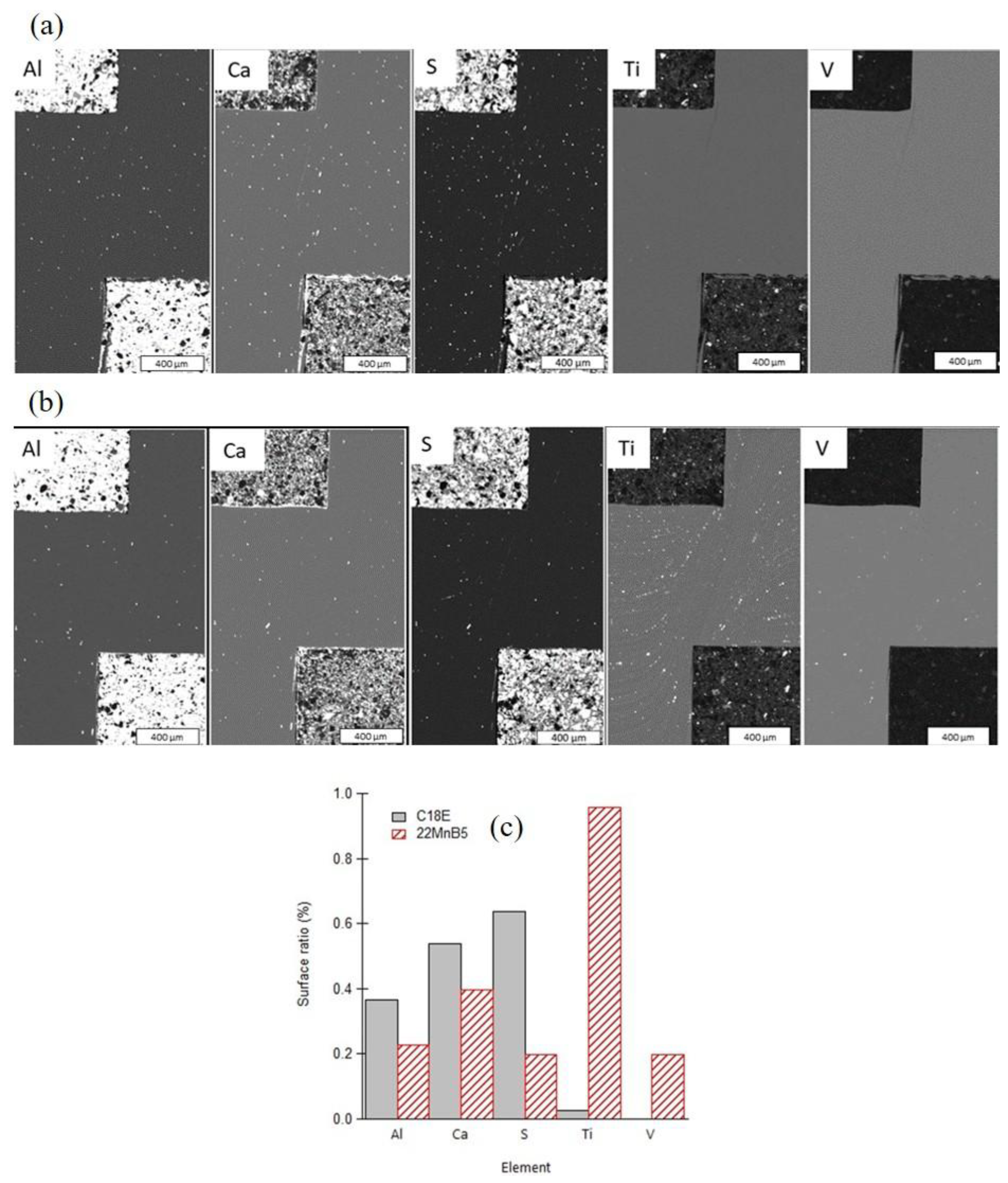
The formation of inclusions depends on the presence of residual and additional elements in steels. Electron microprobe analyses were performed to study the distribution of these chemical elements within fine-blanked samples. Figure 10 shows the distribution and the macroscopic concentration of aluminum and calcium, which are likely to form oxide inclusions; sulfur, which forms manganese sulfide inclusions; and titanium and vanadium, which produce nitride inclusions. According to the microprobe analysis, the presence of a chemical element is indicated by white dots on the produced map. The intensity of the dots increases as the amount of the corresponding element increases. Figure 10c shows the estimated concentration of each element, derived from the surface area of white dots calculated from the microprobe analysis maps.
The concentration and distribution of the studied elements appear to differ according to the type of steel. The elements Al, Ca, and S are present in high concentrations in the shear region of the C18E samples. These elements are also present in the 22MnB5 samples, but in smaller amounts, due to their higher purity compared to C18E. Consequently, calcium and alumino-calcium inclusions are present in both steels. Additionally, C18E has a higher sulfur content than 22MnB5 in the shear zone, resulting in the presence of sulfur and mixed inclusions in C18E samples.
Conversely, titanium and vanadium are more prevalent in 22MnB5 steel than in C18E steel. These elements may lead to the formation of nitride inclusions, which have been identified in the shear areas of 22MnB5 samples, as shown in Figure 11.
The presence of inclusions leads to stress concentration, which can result in cracks during steel forming. The identified inclusions exhibit either brittle or ductile mechanical behavior, depending on their chemical composition. Brittle behavior is exhibited by oxide inclusions, which create cavities on both sides along the deformation direction. These cavities act as nucleation sites for cracking. Manganese sulfide inclusions are known to exhibit ductile behavior. They deform easily along the forming direction, without nucleating voids at the interfaces. The difference in deformation behavior observed in mixed inclusions, including brittle alumino-calcite and ductile MnS inclusions, results in the formation of cavities, as seen in C18E samples (Figure 12). During deformation, cracks initiate from these cavities and easily propagate along the deformed manganese sulfide, reducing the steel’s formability.
Finally, nitride inclusions are extremely brittle and do not deform during steel forming. Rather, they break without generating a cavity or a microcrack. In conclusion, alumino-calcite inclusions, which are abundant in the studied C18E steel, are found to be the main cause of internal cracking nucleation. Elongated manganese sulfides, on the other hand, promote crack propagation.
In 22MnB5 steel, cracks mostly originate from a few alumino-calcite inclusions. Only a few aluminum-calcium and MnS inclusions were observed in this steel, which limits internal cracking during forming. 22MnB5 also contains a large amount of titanium nitrides; however, these inclusions do not impact cracking behavior.

3.3. Impact of a Carbonitriding Heat Treatment on the Fracture Resistance During Fine Blanking

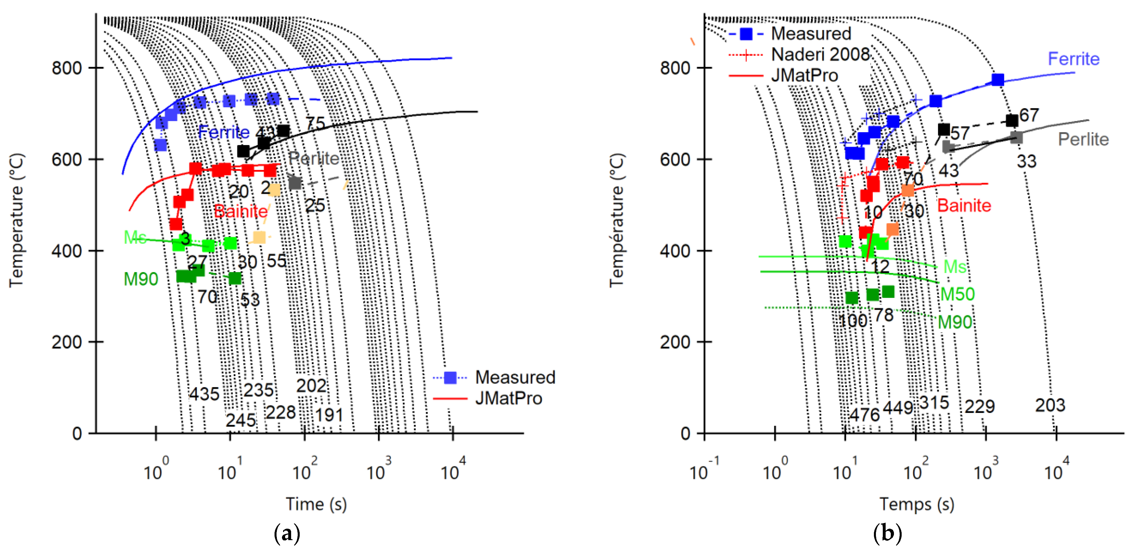
In industry, CCT diagrams are used to determine the optimal cooling rate during the carbonitriding heat treatment of fine-blanked parts, which is necessary to form the desired martensitic structure for surface hardening. Figure 13 shows the CCT diagrams of C18E and 22MnB5, created using experiments performed with a Gleeble thermo-mechanical simulator. These diagrams illustrate the crystalline phases that develop in a material as it cools at various rates. The starting and ending phase transformation temperatures are plotted as a function of transformation time for different cooling rates, represented by dotted curves on the diagram. Additionally, the proportion (in wt.%) of each phase at the boundary of its stability domain, and the hardness achieved at room temperature (at the bottom of the diagram), are given for different typical cooling rates.
Naderi [24] proposed a CCT diagram for a steel with a composition similar to that of 22MnB5 considered in this work. This diagram aligns well with our experimental results (see the cross markers in Figure 13b) and agrees with the simulated data obtained using the JMatPro® software (continuous lines in Figure 13). However, the bainite and pearlite transformations occur at higher cooling rates in our specimens. This behavior could be explained by the slight difference in the chemical composition of the two steels, particularly the higher amount of manganese in our samples.
According to CCT diagrams, 22MnB5 has a higher hardenability than C18E. The CCT diagram of C18E shifts toward shorter transformation times compared to 22MnB5, meaning that higher cooling rates are required to produce out-of-equilibrium phases in this steel. 22MnB5 samples exhibit a full martensitic structure at a cooling rate of 25 °C/s, while C18E samples have a mixed microstructure of martensite, bainite, and ferrite. Even at a cooling rate of around 250 °C/s, a full martensitic microstructure is never reached in C18E samples. This result is due to the different chemical compositions of the two steels. For instance, carbon, manganese, and boron are known to increase the hardenability of steels [26]. Conversely, some residual elements, such as phosphorus, sulfur, and aluminum, are reported in the literature to reduce hardenability [31]. Although some residual elements in 22MnB5, such as phosphorus and aluminum, reduce hardness, the presence of elements that promote hardness (chromium, manganese, and boron, and a higher carbon content than in C18E) ultimately increases hardenability. In contrast, C18E has residual elements that only reduce final hardenability.
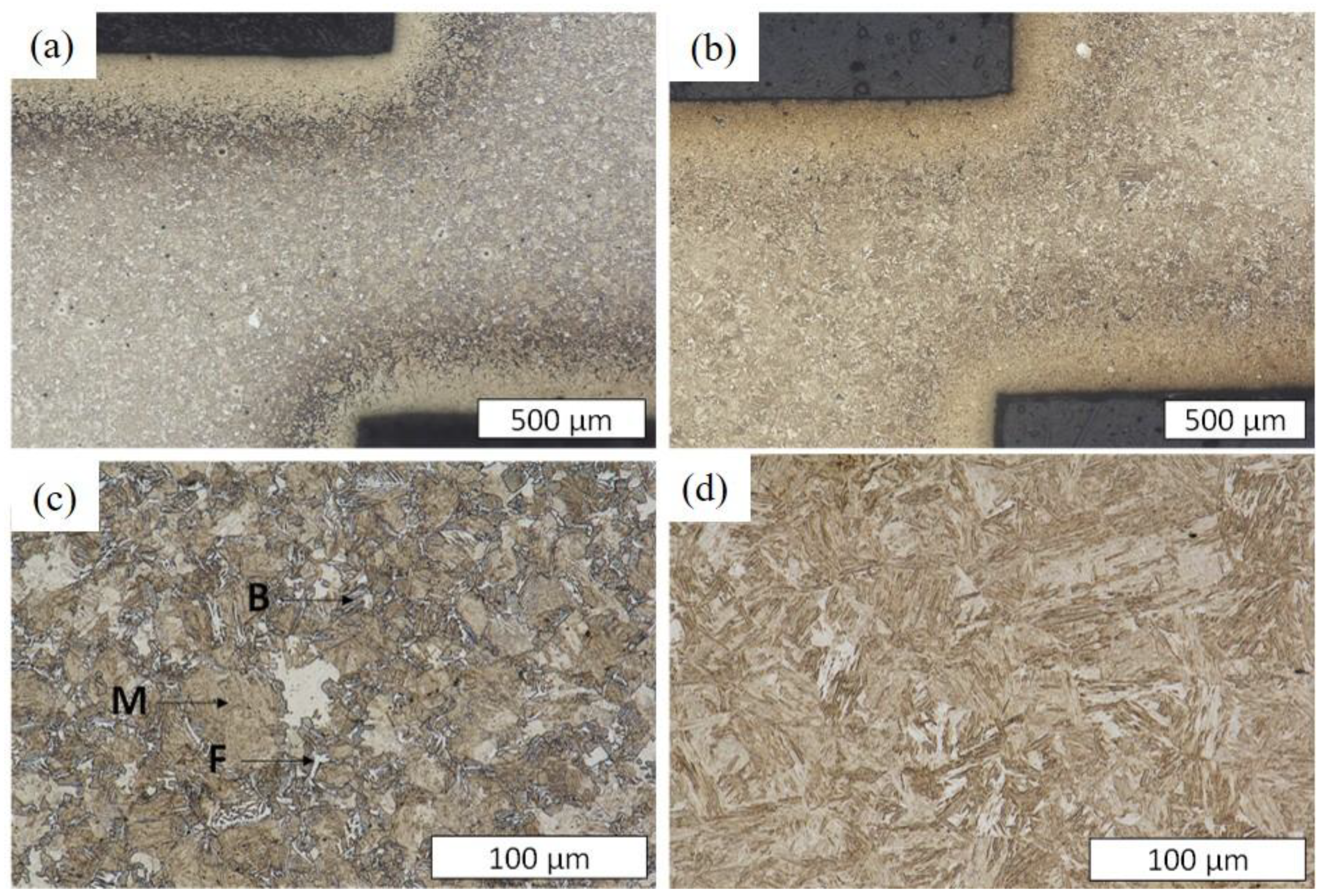
According to the CCT diagrams represented in Figure 13, fine-blanked specimens were carbonitrided. This process included a heat treatment with a complete austenitic transformation of the microstructure, followed by an oil quench, in order to form the martensitic phase. The cooling rates applied to the C18E and 22MnB5 samples were set to the maximum values, leading to martensite formation. The 22MnB5 samples exhibited a fully martensitic structure, consistent with the CCT diagrams (Figure 14b,d). In contrast, the C18E samples revealed a mixed microstructure composed of martensite, bainite, and ferrite (Figure 14a,c). This mixed microstructure causes unexpected dimensional variations in the blanked samples. Measurements of the external and internal diameters taken from transverse cuts of C18E-treated samples reveal significant differences compared to the dimensions measured before heat treatment, with variations of up to +0.2 mm. Such samples would be considered non-conforming in an industrial process. Conversely, 22MnB5 samples with a fully martensitic structure show smaller dimensional differences before and after heat treatment, with variations of less than + 0.15 mm, as well as a smaller dispersion of the measured values. These differences are consistent with industrial specifications.
Finally, regardless of the blanking configuration, no cracks were detected within the shearing area of either steel after carbonitriding. This self-healing property can be attributed to the phase transformations and related dimensional variations that occur during heat treatment.

4. Conclusions

We investigated the fine blanking process of C18E and 22MnB5 steels using an original characterization tool designed for a tensile testing machine. This tool produced simple geometries with various clearance and half-cutting height values. The cracking mechanisms in the shear areas were analyzed, as was the impact of carbonitriding after heat treatment on the final hardenability. The main results of this study are summarized below:
  • Numerous cracks were observed in C18E at a medium half-cutting height, while only a few crack initiations were detected in 22MnB5 at a higher half-cutting height.
  • The presence of cracks in the shear areas is correlated with the different types of inclusions present in the two steels. Cracks originate from cavities caused by brittle alumino-calcite inclusions. Manganese sulfide inclusions promote the propagation of previously formed cracks by delaminating from the metallic matrix. These inclusions are more prevalent in the considered C18E than in 22MnB5, resulting in greater cracking after blanking.
  • Compared to the C18E steel, 22MnB5 exhibits better hardenability with carbonitriding thermal treatment. This treatment creates the martensite structure necessary to meet the surface hardness requirements of parts used in the automotive industry. A quench rate of 25 °C/s is sufficient for the formation of martensite in 22MnB5. However, C18E never obtains a full martensitic structure, even with quench rates as high as 250 °C/s, leading to dimensional instability of parts.
Finally, the 22MnB5 steel exhibits better formability than C18E according to the fine blanking process. This is due to the high chemical purity of 22MnB5 and its low inclusion levels, which promote crack initiation within the C18E samples. Additionally, the good hardenability of 22MnB5 enables a fully martensitic microstructure to be obtained after carbonitriding thermal treatment, using lower cooling rates than those used for the C18E steel.

Author Contributions

Conceptualization, E.H., M.M. and A.A.; Methodology, E.H., M.M. and A.A.; Software, M.M. and A.A.; Validation, T.C., E.H., M.M. and A.A.; Formal Analysis, T.C., E.H. and S.E.; Investigation, T.C., E.H. and S.E.; Resources, E.H., M.M. and A.A.; Data Curation, T.C. and S.E.; Writing—Original Draft Preparation, T.C. and S.E.; Writing—Review and Editing, E.H., S.E., M.M.; Visualization, T.C., E.H. and S.E.; Supervision, E.H., M.M. and A.A.; Project Administration, E.H., M.M. and A.A.; Funding Acquisition, E.H., M.M. and A.A. All authors have read and agreed to the published version of the manuscript.

Funding

This work was supported by the Forvia R&D Center in Caligny, France.

Data Availability Statement

The original contributions presented in this study are included in the article. Further inquiries can be directed to the corresponding author.

Acknowledgments

Special thanks go to Valérie Woimbée, David Even, and Claude Colasse for their valuable contributions. Thanks also to Cendrine Folton and Xavier Larose for their support with the experiments, metallographic analysis, and microscopic observations.

Conflicts of Interest

Authors Thomas Chiavazza, Margaux Marnier and Aurélie Achille were employed by the company Forvia Seating. The remaining authors declare that the research was conducted in the absence of any commercial or financial relationships that could be construed as a potential conflict of interest.

Abbreviations

The following abbreviations are used in this manuscript:
CCTContinuous Cooling Transformation
GDOESGlow Discharge Optical Emission Spectroscopy
SEMScanning Electron Microscopy
EDSEnergy Dispersive Spectroscopy

References

  1. Zheng, Q.; Zhuang, X.; Zhao, Z. State-of-the-art and future challenge in fine-blanking technology. Prod. Eng. 2019, 13, 61–70. [Google Scholar] [CrossRef]
  2. Quazi, P.; Shaikh, R. An overview of clearance optimization in sheet metal blanking process. Int. J. Mod. Eng. Res. 2012, 2, 4547–4558. [Google Scholar]
  3. Fan, W.; Li, J. An investigation on the damage of AISI-1045 and AISI-1025 steels in fine-blanking with negative clearance. Mater. Sci. Eng. A 2009, 499, 8–251. [Google Scholar] [CrossRef]
  4. Hartmann, C.; Weiss, H.; Lechner, P.; Volk, W.; Neumayer, S.; Fitschen, J.; Steidl, G. Measurement of strain, strain rate and crack evolution in shear cutting. J. Mater. Process Technol. 2021, 288, 116872. [Google Scholar] [CrossRef]
  5. Aoki, I.; Takahashi, T. Material flow analysis on shearing process by applying Fourier phase correlation method-analysis of piercing and fine-blanking. J. Mater. Process Technol. 1996, 134, 45–52. [Google Scholar] [CrossRef]
  6. Da Costa, E.; Silva, A. The effects of nonmetallic inclusions on properties relevant to the performance of steel in structural and mechanical applications. J. Mater. Res. Technol. 2019, 8, 2408–2422. [Google Scholar] [CrossRef]
  7. Kobayashi, H.; Kurokawa, T.; Shimomura, T.; Matsudo, K.; Miyahara, S. Effect of non-metallic inclusion of flange cracking of drawn and ironed can from tinplate. Trans. Iron Steel Inst. Jpn. 1983, 23, 410–416. [Google Scholar] [CrossRef]
  8. Wang, C.; Liu, X.-G.; Gui, J.-T.; Du, Z.-L.; Xu, Z.-F.; Guo, B.-F. Effect of MnS inclusions on plastic deformation and fracture behavior of the steel matrix at high temperature. Vacuum 2020, 174, 109209. [Google Scholar] [CrossRef]
  9. Wang, Y. Effects of MnS inclusions on mechanical behavior and damage mechanism of free-cutting steel: A molecular dynamics study. J. Mol. Graph. Model. 2023, 118, 108354. [Google Scholar] [CrossRef] [PubMed]
  10. Pokorny, A.; Pokorny, J. Inclusions non métalliques dans l’acier. Technol. L’ingénieur 1998, 2, 1–36. [Google Scholar] [CrossRef]
  11. Muan, A.; Osborn, E. Phase Equilibria Among Oxides in Steelmaking; Addison-Wesley Publishing Company: Boston, MA, USA; Reading, MA, USA, 1965. [Google Scholar]
  12. Kiessling, R.; Lange, N. Non-metallic inclusions in steels. Lond. Met. Soc. 1978, 2, 190–194. [Google Scholar]
  13. Shiraiwa, T.; Fujino, N.; Matsuno, F. Properties of non metallic inclusions in steels. Sumitomo Search 1974, 11, 85–100. [Google Scholar]
  14. Yu, H.-L.; Bi, H.-Y.; Liu, X.-H.; Tu, Y.-F. Strain distribution of strips with spherical inclusion during cold rolling. Trans. Nonferrous Met. Soc. China 2008, 18, 919–924. [Google Scholar] [CrossRef]
  15. Yu, H.; Liu, X.; Bi, H.; Chen, L. Deformation behavior of inclusions in stainless Steel strips during multi-pass cold rolling. J. Mater. Process Technol. 2009, 209, 455–461. [Google Scholar] [CrossRef]
  16. Kaushik, P.; Lehmann, J.; Nadif, M. State of the art in control of inclusions, their characterization, and future requirements. Metall. Mater. Trans. B Process Metall. Mater. Process. Sci. 2012, 43, 710–725. [Google Scholar] [CrossRef]
  17. Ervasti, E.; Ståhlberg, U. Void initiation close to a macro-inclusion during single pass reductions in the hot rolling of steel slabs: A numerical study. J. Mater. Process Technol. 2005, 170, 142–150. [Google Scholar] [CrossRef]
  18. Wu, M.; Fang, W.; Chen, R.M.; Jiang, B.; Wang, H.B.; Liu, Y.Z.; Liang, H.L. Mechanical anisotropy and local ductility in transverse tensile deformation in hot rolled steels: The role of MnS inclusions. Mater. Sci. Eng. A 2019, 744, 324–334. [Google Scholar] [CrossRef]
  19. Ghosh, A.; Modak, P.; Dutta, R.; Chakrabarti, D. Effect of MnS inclusion and crystallographic texture on anisotropy in Charpy impact toughness of low carbon ferritic steel. Mater. Sci. Eng. A 2016, 654, 298–308. [Google Scholar] [CrossRef]
  20. Zhuang, X.; Ma, S.; Zhao, Z. A microstructure-based macro-micro multi-scale fine-blanking simulation of ferrite-cementite steels. Int. J. Mech. Sci. 2017, 128–129, 414–427. [Google Scholar] [CrossRef]
  21. Chen, H.; Zhao, L.; Lu, S.; Lin, Z.; Wen, T.; Chen, Z. Progress and perspective of ultra-high-strength martensitic steels for automobile. Metals 2022, 12, 2184. [Google Scholar] [CrossRef]
  22. Karolak, C.; Montmitonnet, P.; Moore Parks, D.; Delattre, G.; Bouchard, P.O. Analysis and modeling of the failure behavior of carbonitrided parts. Procedia Eng. 2017, 207, 2030–2035. [Google Scholar] [CrossRef]
  23. Krauss, G. Heat Treated Martensitic Advanced Manufacture Systems for Advanced Manufacture. ISIJ Int. 1995, 35, 349–359. [Google Scholar] [CrossRef]
  24. Naderi, M.; Saeed-Akbari, A.; Bleck, W. The effects of non-isothermal deformation on martensitic transformation in 22MnB5 steel. Mater. Sci. Eng. A 2008, 487, 445–455. [Google Scholar] [CrossRef]
  25. Bialobrzeska, B. Effect of alloying additives and microadditives on hardenability Increase Caused by Action of Boron. Metals 2021, 11, 589. [Google Scholar] [CrossRef]
  26. ISO 6892-1:2019; Metallic Materials—Tensile Testing Part 1: Method of Test at Room Temperature. ISO: Geneva, Switzerland, 2019.
  27. Fields, D.; Backofen, W. Determination of the strain hardening characteristics by torsion testing. Am. Soc. Test. Mater. Proceeding Sixtieth Annu. Meet. Soc. 1957, 57, 1259–1272. [Google Scholar]
  28. Lange, K.; Bizer, F.; Höfel, P.; Mukhoty, A.; Singer, H. Cold Forming and Fineblanking; Edelsthalwerke Buderus AG: Hessen, Germany; Feintool AG: Lyss, Switzerland; Lyss Hoesch Hohenlimburg GmbH: Hagen, Germany; Kallwalzwerk Brockhaus GmbH: Lüdenscheid, Germany, 1997. [Google Scholar]
  29. Tong, C.; Zhu, G.; Rong, Q.; Yardley, V.A.; Shi, Z.; Li, X.; Luo, J.; Lin, J. Investigation of austenitising behaviour of medium-Mn steel in the hot-stamping heating process. J. Mater. Process Technol. 2021, 297, 117269. [Google Scholar] [CrossRef]
  30. Qian, L.; Ji, W.; Sun, C.; Fang, G.; Lian, J. Prediction of edge fracture during hole-flanging of advanced high-strength steel considering blanking pre-damage. Eng. Fract. Mech. 2021, 248, 107721. [Google Scholar] [CrossRef]
  31. Llewellyn, D.; Marriott, J.; Naylor, D.; Thewlis, G. The effects of residual elements on the properties of engineering steels. Philos. Trans. R. Soc. London. Ser. A Math. Phys. Sci. 1980, 295, 69–85. [Google Scholar]
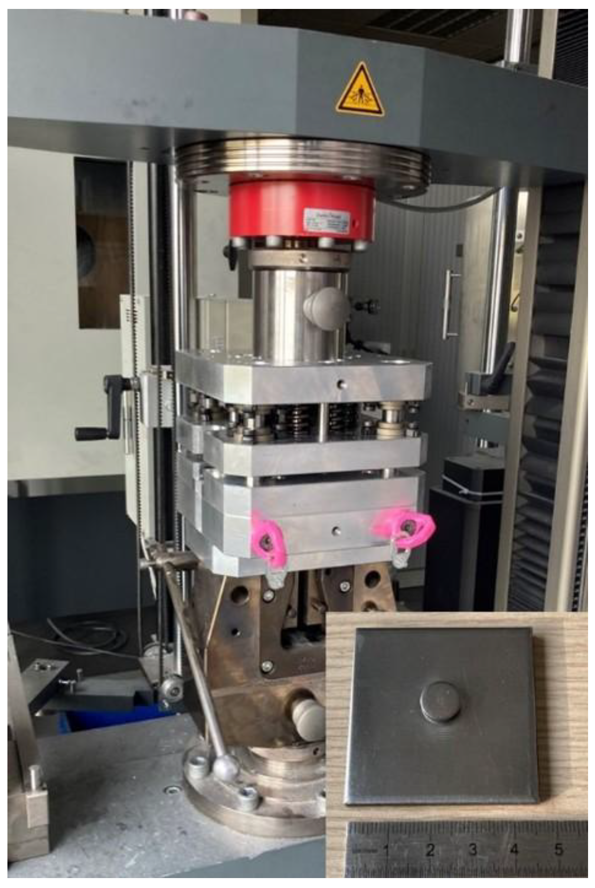
Figure 1. Tool used for the fine blanking tests performed on a tensile test machine. In the inset is shown an example of a fine-blanked specimen.
Metals 15 01173 g001
Figure 2. Example of dilatation vs. temperature curve and corresponding differentiated curve, allowing to obtain the start and end of ferritic (1 and 3), bainitic (2), and martensitic (4) transformations.
Metals 15 01173 g002
Figure 3. True tensile curves of (a) C18E and (b) 22MnB5 for different strain rates (in s−1).
Metals 15 01173 g003
Figure 4. Force applied to the tool versus punch displacement: (a) for a 2.5 mm half-cutting height and a die diameter of 9.9 mm for C18E; and (b) for a 3.2 mm half-cutting height and different clearance values, for C18E and 22MnB5.
Metals 15 01173 g004
Figure 5. Initial microstructure of (a) C18E and (b) 22MnB5. Ferrite appears in white and cementite in gray. Arrows point out the carbide segregation bands depicted in 22MnB5.
Metals 15 01173 g005
Figure 6. Micrographs of fine-blanked samples using a 0.1 mm negative clearance and a 3.2 mm half-cutting height. (a) C18E and (b) 22MnB5 steel. Internal cracks (red boxes), surface cracks (green boxes), and edging cracks (blue box) are observed in the shearing area.
Metals 15 01173 g006
Figure 7. Inclusions initiating cracks (red boxes) or without cracks nearby (blue boxes), within the shearing area of (a) C18E and (b) 22MnB5 (the yellow box highlights a nitride inclusion).
Metals 15 01173 g007
Figure 8. SEM micrograph (e) and EDS mapping (arbitrary colors) performed in the neighborhood of an Al2O3-(Ca, Mg)O inclusion in a C18E fine-blanked specimen: (a) manganese, (b) calcium, (c) oxygen, (d) aluminum, and (f) magnesium.
Metals 15 01173 g008
Figure 9. SEM micrograph (e) and EDS mapping (arbitrary colors) performed in the neighborhood of a manganese sulfide inclusion detected in a C18E fine-blanked specimen: (a) calcium, (b) manganese, (c) oxygen, (d) aluminum, and (f) sulfur (red box: MnS inclusion, blue box: calcium aluminate–manganese sulfide mixed inclusion).
Metals 15 01173 g009
Figure 10. Microprobe analysis maps showing the repartition of aluminum, calcium, sulfur, titanium, and vanadium, in the shear area of (a) C18E and (b) 22MnB5 fine-blanked samples; (c) estimation for both steels of the concentration of aluminum, calcium, sulfur, titanium, and vanadium per surface unit.
Metals 15 01173 g010
Figure 11. SEM micrograph (b) and EDS mappings (arbitrary colors) performed in the neighborhood of a titanium nitride inclusion in a 22MnB5 fine-blanked specimen: (a) carbon, (c) nitrogen, (d) titanium, (e) iron, and (f) vanadium.
Metals 15 01173 g011
Figure 12. SEM micrograph (e) and EDS mapping (arbitrary colors) performed in the neighborhood of an alumino-calcite inclusion surrounded by a manganese sulfide, detected in a C18E specimen: (a) calcium, (b) manganese, (c) oxygen, (d) aluminum, and (f) sulfur.
Metals 15 01173 g012
Figure 13. CCT diagrams created using experiments performed with the Gleeble 3500 thermo-simulator for (a) C18E and (b) 22MnB5 steels. A comparison is made with results obtained using JMatPro® software, Reprinted from Ref. [24].
Metals 15 01173 g013
Figure 14. Microstructure of carbonitrided C18E and 22MnB5 samples, fine-blanked according to a 0.3 mm negative clearance and a 2.5 mm half-cutting height. Global view of the shearing area of (a) C18E and (b) 22MnB5. Microstructure in the core of (c) C18E, showing a martensite (M)–bainite (B)–ferrite (F) microstructure, and (d) 22MnB5, showing a fully martensitic microstructure.
Metals 15 01173 g014
Table 1. Chemical composition of steels obtained by GDOES analysis (wt.%, Fe in balance).
CNCrMnSiPSMoCaAlTiBV
C18E0.1940.0120.0190.6670.1830.0100.0030.0060.0020.0090.0000.000Traces
22MnB50.224Traces0.1831.2350.2130.011Traces0.0060.0010.0360.0090.002Traces
Table 2. Mechanical properties in tension of C18E and 22MnB5 steels. σy: yield stress, σm: ultimate tensile stress, εf: fracture elongation (extracted from true stress–strain curves obtained with a strain rate of 10−3 s−1).
σy (MPa)σm (MPa)εf
C18E236 ± 2500 ± 60.31 ± 0.01
22MnB5286 ± 12549 ± 120.27 ± 0.03
Disclaimer/Publisher’s Note: The statements, opinions and data contained in all publications are solely those of the individual author(s) and contributor(s) and not of MDPI and/or the editor(s). MDPI and/or the editor(s) disclaim responsibility for any injury to people or property resulting from any ideas, methods, instructions or products referred to in the content.