Article

On the High Elastic Modulus Mechanism of Iron Matrix Composites

National Engineering Research Center for Advanced Rolling and Intelligent Manufacturing, University of Science and Technology Beijing, Beijing 100083, China
*
Author to whom correspondence should be addressed.
Metals 2025, 15(2), 129; https://doi.org/10.3390/met15020129
Submission received: 30 December 2024 / Revised: 23 January 2025 / Accepted: 25 January 2025 / Published: 27 January 2025
(This article belongs to the Special Issue Microstructure and Mechanical Behavior of High-Strength Steel)

Abstract

:
High modulus steels are characterized by high specific strength and specific stiffness, which can be attributed to the presence of hard reinforced particles. This paper investigates two common iron matrix composites, namely Fe/TiB2 and Fe/TiC, prepared through in situ reaction, focusing on their structures and properties. The results show that both types of reinforced particles in the high modulus steels consist of coarse primary particles and fine eutectic particles. In comparison to Fe/TiC composites, Fe/TiB2 composites exhibit larger elastic modulus (210 GPa). The reasons for the phenomenon that the experimentally measured values of the modulus of elasticity are lower than the calculated values at equilibrium are discussed. It was found that microporous defects left over from the casting process are often present inside the coarse primary particles, which can be the source of microcracks or fractures. In addition, matrix/particle interface stability calculations revealed that TiB2 possesses a distinctive hexagonal structure, resulting in a smaller interfacial distance (d0 = 1.375 Å) with the ferrite matrix phase. The high interfacial work of adhesion (Wad = 3.992 J/m2) further confirms the stronger interfacial stability of the Fe/TiB2 composite in comparison to the Fe/TiC composite.

1. Introduction

High modulus steel (HMS) is extensively utilized in wear and tear, aerospace, and energy-efficient transportation due to its high specific stiffness and specific yield strength [1,2]. Because of the hard reinforced particles in the matrix, HMS has a significantly greater elastic modulus than traditional high-strength steels. Borides, carbides, nitrides, and other similar particles are frequently used in HMS. TiB2 is regarded as the most promising reinforcing particle among them, due to its exceptional qualities, including high modulus (565 GPa), low density (4.52 g/cm3), high hardness (Hv = 35 GPa), and high thermodynamic stability [3]. In the Fe-Ti-B system, TiB2 can be synthesized in situ by eutectic reaction and thus expected to promote a homogeneous microstructure with low clustering and strong interfacial bonding. H. Springer et al. [4] investigated the effect of adding 5% content of a variety of alloying elements (Cr, Ni, Mo, etc.) on the Fe/TiB2 iron-matrix composites and found that Co and Cr can modify the particles, and the addition of Mn can adapt to the microstructure of the matrix. Shi et al. [5] added 10% of Ni into the Fe-TiB2 system and observed that the addition of Ni in the matrix suppressed the precipitation of blocky TiB2 particles, resulting in the growth of elongated particles resembling worms. Interestingly, this did not affect the elastic modulus of the composite material but instead improved the yield strength and elongation compared to the original material. Zheng et al. [6] designed a new “nano-treat” Fe-Ti-B high-modulus steel, which revisited the positive role of Fe2B and produced a Young’s modulus of 251 GPa, a specific stiffness of 34 GPa-cm3. TiC has a NaCl-type face-centered cubic structure with an elastic modulus of about 443 GPa and a hardness of about 30 GPa [7], while TiC/Fe composites are widely studied for their high hardness and wear resistance. Tu et al. [8] investigated the stability of heat treatment of composites containing 35% TiC. It was found that the new thermal cooling cycle (TCC) process not only improves the strength of the cemented carbide but also improves the dimensional stability of the TiC-reinforced particles. K. I. Parashivamurthy et al. [9] investigated the effect of Mn content variation on the organization and modulus of TiC hyper-eutectoid steels and found that the Young’s modulus of the composites reaches 296 GPa when the Mn reaches 5.48%. However, coarse, massive reinforced particles are inevitably generated during solidification, while high aspect ratio particles lead to particle–matrix interface debonding, which becomes the root of crack sprouting. Although there are many studies on TiB2/Fe and TiC/Fe composites, no systematic study has been carried out in the literature on the reinforced particles and their interfacial stability with the matrix with respect to the material elastic modulus of the composites.
Currently, studies on the interfacial stability between the reinforced particles and the substrate mainly analyze the lattice mismatch situation through the atomic scale [5,10,11,12,13], while the first principles is an atomic scale microanalytical method, which has been widely used in the field of material interfacial stability in recent years. Li et al. [14] studied the atomic structure, chemical bonding, stability, and fracture mechanism of the incoherent lattice TiB2 (0001)/Fe (111) interfaces terminated by B and Ti by utilizing first principles method and determined the atomic structure, chemical bonding, stability, and fracture mechanism of the interfaces terminated by B and Ti and semi-coherent lattice TiB2 (0001)/Fe (001) interfaces in terms of atomic structure, chemical bonding, stability, and fracture mechanisms, and the thermodynamically stable interfacial structure of semi-coherent lattice TiB2 (0001)/Fe (001) terminated with B has been determined. Yang et al. [15] have used a first principles density-functional plane-wave ultrasoft pseudopotential method to study the C- and Ti-terminated TiC (100)/Fe (100) interfacial atomic structure, bonding, cohesion energy, and interfacial energy and determined the thermodynamically stable interfacial structure of TiC (100)/Fe (100) terminated with C terminals.
In this paper, two typical modulus steels were prepared by in situ reaction, and their organization and properties were investigated. The morphological, fractional, and interfacial characteristics of the reinforced particle in the tested steels are analyzed. Theoretical prediction and experimental verification of HMS elastic modulus are carried out to explain the phenomenon that the experimental value of elastic modulus is lower than the predicted value, pointing out the unfavorable influence of defects in the in situ smelting process on the properties of composites, which is of guiding significance for the preparation process of modulus steel.

2. Materials and Experimental Methods

Two types of particle-reinforced iron matrix composites, Fe/TiB2 and Fe/TiC, were prepared by in situ reaction using Fe, Ti, Mn, high-purity BFe, and Cr as raw materials, and their compositions (mass percent, %) are shown in Table 1.
Alloy melting was carried out using a vacuum melting furnace. Fe, Mn, high-purity B, Fe alloy, and Cr were put into an alumina crucible, vacuumed to 0.1 Pa and then filled with argon gas to 10,000 Pa, and the crucible was heated to 1600 °C. After the metal material melted for 5 min, Ti material was added into the melt, and after continuing to melt at 1600 °C for 2 min, the metal liquid was poured into an iron mold preheated to 400 °C to obtain 150 × 100 × 10 (mm3) rectangular ingots.
The iron matrix composites were machined into specimens with specifications of ASTM E8 [16], φ8 × 40 mm, and 50 × 10 × 1.5 (mm3) using an EDM cutting machine for tensile mechanical property testing, compressive mechanical property testing, and elastic modulus testing, respectively. The mechanical properties (strength, plasticity, and elastic modulus) of the composites were tested using SANS CMT5105 electronic universal testing machine (CMT 5105, SANS, Shenzhen, China) at room temperature. The elastic modulus of the composites was tested using the resonance method. Metallographic specimens of size 10 × 5 × 2 (mm3) were cut at 1/4 of the ingot using a wire cutter, and after inlaying with the hot inlay method, the specimens were ground and polished to a mirror-like surface using 400~2000# sandpaper and 0.5~3 μm diamond polishing paste. Microstructure observation was carried out by using a LEXT OLS4100 laser confocal microscope (LEXT OLS4100, OLYMPUS, Tokyo, Japan).
The first principles calculation software Materials studio 2020 is used to construct the model, and all the calculations are done using the CASTEP package module for quantum mechanics based on density flood theory, and the ultrasoft pseudopotential is chosen as the potential function to describe the interactions between ions. The generalized gradient approximation (GGA) of the Perdew–Burke–Emzerhof (PBE) function is used to deal with the exchange correlation energy. The plane wave truncation energies after convergence test are all 350 eV, the Brillouin zone k-points are selected by the Monkhorst-Pack method, the grid of the speaking k-points is set to 10 × 10 × 8, and the geometry is optimized by the Broyden Fletcher Goldfarb Shanno (BFGS) algorithm. During the self-consistent calculations, the energy converges with an accuracy of 1 × 10⁻⁵ eV, and the gradient-optimized structures are used with the accuracy required until the force acting on each atom is not greater than 0.03 eV/Å, the internal stress is not greater than 0.05 GPa, and the atomic displacement is not greater than 5 × 10⁻⁴ Å. All structures are calculated to allow for the atomic configuration to change in space with full relaxation until the total energy and the force acting on each atom are minimized.

3. Results and Discussion

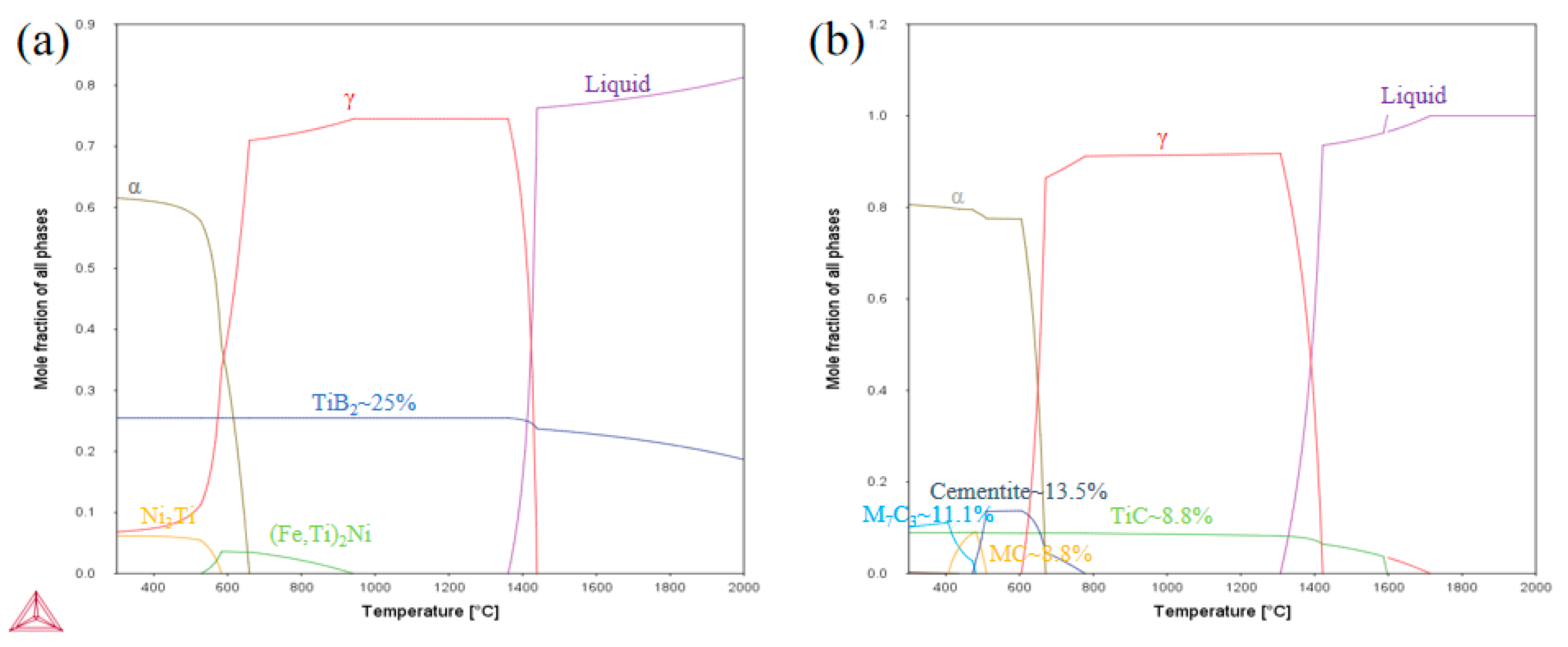
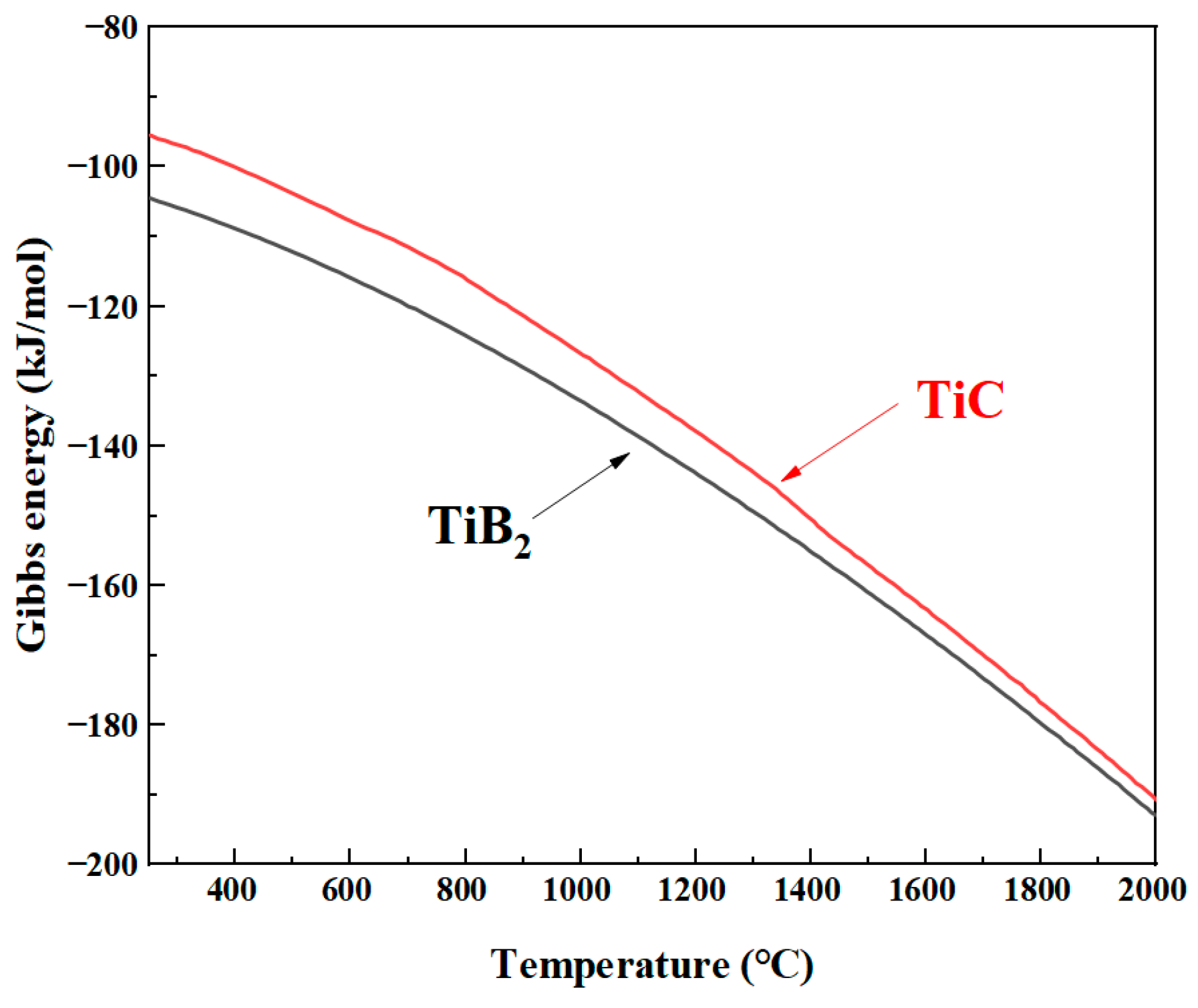
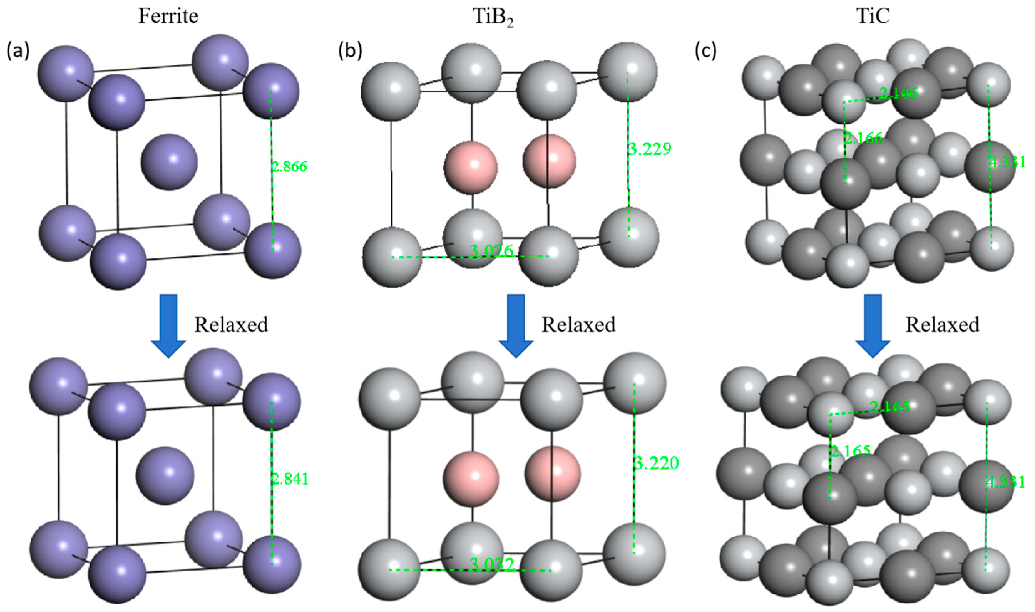
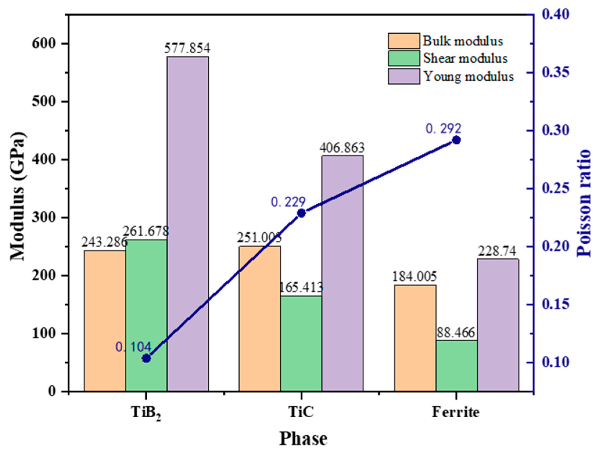
3.1. Thermodynamic Calculations and Elastic Modulus Prediction

Figure 1 shows the phase molar fraction equilibrium diagrams of the two iron matrix composites as a function of temperature. As shown in the Figure 1, both composites are in the liquid phase at 1600 °C; as the temperature decreases, the matrix organization begins to solidify and transform into austenite phase; when the temperature is below 1000 °C, a small amount of (Fe,Ti)2Ni second phase, with a mole fraction of less than 10%, appears in the Fe matrix, as shown in Figure 1a. When the temperature is in the range of 650–700 °C, the matrix FCC austenite phase begins to transform to BCC ferrite phase, while some of the second phase appears with the phase transformation, and the Ni2Ti phase, with a molar fraction of less than 10%, appears in the matrix of Fe/TiB2 composite, and the carbides of Cementite and M7C3 appear in the matrix of the Fe/TiC composite, with molar fractions of 13.5% and 11.1%, as shown in Figure 1b. According to a previous study [17], cementite and M7C3 are brittle phases, so they are generally not used as a component of elastic modulus calculation.
As can be seen in Figure 1a, when the temperature is kept at 1600 °C, a stable TiB2 phase is already present, which may lead to the bonding of the primary reinforced particles during alloy melting and stirring. Therefore, in the preparation of the as-cast composites, Ti is added only after the metal has melted, thus ensuring in situ generation of reinforced particles in the iron matrix by chemical reaction [18]. As the temperature was lowered to 1350 °C, the molten-state alloy was fully solidified, and the mole fraction of the reinforcement particles showed a slight variation, with an increase in the molar fraction of TiB2 of about 8% and TiC volume fraction of about 7.6%. As the reinforced particle, the molar fraction of TiB2 was stabilized at 25% in the range of room temperature to 1350 °C, indicating that the TiB2 reinforced particles have stronger precipitation dynamics with the Fe matrix phase.
Figure 2 demonstrates the trend of Gibbs free energy with temperature for the main reinforced particles of Fe/TiB2 and Fe/TiC composites. It can be clearly seen that both exhibit very low energies in the temperature range from 250 °C to 2000 °C, while TiB2 exhibits lower Gibbs energy than TiC, indicating a stronger bonding ability between Ti-B and a more stable presence in the form of TiB2.
The relaxation processes of the ferrite, TiB2, and TiC phases were simulated using first principles calculation, and the lattice changes before and after relaxation are shown in Figure 3. In particular, the lattice parameter of body-centered cubic ferrite decreases from 2.866 Å to 2.841 Å; the lattice parameter of hexagonal TiB2, a = b = 3.026 Å, increases to 3.032 Å, while c = 3.229 Å decreases to 3.220 Å, and the lattice parameter of face-centered cubic TiC remains unchanged, but the Ti-C interfacial distance decreases from 2.166 Å to 2.165 Å.
Based on Hooke’s law, the elastic constants were derived from the optimized structures of the existing alloys. Hooke’s law describes the response of crystals to external strain and stress tensors. For cubic crystal phases, there are three independent elastic constants: C11, C12, and C44, and their elastic stability can be proven as follows:
C 11 C 12 > 0 , C 11 + 2 C 12 > 0 , C 11 > 0 , C 44 > 0 .
For the close-packed hexagonal TiB2 phase, there are six independent elastic constants (C11, C12, C13, C33, C44, and C66), and their mechanical stability can be proven as follows:
C 44 > 0 , C 11 > C 12 , C 11 + 2 C 12 C 33 > 2 C 13 2
Bulk modulus is a measure of a material’s resistance to compressive deformation, Young’s modulus is a measure of a material’s resistance to uniaxial tensile deformation, and shear modulus is a measure of resistance to shear deformation. In this paper, they are represented by the following equations:
B = C 11 + 2 C 12 3 ,
G = 1 2 C 11 C 12 + 3 C 44 5 + 5 C 44 C 11 C 12 4 C 44 + 3 C 11 C 12 ,
E = 9 B G 3 B + G
ν = E 2 G 2 G
The elastic constants Cij, bulk modulus B, shear modulus G, and Young’s modulus E of ferrite, TiB2, and TiC are shown in Table 2. The elastic modulus of the presented phases is essentially in agreement with the literature values. Small deviations may result from different calculation methods or different experimental conditions, such as the use of different packages such as CASTEP, VASP or ABINIT, as well as the comparison of results calculated at 0 K with those measured at room temperature. In general, the results in the GGA method are usually underestimated by a few percent. This is because the GGA method usually yields longer bond lengths, as well as lower elastic constants and elastic moduli. In order to ensure that the results of all phases are similar to the actual ones, the GGA-PBE model is chosen to be carried out as the exchange correlation function in the next calculations.
Figure 4 illustrates the basic characteristics of TiB2 and TiC-reinforced particles calculated by the first principles approach.
It can be seen that, in the Young’s modulus, a magnitude relationship exists: TiB2 > TiC > ferrite; TiB2 and TiC have larger modulus values thanks to the bonding strength of the Ti-B and Ti-C bonds, and the shear modulus is larger than the bulk modulus of TiB2, which is determined by its unique crystal structure (hexagonal structure). It will be discussed in detail in Section 3.5, and the Poisson’s ratio relationship is ferrite > TiC > TiB2; the small Poisson’s ratio indicates that the transverse deformation of the material is smaller than the longitudinal deformation after the force is applied to the material until it is not plastically deformed, and the ferrite is about 2.8 times that of TiB2, which implies that the bonding interface of the two is prone to segregation due to lattice deformation in the course of the force applied to the material.
The Young’s modulus of the composites tested in this paper is predicted according to the law of mixtures for the calculation of Young’s modulus of particle-reinforced composites [1]:
E c = V m E m E p 1 2 + V p E p E m 1 2 V m E p 1 2 + V p E m 1 2
where E is the modulus of elasticity and the subscripts c, m. and p represent the composite, ferrite, and reinforced particles, respectively, and V is the volume fraction. The theoretical modulus of elasticity was calculated to be 287.70 GPa for Fe/TiB2 composites and 240.56 GPa for Fe/TiC composites.

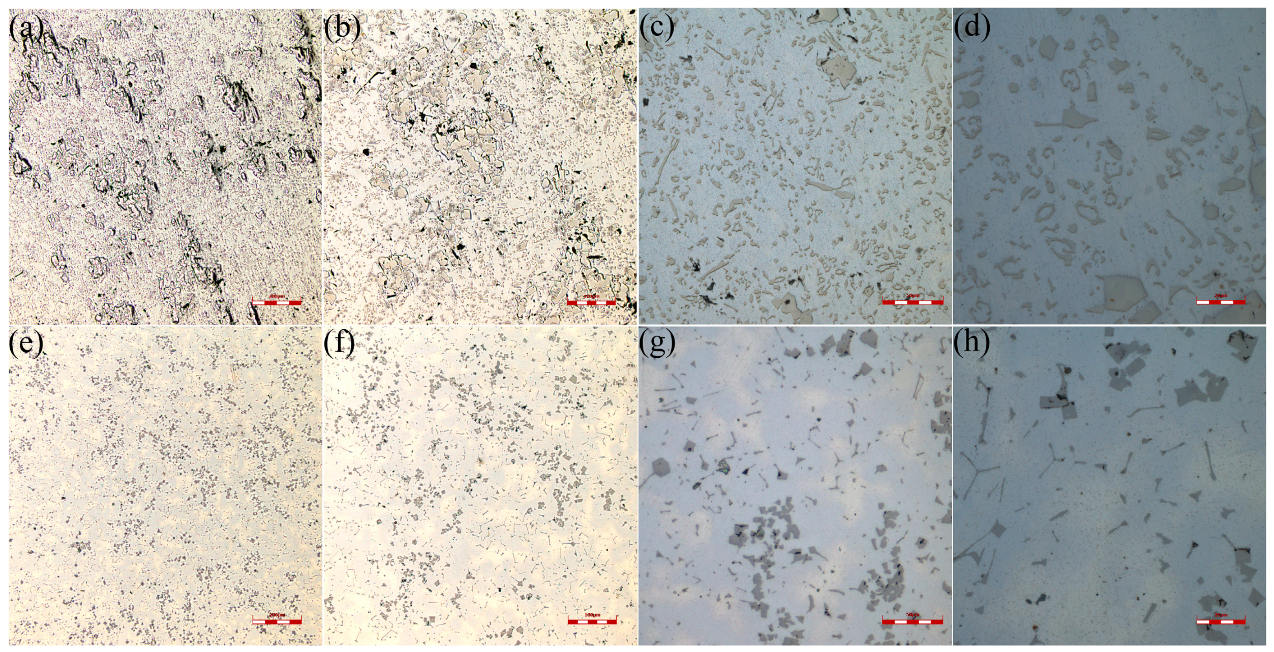
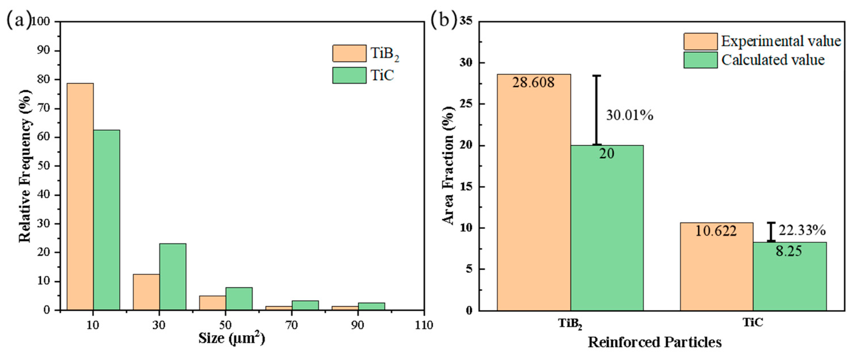
3.2. Microstructure Characterization

Figure 5 illustrates the microstructure of two test composites at the quarter of the ingot lengthwise direction. As shown, the shapes, sizes, and volume fractions of the reinforcing particles of both composites were significantly different.
The TiB2 particles were in the form of lumps, hexagonal rings, and strips, respectively (Figure 5a–d). When the TiB2 molar fraction exceeds 6.3% (~12% by volume) [24], all of them have undergone eutectic reactions during the cooling process, and the composites existed as ferrite, massive TiB2, and eutectic TiB2 at room temperature, while eutectic TiB2 has been shown to be composed of petaloidal/fine columnar and dendritic phases [25]. The long stripey eutectic organization of TiC particles predominate, with a small fraction of coarse massive primary crystals (Figure 5e–h). Both reinforced particles show the phenomenon of “particle bonding” under the microscopy, which is formed by the contact and attachment of the nonmelted hard particles during the smelting and stirring process.
The particle size and area fraction of the reinforced particles in the test composite, Fe/TiB2 and Fe/TiC, were counted, and the results are shown in Figure 6.
The SEM overall microstructure and elemental distribution results of the Fe/TiB2 and Fe/TiC composites are shown in Figure 7.
The addition of Ni in Fe/TiB2 composite materials refines the primary crystal particle size, which is consistent with the literature [5]. At the same time, it avoids a significant impact on the overall volume fraction of the enhancement particles. The TiC particles in Fe/TiC change with the content of Mn, and Mn does not form any carbides in the presence of Ti, only affecting the morphology of TiC particles. By smelting two specific composites, the size of the primary blocky enhancement particles prepared is similar, which facilitates the discussion of the volume fraction. From Figure 6b, it can be seen that the experimentally measured particle fraction is significantly larger than the calculated value. On the one hand, the precipitation order of over-eutectic HMS particles is primary particles—eutectic particles—M3C particles [24], so it is inevitable to include brittle phases other than enhancement particles in the statistical process of enhancement particles, resulting in a larger area fraction than the actual value. According to the thermodynamic calculation in Section 3.1, other precipitated phases that exist at room temperature will appear below 400 °C, which may lead to a larger area fraction than the actual value during the statistical process of enhancement particles; on the other hand, the casting process is a rapid cooling non-equilibrium state, so the low-temperature stable precipitated phases cannot be precipitated in the equilibrium state fraction, but the enhancement particles can maintain a relatively stable volume fraction even in the high-temperature smelting process, so there will be a liquid phase balance volume fraction. In addition, it has been found [9] that TiC begins to nucleate at 1600 °C and presents a regular shape, and TiC reduces the diffusion of carbon during the reaction temperature, leading to the precipitation of M3C and M7C3-type second phases.

3.3. Elastic Modulus and Yield Strength

The elastic modulus cannot be measured accurately by static methods (e.g., tensile, compressive, and three-point bending) due to material and instrumentation properties. The dynamic resonance method, although having a high measurement accuracy, does not nondestructively test the yield strength of the material [26]. In order to comprehensively assess the modulus of elasticity and yield strength of the test composites, the basic mechanical properties of the test composites measured by the dynamic and static methods are used in this section. The data are shown in Table 3.
The yield strengths (Rp0.2) of Fe/TiB2 and Fe/TiC composites measured by the tensile method were 630 MPa and 320 MPa, and the elastic moduli were 210 GPa and 177 GPa, respectively, and the prescribed yield strengths R(pc0.1) of the Fe/TiB2 and Fe/TiC composites measured by the compressive method were 896.83 MPa and 314.11 MPa, respectively. The elastic moduli of Fe/TiB2 and Fe/TiC composites measured by the dynamic method were 226 GPa and 183 GPa, respectively. From the experimental results, it can be found that the elastic modulus measured by the dynamic method was smaller than the value of that tested by the static tensile method. This may be due to the fact that the casting billet smelting process leaves small hole defects, while the tensile test makes the material subjected to the force when the stress uniform distribution occurs, and also, the thickness of the material may affect the measurement, resulting in large results. From Table 3, it can be seen that the yield strength of Fe-TiB2 is much higher than that of Fe-TiC. This is because the hard particle phase can bear the stress from the matrix, so that the material will not enter the yield stage earlier. This load transfer mechanism is one of the main strengthening mechanisms of metal matrix composite materials, which has been reported many times in the literature [23,24,25,26,27]. The yield strength, as the metric for calculating the elastic modulus, is higher for Fe/TiB2 composites than the Fe/TiC composites in terms of both elastic modulus and yield strength, which is consistent with the trend of the reinforced particles in the elastic modulus calculation in Section 3.1 and the volume fraction in Section 3.2.
It is found that the experimentally measured values of the elastic modulus are significantly lower than the theoretically calculated values. According to Figure 1 and Figure 5, it can be seen that, during the melting process, the reinforced particles can exist stably, and “particle bonding” may occur during the smelting and stirring process and remain in the matrix. In addition, there are non-negligible pore defects in the as-cast billet organization, which is the main reason for the lower modulus of elasticity. According to Figure 5, it can be seen that there are primary and eutectic organizations of reinforced particles, and morphologically, the primary crystals are dominated by lumps, while the eutectic organization is dominated by long strips and flaps with high aspect ratios. According to Figure 6, the fine eutectic organization (size < 30 μm2) occupies a large volume fraction, which also causes low elastic modulus. However, compared to Fe/TiC composites, Fe/TiB2 composites have a higher elastic modulus, which is related to its unique crystal structure and interfacial bonding ability and is investigated in detail in the next section.

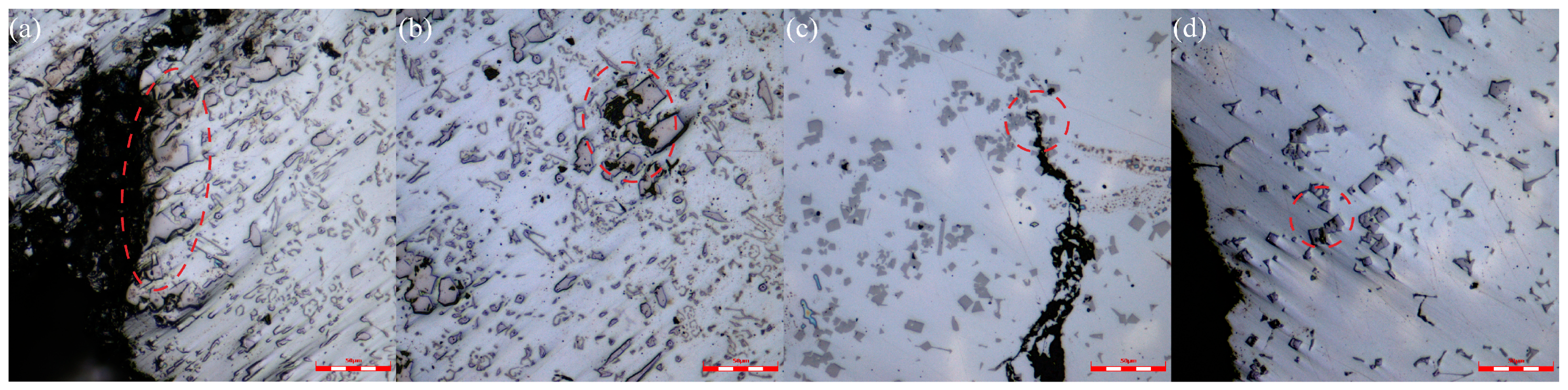
3.4. Analysis of Particle Defect

Increasing the volume fraction of enhancement particles cannot linearly increase the elastic modulus of the material, which is related to the adhesion and pores of the enhancement particles in the material. Figure 8 shows the macro-defects of the cast state of the material [2,27]. Many initial defects, such as particle fracture and interface pores between the particles and matrix, can be seen in the observation area of TiB2 and TiC (especially blocky particles), as shown in Figure 8c. This can be understood from the fact that the composition of these steels is in the hypoeutectic range; the primary δ phase produced by the liquid has a coarse dendritic microstructure, and pores are easily formed between dendritic arms in the latter stage of the casting process. Some of the literature has also proven that the interaction between pores and particles will cause deviations in the elastic modulus of the material [28,29,30,31,32,33].
Figure 9 shows the micropores and crack defects near the fracture of the tensile specimen. Both materials exhibit obvious fracture cracks, and these microcracks mostly occur inside the enhancement particles or at the particle adhesion parts, among which, the main ones are formed in the coarse primary particles.
The phenomenon of pores and microcracks appearing inside or at the interface of coarse primary particles is mainly due to the stress concentration induced by the sharp geometric shape of the enhancement particle terminal [34]. Since the enhancement phase particles are usually much harder than the matrix, a large part of the stress is borne by the enhancement particles in the low stress stage [32,33,35]. As the load continues to increase, the matrix transfers the stress to the nearby enhancement particles until the stress borne by the particles reaches the fracture threshold [31], causing the particles to rupture. Interestingly, the microcracks near the fracture of Fe/TiB2 are mainly inside the coarse primary particles and at the interface, and through Figure 9, it can be seen that a large range of particle adhesion phenomena appear in the composite material, and large-scale coarse particles are also gathered near the fracture crack, so the initial defects left by casting will become the pathway for microcrack expansion [30]. As for Fe/TiC composite materials, weak cracks seem to be stopped by enhancement particles, and the situation where cracks pass through occurs at the interface between particles and matrix, which is in contrast to Fe/TiB2 composite materials.
Micropores in composite materials usually form near the interface between enhancement particles and the matrix [29]. The initial pores of enhancement particles mainly originate from the casting process, and this kind of defect reduces the stress borne by the unit volume material of particles to a certain extent, thereby greatly weakening the strengthening effect of particles as reinforcement on the material and prompting the matrix to enter the yield stage of the material earlier. Generally speaking, with the increase of the volume fraction of enhancement particles, the number of particle fractures and pores caused by the preparation process will also increase [36].

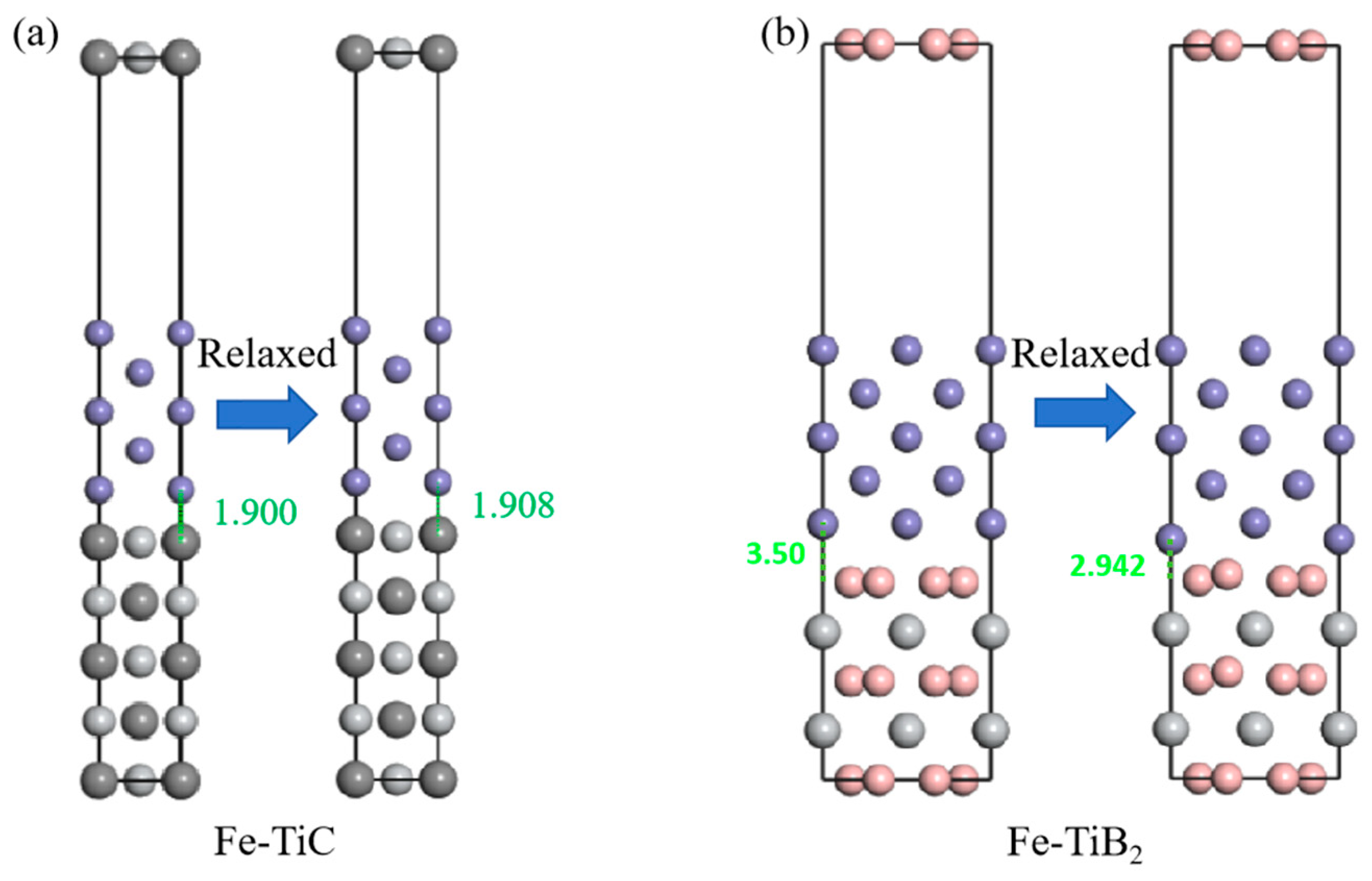
3.5. Work of Adhesion (Wad)

Based on the above study, it is found that the Fe/TiC and Fe/TiB2 composites have tiny cracks inside the particles or at the interface near the fracture, but it is not yet possible to accurately determine the interfacial fracture of the two by tissue observation. The bonding strength of interfacial atoms can be qualitatively described by the interfacial ideal adhesion work (Wad), which is defined as the reversible work required to separate the interface into two free surfaces.
Ferrite is a body-centered cubic structure (space group of Im3m), reinforced particles TiC is a face-centered cubic structure (space group of FM-3M), and TiB2 is a hexagonal structure (space group of P6/mmm) at room temperature. Based on the geometrical model after the structural optimization of Section 3.1, the Fe (100), TiC (100) [15], and TiB2 (0001) [14] were sectioned, respectively. The interfaces of the Fe/TiB2 and Fe/TiC composites were modeled using a superlattice geometry, where the surface of Fe (100) was constructed as having five Fe layers placed on five TiC and TiB2, with the relevant interfaces appropriately invoked in order to accommodate the periodic boundary conditions inherent in the superlattice model calculations. A vacuum layer of 10 Å was created to minimize interactions between adjacent surfaces and to immobilize the two bottom-most layers of atoms in both phases.
The variation of lattice parameters before and after relaxation of the superlattice model is shown in Figure 10.
In order to characterize the bond strength at the two-phase interface, the work of adhesion (Wad) at the interface between the matrix and the reinforced particles is calculated by Equation (8) [15]:
W a d = E F e + E p a r t i c l e E F e p a r t i c l e A
where EFe and Eparticle are the energies after complete relaxation at the surface of the matrix and the surface of the reinforcing particles, respectively, and EFe/particle is the total energy at the interface of the two phases. The results of the adhesion work calculations for the two iron-based composites are shown in Table 4.
The results show that the adhesion work at the Fe (001)/TiB2 (0001) interface (Wad = 3.92 J/m2) is larger than that at the Fe (001)/TiC (001) interface (Wad = 1.77 J/m2), meaning that more coherent interfaces require more energy to disrupt and exhibit higher interfacial strength. The interfacial distance is even smaller (d0 = 1.375 Å), which indicates that the interfacial atomic binding strength is higher, and the interface is more stable.
The bulk phase and the interface can be estimated using Griffith theory:
G b u l k = 2 γ s
G i n t = γ s 1 + γ s 2 γ i n t 12 γ e s
The interfacial fracture of the composite can be expressed by Equations (9) and (10), where γs represents the bulk energy, γs1 represents the surface energy of one part, γs2 represents the surface energy of the other part, γs12 represents the interfacial energy before it breaks into two surfaces, and γes represents the interfacial elastic energy, which can be expressed by Equation (11):
γ e s = G 1 G 2 h | r 1 r 2 | π r 2 ( G 1 + G 2 ) ( 1 + ν 2 ) ln r 2 2 | r 1 r 2 ] + 1
where G1 and G2 refer to the shear modulus of TiB2 or TiC and bcc-Fe, respectively; r1 and r2 denote the diameters of the atoms at the interface; h denotes the average value of the atomic diameters and is calculated as h = (r1 + r2)/2; and ν2 is the Poisson’s ratio of bcc-Fe. Adhesion work Wad is related to γs1, γs2, γint12, and W a d = γ s 1 + γ s 2 γ i n t 12 . Now bring it into Expression (10) to obtain Equation (12):
G i n t = W a d γ e s
Here, the minus sign indicates that the splitting of the interface into two free surfaces releases the elastic energy stored in the system. For a fracture to start at the interface, it requires Gbulk > Gint, which implies a weakly bonded interface. Otherwise, the composite will fail by separating from the interior of the bulk metal matrix or reinforced particles. Due to the differences in the matrix elements of the two composites, there is an error in γes, so this paper performs a qualitative analysis based on Wad. When the composites are subjected to stress and load transfer occurs, if the fracture work borne by the hard coarse particles is greater than that of the interface, the interface will preferentially fracture; if the fracture work borne by the hard coarse particles is less than that of the interface, the fracture occurs within the particles. The hard particles generated by an in situ reaction have the maximum stress they are subjected to, so even if the interfacial bonding relationship is strong, the elastic modulus of the composites is limited by the loss of the hard particles to rupture; according to Table 2 and Table 4, TiB2 has a higher elastic modulus and interfacial work of adhesion of Fe/TiB2, but according to the particles observed in the vicinity of fractured specimens in Figure 9a,b, the TiB2 particles remain stable inside the particles under load conditions, while rupture occurs at some interfaces, indicating that, for the Fe/TiB2 composites, Gint < Gbulk, and also, the large fraction of interfaces at the particle bonding accelerates this phenomenon [37]. In the case of the Fe/TiC composites, micropores existed within the particles before the fracture, as shown in Figure 8, due to the TiC particles being subjected to internal stresses in the microstructure after cooling of the casting, which resulted in the creation of initial pores and, ultimately, cracks, as shown in Figure 9c,d. In conclusion, the in situ reaction generation of reinforced particles by the casting method still has defects, i.e., particle bonding or initial pores, which can cause the actual material properties to be lower than the theoretical values, and the modulation of the smelting process or alloying system is an important method to improve the properties.

4. Summary

In this paper, two typical iron matrix composites were prepared by in situ reaction, their basic mechanical property characteristics were investigated, and the effect of reinforced particles on the interfacial bonding strength with the matrix was analyzed by combining with first principles calculation. The following conclusions were obtained:
(1) The phase characteristics of the two composites were calculated based on thermodynamics and first principles. The calculated values of the elastic moduli of the Fe/TiB2 and Fe/TiC composites at equilibrium are 287.7 GPa and 240.56 GPa, respectively. In addition, we found that the reinforced particles of the two composites can be stabilized in the liquid phase at high temperature, and “particle bonding” during casting may take place and be retained at room temperature.
(2) TiB2 and TiC exist in two morphologies: massive primary particles and eutectic organization., where the eutectic organization of TiB2 is composed of petaloid/fine columnar and dendritic phases, and TiC exists in the form of fine elongated bars. The reinforced particles of both composites consist of more fine eutectic organization and fewer coarse particles, which is related to the primary and eutectic zones that are successively passed through during solidification.
(3) The elastic moduli of the Fe/TiB2 and Fe/TiC composites are 226 GPa and 183 MPa, respectively. The experimentally measured elastic modulus is lower than the equilibrium state calculated value, attributed to particle bonding and pore defects. In addition, holes left over from the casting process are often present inside the coarse primary crystal particles, which become the source of fracture occurrence.
(4) Based on the first principles calculation, it was found that the adhesion work of the Fe/TiB2 composites (Wad = 3.992 (J/m2)) was larger than that of the Fe/TiC composites (Wad = 1.768 (J/m2)), and the interfacial distance of the Fe/TiB2 composites (d0 = 1.375 Å) was smaller than that of the Fe-TiC composites (d0 = 1.908 Å), indicating that the TiB2-reinforced particles have stronger interfacial bonding with the ferrite matrix.

Author Contributions

Conceptualization, H.L. and Y.W.; methodology, Q.Z. and X.F.; software, X.T. and H.L.; validation, Y.W. and M.W.; formal analysis, X.Y. and X.F.; investigation, H.L. and Y.W.; resources, H.L. and X.F.; data curation, H.L. and X.T.; writing—original draft preparation, H.L. Q.Z., X.F. and X.Y.; writing—review and editing, X.F., M.W. and Z.M.; visualization, Q.Z. and X.T.; supervision, X.Y., Y.W. and Z.M.; project administration, Y.W. and Z.M.; funding acquisition, Y.W. and Z.M. All authors have read and agreed to the published version of the manuscript.

Funding

This work was supported by the National Key R&D Program of China (Grant No. 2024YFB3713601).

Data Availability Statement

The original contributions presented in this study are included in the article. Further inquiries can be directed to the corresponding author.

Conflicts of Interest

The authors declare no conflicts of interest.

References

  1. Bonnet, F.; Daeschler, V.; Petitgand, G. High modulus steels: New requirement of automotive market. How to take up challenge? Can. Met. Q. 2014, 53, 243–252. [Google Scholar] [CrossRef]
  2. Hu, Z.; Yin, H.; Li, M.; Li, J.; Zhu, H. Research and developments of ceramic-reinforced steel matrix composites—A comprehensive review. Int. J. Adv. Manuf. Technol. 2024, 131, 125–149. [Google Scholar] [CrossRef]
  3. Baron, C.; Springer, H.; Raabe, D. Combinatorial screening of the microstructure–property relationships for Fe–B–X stiff, light, strong and ductile steels. Mater. Des. 2016, 112, 131–139. [Google Scholar] [CrossRef]
  4. Aparicio-Fernández, R.; Springer, H.; Szczepaniak, A.; Zhang, H.; Raabe, D. In-situ metal matrix composite steels: Effect of alloying and annealing on morphology, structure and mechanical properties of TiB2 particle containing high modulus steels. Acta Mater. 2016, 107, 38–48. [Google Scholar] [CrossRef]
  5. Shi, Z.; Wang, K.; Xie, H.; Dai, L.; Zhao, G. Precipitation of ceramic particles in Fe-TiB2 and Fe-Ni-TiB2 cast steels during the sub-rapid solidification process. J. Alloy Compd. 2023, 943, 169148. [Google Scholar] [CrossRef]
  6. Zheng, S.; Rementeria, R.; Kan, W.; Xu, M.; Huang, J.; Huang, Y.; Pan, X.; Apelian, D.; Liang, Y.; Lin, J.; et al. Nanoparticle enabled high performance high modulus steels. Scr. Mater. 2021, 201, 113954. [Google Scholar] [CrossRef]
  7. Lee, Y.-H.; Kim, N.; Kim, Y.; Cho, S.; Lee, S.-K.; Jo, I. Microstructure and mechanical properties of lightweight TiC-steel composite prepared by liquid pressing infiltration process. Mater. Charact. 2020, 162, 110202. [Google Scholar] [CrossRef]
  8. Tu, X.; Xiao, L.; Zhao, X.; Cai, Z.; Zhao, Z.; Zeng, D.; Wang, S.; Xiao, Y. Microstructure and nanoindentation creep behavior of TiC reinforced steel matrix composite after stabilizing heat treatments. Ceram. Int. 2022, 48, 24733–24744. [Google Scholar] [CrossRef]
  9. Parashivamurthy, K.I.; Mallikarjuna, C. Effect of Manganese on the Microstructure and TiC Precipitation in Hypoeutectoid Steel. Mater. Manuf. Process. 2013, 28, 1161–1165. [Google Scholar] [CrossRef]
  10. Chang, F.; Li, C.-D.; Yang, H.-Y.; Qiu, F.; Shu, S.-L.; Chen, L.-Y.; Jiang, Q.-C. Hot-work die steel with superior mechanical properties at room and high temperatures prepared via a combined approach of composition design and nanoparticle modification. J. Mater. Res. Technol. 2023, 25, 1748–1760. [Google Scholar] [CrossRef]
  11. Lartigue-Korinek, S.; Walls, M.; Haneche, N.; Cha, L.; Mazerolles, L.; Bonnet, F. Interfaces and defects in a successfully hot-rolled steel-based composite Fe–TiB2. Acta Mater. 2015, 98, 297–305. [Google Scholar] [CrossRef]
  12. Dong, W.; Yang, X.; Wang, K.; Liu, B. Research and prospect of particle reinforced iron matrix composites. Int. J. Adv. Manuf. Technol. 2023, 128, 3723–3744. [Google Scholar] [CrossRef]
  13. Sahoo, S.; Jha, B.B.; Mandal, A. Powder metallurgy processed TiB2-reinforced steel matrix composites: A review. Mater. Sci. Technol. 2021, 37, 1153–1173. [Google Scholar] [CrossRef]
  14. Li, Y.; Xiao, B.; Wang, G.; Sun, L.; Zheng, Q.; Liu, Z.; Gao, Y. Revealing the novel fracture mechanism of the interfaces of TiB2/Fe composite from a first principles investigation. Acta Mater. 2018, 156, 228–244. [Google Scholar] [CrossRef]
  15. Yang, J.; Zhang, P.; Zhou, Y.; Guo, J.; Ren, X.; Yang, Y.; Yang, Q. First-principles study on ferrite/TiC heterogeneous nucleation interface. J. Alloy Compd. 2012, 556, 160–166. [Google Scholar] [CrossRef]
  16. ASTM E8; Standard Test Methods for Tension Testing of Metallic Materials. ASTM International: Philadelphia, PA, USA, 2024.
  17. Bohnenkamp, U.; Sandström, R. Evaluation of the elastic modulus of steels. Steel Res. 2000, 71, 94–99. [Google Scholar] [CrossRef]
  18. Anal, A.; Bandyopadhyay, T.; Das, K. Synthesis and characterization of TiB2-reinforced iron-based composites. J. Mech. Work. Technol. 2006, 172, 70–76. [Google Scholar] [CrossRef]
  19. Wang, M. The investigation of dependences of mechanical and electronic properties of TiB2on pressure using the first-principles method. Phys. Scr. 2014, 89, 115702. [Google Scholar] [CrossRef]
  20. Ledbetter, H.; Tanaka, T. Elastic-Stiffness Coefficients of Titanium Diboride. J. Res. Natl. Inst. Stand. Technol. 2009, 114, 333–339. [Google Scholar] [CrossRef]
  21. Li, H.; Zhang, L.; Zeng, Q.; Guan, K.; Li, K.; Ren, H.; Liu, S.; Cheng, L. Structural, elastic and electronic properties of transition metal carbides TMC (TM=Ti, Zr, Hf and Ta) from first-principles calculations. Solid State Commun. 2011, 151, 602–606. [Google Scholar] [CrossRef]
  22. Gilman, J.J.; Roberts, B.W. Elastic Constants of TiC and TiB2. J. Appl. Phys. 1961, 32, 1405. [Google Scholar] [CrossRef]
  23. Feng, K.; Yang, Y.; Shen, B.; Guo, L. In situ synthesis of TiC/Fe composites by reaction casting. Mater. Des. 2005, 26, 37–40. [Google Scholar] [CrossRef]
  24. Springer, H.; Fernandez, R.A.; Duarte, M.; Kostka, A.; Raabe, D. Microstructure refinement for high modulus in-situ metal matrix composite steels via controlled solidification of the system Fe–TiB2. Acta Mater. 2015, 96, 47–56. [Google Scholar] [CrossRef]
  25. Wang, B.; Yi, H.; Wang, G.; Long, Z.; Huang, M. Three-dimensional morphology reconstruction of TiB2 in in situ generated iron-based composites. J. Met. 2019, 55, 133–140. [Google Scholar]
  26. Lord, J.D.; Morrell, R.M. Comparison of static and dynamic methods for measuring stiffness of high modulus steels and metal composites. Can. Met. Q. 2014, 53, 292–299. [Google Scholar] [CrossRef]
  27. Wang, X.; Leng, H.; Han, B.; Wang, X.; Hu, B.; Luo, H. Solidified microstructures and elastic modulus of hypo-eutectic and hyper-eutectic TiB2-reinforced high-modulus steel. Acta Mater. 2019, 176, 84–95. [Google Scholar] [CrossRef]
  28. Wang, K.-Y.; Ke, Y.-J.; Wang, J.-S.; Liu, X.-G.; Zhang, W.-W.; Guo, Y.; Sasaki, G. Systematic investigation of the microstructure evolution and dynamic recrystallization mechanisms of as-cast Fe–TiB2 composites under different hot deformation parameters. J. Mater. Res. Technol. 2023, 27, 2833–2846. [Google Scholar] [CrossRef]
  29. Chen, R. Effect of particle morphology on fatigue crack propagation mechanism of TiB2-reinforced steel matrix composites. Eng. Fract. Mech. 2022, 274, 108752. [Google Scholar] [CrossRef]
  30. Wang, Z.-J.; Zhang, W.-N.; Li, Y.-W.; Wang, G.-D.; Liu, H.-T. Heterogeneous nucleation of M2B-type borides (M = Cr, Fe) attached to TiB2 and Ti(C,N) particles in as-cast high borated steel. Mater. Charact. 2020, 169, 110588. [Google Scholar] [CrossRef]
  31. Li, B.; Xu, K.; Chen, R.; Li, Y.; Wang, X.; Jiang, C.; Huang, M. On the fatigue crack propagation mechanism of a TiB2-reinforced high-modulus steel. Compos. Part B Eng. 2020, 190, 107960. [Google Scholar] [CrossRef]
  32. Chawla, N.; Andres, C.; Davis, L.C.; Jones, J.W.; Allison, J.E. The interactive role of inclusions and SiC reinforcement on the high-cycle fatigue resistance of particle reinforced metal matrix composites. Met. Mater. Trans. A 2000, 31, 951–957. [Google Scholar] [CrossRef]
  33. Tekmen, C.; Ozdemir, I.; Cocen, U.; Onel, K. The mechanical response of Al–Si–Mg/SiCp composite: Influence of porosity. Mater. Sci. Eng. A 2003, 360, 365–371. [Google Scholar] [CrossRef]
  34. Bindumadhavan, P.; Wah, H.K.; Prabhakar, O. Assessment of particle–matrix debonding in particulate metal matrix composites using ultrasonic velocity measurements. Mater. Sci. Eng. A 2002, 323, 42–51. [Google Scholar] [CrossRef]
  35. Kumar, A.; Jha, P.K.; Mahapatra, M.M. Abrasive Wear Behavior of In Situ TiC Reinforced with Al-4.5%Cu Matrix. J. Mater. Eng. Perform. 2014, 23, 743–752. [Google Scholar] [CrossRef]
  36. Hadjem-Hamouche, Z.; Derrien, K.; Héripré, E.; Chevalier, J.-P. In-situ experimental and numerical studies of the damage evolution and fracture in a Fe-TiB2 composite. Mater. Sci. Eng. A 2018, 724, 594–605. [Google Scholar] [CrossRef]
  37. Zhang, H.; Springer, H.; Aparicio-Fernández, R.; Raabe, D. Improving the mechanical properties of Fe—TiB2 high modulus steels through controlled solidification processes. Acta Mater. 2016, 118, 187–195. [Google Scholar] [CrossRef]
Figure 1. Phase transformation and precipitation patterns of second-phase particles in the equilibrium state of the test composites: (a) Fe/TiB2; (b) Fe/TiC.
Metals 15 00129 g001
Figure 2. Plot of Gibbs free energy versus temperature for the main reinforcing particles of two iron-based composites.
Metals 15 00129 g002
Figure 3. Crystal structure models before and after relaxation: (a) ferrite; (b) TiB2; (c) TiC.
Metals 15 00129 g003
Figure 4. Modulus and Poisson’s ratio of TiB2, TiC, and ferrite.
Metals 15 00129 g004
Figure 5. Microstructure characterization of the cast test composites at different magnifications. Fe/TiB2: (a) 10×; (b) 20×; (c) 50×; (d) 100× and Fe/TiC: (e) 10×; (f) 20×; (g) 50×; (h) 100×.
Metals 15 00129 g005
Figure 6. Statistical plot of the relationship between particle size and area fraction of reinforced particles for the test composites. (a) Particle size distribution diagram; (b) Experimental and Calculated Statistics of Particle Fractions.
Metals 15 00129 g006
Figure 7. Particle morphology and EDS mapping analysis of composites: (a) Fe/TiB2; (b) Fe/TiC.
Metals 15 00129 g007
Figure 8. The optical microstructure of particle bonding and void defects in two types of composites: (a,b) Fe/TiB2; (c,d) Fe/TiC.
Metals 15 00129 g008
Figure 9. Microscopic voids and crack defects near the fracture of two types of composite materials are shown. (a,b) Fracture cracks in Fe/TiB2 extend within the reinforced particles and interface. (c,d) Fracture cracks in Fe/TiC extend within the reinforced particles and interface.
Metals 15 00129 g009
Figure 10. Interfacial structure model before and after relaxation. (a) Fe/TiC composite; (b) Fe/TiB2 composite.
Metals 15 00129 g010
Table 1. Chemical composition of test composites (wt%).
CompositeTiBNiMnCCrFe
Fe/TiB210.103.8610.002.00--Bal.
Fe/TiC4.00-0.0056.001.800.15Bal.
Table 2. Calculated elastic constants, bulk modulus B, shear modulus G, Yong’s modulus E, and B/G of TiB2, TiC, and ferrite. The units for elastic constants, B, G, E, and C11–C66 are GPa.
PhaseSpeciesC11C12C13C33C44C66BGE
TiB2Present638.752.689.3449.8258.3293.1243.3261.7577.9
Cal. [19]653.064.0101.0455.0260.0294.5253.0260.0580.0
Exp. [20]654.449.095.3458.1262.3302.7247.5264.3584.7
TiCPresent487.0132.9 157.7 251.0165.4406.9
Cal. [21]507.1121.3 171.5 249.9180.1435.0
Exp. [22]500.0113.0 175.0 242.0182.0437.0
FerritePresent265.6143.2 106.6 184.088.5228.7
Exp. [23]243.1138.1 121.9 173.194.1239.0
Table 3. Basic mechanical properties of test composites.
CompositeTest MethodsElastic Modulus (GPa)Yield Strength (MPa)
Fe/TiB2dynamic method210-
Static method
(tension method)
226630
Static method
(compression method)
-897
Fe/TiCdynamic method177-
Static method
(tension method)
183320
Static method
(compression method)
-314
Table 4. Interfacial ideal adhesion work Wad and interfacial distance d0 for the Fe/TiB2 and Fe/TiC interfaces.
SystemAdhesion Work Wad (J/m2)Interface Distance d0 (Å)
Fe/TiB23.9221.375
Fe/TiC1.7681.908
Disclaimer/Publisher’s Note: The statements, opinions and data contained in all publications are solely those of the individual author(s) and contributor(s) and not of MDPI and/or the editor(s). MDPI and/or the editor(s) disclaim responsibility for any injury to people or property resulting from any ideas, methods, instructions or products referred to in the content.

