Review

Enrichment Methods for Metal Recovery from Waste from Electrical and Electronic Equipment: A Brief Review

by
Ernesto Chicardi
1,*,
Antonio Lopez-Paneque
2,
Victoria Humildad Gallardo García-Orta
3,
Ranier Enrique Sepúlveda-Ferrer
1 and
Jose Maria Gallardo
1
1
Departamento de Ingeniería y Ciencia de los Materiales y del Transporte, Escuela Técnica Superior de Ingeniería, Universidad de Sevilla, Camino de los Descubrimientos, s/n, 41092 Sevilla, Spain
2
Asociación de Investigación y Cooperación Industrial de Andalucía (AICIA), Camino de los Descubrimientos, s/n, 41092 Sevilla, Spain
3
Atlantic Copper, S.L.U., Francisco Montenegro Avenue, 21001 Huelva, Spain
*
Author to whom correspondence should be addressed.
Metals 2025, 15(2), 140; https://doi.org/10.3390/met15020140
Submission received: 30 November 2024 / Revised: 22 January 2025 / Accepted: 28 January 2025 / Published: 29 January 2025

Abstract

:
The growing global demand for minerals and metals, coupled with fluctuations in pricing and market disruptions, has emphasised the critical role of these resources in sustaining the global economy. Waste from Electrical and Electronic Equipment (WEEE) has emerged as a promising source of raw materials, particularly for metal recycling and the valorisation of plastic fractions. In 2022, approximately 62 million metric tons of e-waste were generated worldwide, with projections indicating a rise to 74 million metric tons by 2030. Despite the significant volume of WEEE, only 17.4% was collected and recycled, which reveals a considerable opportunity for resource recovery. This review highlights the composition of metals in WEEE, which includes valuable precious metals, such as gold, silver, and palladium, alongside base metals, such as copper and aluminium. The review also discusses current methodologies for metal recovery and focuses on mechanical size-reduction techniques and various physical separation methods, including a shaking table, magnetic, electrostatic, and eddy current separation, flotation, and the use of a hydrocyclone. These technologies play a vital role in enhancing recovery efficiencies, thereby contributing to sustainable practices in the recycling industry. Thus, the works evaluated in this paper reveal the possibility of recovering more than 90 wt.% of precious (Ag, Au, Pd, Pt) and main metals (Cu, Sn, Al, Fe, Ni) by a combination of these mechanical size-reduction and physical separation methods.

1. Introduction

Many nations depend heavily on importing vital raw materials to support their industrial sectors. The growing global demand for minerals and metals, combined with fluctuations in pricing and market disruptions, has underscored the critical role these resources play in sustaining the global economy [1]. An increasingly studied, addressed, and potentially applied option involves the use and recycling of Waste from Electrical and Electronic Equipment (WEEE) as a source of raw materials, with particular emphasis on metal recycling and the valorisation of plastic and/or polymeric fractions. The global and average percentages of materials existing in WEEE are shown in Figure 1, based on the data revealed by Charitopoulou et al., Achilias et al., and Martelo et al. [2,3,4]).
In this respect, WEEE is growing at an alarming rate and is now even considered one of the fastest-growing waste streams globally, with approximately 53.6 million metric tons (Mt) of e-waste generated worldwide in 2020. In 2022, the world generated 62 million metric tons (Mt) of WEEE, a sharp 82% increase from 2010. Increasing even further, this value is expected to climb to 74 million metric tons by 2030, which reflects an annual growth rate of 3–5%. In contrast, despite the large volume, only 17.4% of this e-waste was properly collected and recycled worldwide, which suggests an outstanding opportunity for it to be used as a source of raw materials. In Europe, which constitutes the region with the highest WEEE recycling rate, approximately 42.5% of generated WEEE is processed adequately. However, regions such as Asia and the Americas report much lower recycling rates, with only 11.7% and 9.4%, respectively. Africa and Oceania show even lower figures, with 0.9% and 8.8% of WEEE being recycled [5]. According to Tiwary et al. [6], WEEE generation in Asia is projected to surpass 35 Mt annually, making it a significant source of WEEE that could further challenge the global recycling infrastructure. Table 1 presents a statistical summary of WEEE generation and recycling per continent.
Regarding the valorisation of WEEE, it contains a large quantity of valuable metals, such as silver (Ag), gold (Au), and copper (Cu), which, if efficiently recovered, could generate substantial economic value. In 2022 alone, the metals in WEEE were estimated to be worth approximately USD 91 billion globally, but much of this potential was lost due to inadequate recycling systems. If recycling rates increase to 60% by 2030, it could lead to net economic benefits of USD 38 billion worldwide. This aspect suggests an impressive economic impact and the major potential benefits of the WEEE-metal-recycling industry [7].
Table 1. WEEE generation and recycling per continent (data collected from 2014 to 2021).
RegionWaste Generated (Mt)Waste Recycled (Mt)Recycling Rate
(%)
Source
Asia26.23.111.7[6,8]
America14.31.39.4[1,9]
Europe12.25.242.5[1,10]
Africa3.10.030.9[11]
Oceania0.80.078.8[9,12]
The rapid increase in WEEE generation, coupled with low global recycling rates, underscores the urgent need for stronger regulations and improved recycling infrastructure to prevent the loss of valuable resources and to mitigate environmental damage. Furthermore, the potential large-scale recycling of WEEE has one major drawback: most printed circuit boards (PCBs) contain a complex array of toxic materials. These toxins render PCBs hazardous waste that must be handled with care. According to the US Environmental Protection Agency, between 80 and 85% of WEEE is traditionally sent to landfills, which allows leachate to contaminate the soil and groundwater in surrounding regions. Moreover, the traditional incineration of PCBs can lead to the evaporation of heavy metals and the release of harmful dioxins and furans, which pose a serious threat to health [8,13]. The recycling of WEEE using environmentally friendly methods is therefore still under development. Researchers need to provide a valid solution to protect the environment from these hazardous materials and to recover the most valuable metals [8].
Therefore, the main goal of this review is to show the main findings on physical technologies for metal recovery from e-waste, including the initial required mechanical size-reduction techniques and various physical separation methods, such as a shaking table, magnetic separation, electrostatic separation, eddy current separation, flotation, and a hydrocyclone.

2. Research Methodology

The articles used for this review were retrieved from scientific databases, mainly from the Web of Science and Scopus, complemented with ScienceDirect, SpringerLink, IEEE Xplore, SciFinder, and SciELO. This research was conducted using combinations of different keywords, including “metal recovery”, “WEEE”, “e-waste”, “PCBs”, “physical separation methods”, “size reduction”, “mechanical processes”, “composition in WEEE”, “Shredder”, “hammer mills”, “electrostatic separation”, “magnetic separation”, “cryomilling”, “cryogenic milling”, “cryogenic grinding”, “Eddy current separation”, “Foucault’s separation technology”, “inverse flotation”, “direct flotation”, “shaking table”, and “hydrocyclone”, among others. Boolean operators such as “and”, “or”, “not”, “parentheses”, and “quotation marks” were used to refine the results.
The results obtained were narrowed down to the last 20 years, i.e., from 2004 up to 2024. Works published before 2004 were only considered according to their valuable information. Thus, an initial number of more than 250 published articles was selected as potential articles for this review.
At this point, a second selection step was applied, keeping only those papers based mainly on physical separation and size-reduction techniques and with information dealing with the composition and percentages of the separation of phases.

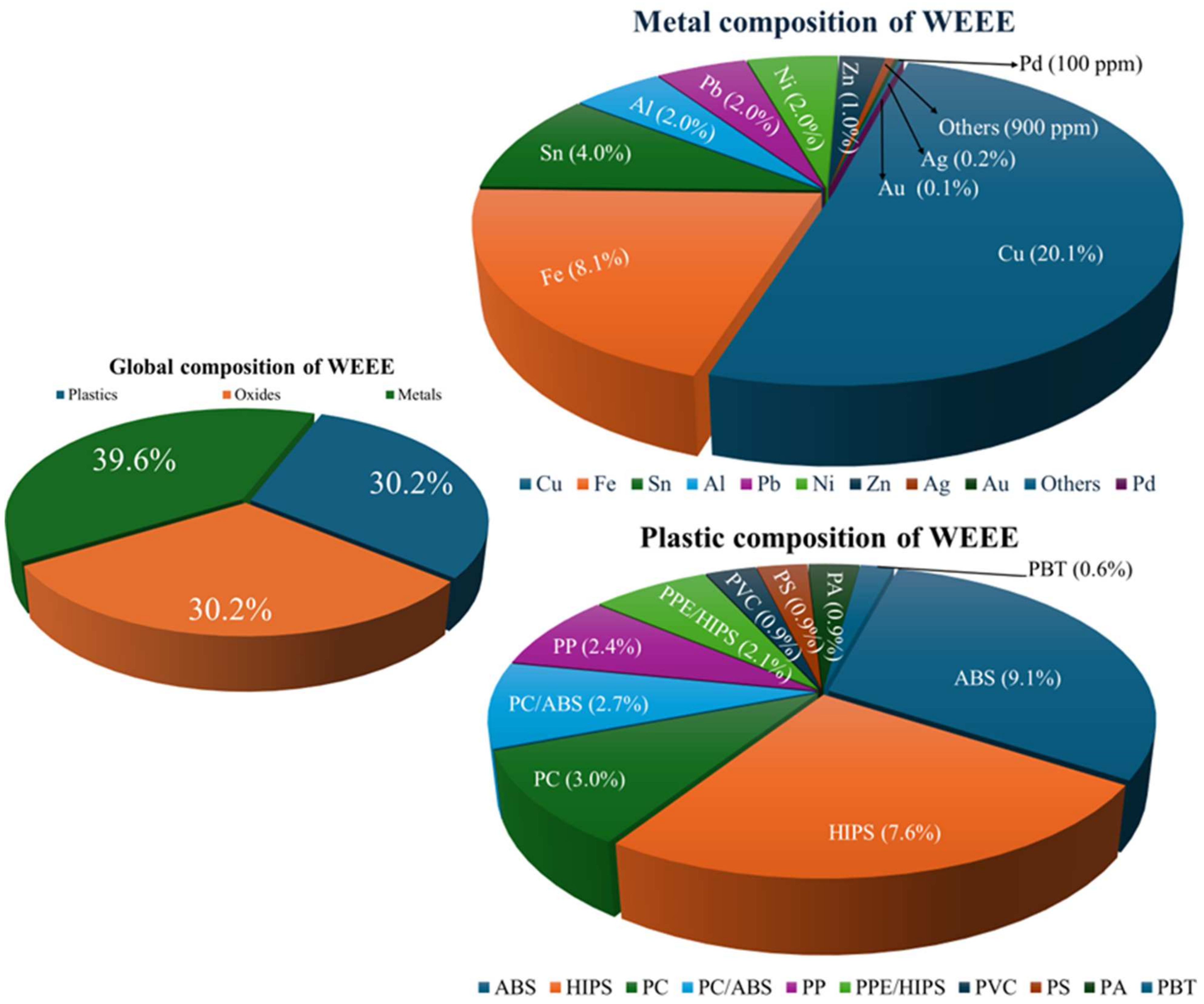
3. Composition of Metals in WEEE

The percentage of metals susceptible to valorisation and recycling from WEEE reaches values close to 40 wt.% (Figure 1). In this respect, WEEE contains a wide variety of metals, ranging from precious metals, such as gold, silver, palladium, and platinum, to basic and industrial raw materials, such as copper, aluminium, nickel, iron, zinc, and tin.
Due to the wide range of WEEE classes, such as evolving end-of-life informatics and telecommunication devices (computers, laptops, tablets, mobiles, printers, scanners), large household devices (refrigerators, freezers, washing machines, ovens), small household devices (microwaves, mixers, toasters, coffee makers, vacuum cleaners), entertainment and audiovisual devices (TV, monitors, digital cameras, sound systems), electronic toys (videogame consoles, electronic games), and small electronic devices (digital watches, calculators), its composition varies widely, as illustrated in Table 2. Its recycling potential depends largely on its composition, the efficiency of the separation process, and the recovery technologies involved.
For example, the printed circuit boards (PCBs) of electronic devices contain a significant amount of noble metals, particularly gold (Au), silver (Ag), and palladium (Pd). These metals are crucial for their electrical conductivity and corrosion resistance, which make them valuable for recovery. Gold, for instance, is used in connectors and switches, while silver is often found in solder and connectors. Palladium is used in multi-layer ceramic capacitors. According to the data compiled by Holgersson et al. [14], gold concentrations in mobile phone PCBs can reach up to 1083 ppm, while silver and palladium are found in concentrations of 2773 ppm and 55 ppm, respectively. These concentrations are higher in smaller devices such as smartphones and mobile phones due to the compact design and higher metal density. In turn, copper (Cu) is the most abundant base metal in WEEE, particularly in PCBs, where it serves as the primary conductive material. Specifically, copper is the major component in cables, connectors, and PCBs, with its proportion typically ranging between 10 and 20 wt.% [15]. The average copper content in WEEE varies between 20 and 45%, depending on the type of device. In informatic technology and telecommunication equipment, copper concentrations are particularly high, reaching up to 45% [16]. The recovery of copper from WEEE is essential not only because of its economic value but also due to its potential environmental impact when not properly recycled. Ou et al. [17] reported that copper in PCBs could be effectively recovered through mechanical and chemical processes, whereby yields of up to 90% can be achieved through sulfuric acid leaching and mechanochemical treatments.
Thus, the metallic fraction of end-of-life (EoL) PCBs represents a wide range of metals, including copper, palladium, lead, tin, cadmium, silver, gold, gallium, indium, titanium, silicon, germanium, and arsenic. This diversity of metals highlights the economic importance of recycling these components [18].

4. Current Methods for Metal Recovery

The operations required for the recycling of WEEE involve the sequential application of several stages, starting with mechanical treatments to reduce the particle size of WEEE, followed by more advanced physical and/or biological separation processes to extract valuable metals. In this context, the first process covers traditional size-reduction, comminution, or break-down techniques aimed at mechanically releasing metals from non-metal phases such as plastics and ceramics. Common size-reduction methods include shredding, hammer milling, knife milling, disc milling, and other more recent advanced mechanical size-reduction techniques such as cryogenic milling, more commonly referred to as cryomilling [19]. Subsequently, physical methods such as magnetic, electrostatic, eddy current, and flotation separation techniques can be employed to isolate valuable metallic compounds from non-metallic compounds, based on different physical properties. Furthermore, other separation technologies include the use of the chemical and biological properties of the materials, such as pyrometallurgical, hydrometallurgical, and biometallurgical methods. However, these techniques lie outside the scope of this review, which is based solely on physical separation techniques.
Lastly, the full process for the recovery of metals from WEEE can be complex, as can be observed from the recycling flowsheet of refrigerator waste (Figure 2a) and TV and CRT waste (Figure 2b), evolving from a manual or assisted dismantling process to fully automatic systems. Effluent gases and/or liquid must be collected and properly disposed of. Also, dust control systems must be implemented to reduce the risk of fire. WEEE material overheating must be prevented, as well as the formation of toxic plastic gases during processing.

4.1. Size-Reduction Techniques

Size reduction is a critical step in metal recovery since it liberates the metals from the non-metallic components of WEEE. Many authors have proposed and asserted that it is necessary to reach a precise particle size, or liberation size, of at least 1 mm. Otsuki et al. [21] observed that the degree of liberation is always increased by a reduction in particle size, reaching a value of 85 unlocked metal particles when the size of crushed PCBs reached values between 0.125 and 0.300 mm. Yamane et al. [22] point out that metals in polymers and ceramics are not fully accessible in particles larger than 1 mm. Specifically, Kaya et al. [23] and Arshadi et al. [24] have determined the concentration of metals in fractions with particle sizes smaller than 1 mm. Other authors have found that to reach the 100% liberation of diverse metals, it is necessary to attain a different particle size. Ogunniyi et al. [25] obtained the total liberation of all materials from particles of 75 microns in size. Zhao et al. [26] demonstrated the full liberation of Cu from PCBs with particle sizes of less than 250 microns. Zhang S et al. [27] achieved the 100% liberation of the majority of metals in PCBs when they were reduced to 600 microns, while Wen et al. [28] reproduced the same full liberation of metals from PCBS with a reduced size of 500 microns. Therefore, the use of appropriate reduction processes is essential for the subsequent stages of separation of the different metal fractions contained in WEEE. In this section, a brief presentation is therefore provided of the most common techniques applied.
Shredding is one of the most common techniques for initial size reduction. In this process, electronic equipment is cut into smaller pieces by a shredding unit typically made of a low-speed single- or two-shaft cutting system with rotary knife-discs, which facilitates the subsequent comminution into smaller sizes by subsequent devices. Lee et al. [29] observed two different liberation sizes for WEEE from refrigerators and small appliances, such as electric heaters, VCRs, and vacuum cleaners. For mid-sized refrigerators and small appliances with 50 mm fragments, 95% liberation was achieved, but for smaller equipment, such VCRs and other devices containing a higher amount of electronic parts (PCBs), 20–35 mm of discharge clearance was necessary for the same degree of liberation. Moreover, the average particle size required to attain the 95% liberation of metals, such as Al and Cu, was smaller than that for iron or plastic. Chancerel et al. [30] carried out two consecutive shredding processes on different WEEE types with manual and automatic sorting to optimise the process. Furthermore, they suggest a preference for the manual separation of relevant parts with relevant materials in comparison to the alternative of shredding and the consequent dispersion and losses of precious metal content.
In the case of PCBs, they are usually flat with sizes of 460 × 610 mm (larger PC units), 250 × 300 mm (Desktop PC), or just 20 × 30 mm (smartwatch). As a result, shear forces are more effective in reducing their size with a negligible increase in temperature during the process. The reduction in size is linked to the dimension and shape of the rotary knife-discs, since the minimum reduction could be estimated as the thickness of the disc, multiplied by the perimeter of the disc, and divided by the number of teeth; that is, a three-toothed knife-disc of 50 mm in diameter by 15 mm in thickness will produce PCB strips of 15 mm in height by 52 mm in length. Therefore, two-shaft or four-shaft (for regrinding) cutting systems with a 3–5-toothed knife-disc are preferred, as they offer significant size reduction with lower consumption per process. For instance, Wang et al. [9], Zhang, S. et al. [31], and Touze et al. [31] used a shredder device for cutting PCBs and attained particles sizes of 1–2 mm. Lastly, Oliveira et al. [32] applied a two-combination step for a shredder mill (Erdwich mod. EWZ 200, Igling, Germany) and a disc cutting mill (Retsch mod. SM2000, Hann, Germany) to obtain 1 mm milled PCBs.
Subsequent to the primary mill with a shredder, secondary mill steps usually involve the use of hammer mills. During this process, mechanical forces such as impact, shear, and compression are employed to break the WPCBs into increasingly smaller fragments. These mills reduce material to sizes between 0.5 mm and 5 mm, thereby allowing subsequent separation processes to operate more effectively [15]. Ellamparuthy et al. [12] observed that producing particle sizes smaller than 750 microns typically requires a three-stage milling process. To achieve finer particle sizes, such as 500 microns, at least four stages are needed, and for particles as small as 250 microns, up to twelve crushing stages are necessary. These findings underscore the fact that a significant reduction in particle size increases the number of required hammer milling stages. As noted by Wang et al. [9], two-step crushing involving a shearing machine and a hammer grinder is often used to fragment WPCBs. Due to the possible oxidation of metal during milling, it is possible to employ inert gas as nitrogen or argon during the hammer milling process. Furthermore, continuous milling increases the temperature of the PCBs which may result in pyrolysis or the agglomeration of the particles [33]. Also, Lee et al. [34] studied the effect of using a hammer rotational mill at different speeds of 1600, 2000, and 2400 rpm, together with screen aperture (0.7, 1, and 1.4 mm) and the initial feed size (4, 6, and 8 mm), on the final particle size of the crushed PCBs. It was observed that there was no effect of the hammer milling rotation speed on the final distribution of particle size, reaching values up to 0.1 mm with an 80th percentile between 1.1 and 1.3 mm in all cases. On the contrary, the decrease in the screen aperture size and the feed size allowed the authors to obtain a particle size distribution with an 80th percentile up to 0.52 mm. Table 3 shows a summary of the most common reduction technologies utilised to reduce PCBs.
Cryomilling, otherwise known as cryogenic grinding, is a process in which materials, in this case, electronic waste (WEEE), are cooled to extremely low temperatures using cryogenic agents such liquid nitrogen (−198.5 °C) and dry ice (−78.5 °C). The purpose of this cooling is to produce material embrittlement, making them easier to crush and pulverise. In the recycling of electronic waste, cryomilling is particularly useful to reduce the size of difficult-to-handle materials, such as plastics, metals, and compounds found in printed circuit boards (PCBs). At low temperatures, the materials become fragile and brittle, allowing them to be broken into finer particles under the action of impact and abrasion forces. This is especially important for the following: (a) liberating valuable metals contained in PCBs by better separating metallic from non-metallic parts; (b) preventing the formation of agglomerates of plastic materials, which tend to be softer and more difficult to process at room temperature; (c) reducing wear on the equipment, since at lower temperatures, the abrasive behaviour of some materials is reduced; and (d) preventing bromine evaporation. This process is therefore highly efficient in achieving a fine fragmentation of WEEE and improving the efficiency of subsequent stages of separation and metal recovery. In this context, Tiwary et al. [6] applied cryogenic grinding with a continuous flow of liquid N2 on an optical mouse PCB to break it up into a nanoparticle, reaching particle sizes of less than 200 nm, which are essentially single-phase particles, therefore showing a major advantage when separating various metallic and non-metallic fractions. Nekouei et al. [5] treated pre-crushed PCBs and used cryogenic grinding in a laboratory-scale high-energy vibratory mill, where particles with sizes of approximately 40 nm were obtained [44]. Holgersson et al. [14] used a cryo-centrifugal mill under cryogenic conditions to reduce the particle size of PCB fractions from 3 cm × 3 cm to sizes smaller than 250 microns for subsequent chemical digestion and the determination of its metal content. Suponik, T. and his collaborators [45] demonstrated that using a knife mill under cryogenic conditions (below −150 °C) reduced 3 cm × 3 cm pieces of PCBs down to less than 700 microns.
Moreover, Zhou et al. [46] conducted an interesting study based on the direct cryogenic grinding of pre-treated PCB scrap at 3.5 mm. Cryogenic milling at −30 °C for 5 min was carried out using a shredder mill and produced a 95 wt.% of PCBs of particle sizes from approximately 3.0 mm to 0.1 mm. Subsequently, the air table separation technique was employed to sort this WEEE into fractions of different sizes and compositions. Specifically, the recovery rate of metal on the 0.5–1.2 mm grade was 94.6%. The schema of these interesting results is reproduced in Figure 3.
At this early stage, it can be corroborated that cryomilling has the potential ability to reduce particle size not only down to micrometric size but also down to nanometric size, and to provide the positive separation and liberation of metallic and non-metallic fractions. However, since most of these studies were conducted on a lab scale at Technology Readiness Level 4, the use of cryomilling still needs to be demonstrated and implemented on an industrial scale, as a system or prototype in a real environment (TRL 7).

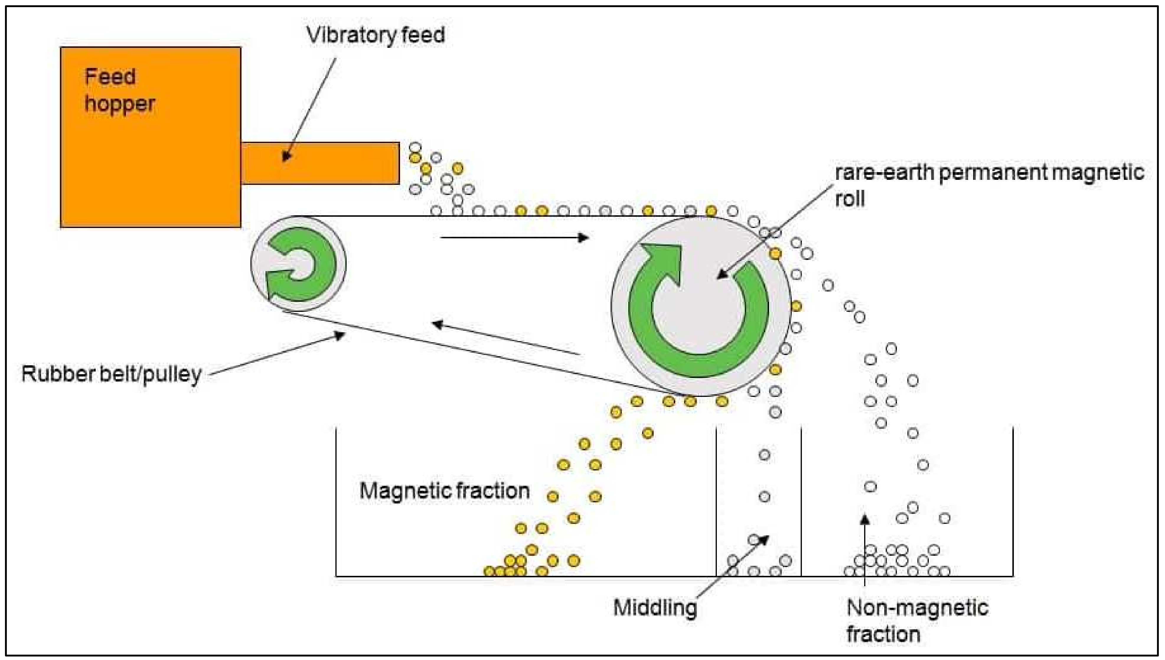
4.2. Physical Separation Technologies

The first physical separation technique showcased here is the shaking table, also known as the Wilfey table. This is a device that uses the movement and inclined flow of a table to separate materials based on different densities. During operation, a slurry of the material is fed onto the deck, and the table’s oscillatory motion, combined with water flow, facilitates the separation of particles according to their densities. However, the effectiveness of a shaking table depends on many other parameters, such as particle size, shape, deck inclination, stroke length, and water flow rate. The proper optimisation of these variables is crucial to achieving efficient separation and high recovery rates of materials [47].
Thus, in the context of crushed e-waste and, more particularly, PCBs, shaking tables are used to discriminate between and separate metallic particles and non-metallic components, such as plastic and fibres, according to their clear different densities. Arshadi et al. [24,48] used the shaking table to determine the concentration of metals in crushed PCBs. Concurrently, three different fractions with particle sizes less than 1 mm, 1–3 mm, and 3–8 mm were used in the shaking table, isolating plastic with average values of 57.6 wt.%, 38.3 wt.%, and 45.0 wt.%, respectively. Also, Burat et al. [49] applied a combined physical separation method (shaking table, and magnetic and electrostatic separation) to obtain concentrated metallic fractions from crushed PCBs. Specifically, around 67 wt.% of the feed was separated in the shaking table. There, the three fractions separated corresponded to a 33.3 wt.% of a metal concentrated fraction, 9.8 wt.% of a middling fraction, and 56.9 wt.% of a tailing fraction. Meanwhile, the first fraction was composed mainly of Cu (33.8 wt.%), Fe (13.1 wt.%), and Al (12.9 wt.%), and in the other two fractions, the amount of metal is residual, with Al being the main metallic material, with percentages around 4–6 wt.%. Finally, Lui et al. [50] studied the effect of the shaking table on the concentration of mainly Cu in different particle size fractions of pulverised PCBs. They obtained Cu recovery values between 83 and 95 wt.%, depending on the feed particle size. Overall, the best feed grain size was 0.074–1 mm.
On the other hand, magnetic separation is one of the most straightforward methods for recovering ferrous metals (e.g., iron, steel, nickel, cobalt, and a number of their alloys and compounds) from WEEE. It is commonly used as a pre-treatment step before other metal recovery methods. Magnetic separation takes advantage of the differences in the magnetic properties of materials. The method consists of bringing a magnet close to the mixture to generate a magnetic field and attract ferromagnetic and, to a lesser extent, paramagnetic particles, using low- and/or high-intensity magnetic separators, combined or consecutively. In magnetic separation, the most important characteristic to consider is probably the critical particle size. According to various researchers, the optimal particle size for magnetic separation ranges from 0.1 to 5 mm [19,36,51]. A schema of the process of magnetic separation is given in Figure 4.
Other major factors to consider include the equipment settings, such as the current of the electromagnets and the intensity of the magnetic field. Magnetic separation equipment can operate in dry or wet mode. In the case of PCBs, it is more efficient to use dry magnetic separation, since it has been shown to be more effective than wet magnetic separation [52]. Veit et al. [52] used a dry magnetic separator with a maximum magnetic field of 6500 G, with a neodymium magnet, to separate crushed PCBs and other electronic waste with a particle size of less than 1 mm. This enabled the separation of fractions with a 40 wt.% of Fe from PCBs and an up to 55 wt.% of other electronic components. In all experiments, and almost fully independent of the magnetic conditions, the results for the separation of nickel showed fractions at approximately 10–20 wt.% on both PCBs and other e-waste. These results suggest that although the recovery of Fe and Ni is significant in the use of neodymium magnets, the isolated fraction is also rich in other components, such as plastics and fibres.
Magnetic separation achieved an 85% recovery rate for iron and steel components from shredded large electronic devices, which constitutes a significant improvement in the overall recycling efficiency. In a compilation of iron recovery by magnetic processes, various studies have described the recovery of iron at between 56 and 84 wt.% for ground WEEE (PCBs, copy machines, fax, mobile phones, etc.), starting with particle sizes between 0.25 and 5 mm [22,24]. In the work published by Arshadi et al. [24], the iron particle separated reached a value of 84 wt.% for PCBs from computers, while for PCBs from mobile phones, this value was around 76 wt.%. In turn, magnetic separation yielded lower values for TVs, fax machines, and copy machines (68 to 57 wt.%). Yamane et al. [22] have carried out a combined comminution and magnetic and electrostatic separation process on PCBs from computers (PCs) and mobile phones (MPs). After magnetic separation, the magnetic fraction obtained represented an 18 wt.% and a 19 wt.% for PCs and MBs, respectively. The metallic determination of these magnetic fractions revealed an iron content of 56 wt.% for PCs and 64.1 wt.% for MBs.
Another widely applied physical separation technique is known as electrostatic separation. This technique can be applied before or after magnetic separation, as shown in several studies by various authors. Veit et al. and Hamerski et al. [52,53] have applied electrostatic separation after magnetic separation, while Suponik et al. [51] have studied their application in an inverse direction. Electrostatic separation is based on the differences in electrical conductivity of the materials to be separated or on the surface charge of particles of different materials. In this context, when particles are subjected to the influence of an external electric field, depending on their degree of conductivity, they accumulate a charge, the amount of which depends on the maximum charge density that the particles can reach according to their nature and surface area. Once the particles acquire a surface electrical charge, they can be separated by differential electrostatic attraction or repulsion. Electrically insulating particles retain their surface electrical charge and are attracted to the drum of the electrostatic separator. Conversely, electrically conductive particles quickly lose their surface charge and are consequently repelled by the drum of the electrostatic separator [54].
In electrostatic separation, the most important characteristic to consider is probably the critical particle size. According to various researchers, the optimal particle size for electrostatic separation ranges between 0.1 and 2 mm, as shown in the following list: 0.5–1 mm (Hamerski et al. [53]); 0.15–1.25 mm (Guo et al. [36]); 0.6–1.2 mm (Lu et al. [55]); 0.6–1.2 mm (Ghosh et al. [56]); 0.6–1.2 mm (Kaya et al. [23]); 0.25–2 mm (Mir et al. [19]); 0.1–2 mm, and 0.1–0.3 mm, with greater efficiency, that is, with less contamination, by non-metallic materials (Suponik et al. [45,51]). Other characteristics to optimise in the operational adjustment of the electrostatic separator include the drum rotation speed, the distance between the drum and the electrode, the electrode angle and voltage, and the feed rate. Table 4 presents the most common conditions for these parameters.
Among the studies shown in Table 4, Suponik et al. [51] obtained a metal yield of 13.12% and a plastic yield of 86.88% in crushed PCBs separated at 0.1–2.0 mm. It is worth underlining that the metallic product is much less contaminated with plastics than through other separation techniques. It should also be borne in mind that this electrostatic separator technique is particularly effective for non-ferrous metals such as copper and aluminium. With their optimised conditions in 0.5–1 mm crushed PCBs, Hamerski et al. [53] attained a 20 wt.% of metallic materials, 75 wt.% of non-conductive materials, and 5 wt.% of middling materials, that is, a 5 wt.% of non-optimised separation materials. In crushed PCBs and other small WEEE, Veit et al. [52] observed, by means of three different fractions (of sizes <1 mm, <0.5 mm, and <0.25 mm), that the best separation condition for conductive and non-conductive flow was with particles smaller than 1 mm for 65% of non-conductive flow materials and for 35% of conductive materials. Furthermore, the conductive fraction is composed mainly of Cu (up to 60 wt.%), Sn (13 wt.%), and Pb (7 wt.%). Lastly, electrostatic separation achieved a 68.9% recovery rate for copper with 99.9% purity from PCB scrap in a study by Salama et al. [58], which demonstrates its high efficiency in separating non-ferrous metals.
Alternatively, or as a complement to electrostatic separation, it is possible to use eddy (otherwise known as Foucault’s) current separation technology. This technology is a manifestation of electromagnetic induction that occurs when a magnetic field is applied to a conductor. If the magnetic induction within a material changes over time, a voltage is induced in said material. This phenomenon is described by Faraday’s law of electromagnetic induction. In an electrical conductor, the induced voltage generates a current known as the eddy current. When the magnetic flux density increases, the direction of the current is such that it creates a magnetic field opposing the applied magnetic field. Conversely, if the flux density decreases, then the direction of the current generates a magnetic field that reinforces the applied field. The eddy current separation technique is employed to segregate metals from non-metallic components. This separation method is regarded as a clean and safe technology for the separation of ferromagnetic and non-ferrous metals from a mixture of metals and non-metals [59,60,61]. Figure 5 describes the operating schema of an eddy current separator. Currently, eddy current separation is predominantly applied in the separation of non-ferrous metals from mining or solid waste. However, in shredded electronic waste, non-ferrous metal particles exhibit complex structures and often exist in various forms, which significantly differ from those found in ores or other typical waste materials. The traditional eddy current separator utilising horizontal circular rollers demonstrates a low separation rate when separating non-ferrous metals from shredded electronic waste [62]. For instance, in the production line of refrigerator housings through physical disposal, the primary separation rate of non-ferrous metals (Al and Cu) achieved using a horizontal circular roller eddy current separator is approximately 75% [63]. Therefore, improvements in the separation rate via eddy currents are essential for the enhancement of metal recovery yields from printed circuit boards (PCBs).
Through the adjustment of certain parameters in the separation process, such as feed rate, rotor speed, and belt speed, the separation efficiency of copper, aluminium, and plastic particles can become significantly enhanced [64]. In eddy current separation, the ideal particle size is greater than that for magnetic and electrostatic separation, typically exceeding 2.5 mm [19]. Beyond experimental outcomes, the optimal conditions for eddy current separation can be determined using models capable of calculating specific characteristics, such as the force of the eddy current [65,66] and the trajectory, to analyse the separation of non-metallic particles from non-ferrous metals and the horizontal distance of the projectile [67]. Lastly, the implementation of a magnetic separator has been recommended prior to eddy current separation.
Related to the physical separation technologies for WEEE, flotation is a well-established method utilised to recover fine particles of precious metals from WEEE, particularly gold, silver, and platinum. In this process, metal particles become attached to air bubbles in a liquid medium and rise to the surface where they can be skimmed off for further processing. Many researchers have employed froth flotation for the separation of hydrophilic (mostly metal) and hydrophobic (mostly non-metal) materials from end-of-life (EoL) PCBs. This technique enables efficient separation by taking advantage of the distinct surface properties of the materials involved, as shown in the work of Ogunniyi et al. [68], Ari et al. [69], Kumar et al. [70], He and Duan [71], and Pawliszak et al. [72].
Froth flotation is a complex physicochemical process in which the chemistry of the system must ensure that at least one type of particle adheres to the air bubbles introduced into the flotation cell. This phenomenon is based on the difference between the hydrophobic and hydrophilic behaviours of materials. The surface properties of the air bubbles play a crucial role in the flotation of fine particles, since any modification of the surface with a surfactant can enhance the hydrophobicity of one phase, thereby aiding in the separation process [71,73]. In the case of e-waste, where over 30% of the material is made of naturally hydrophobic plastics, the non-metallic fraction tends to attach to the air bubbles, while the metallic fraction, which is hydrophilic, remains in the solution. This difference in wettability enables the efficient separation of metals from non-metals without the need for surface modification prior to flotation [74,75,76]. Mallampati et al. [74] used this characteristic of hydrophobic plastics to separate polyvinyl chloride (PVC) from other plastics in a previously separated non-metallic fraction of e-waste (metal frames, power supplies, circuit boards, etc.) using the hydrophilisation of PVCs with a functionalisation of the PCV surface with a Ca/CaO mixture. This method was also used by Güney et al. [75] to separate PVC and polyethylene terephthalate (PET).
Ellamparuthy et al. [12] reported that the weight percentage of the froth product increases as particle size decreases. For coarser feed sizes (~750 microns), 61.4% of the material was recovered in the froth product, whereas this value increased to 75.8% for finer particles. Conversely, the weight percentage of the non-froth product decreased from 38.6% to 24.2%. The relationship between particle size and metal grade/recovery was clear: the grade (metal content) of the non-froth product increased from 84% to 90% as the particle size decreased from 750 to 250 microns. Furthermore, the recovery of metals in the non-froth product decreased from 66.7% to 44.8%. A significant portion of metal values was ejected into the froth product, which indicates that recirculation may be required to recover the metallic values more effectively. In this study, flotation achieved a 95% recovery rate of gold from finely milled WEEE components. The success of this technique is largely attributable to its ability to separate fine particles that are otherwise difficult to recover through traditional methods.
The last physical separation method to be described in this review is the hydrocyclone. This device utilises centrifugal forces to separate particles within a fluid based on differences in size, shape, and density. Related to the recycling of WEEE, the process involves introducing a slurry of crushed WEEE into the hydrocyclone, where the centrifugal forces drive denser metal particles towards the cyclone walls, creating an underflow [77]. Conversely, lighter non-metallic particles move towards the centre and exit through an overflow. Some works have been published that studied the effect of the hydrocyclone for this purpose. Bilesan et al. [78] obtained a total separation efficiency of precious metals (Au, Pd, and Ag), and Cu of 75, 78, 64 and 75 wt.%, respectively, by the combination of crushing, grinding, and sieving together with a hydrocyclone as one the main final steps. It was observed that the precious metals that were recovered from the fraction had particle sizes less than 0.075 mm, and Cu was recovered at a greater percentage for higher particle sizes, from 0.1 mm to 0.25 mm. In turn, Bae et al. [79] recovered a 96 wt.% of gold by the use of a hydrocyclone from the waste solutions of printed circuit boards (PCBs) generated during gold electro-plating.

5. Conclusions

The recycling of Waste from Electrical and Electronic Equipment (WEEE) presents both significant challenges and opportunities. Driven by technological advances and consumer demand, e-waste generation continues to rise, which has triggered an urgent need for improved recycling systems to recover valuable metals and mitigate environmental impacts. Current recycling practices reveal that only a minor fraction of e-waste is effectively processed, thereby highlighting the potential economic benefits associated with enhanced recycling rates.
The composition of metals in WEEE presents a diverse range of valuable materials which, if recovered efficiently, could substantially contribute to the global supply chain. Advances in size-reduction techniques and physical separation methods are crucial in the optimisation of the recovery of these metals. Techniques such as shredding, hammer milling, and cryomilling, followed by magnetic, electrostatic, and eddy current separations, have shown promise in the improvement of recovery rates.
However, further research and development are necessary to refine these technologies and render them viable on an industrial scale. Implementing comprehensive governmental regulations and investing in recycling infrastructure are essential steps towards a circular economy, where valuable resources are recovered and reused, thereby minimising waste and environmental impact. The future of WEEE recycling lies in adopting innovative and environmentally friendly practices that not only recover metals but also address the hazardous components within e-waste.

Author Contributions

Conceptualization, E.C. and J.M.G.; methodology, E.C. and A.L.-P.; software, R.E.S.-F. and V.H.G.G.-O.; validation, E.C., J.M.G. and A.L.-P.; formal analysis, R.E.S.-F. and V.H.G.G.-O.; investigation, A.L.-P. and V.H.G.G.-O.; resources, J.M.G.; data curation, E.C. and R.E.S.-F.; writing—original draft preparation, E.C., A.L.-P. and V.H.G.G.-O.; writing—review and editing, J.M.G. and R.E.S.-F.; visualization, E.C.; supervision, E.C. and J.M.G.; project administration, V.H.G.G.-O.; funding acquisition, V.H.G.G.-O., E.C. and J.M.G. All authors have read and agreed to the published version of the manuscript.

Funding

This research was funded by EIT Raw Materials [project no. 21021].

Data Availability Statement

No new data were created or analyzed in this study.

Acknowledgments

The authors of this paper would like to thank EIT Raw Materials for their funding through the project no. 21021 entitled “RENEW. Re-cycling of Epoxys and metals from Nonferrous E-Waste”, which has enabled the development of this review article.

Conflicts of Interest

Author Gallardo, VH was employed by the company Atlantic Copper. The remaining authors declare that the research was conducted in the absence of any commercial or financial relationships that could be construed as a potential conflict of interest.

References

  1. Hubau, A.; Chagnes, A.; Minier, M.; Touzé, S.; Chapron, S.; Guezennec, A.G. Recycling-oriented methodology to sample and characterize the metal composition of waste Printed Circuit Boards. Waste Manag. 2019, 91, 62–71. [Google Scholar] [CrossRef] [PubMed]
  2. Charitopoulou, M.A.; Kalogiannis, K.G.; Lappas, A.A.; Achilias, D.S. Novel trends in the thermo-chemical recycling of plastics from WEEE containing brominated flame retardants. Environ. Sci. Pollut. Res. 2021, 28, 59190–5921328. [Google Scholar] [CrossRef] [PubMed]
  3. Achilias, D.S.; Antonakou, E.V. Chemical and Thermochemical Recycling of Polymers from Waste Electrical and Electronic Equipment, in: Recycling Materials Based on Environmentally Friendly Techniques; InTech: Nappanee, IN, USA, 2015. [Google Scholar] [CrossRef]
  4. Martelo, L.M.; Bastos, M.M.S.M.; Soares, H.M.V.M. Separation of the metallic and non-metallic fractions of waste printed circuit boards—A review focused on the organic swelling. Miner. Eng. 2024, 206, 108529. [Google Scholar] [CrossRef]
  5. Adrian, S.; Drisse, M.B.; Cheng, Y.; Devia, L.; Deubzer, O.; Goldizen, F.; Gorman, J.; Herat, S.; Honda, S.; Iattoni, G.; et al. Quantities, flows, and the circular economy potential. Glob. E-Waste Monit. 2020, 2020, 13–15. [Google Scholar]
  6. Tiwary, C.S.; Kishore, S.; Vasireddi, R.; Mahapatra, D.R.; Ajayan, P.M.; Chattopadhyay, K. Electronic waste recycling via cryo-milling and nanoparticle beneficiation. Mater. Today 2017, 20, 67–73. [Google Scholar] [CrossRef]
  7. Baldé, C.P.; Kuehr, R.; Yamamoto, T.; McDonald, R.; Althaf, S.; Bel, G.; Deubzer, O.; Fernandez-Cubillo, E.; Forti, V.; Gray, V.; et al. The Global E-Waste Monitor 2024. 2024. Available online: https://www.itu.int/itu-d/sites/environment (accessed on 1 December 2024).
  8. Hadi, P.; Gao, P.; Barford, J.P.; McKay, G. Novel application of the nonmetallic fraction of the recycled printed circuit boards as a toxic heavy metal adsorbent. J. Hazard. Mater. 2013, 252–253, 166–170. [Google Scholar] [CrossRef]
  9. Wang, H.; Zhang, G.; Hao, J.; He, Y.; Zhang, T.; Yang, X. Morphology, mineralogy and separation characteristics of nonmetallic fractions from waste printed circuit boards. J. Clean. Prod. 2018, 170, 1501–1507. [Google Scholar] [CrossRef]
  10. Gallegos-Acevedo, P.M.; Espinoza-Cuadra, J.; Olivera-Ponce, J.M. Conventional flotation techniques to separate metallic and nonmetallic fractions from waste printed circuit boards with particles nonconventional size. J. Min. Sci. 2014, 50, 974–981. [Google Scholar] [CrossRef]
  11. Zhang, G.; He, Y.; Feng, Y.; Zhang, T.; Wang, H.; Zhu, X. Recovery of residual metals from fine nonmetallic fractions of waste printed circuit boards using a vibrated gas-solid fluidized bed. Sep. Purif. Technol. 2018, 207, 321–328. [Google Scholar] [CrossRef]
  12. Ellamparuthy, G.; Angadi, S.I.; Rao, D.S.; Ghosh, M.K.; Basu, S. Separation and characterization studies of end-of-life mobile printed circuit boards. Part. Sci. Technol. 2020, 39, 467–474. [Google Scholar] [CrossRef]
  13. Xiong, S.; Peng, Y.; Chen, K.; Lu, S.; Jiang, W.; Li, X.; Wang, F.; Cen, K. Phase distribution, migration and relationship of polychlorinated dibenzo-p-dioxins and dibenzofurans and heavy metals in a large-scale hazardous waste incinerator. J. Clean. Prod. 2022, 341. [Google Scholar] [CrossRef]
  14. Holgersson, S.; Steenari, B.M.; Björkman, M.; Cullbrand, K. Analysis of the metal content of small-size Waste Electric and Electronic Equipment (WEEE) printed circuit boards—Part 1: Internet routers, mobile phones and smartphones. Resour. Conserv. Recycl. 2018, 133, 300–308. [Google Scholar] [CrossRef]
  15. Otsuki, A.; Gonçalves, P.P.; Leroy, E. Selective Milling and Elemental Assay of Printed Circuit Board Particles for Their Recycling Purpose. Metals 2019, 9, 899. [Google Scholar] [CrossRef]
  16. Ernst, T.; Popp, R.; Wolf, M.; van Eldik, R. Analysis of eco-relevant elements and noble metals in printed wiring boards using AAS, ICP-AES and EDXRF. Anal. Bioanal. Chem. 2003, 375, 805–814. [Google Scholar] [CrossRef]
  17. Ou, Z.; Li, J.; Wang, Z. Application of mechanochemistry to metal recovery from second-hand resources: A technical overview. Environ. Sci. Process. Impacts 2015, 17, 1522–1530. [Google Scholar] [CrossRef]
  18. Li, J.; Shrivastava, P.; Gao, Z.; Zhang, H.C. Printed circuit board recycling: A state-of-the-art survey. IEEE Trans. Electron. Packag. Manuf. 2004, 27, 33–42. [Google Scholar] [CrossRef]
  19. Mir, S.; Dhawan, N. A comprehensive review on the recycling of discarded printed circuit boards for resource recovery. Resour. Conserv. Recycl. 2021, 178, 106027. [Google Scholar] [CrossRef]
  20. Lee, J.C.; Song, H.T.; Yoo, J.M. Present status of the recycling of waste electrical and electronic equipment in Korea. Resour. Conserv. Recycl. 2007, 50, 380–397. [Google Scholar] [CrossRef]
  21. Otsuki, A.; La Mensbruge, L.D.; King, A.; Serranti, S.; Fiore, L.; Bonifazi, G. Non-destructive characterization of mechanically processed waste printed circuit boards—Particle liberation analysis. Waste Manag. 2020, 102, 510–519. [Google Scholar] [CrossRef]
  22. Yamane, L.H.; de Moraes, V.T.; Espinosa, D.C.R.; Tenório, J.A.S. Recycling of WEEE: Characterization of spent printed circuit boards from mobile phones and computers. Waste Manag. 2011, 31, 2553–2558. [Google Scholar] [CrossRef]
  23. Kaya, M. Recovery of metals and nonmetals from electronic waste by physical and chemical recycling processes. Waste Manag. 2016, 57, 64–90. [Google Scholar] [CrossRef] [PubMed]
  24. Arshadi, M.; Yaghmaei, S.; Mousavi, S.M. Content evaluation of different waste PCBs to enhance basic metals recycling. Resour. Conserv. Recycl. 2018, 139, 298–306. [Google Scholar] [CrossRef]
  25. Ogunniyi, I.O.; Vermaak, M.K.G.; Groot, D.R. Chemical composition and liberation characterization of printed circuit board comminution fines for beneficiation investigations. Waste Manag. 2009, 29, 2140–2146. [Google Scholar] [CrossRef] [PubMed]
  26. Zhao, V.; Wen, X.; Li, S.; Tao, D. Recovery of copper from waste printed circuit boards. Min. Metall. Explor. 2004, 21, 99–102. [Google Scholar] [CrossRef]
  27. Zhang, S.; Forssberg, E. Mechanical separation-oriented characterization of electronic scrap. Resour. Conserv. Recycl. 1997, 21, 247–269. [Google Scholar] [CrossRef]
  28. Wen, X.; Zhao, Y.; Duan, C.; Zhou, X.; Jiao, H.; Song, S. Study on Metals Recovery from Discarded Printed Circuit Boards by Physical Methods. In Proceedings of the 2005 IEEE International Symposium on Electronics and the Environment, New Orleans, LA, USA, 16–19 May 2005. [Google Scholar] [CrossRef]
  29. Lee, J.; Kim, K.; Cho, H.; Ok, J.; Kim, S. Shredding and liberation characteristics of refrigerators and small appliances. Waste Manag. 2017, 59, 409–421. [Google Scholar] [CrossRef]
  30. Chancerel, P.; Meskers, C.E.M.; Hagelüken, C.; Rotter, V.S. Assessment of precious metal flows during preprocessing of waste electrical and electronic equipment. J. Ind. Ecol. 2009, 13, 791–810. [Google Scholar] [CrossRef]
  31. Touze, S.; Guignot, S.; Hubau, A.; Devau, N.; Chapron, S. Sampling waste printed circuit boards: Achieving the right combination between particle size and sample mass to measure metal content. Waste Manag. 2020, 118, 380–390. [Google Scholar] [CrossRef]
  32. Oliveira, P.C.; Cabral, M.; Nogueira, C.A.; Margarido, F. Printed circuit boards recycling: Characterization of granulometric fractions from shredding process. Mater. Sci. Forum 2010, 636–637, 1434–1439. [Google Scholar] [CrossRef]
  33. Li, J.; Duan, H.; Yu, K.; Liu, L.; Wang, S. Characteristic of low-temperature pyrolysis of printed circuit boards subjected to various atmosphere. Resour. Conserv. Recycl. 2010, 54, 810–815. [Google Scholar] [CrossRef]
  34. Lee, W.; Park, S.; Park, J. Grinding characteristics of waste printed circuit boards in hammer mill using population balance model. Geosystem Eng. 2021, 24, 173–179. [Google Scholar] [CrossRef]
  35. Gao, R.; Xu, Z. Pyrolysis and utilization of nonmetal materials in waste printed circuit boards: Debromination pyrolysis, temperature-controlled condensation, and synthesis of oil-based resin. J. Hazard. Mater. 2019, 364, 1–10. [Google Scholar] [CrossRef]
  36. Guo, C.; Wang, H.; Liang, W.; Fu, J.; Yi, X. Liberation characteristic and physical separation of printed circuit board (PCB). Waste Manag. 2011, 31, 2161–2166. [Google Scholar] [CrossRef] [PubMed]
  37. Estrada-Ruiz, R.H.; Flores-Campos, R.; Gámez-Altamirano, H.A.; Velarde-Sánchez, E.J. Separation of the metallic and non-metallic fraction from printed circuit boards employing green technology. J. Hazard. Mater. 2016, 311, 91–99. [Google Scholar] [CrossRef]
  38. Hanafi, J.; Jobiliong, E.; Christiani, A.; Soenarta, D.C.; Kurniawan, J.; Irawan, J. Material Recovery and Characterization of PCB from Electronic Waste. Procedia Soc. Behav. Sci. 2012, 57, 331–338. [Google Scholar] [CrossRef]
  39. Gharde, S.; Kandasubramanian, B. Mechanothermal and chemical recycling methodologies for the Fibre Reinforced Plastic (FRP). Environ. Technol. Innov. 2019, 14, 100311. [Google Scholar] [CrossRef]
  40. Al Razi, K.M.H. Resourceful recycling process of waste desktop computers: A review study. Resour. Conserv. Recycl. 2016, 110, 30–47. [Google Scholar] [CrossRef]
  41. Qiu, R.; Lin, M.; Ruan, J.; Fu, Y.; Hu, J.; Deng, M.; Tang, Y.; Qiu, R. Recovering full metallic resources from waste printed circuit boards: A refined review. J. Clean. Prod. 2020, 244, 118690. [Google Scholar] [CrossRef]
  42. Duan, H.; Hou, K.; Li, J.; Zhu, X. Examining the technology acceptance for dismantling of waste printed circuit boards in light of recycling and environmental concerns. J. Environ. Manag. 2011, 92, 392–399. [Google Scholar] [CrossRef]
  43. Franke, D.M.; Suponik, T.; Nuckowski, P.M.; Dubaj, J. Evaluation of the Efficiency of Metal Recovery from Printed Circuit Boards using Gravity Processes. Physicochem. Probl. Miner. Process. 2021, 57, 63–77. [Google Scholar] [CrossRef]
  44. Nekouei, R.K.; Pahlevani, F.; Rajarao, R.; Golmohammadzadeh, R.; Sahajwalla, V. Direct transformation of waste printed circuit boards to nano-structured powders through mechanical alloying. Mater. Des. 2018, 141, 26–36. [Google Scholar] [CrossRef]
  45. Suponik, T.; Franke, D.M.; Nuckowski, P.M.; Matusiak, P.; Kowol, D.; Tora, B. Impact of grinding of printed circuit boards on the efficiency of metal recovery by means of electrostatic separation. Minerals 2021, 11, 281. [Google Scholar] [CrossRef]
  46. Zhou, C.; Pan, Y.; Lu, M.; Yang, C. Liberation characteristics after cryogenic modification and air table separation of discarded printed circuit boards. J. Hazard. Mater. 2016, 311, 203–209. [Google Scholar] [CrossRef] [PubMed]
  47. Li, Y.; Xu, K. Shaking Table. In The ECPH Encyclopedia of Mining and Metallurgy; Xu, K., Ed.; Springer Nature: Singapore, 2022; pp. 1–2. [Google Scholar] [CrossRef]
  48. Arshadi, M.; Yaghmaei, S.; Mousavi, S.M. Optimal electronic waste combination for maximal recovery of Cu-Ni-Fe by Acidithiobacillus ferrooxidans. J. Clean. Prod. 2019, 240, 118077. [Google Scholar] [CrossRef]
  49. Burat, F.; Özer, M. Physical separation route for printed circuit boards. Physicochem. Probl. Miner. Process. 2018, 54, 554–566. [Google Scholar] [CrossRef]
  50. Liu, W.; Liang, C.; Qin, W.Q.; Jiao, F. A new technology for recovery of metals from waste printed circuit boards. Appl. Mech. Mater. 2014, 675-677, 698–703. [Google Scholar] [CrossRef]
  51. Suponik, T.; Franke, D.; Nuckowski, P. Electrostatic and magnetic separations for the recovery of metals from electronic waste. IOP Conf. Series Mater. Sci. Eng. 2019, 641, 012017. [Google Scholar] [CrossRef]
  52. Veit, H.M.; Diehl, T.R.; Salami, A.P.; Rodrigues, J.S.; Bernardes, A.M.; Tenório, J.A.S. Utilization of magnetic and electrostatic separation in the recycling of printed circuit boards scrap. Waste Manag. 2005, 25, 67–74. [Google Scholar] [CrossRef]
  53. Hamerski, F.; Krummenauer, A.; Bernardes, A.M.; Veit, H.M. Improved settings of a corona-electrostatic separator for copper concentration from waste printed circuit boards. J. Environ. Chem. Eng. 2019, 7, 102896. [Google Scholar] [CrossRef]
  54. Kelly, E.G.; Spottiswood, D.J. The theory of electrostatic separations: A review part II. Particle charging. Miner. Eng. 1989, 2, 193–205. [Google Scholar] [CrossRef]
  55. Lu, Y.; Xu, Z. Precious metals recovery from waste printed circuit boards: A review for current status and perspective. Resour. Conserv. Recycl. 2016, 113, 28–39. [Google Scholar] [CrossRef]
  56. Ghosh, B.; Ghosh, M.K.; Parhi, P.; Mukherjee, P.S.; Mishra, B.K. Waste Printed Circuit Boards recycling: An extensive assessment of current status. J. Clean. Prod. 2015, 94, 5–19. [Google Scholar] [CrossRef]
  57. Huang, K.; Guo, J.; Xu, Z. Recycling of waste printed circuit boards: A review of current technologies and treatment status in China. J. Hazard. Mater. 2009, 164, 399–408. [Google Scholar] [CrossRef] [PubMed]
  58. Salama, A.; Richard, G.; Medles, K.; Zeghloul, T.; Dascalescu, L. Distinct recovery of copper and aluminum from waste electric wires using a roll-type electrostatic separator. Waste Manag. 2018, 76, 207–216. [Google Scholar] [CrossRef]
  59. Lungu, M. Separation of small nonferrous particles using an angular rotary drum eddy-current separator with permanent magnets. Int. J. Miner. Process. 2005, 78, 22–30. [Google Scholar] [CrossRef]
  60. Rolicz, P. Eddy currents generated in a system of two cylindrical conductors by a transverse alternating magnetic field. Electr. Power Syst. Res. 2009, 79, 295–300. [Google Scholar] [CrossRef]
  61. Cui, J.; Forssberg, E. Mechanical recycling of waste electric and electronic equipment: A review. J. Hazard. Mater. 2003, 99, 243–263. [Google Scholar] [CrossRef]
  62. Ruan, J.; Li, J.; Xu, Z. An environmental friendly recovery production line of waste toner cartridges. J. Hazard. Mater. 2011, 185, 696–702. [Google Scholar] [CrossRef]
  63. Ruan, J.; Xu, Z. Environmental friendly automated line for recovering the cabinet of waste refrigerator. Waste Manag. 2011, 31, 2319–2326. [Google Scholar] [CrossRef]
  64. Smith, Y.R.; Nagel, J.R.; Rajamani, R.K. Eddy current separation for recovery of non-ferrous metallic particles: A comprehensive review. Miner. Eng. 2019, 133, 149–159. [Google Scholar] [CrossRef]
  65. Schlett, Z.; Lungu, M. Eddy-current separator with inclined magnetic disc. Miner. Eng. 2002, 15, 365–367. [Google Scholar] [CrossRef]
  66. Rem, P.; Leest, P.; van den Akker, A. A model for eddy current separation. Int. J. Miner. Process. 1997, 49, 193–200. [Google Scholar] [CrossRef]
  67. Maraspin, F.; Bevilacqua, P.; Rem, P.C. Modelling the throw of metals and nonmetals in eddy current separations. Int. J. Miner. Process. 2004, 73, 1–11. [Google Scholar] [CrossRef]
  68. Ogunniyi, I.O.; Vermaak, M.K.G. Froth flotation for beneficiation of printed circuit boards comminution fines: An overview. Miner. Process. Extr. Metall. Rev. 2009, 30, 101–121. [Google Scholar] [CrossRef]
  69. Ari, V.; Vidyadhar, A.; Das, A. Kinetics and efficacy of froth flotation for the recovery of metal values from pulverized printed circuit boards. In Proceedings of the XXVI International Mineral Processing Congress (IMPC-2012), New Delhi, India, 24–28 September 2012; pp. 236–242. [Google Scholar]
  70. Kumar, V.; Lee, J.C.; Jeong, J.; Jha, M.K.; Kim, B.S.; Singh, R. Recycling of printed circuit boards (PCBs) to generate enriched rare metal concentrate. J. Ind. Eng. Chem. 2015, 21, 805–813. [Google Scholar] [CrossRef]
  71. He, J.; Duan, C. Recovery of metallic concentrations from waste printed circuit boards via reverse floatation. Waste Manag. 2017, 60, 618–628. [Google Scholar] [CrossRef] [PubMed]
  72. Pawliszak, P.; Bradshaw-Hajek, B.H.; Skinner, W.; Beattie, D.A.; Krasowska, M. Frothers in flotation: A review of performance and function in the context of chemical classification. Miner. Eng. 2024, 207, 108567. [Google Scholar] [CrossRef]
  73. Flores-Campos, R.; Estrada-Ruiz, R.H.; Velarde-Sánchez, E.J. Study of the physicochemical effects on the separation of the non-metallic fraction from printed circuit boards by inverse flotation. Waste Manag. 2017, 69, 400–406. [Google Scholar] [CrossRef]
  74. Mallampati, S.R.; Heo, J.H.; Park, M.H. Hybrid selective surface hydrophilization and froth flotation separation of hazardous chlorinated plastics from E-waste with novel nanoscale metallic calcium composite. J. Hazard. Mater. 2016, 306, 13–23. [Google Scholar] [CrossRef]
  75. Güney, A.; Özdilek, C.; Kangal, M.O.; Burat, F. Flotation characterization of PET and PVC in the presence of different plasticizers. Sep. Purif. Technol. 2015, 151, 47–56. [Google Scholar] [CrossRef]
  76. Bueno-Tokunaga, A.; Pérez-Garibay, R.; Martínez-Carrillo, D. Zeta potential of air bubbles conditioned with typical froth flotation reagents. Int. J. Miner. Process. 2015, 140, 50–57. [Google Scholar] [CrossRef]
  77. Kaya, M. Sorting and Separation of WPCBs. In Electronic Waste and Printed Circuit Board Recycling Technologies; Springer International Publishing: Cham, Switzerland, 2019; pp. 143–176. [Google Scholar] [CrossRef]
  78. Bilesan, M.R.; Makarova, I.; Wickman, B.; Repo, E. Efficient separation of precious metals from computer waste printed circuit boards by hydrocyclone and dilution-gravity methods. J. Clean. Prod. 2021, 286, 125505. [Google Scholar] [CrossRef]
  79. Bae, M.; Kim, S.; Lee, J.C. Gold Recovery from Waste Solutions of PCBs Gold Plating Process Using Hydro Cyclone Reactor for Demonstration Study. In Proceedings of the 3rd Pan American Materials Congress, San Diego, CA, USA, 26 February–2 March 2017. [Google Scholar] [CrossRef]
Figure 1. Global average percentage of the type of materials and compositions existing in WEEE [2,3,4]. For plastic and metal composition charts, it is displayed the absolute weight percentage.
Metals 15 00140 g001
Figure 2. Schema of the typical processing flowchart of WEEE concurrently from refrigerator (a) and CRT-TV (b) waste. Reproduced with permission from [20], Resources, Conservation and Recycling; published by Elsevier, 2007.
Metals 15 00140 g002
Figure 3. Crushing and separation procedures for the experiment carried out by Zhou et al. [46]. Reproduced with permission from [46]. Journal of Hazardous Materials; published by Elsevier, 2016.
Metals 15 00140 g003
Figure 4. Schema of a magnetic separator. Reprinted with permission of Bunting-Redditch® company (Redditch, UK). 2025, Bunting-Redditch.
Metals 15 00140 g004
Figure 5. Schema of an operation system for an eddy current separator. Reprinted with permission of EjetMagnet company® (Fushun, China). 2025, EjetMagnet.
Metals 15 00140 g005
Table 2. Average metal composition in different WEEE types, adapted from [14,15,16,17,18].
MetalLarge Household AppliancesSmall Household AppliancesIT and Telecommunications
Equipment
Consumer
Equipment
Cu (%)15–3012–2520–4518–30
Au (ppm)20–1003–10080–3005–200
Ag (ppm)200–1000100–80030–150030–1000
Pd (ppm)1–51–33–72–5
Pb (%)2–53–75–83–6
Ni (%)1–50.5–31–41–3
Sn (%)1–42–62–51.5–4
Fe (%)25–4520–3010–2015–25
Zn (%)2–51–41–32–4
Al (%)5–153–127–154–10
Pt (%)1–101–52–201–10
Table 3. Technology employed to reduce the size of PCBs.
AuthorReduction TechnologyEquipmentParticle Size,
Min–Max (mm)
Gao [35]Crusher cut and impact actionSCP180-2 plastic crusher and FZ102 micro-plant 1.25
Guo Chao [36]Crushing 0.51.25
Estrada-Ruiz [37]Crushing 0.25
Hanafi [38]Hammer mill 0.250.5
Ellamparuthy [12]Hammer mill 0.0150.02
Gharde [39]Hammer MillRivakka 0.25
Al Razi [40]Shredding 35
Chancerel [30]Shredding 2.59
Lee [20]Shredding3 steps1945
Qiu [41]Shredding/Impact grinding 0.61.2
Duan [42]Wet impact crusherHammer mill with a water medium0.252.2
Franke [43]Knife millLMN-100 knife mill<0.091.4
Lee [34]Hammer millLab scale mill (not commercial mill)0.11.3
Table 4. Conditions applied in various studies based on electrostatic separator technology.
Electrostatic SeparatorConditionsReference
Boxmag-rapid LTCDrum speed: 50 rpm
Drum-to-electrode distance: 5 cm
Electrode voltage: 20 kV
Suponik et al. [51]
Corona ES Inbraz-Eriez ESP-14/01SDrum speed: 50–80 rpm
Drum-to-corona-electrode distance: 4–6 cm
Drum-to-electrostatic-electrode distance: 5–7 cm
Corona electrode angle: 20–40°
Electrostatic electrode angle: 55–75°
Electrode voltage: 20–30 kV
Feedstock rate: 30 g/min
Relative humidity: 40–50%
Hamerski et al. [53]
Corona ES Equimag ES 1010Drum speed: 85 rpm
Drum-to-corona-electrode distance: 2.5 cm
Drum-to-electrostatic-electrode distance: 2.5 cm
Corona electrode angle: 52.5°
Electrostatic electrode angle: 80°
Electrode voltage: 45–46 kV
Veit et al. [52]
Corona ESDrum-to-corona-electrode distance: 9.6 cm
Drum-to-electrostatic-electrode distance: 7.7 cm
Corona electrode angle: 20°
Electrostatic electrode angle: 60°
Electrode voltage: 20–30 kV
Huan et al. [57]
Corona ESCorona electrode angle: 20°
Electrostatic electrode angle: 60°
Electrode voltage: 20–30 kV
Kaya et al. [23]
Disclaimer/Publisher’s Note: The statements, opinions and data contained in all publications are solely those of the individual author(s) and contributor(s) and not of MDPI and/or the editor(s). MDPI and/or the editor(s) disclaim responsibility for any injury to people or property resulting from any ideas, methods, instructions or products referred to in the content.

