
Influence of Augmentation Compositions and Confinement Layers on Flyer Velocity in Laser Impact Welding


Abstract
:1. Introduction
1.1. Augmented Layer
1.2. Confinement Layer
2. Materials and Methods
3. Results and Discussion
3.1. PDV Measurements
3.1.1. Effect of Adding Aluminum Powder
3.1.2. Effect of Adding More Smokeless Gunpowder
3.1.3. Effect of Adding Micro-Air Bubbles
3.2. The Lap Shear Test
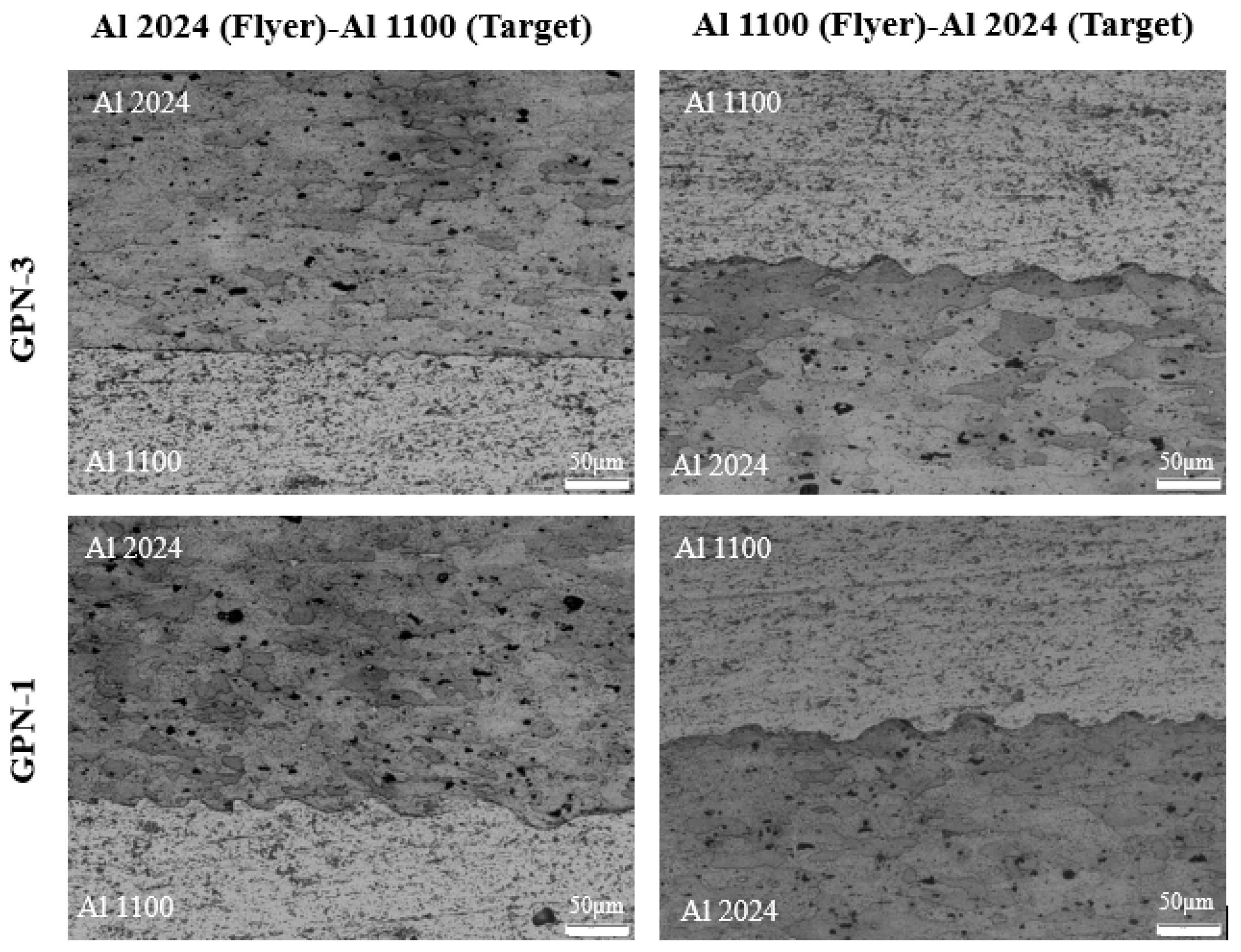
3.3. Microstructure Analysis
4. Case Study to Emphasize the Effect of GPN-3
5. Conclusions
Author Contributions
Funding
Data Availability Statement
Acknowledgments
Conflicts of Interest
References
- Boldsaikhan, E.; Fukada, S.; Fujimoto, M.; Kamimuki, K.; Okada, H.; Duncan, B.; Bui, P.; Yeshiambel, M.; Brown, B.; Handyside, A. Refill Friction Stir Spot Joining Rivet Replacement Technology. In Proceedings of the SAE 2016 Aerospace Manufacturing and Automated Fastening Conference & Exhibition, Bremen, Germany, 4–6 October 2016; SAE International: Warrendale, PA, USA, 2016. [Google Scholar] [CrossRef]
- Boldsaikhan, E.; Fukada, S.; Fujimoto, M.; Kamimuki, K.; Okada, H.; Duncan, B.; Bui, P.; Yeshiambel, M.; Brown, B.; Handyside, A. Refill Friction Stir Spot Joining for Aerospace Aluminum Alloys. In Friction Stir Welding and Processing IX; Hovanski, Y., Mishra, R., Sato, Y., Upadhyay, P., Yan, D., Eds.; Springer International Publishing: Cham, Switzerland, 2017; pp. 237–246. [Google Scholar] [CrossRef]
- Thurston, B.; Lewis, T.; Li, J.; Vivek, A.; Daehn, G. Augmented Laser Impact Welding: A New Process Demonstration in Welding Aluminum Alloy 2024-T3. J. Mater. Eng. Perform. 2023, 33, 12031–12042. [Google Scholar] [CrossRef]
- Daehn, G.S.; Lippold, J.C. Low-Temperature Laser Spot Impact Welding Driven Without Contact. U.S. Patent 8084710B2, 27 December 2011. Available online: https://patents.google.com/patent/US8084710B2/en (accessed on 26 November 2024).
- Jain, A.; Sonia, P.; Kumari, S.; Pushp, P. Study of intermetallic compound (IMC) formed in welding of steel with magnesium: A review. Mater. Today Proc. 2020, 26, 1159–1166. [Google Scholar] [CrossRef]
- Pasang, T.; Pramana, S.S.; Kracum, M.; Misiolek, W.Z.; Aziziderouei, M.; Mizutani, M.; Kamiya, O. Characterisation of Intermetallic Phases in Fusion Welded Commercially Pure Titanium and Stainless Steel 304. Metals 2018, 8, 863. [Google Scholar] [CrossRef]
- Sen, M.; Puri, A.B. Formation of intermetallic compounds (IMCs) in FSW of aluminum and magnesium alloys (Al/Mg alloys)—A review. Mater. Today Commun. 2022, 33, 105017. [Google Scholar] [CrossRef]
- Swift, D.C.; Niemczura, J.G.; Paisley, D.L.; Johnson, R.P.; Luo, S.; Tierney, T.E. Laser-launched flyer plates for shock physics experiments. Rev. Sci. Instrum. 2005, 76, 093907. [Google Scholar] [CrossRef]
- Peck, J. Design Factors in Laser Driven Impact Welding. Master’s Thesis, The Ohio State University, Columbus, OH, USA, 2019. Available online: https://etd.ohiolink.edu/acprod/odb_etd/etd/r/1501/10?clear=10&p10_accession_num=osu1556879640891786 (accessed on 26 November 2024).
- Rubenchik, A.M.; Farmer, J.C.; Hackel, L.; Rankin, J. Methods and System for Controlled Laser-Driven Explosive Bonding. U.S. Patent 9192056, 17 November 2015. Available online: https://labpartnering.org/patents/US9192056 (accessed on 2 January 2016).
- Wang, H.; Taber, G.; Liua, D.; Hansenb, S.; Chowdhuryc, E.; Terry, S.; Lippold, J.C.; Daehn, G.S. Laser impact welding: Design of apparatus and parametric optimization. J. Manuf. Process. 2015, 19, 118–124. [Google Scholar] [CrossRef]
- Thurston, B.P.; Klenosky, D.R.; Misak, H.E.; Vivek, A.; Daehn, G.S. Small-Scale Impact Welding of High-Strength Aluminum Alloys: Process and Properties. J. Mater. Eng. Perform. 2023, 32, 1224–1237. [Google Scholar] [CrossRef]
- Sunny, S.; Gleason, G.; Mathews, R.; Malik, A. Simulation of laser impact welding for dissimilar additively manufactured foils considering influence of inhomogeneous microstructure. Mater. Des. 2021, 198, 109372. [Google Scholar] [CrossRef]
- U.S. Army Materiel Command. Engineering Design Handbook: Explosives Series: Properties of Explosives of Military Interest; U.S. Government Printing Office: Washington, DC, USA, 1971.
- Yoshida, T.; Muranaga, K.; Matsunaga, T.; Tamura, M. Evaluation of explosive properties of organic peroxides with a modified Mk III ballistic mortar. J. Hazard. Mater. 1985, 12, 27–41. [Google Scholar] [CrossRef]
- Liu, W.; Bai, C.; Liu, Q.; Yao, J.; Zhang, C. Effect of metal dust fuel at a low concentration on explosive/air explosion characteristics. Combust. Flame 2020, 221, 41–49. [Google Scholar] [CrossRef]
- Makovky, A.; Lenji, L. Nitromethane physical properties, thermodynamics, kinetics of decomposition, and utilization as fuel. Chem. Rev. 1958, 4, 627–644. [Google Scholar] [CrossRef]
- Bai, C.; Zhang, C.; Liu, W.; Zhao, X.; Sun, B.; Yao, J. Effect of nitromethane on fuel/air explosion characteristics under different ambient conditions. Combust. Flame 2021, 234, 111632. [Google Scholar] [CrossRef]
- Berthe, L.; Fabbro, R.; Peyre, P.; Tollier, L.; Bartnicki, E. Shock waves from a water-confined laser-generated plasma. J. Appl. Phys. 1997, 82, 2826–2832. [Google Scholar] [CrossRef]
- Fabbro, R.; Fournier, J.; Ballard, P.; Devaux, D.; Virmont, J. Physical study of laser-produced plasma in confined geometry. J. Appl. Phys. 1990, 68, 775–784. [Google Scholar] [CrossRef]
- Wang, Q.; Wang, H.; Ran, M.; Tong, Z.; Wang, R.; Zheng, W. The achievement of lap weld and gap control for laser impact welding with water as the confinement layer. J. Manuf. Process. 2023, 95, 105–114. [Google Scholar] [CrossRef]
- Davami, K.; Vaseghi, M.; Brooks, N.; Rowe, R.; Holtham, N.; Southers, T.; Um, T.; Hackel, L. High-velocity laser accelerated deposition (HVLAD): An experimental study. Surf. Coat. Technol. 2023, 466, 129638. [Google Scholar] [CrossRef]
- Fairand, B.; Clauer, A. Laser generated stress waves: Their characteristics and their effects to materials. AIP Conf. Proc. 1979, 50, 27–42. [Google Scholar] [CrossRef]
- Strand, O.T.; Goosman, D.R.; Martinez, C.; Whitworth, T.L.; Kuhlow, W.W. Compact system for high-speed velocimetry using heterodyne techniques. Rev. Sci. Instrum. 2006, 77, 083108. [Google Scholar] [CrossRef]
- Su, Z.; Liang, Z.; Ma, Y.; Du, Y.; Guo, L.; Zhao, B.; Zhou, T.; Wang, X. Influence of surface damage on the optical properties of sapphire and its etching repair method. Ceram. Int. 2024, 50, 10034–10054. [Google Scholar] [CrossRef]
- Chen, Y.-A.; Chien, K.-C.; Chen, I.-T.; Chang, C.-H. Sapphire nanophotonics: Fabrication challenges and optical properties. Micro Nano Eng. 2022, 14, 100115. [Google Scholar] [CrossRef]
- Hoon, S.; Thomas, A.; Linton, P. The Design and Development of a Closed Chamber for the in-situ Quantification of Dryland Soil Carbon Dioxide Fluxes. Geogr. Res. 2009, 47, 71–82. [Google Scholar] [CrossRef]
- Esco Optics, Inc. Sapphire-Grade|Material Data. Available online: https://escooptics.com/pages/sapphire (accessed on 2 January 2025).
- Sielicki, P.W.; Clutter, J.K.; Sumelka, W.; Gajewski, T.; Malendowski, M.; Peksa, P.; Studziński, R. Identification of Aluminium Powder Properties for Modelling Free Air Explosions. Materials 2022, 15, 1294. [Google Scholar] [CrossRef] [PubMed]
- Tanguay, V.; Goroshin, S.; Higgins, A.J.; Zhang, F. Aluminum Particle Combustion in High-Speed Detonation Products. Combust. Sci. Technol. 2009, 181, 670–693. [Google Scholar] [CrossRef]
- Dong, J.; Wang, W.; Wang, X.; Zhou, Q.; Miao, R.; Du, M.; Tan, B.; Wang, Y.; Zhang, T.; Li, Y.; et al. Effects of Nano Aluminum Powder on the Mechanical Sensitivity of RDX-Based Explosives. Nanomaterials 2021, 11, 2182. [Google Scholar] [CrossRef]
- Xu, H.-X.; Li, X.; Zhao, F.-Q.; Pang, W. Review on Application of Nano-metal Powders in Explosive and Propellants. Hanneng Cailiao/Chin. J. Energitic Mater. 2012, 19, 232–239. [Google Scholar] [CrossRef]
- Hui, H. Research on Composite Explosive with Nano-Aluminium. Chin. J. Explos. Propellants 2002. Available online: https://www.semanticscholar.org/paper/Research-on-Composite-Explosive-With-Nano-AluminiumHui/66752ae48831845161f069f0c31a5ab54892ec4b (accessed on 26 November 2024).
- Satonkina, N.P.; Bordzilovsky, S.A.; Danilko, D.A.; Ershov, A.P.; Karakhanov, S.M.; Plastinin, A.V.; Rafeichik, S.I.; Yunoshev, A.S. Influence of aluminum on the characteristics of detonating emulsion explosives. J. Phys. Conf. Ser. 2018, 1128, 012063. [Google Scholar] [CrossRef]
- Zhang, K.; Feng, X.; Zhao, J.; Feng, B.; Feng, X.J.; Wang, X. Effect of Aluminum Powder Content on Air Blast Performance of RDX-Based Explosive Grenade Charge. Adv. Mater. Sci. Eng. 2022, 2022, 1751182. [Google Scholar] [CrossRef]
- Svetovoy, V.B.; Prokaznikov, A.V.; Postnikov, A.V.; Uvarov, I.V.; Palasantzas, G. Explosion of Microbubbles Generated by the Alternating Polarity Water Electrolysis. Energies 2020, 13, 20. [Google Scholar] [CrossRef]
- Chen, J.; Ma, H.; Wang, Y.; Huang, L.; Shen, Z. Effect of hydrogen-storage pressure on the detonation characteristics of emulsion explosives sensitized by glass microballoons. Def. Technol. 2022, 18, 747–754. [Google Scholar] [CrossRef]
- Yamada, M.; Suzuki, Y.; Watanabe, N.; Ishii, K. Effects of bubble gas composition on bubble collapse by an underwater shock wave. Sci. Technol. Energetic Mater. 2022, 83, 88–94. [Google Scholar]
- Shan, F.; Jiao, J.; Wang, H.; Wang, J.; Qi, Y.; Gao, Z.; Chen, P.; Fang, Z.; Pan, X.; He, Y. Influence of overdriven detonation on the energy release of aluminized explosives in underwater explosion. Phys. Fluids 2023, 35, 093305. [Google Scholar] [CrossRef]
- Ishii, K.; Watanabe, N. Shock wave generation by collapse of an explosive bubble in water. Proc. Combust. Inst. 2019, 37, 3653–3660. [Google Scholar] [CrossRef]
- Dada, M.; Popoola, P. Recent advances in joining technologies of aluminum alloys: A review. Discov. Mater. 2024, 4, 86. [Google Scholar] [CrossRef]
- Carvalho, G.H.S.F.L.; Galvão, I.; Mendes, R.; Leal, R.; Moreira, A.; Loureiro, A. The role of physical properties in explosive welding of copper to stainless steel. Def. Technol. 2023, 22, 88–98. [Google Scholar] [CrossRef]


| Power Density (GW/cm2) | Energy (J) | Wavelength (nm) | Pulse Width (nm) | Spot Size (mm) |
|---|---|---|---|---|
| 1.34 | 3.14 | 1064 | 8 | 5.22 |
| Name | Compositions |
|---|---|
| GPN-1 | 1 g Gunpowder + 10 g Nitromethane (Original GPN) |
| GPN-2 | 2 g Gunpowder + 10 g Nitromethane |
| GPN-3 | 1 g Gunpowder + 10 g Nitromethane + 0.1 Micro-air Bubbles |
| GPN-4 | 1 g Gunpowder + 10 g Nitromethane + 0.2 Micro-air Bubbles |
| GPN-5 | 1 g Gunpowder + 10 g Nitromethane + 0.05 Micro-air Bubbles + 0.05 Al Powder |
| GPN-6 | 1 g Gunpowder + 10 g Nitromethane + 0.1 Micro-air Bubbles + 0.05 Al Powder |
| GPN-7 | 1 g Gunpowder + 10 g Nitromethane + 0.1 Micro-air Bubbles + 0.1 Al Powder |
| Properties | Density (g/cm3) | Light Transmission Range (µm) | Refractive Index | Hardness | ||
|---|---|---|---|---|---|---|
| Material | (Moh’s) | Knoop | ||||
| Borosilicate Glass | 2.2–2.6 | 0.3–2.5 | 1.47–1.5 | 5.5 | 418 | |
| Sapphire | 4 | 0.17–5.5 | 1.8 | 9 | 2000 | |
| Material (0.5 mm Thick) | GPN-1 (1 g G.P.+ 10 g Nit.) | GPN-II (1 g G.P. + 10 g Nit. + 0.5 g Al Powder) | GPN-2 (2 g G.P. + 10 g Nit.) | |||
|---|---|---|---|---|---|---|
| Sapphire | Water | Sapphire | Water | Sapphire | Water | |
| Al 2024 | 540 | 230 | 486 | 191 | 529 | 226 |
| Al 6061 | 595 | 274 | 513 | 239 | 556 | 221 |
| Material (0.5 mm) | GPN Thickness (mm) | GPN-1 (1 g GP + 10 g Nit.) | GPN-3 (1 g GP + 10 g Nit. + 0.1 g Micro. Bubbles) | GPN-4 (1 g GP + 10 g Nit. + 0.2 g Micro. Bubbles) | GPN-5 (1 g GP + 10 g Nit. + 0.05 g Micro. Bubbles + 0.05 Al Powder) | GPN-6 (1 g GP + 10 g Nit. + 0.1 g Micro. Bubbles + 0.05 g Al Powder) | GPN-7 (1 g GP + 10 g Nit. + 0.1 g Micro. Bubbles + 0.1 g Al Powder) | ||||||||||||
|---|---|---|---|---|---|---|---|---|---|---|---|---|---|---|---|---|---|---|---|
| Glass | Sapphire | Water | Glass | Sapphire | Water | Glass | Sapphire | Water | Glass | Sapphire | Water | Glass | Sapphire | Water | Glass | Sapphire | Water | ||
| Flyer Velocity (m/s) | |||||||||||||||||||
| Al 2024 | 0.2 | 604 | 545 | 207 | 629 | 611 | 346 | 592 | 365 | 217 | 593 | 561 | 244 | 577 | 565 | 310 | 590 | 570 | 342 |
| 0.37 | 720 | 645 | 219 | 755 | 704 | 360 | 643 | 486 | 262 | 711 | 700 | 292 | 707 | 677 | 331 | 741 | 704 | 349 | |
| Al 6061 | 0.2 | 700 | 539 | 267 | 814 | 777 | 399 | 704 | 470 | 248 | 728 | 720 | 301 | 604 | 590 | 351 | 695 | 662 | 372 |
| 0.37 | 843 | 691 | 280 | 884 | 814 | 410 | 752 | 593 | 299 | 789 | 773 | 340 | 793 | 791 | 394 | 859 | 793 | 376 | |
| Material (Thickness) | Ablative Layer | Confinement Layer | Energy (J) | Setup | Spot Size (mm) | Note |
|---|---|---|---|---|---|---|
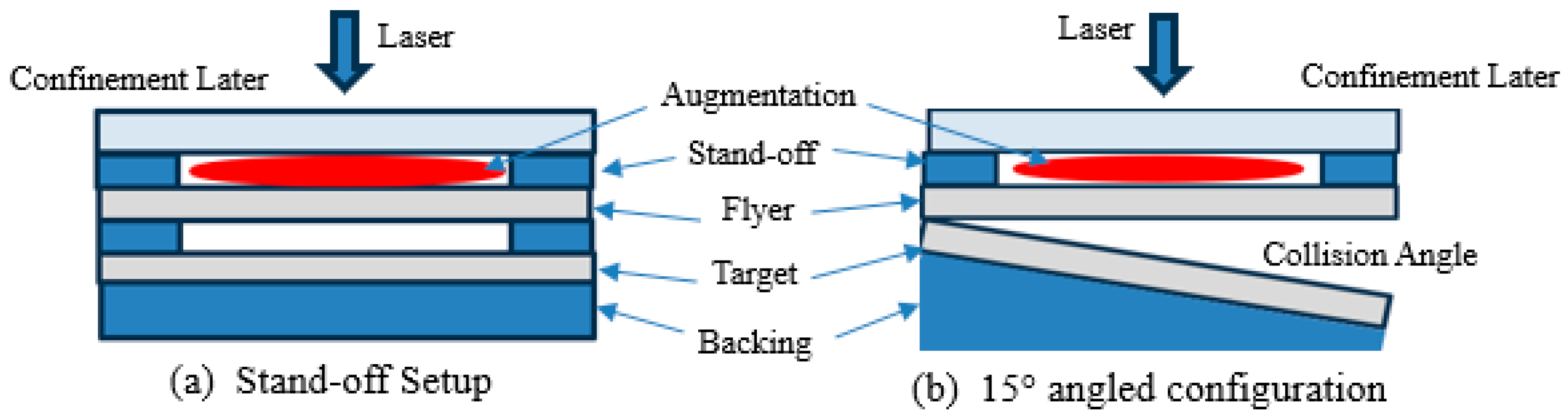
| 2024/1100 (1 mm/1 mm) | GPN-3 | Sapphire and Glass | 3 | Stand-off (0.5 mm) | 5.22 | Successful Welded Joints |
| 6061/1100 (1 mm/1 mm) | ||||||
| 2024/1100 (1 mm/1 mm) | Angle 15° | |||||
| 6061/1100 (1 mm/1 mm) |
Disclaimer/Publisher’s Note: The statements, opinions and data contained in all publications are solely those of the individual author(s) and contributor(s) and not of MDPI and/or the editor(s). MDPI and/or the editor(s) disclaim responsibility for any injury to people or property resulting from any ideas, methods, instructions or products referred to in the content. |
© 2025 by the authors. Licensee MDPI, Basel, Switzerland. This article is an open access article distributed under the terms and conditions of the Creative Commons Attribution (CC BY) license (https://creativecommons.org/licenses/by/4.0/).
Share and Cite
Abdelmaola, M.; Thurston, B.; Panton, B.; Vivek, A.; Daehn, G. Influence of Augmentation Compositions and Confinement Layers on Flyer Velocity in Laser Impact Welding. Metals 2025, 15, 190. https://doi.org/10.3390/met15020190
Abdelmaola M, Thurston B, Panton B, Vivek A, Daehn G. Influence of Augmentation Compositions and Confinement Layers on Flyer Velocity in Laser Impact Welding. Metals. 2025; 15(2):190. https://doi.org/10.3390/met15020190
Chicago/Turabian StyleAbdelmaola, Mohammed, Brian Thurston, Boyd Panton, Anupam Vivek, and Glenn Daehn. 2025. "Influence of Augmentation Compositions and Confinement Layers on Flyer Velocity in Laser Impact Welding" Metals 15, no. 2: 190. https://doi.org/10.3390/met15020190
APA StyleAbdelmaola, M., Thurston, B., Panton, B., Vivek, A., & Daehn, G. (2025). Influence of Augmentation Compositions and Confinement Layers on Flyer Velocity in Laser Impact Welding. Metals, 15(2), 190. https://doi.org/10.3390/met15020190