Article

Use of Sn91Zn9 Lead-Free Solder in Resistance Element Soldering Technology

Institute of Technologies and Materials, Faculty of Mechanical Engineering, Slovak University of Technology in Bratislava, Námestie Slobody 17, 812 31 Bratislava, Slovakia
*
Author to whom correspondence should be addressed.
Metals 2025, 15(3), 306; https://doi.org/10.3390/met15030306
Submission received: 10 February 2025 / Revised: 5 March 2025 / Accepted: 7 March 2025 / Published: 11 March 2025

Abstract

:
Resistance Element Soldering (RES) is one of the new methods of joining dissimilar materials by resistance heating using an element. Sn60Pb40 solder, which has been used for decades in tin smithing and the electrical industry, has already been tested for joining galvanized steel sheet with thermoplastic using RES. However, legal restrictions are currently moving towards prohibiting the use of lead in mass production. For this reason, the possibility of replacing Sn60Pb40 solder with Sn91Zn9 lead-free solder was verified. The results showed that with an appropriate choice of flux and resistance heating conditions, it is possible to replace Sn60Pb40 solder with Sn91Zn9 solder when joining galvanized steel sheet with thermoplastic using RES. With a suitable heat input during soldering, good conditions were achieved for wetting the base material with molten solder with a sufficient volume of remelted solder in the core of the Cu/Sn91Zn9 bimetallic element. The strength of the soldered joint made at a heat input of 901 J was measured at the level of 94% of the strength of Sn91Zn9 solder.

Graphical Abstract

1. Introduction

In the paper [1], the Resistance Element Soldering (RES) method of joining dissimilar materials was presented, which is based on the principle of Resistance Element Welding (REW) [2]. RES uses a bimetallic element, which consists of a shell made of sufficiently strong metal and a core of solder, to join dissimilar materials at a low resistance heating temperature. The shell provides a form-fit connection of the overlap materials, while the solder metallurgically joins the element with the lower joined material. The results published in the initial study [1] were obtained in the evaluation of RES joints between galvanized steel sheet and PMMA thermoplastic using a Cu/Sn60Pb40 bimetallic element (the shell was made of Cu, and the core of Sn60Pb40). Sn60Pb40 solder has been used for several decades for the soldering of galvanized steel sheet, e.g., in tin smithing. It is characterized by a low liquidus temperature (190 °C) and a short freezing range (7 °C) [3]. Currently, however, the global trend is to limit, from the point of view of environmental burden, the use of lead in mass production. In Europe and other countries of the world, relevant legislation has already been adopted for this purpose.
In January 2003, the European Parliament and Council issued directives on effects and restrictions regarding the use of certain hazardous substances [4,5,6,7]. Other countries of the world approach restrictions on the use of hazardous substances differently. Japan has no direct restriction of hazardous substances legislation. In April 2007, South Korea issued the act on resource circulation of electrical and electronic equipment and vehicles [8]. China has compiled a list of products that must be labeled with information about the presence of hazardous substances [9]. Among all US states, only California adopted the electronic waste recycling act of 2003 (EWRA). Other US states are still considering whether to adopt similar laws, although there are several states that have already prohibited mercury [10]. Based on the aforementioned directives, manufacturers in the EU are also required to replace tin–lead solders with lead-free solders. Although the dominant field in the use of lead-free solders is the electrical industry [11], there is an effort to replace lead in other products as well, mainly for reasons of recycling.
In this study, Sn60Pb40 solder in bimetallic elements for RES joints [1] was replaced by Sn91Zn9 lead-free solder. Zinc-based solders are currently used, for example, in the production of heat exchangers made of aluminum, copper or brass (automotive industry) due to their corrosion resistance. The content of Zn in alloys limits galvanic corrosion of base materials in an aggressive environment (important when soldering aluminum alloys) [3]. The results obtained during the analysis of the properties of the joints between galvanized steel sheet and thermoplastic using the Cu/Sn91Zn9 bimetallic element were compared with the properties of the joints made using the Cu/Sn60Pb40 bimetallic element [1].

2. Materials and Methods

To assess the suitability of Sn91Zn9 lead-free solder for bimetallic elements for RES of galvanized steel sheet and plastic, several test samples were made (Figure 1). The materials used for the production of experimental joints were the same as in the previous study [1]—HX220BD-100MBO galvanized steel sheet with a thickness of 0.8 mm (U.S. Steel Košice, Slovakia) and QUINN XT (PMMA) thermoplastic sheet with a thickness of 2 mm (KHplexi, Praha, Czechia). The only difference was that a bimetallic element with a new core material was used, with Sn60Pb40 solder replaced by Sn91Zn9 lead-free solder. The representative chemical composition and mechanical properties of the materials used are listed in Table 1, Table 2, Table 3, Table 4 and Table 5.
Sn91Zn9 lead-free solder is characterized in several publications as a suitable replacement for the Sn60Pb40 solder used so far [12,13]. Sn91Zn9 solder has a liquidus temperature (198.5 °C) close to the liquidus temperature of Sn60Pb40 solder (190 °C) and possesses good mechanical properties [3,14]. Its wider use in the electrical industry is hindered by the lower wettability of the Cu substrate, caused by higher surface tension and the susceptibility of Zn to oxidation [15,16].
The measured values of the mechanical properties of the Sn91Zn9 solder used correspond to data published in [17].
Table 1. Chemical composition of HX220BD-100MBO steel data from Ref. [18].
MaterialC
(wt.%)
Si
(w.%)
Mn
(wt.%)
P
(wt.%)
S
(w.%)
Nb
(wt.%)
Ti
(wt.%)
Al
(wt.%)
HX220BD-100MBO0.10.50.70.080.0250.090.120.1
Table 2. Mechanical properties of HX220BD-100MBO steel data from Ref. [18].
MaterialRP0.2 (MPa)Rm (MPa)A80 (%)
HX220BD-100MBO220–280320–40032
Table 3. Properties of QUINN XT (PMMA) thermoplastic data from Ref. [19].
Tensile Strength ISO 527-2 [20] (MPa)Flexural Strength ISO 178 (MPa)Elongation at Break ISO 527-2 (%)Impact Strength Charpy Unnotched ISO 179-1 (KJ/m2)Vicat Temperature (B50) * ISO 306 (°C)Maximal Temperature for Short Term Use (°C)Degradation Temperature (°C)
7011541710590>280
* Pre-treatment 16 h at 80 °C.
Table 4. Chemical composition of Sn91Zn9 solder data from Ref. [21].
MaterialSnPbCuZnAgSbBiCd
(wt.%)(wt.%)(wt.%)(wt.%)(wt.%)(wt.%)(wt.%)(wt.%)
Sn91Zn9910.10.058.5–9.50.10.10.10.002
Table 5. Mechanical properties of the materials in the bimetallic element.
MaterialDensity
(g/cm3)
Yield Strength Re (MPa)Ultimate Tensile Strength Rm (MPa)Elongation at Break A (%)
Cu8.9655.523843.7
Sn91Zn97.241.558.852.2
Figure 2 shows the shape, dimensions and overall view of the Cu/Sn91Zn9 bimetallic element. The element consists of a shell made of a Cu tube (outer diameter 6 mm, wall thickness 0.5 mm) and a core made of Sn91Zn9 lead-free solder, which is an almost eutectic alloy (the Sn–Zn eutectic alloy contains 8.8 wt.% Zn) [22]. The production method of bimetallic elements is detailed in the paper [23].
Before resistance soldering, the bimetallic element was inserted into a pre-drilled hole in PMMA thermoplastic sheet (Figure 1). The galvanized steel sheet was cleaned with acetone and SF-601 liquid flux was applied to the cleaned surface [24].
An ARO XMA 26kVA, AC 50 Hz portable spot-welding gun (ARO S.A.S., Chateau-du-Loir, France) with a ULB 1.4 universal control system (VTS Electro s.r.o., Bratislava, Slovakia) was used for resistance soldering. The welding gun was equipped with Cu–Cr electrodes with flat (FD type) and semi-round (FB type) contact surfaces. A 16 mm diameter FD-type electrode was used from the top to ensure uniform pressure on the element head. An FB type electrode was used from the bottom of the galvanized sheet. Process parameters (electric current—I, voltage—U, and soldering time—t) were monitored by a Miyachi Weld Checker MM-356 B measuring device (Miyachi Technos Corporation, Arakawaku, Tokyo, Japan).
The prepared samples were subjected to evaluation of their mechanical properties by a tensile test to determine their ultimate tensile strength according to the EN ISO 6892-1 standard [25]. An Instron 1195 universal testing machine (Instron Limited, Buckinghamshire, UK) was used.
Structural analysis of the joints was performed on cross-sections of samples that were prepared metallographically. A JEOL JSM-IT300 (JEOL Ltd., Akishima, Tokyo 196-8558, Japan) scanning electron microscope (SEM) with energy-dispersive spectroscopy (EDS) was used for microstructure identification and chemical analysis of created phases.
The effect of the following was investigated on experimental RES joints using Cu/Sn91Zn9 bimetallic elements between galvanized steel sheet and thermoplastic sheet:
-
amount of heat on the volume of remelted solder in the bimetallic elements;
-
amount of heat on the appearance of the joined materials;
-
process parameters on the strength of the joints;
-
process parameters on the structure of the joints and the fracture surfaces.
The achieved results were compared with the data obtained during RES using Cu/Sn60Pb40 bimetallic elements published in the paper [1].

3. Results and Discussion

Table 6 shows the parameters of resistance heating during RES of galvanized steel sheet with thermoplastic using Cu/Sn91Zn9 bimetallic elements. During the production of test samples, a current (I) of 6.07 to 6.25 kA was used with a voltage (U) of 0.45 to 0.49 V. A soldering time (t) of 0.1 to 0.4 s was used. This created the conditions for heating the joint with a theoretical (calculated) heat input (Q) of 291 to 1125 J.
The general view of the prepared test samples from the front and back sides is shown in Figure 3 and Figure 4, the details of the joints are in Figure 5. When using elements with a core of Sn91Zn9 lead-free solder, as well as when using Cu/Sn60Pb40 elements [1], we noticed significant spattering of the solder from the element at maximum heat input during resistance heating with a soldering time of 0.4 s (Table 6, Figure 3d and Figure 5c). For this reason, the maximum heat input (at a soldering time of 0.4 s) was no longer used for the production of test samples.
At soldering times of 0.1, 0.2, and 0.3 s, no or only minimal spatter was observed between galvanized steel sheet and thermoplastic sheet (Figure 3a–c and Figure 5a,b). As with the use of Sn60Pb40 solder, in this case we also did not notice any thermal disruption of the protective Zn coating on the galvanized steel sheet at the RES joint location (Figure 5d).
A general view of the cross-section of a soldered joint (between galvanized steel sheet and bimetallic element) and details of selected locations of the solder/steel sheet interface are shown in Figure 6. The general view of the soldered joint made (Figure 6a), as well as details of selected joint locations (Figure 6b,c), document good wetting of the base material (galvanized steel sheet) with molten solder at a resistance heating time of 0.3 s without the appearance of defects at the solder/steel sheet interface. Defects (pores and cracks) occurred in the core of the bimetallic element. The cause of the formation of pores was probably insufficient degassing of the remelted solder during resistance heating (effect of evaporating flux). The rare occurrence of cracks is related to the creation of radial stresses and deformations during cooling of the remelted solder during joint production.
Due to the almost eutectic composition of the solder, the microstructure is formed by a mechanical mixture of β-Sn (white gray) and α-Zn phases (dark gray) in Figure 7a. The structure that is determined corresponds to the Sn–Zn binary phase diagram [22].
The detail of the interface between the galvanized steel sheet and the Sn91Zn9 solder, supplemented by a line analysis of the distribution of elements, is shown in Figure 8. As with the use of Sn60Pb40 solder [1], dissolution of the zinc protective coating of the steel sheet by molten solder was also observed in the transition area of the joint with Sn91Zn9 solder. In this case, the thickness of the transition area was up to 1 μm.
Since bimetallic, semi-finished products for the production of elements were made by centrifugal casting, during which Cu tubes preheated to 220 °C and inserted into a hot mold (120 °C) were filled with molten solder at a temperature of 220 °C at a mold rotation of 300 min−1, the phases of Zn in the as-cast structure (Figure 9) ranged in size from 3.1 to 46.6 μm due to the relatively long solidification time. This was investigated by image analysis of the microstructure (Figure 9) made from a cross-section of the bimetallic semi-finished products.
The short soldering time (0.1 to 0.4 s) and high cooling rates were the cause of the changes in size of Zn phases in the remelted solder of the element (Figure 10). The size of Zn phases in the structure of remelted solder was significantly smaller than in the as-cast (unfused) structures of bimetallic semi-finished products and reached values from 1.4 to 7.2 μm. The aforementioned change in structure was thus the primary factor for determining the solid/liquid interface of the solder due to resistance heating in the core of the bimetallic element. The amount of remelted Sn91Zn9 solder in the core of the elements is shown in Figure 11 (see the red line). The interface between the unfused and remelted solder was determined based on microscopic observations of cross-sections of the samples. Details of the interface are shown in Figure 11b. The asymmetric distribution of the volume of remelted solder is due to imperfections in the positioning of the electrodes during the manual production of the samples. The portion of remelted solder and the position of the solid/liquid interface were evaluated from the cross-sections of the joints based on the analysis of the core structure.
A comparison of the effect of process parameters on the volume of remelted solder in the Cu/Sn91Zn9 bimetallic element is in Table 7. The increase in the volume of remelted solder from 11% (at a soldering time of 0.1 s) to 52% (at a soldering time of 0.3 s) corresponds to an increase in the heat input to the soldered joint from 291 to 901 J.
The results for the tensile strength of the joints made using the Cu/Sn91Zn9 bimetallic elements were compared with the tensile strength of the joints in which Sn60Pb40 solder was used in the core of the elements [1].
The results of testing the first series of samples showed that the tensile strength of the RES joints between the galvanized steel sheet and PMMA thermoplastic sheet exceeded the tensile strength of the plastic. The test samples were always damaged by ruptures in the plastic in the area of the pre-drilled hole for the element (Figure 12). In order to determine the real strength of the soldered joints, another series of test samples was made in which PMMA thermoplastic was replaced by AW-1050A wrought aluminum alloy. The higher strength of the aluminum alloy compared to the plastic was supposed to ensure the occurrence of ruptures during the tensile tests of the soldered joints. The chemical composition and mechanical properties of AW-1050A alloy are shown in Table 8 and Table 9.
Figure 13 shows samples of RES joints between galvanized steel sheet and aluminum alloy sheet after tensile testing. It is clear from the pictures that all the samples ruptured at the soldered joint during the tensile tests. This fact allowed us to evaluate the influence of soldering conditions on the strength and structure of joints.
The achieved tensile strength values (Table 10) show that the strength of the joints made with the Cu/Sn91Zn9 elements are significantly affected by the heat input introduced into the joint during soldering. At the shortest soldering time of 0.1 s (Q = 291 J), the average strength of the joints was 29.66 MPa, which represents approximately 50% of the strength of the Sn91Zn9 solder (Table 5). By extending the soldering time to 0.3 s (Q = 901 J), the average strength of the joints increased to 55.14 MPa, which already represents approximately 94% of the strength of the Sn91Zn9 solder (Table 5).
Comparison of the ultimate tensile strength of RES joints made with bimetallic elements, for the production of which Sn91Zn9 and Sn60Pb40 [1] solders were used, is shown in Figure 14. In both cases, a positive effect of the increase in heat input during soldering on the joint strength was noted. When using a soldering time of 0.3 s, the strength of the joints reached values close to the strength of the solder used—with Sn91Zn9 lead-free solder, the joint strength was at the level of 94% of the solder strength, with Sn60Pb40 solder at the level of 87% of the solder strength [1]. In the case of both types of solders, the further increase in heat input has a negative effect on the properties of the joint—with a soldering time of 0.4 s, intense spattering of the solder into the gap between the joined materials occurred in all samples (see Figure 5c in [1]), which negatively affected the quality of the joint. In addition, the increased amount of heat in the joint can cause local thermal or thermal-oxidative decomposition of plastic.
A general view of the fracture surfaces of the joints made at different soldering times (heat input) from the side of the galvanized steel sheet is shown in Figure 15. Pictures document a good wetting of the base material (galvanized steel sheet) by the molten solder Sn91Zn9. As can be seen, the extension of the soldering time from 0.1 to 0.2 s caused local spattering of the solder (Figure 15b). At a soldering time of 0.3 s, spattering occasionally occurred around the entire circumference of the Cu shell of the element (Figure 15c). Just as in resistance spot welding, so also in soldering, spatter occurs at the moment when the balance between the build-up of energy accumulated in the molten metal and the ability of the surrounding material to withstand internal pressure is broken [28].
Figure 16a shows the fracture surface from the side of the bimetallic element. Detail in Figure 16b shows the ductile fracture of the soldered joint. The maps of the distribution of elements in the fracture surface (Figure 16d,e) show that the fracture passed through the solder (a region with dominant representation of Sn).
By dissolving the zinc coating of the steel sheet with molten Sn91Zn9 solder, the total portion of Zn in the solder at the joint increased from 9 to 28% (Figure 16c). It was also alloyed with aluminum (Figure 8) because Al is an important element in galvanizing baths. Its presence affects the formation of an Fe–Al inhibitor layer at the interface (Fe2Al5), which slows down the growth of Fe–Zn intermetallic phases [29,30].
Tests so far have shown that a higher portion of Zn (over 20%) in the Sn–Zn alloy does not have a significant effect on tensile strength. On the other hand, the ductility of alloys decreases with decreasing Sn content [31]. According to the published results, a small amount of Al (0.5%) in the Sn91Zn9 alloy reduces the size of the Zn phases and increases tensile strength and shear strength. However, the Al content has a negative effect on the ductility of the alloy [32,33]. In both cases, by changing the chemical composition of the solder in the diffusion area (Figure 8), a decrease in the deformation capabilities of the soldered joint can be expected, but this has not yet been confirmed experimentally.

4. Conclusions

The aim of this work is to evaluate some properties of RES joints for galvanized steel sheet and plastic sheet produced using the Cu/Sn91Zn9 bimetallic element. For this purpose, test samples of joints between HX220BD-100MBO galvanized steel sheet and QUINN XT (PMMA) thermoplastic sheet or AW-1050A aluminum alloy sheet (only to evaluate the strength of the soldered joints) were prepared. The results were additionally compared with the data obtained when using Sn60Pb40 solder in the bimetallic element, published in the work [1]. Based on the results achieved, it is possible to state the following:
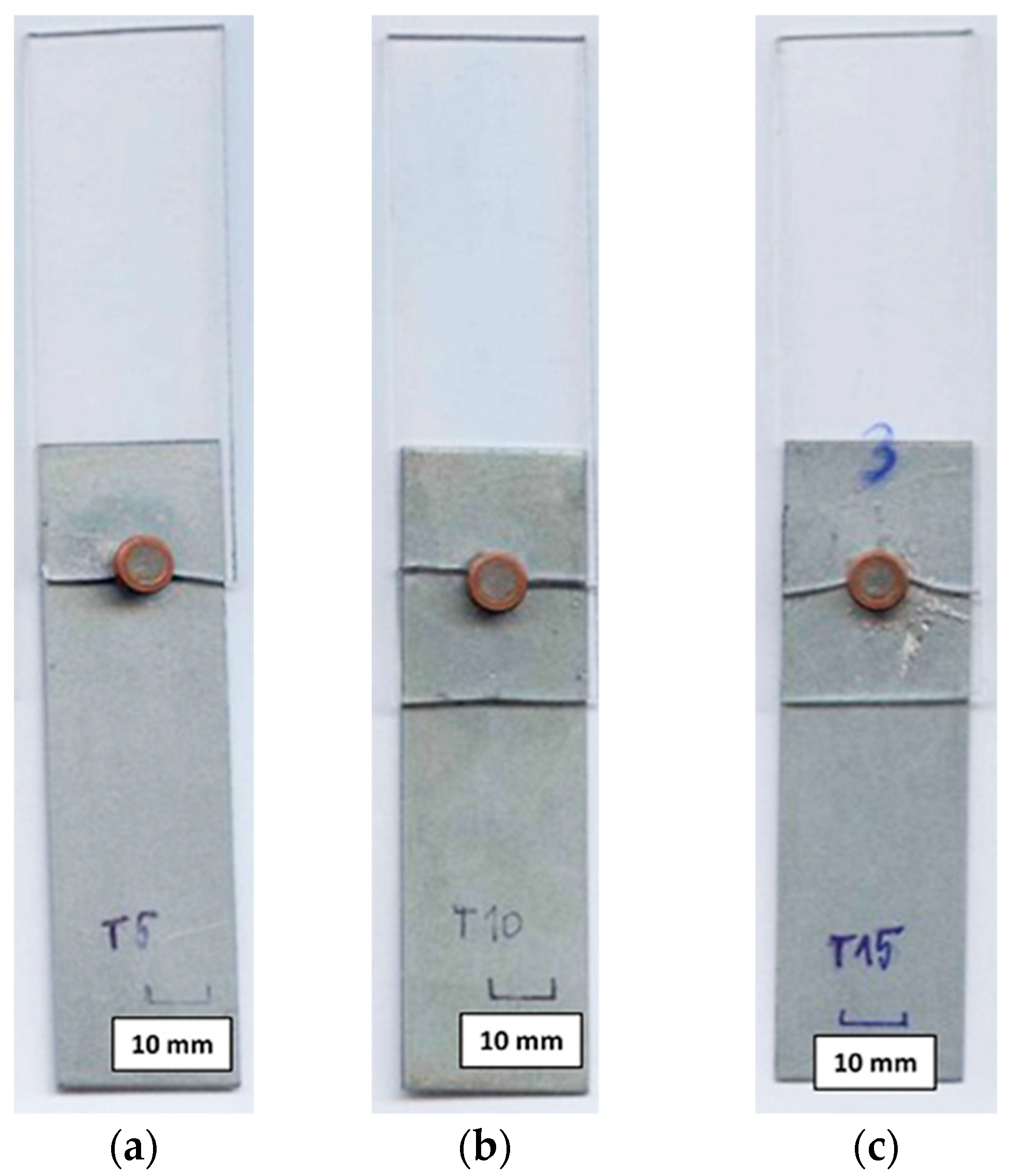
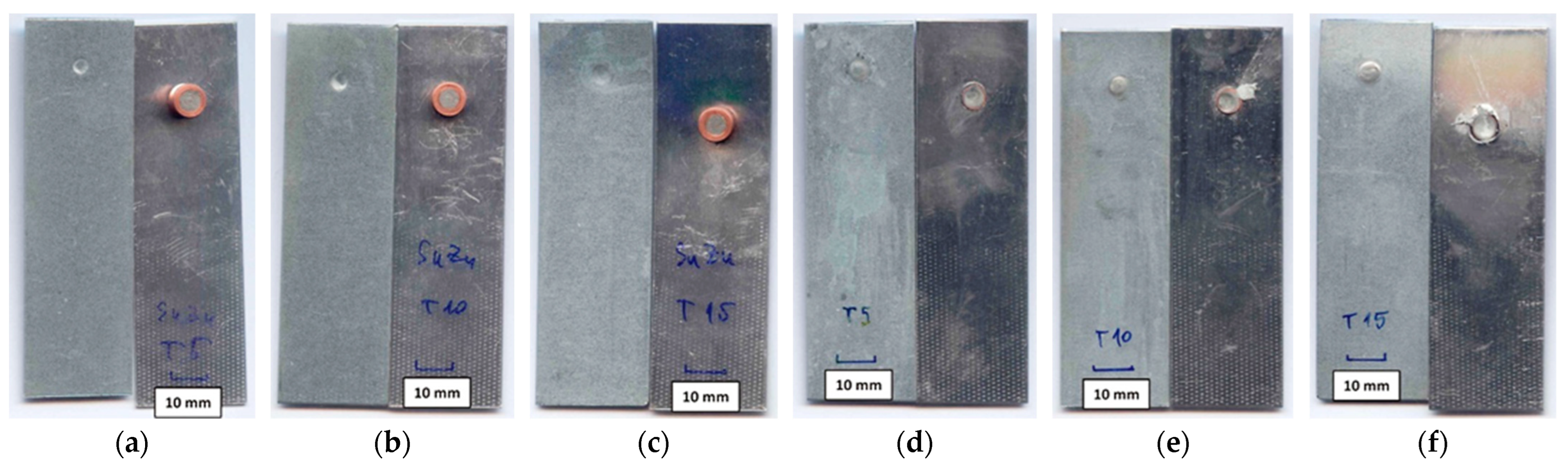
  • The soldering time (heat input) has a significant effect on the spattering of Sn91Zn9 solder around the joint. At soldering times of 0.1 to 0.3 s (Q = 291 to 901 J), spatter appeared only occasionally. At the heating time t = 0.4 s, the solder spatter was already a permanent manifestation of the heating of the bimetallic element.
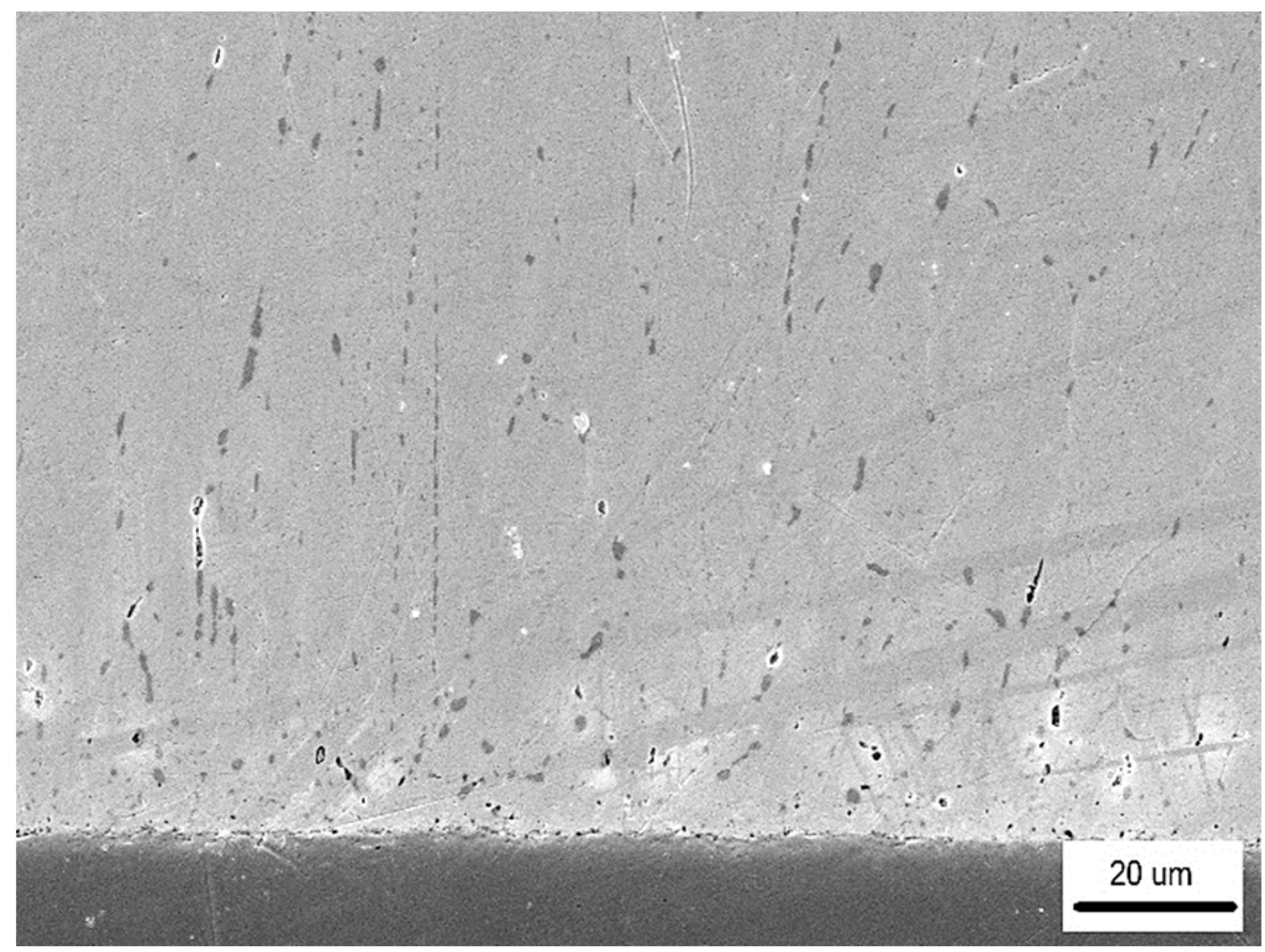
  • The flux used as well as the soldering conditions (process parameters) ensured good wetting of the base material with molten solder without the appearance of cracks or other imperfections at the solder/steel sheet interface.
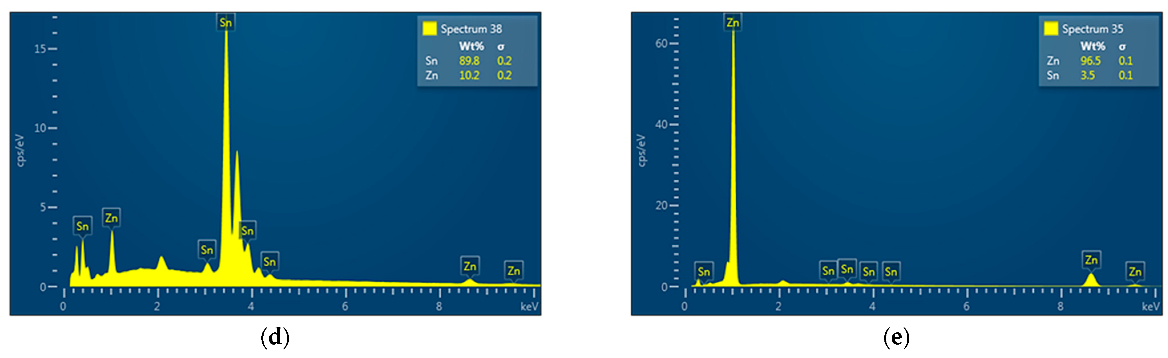
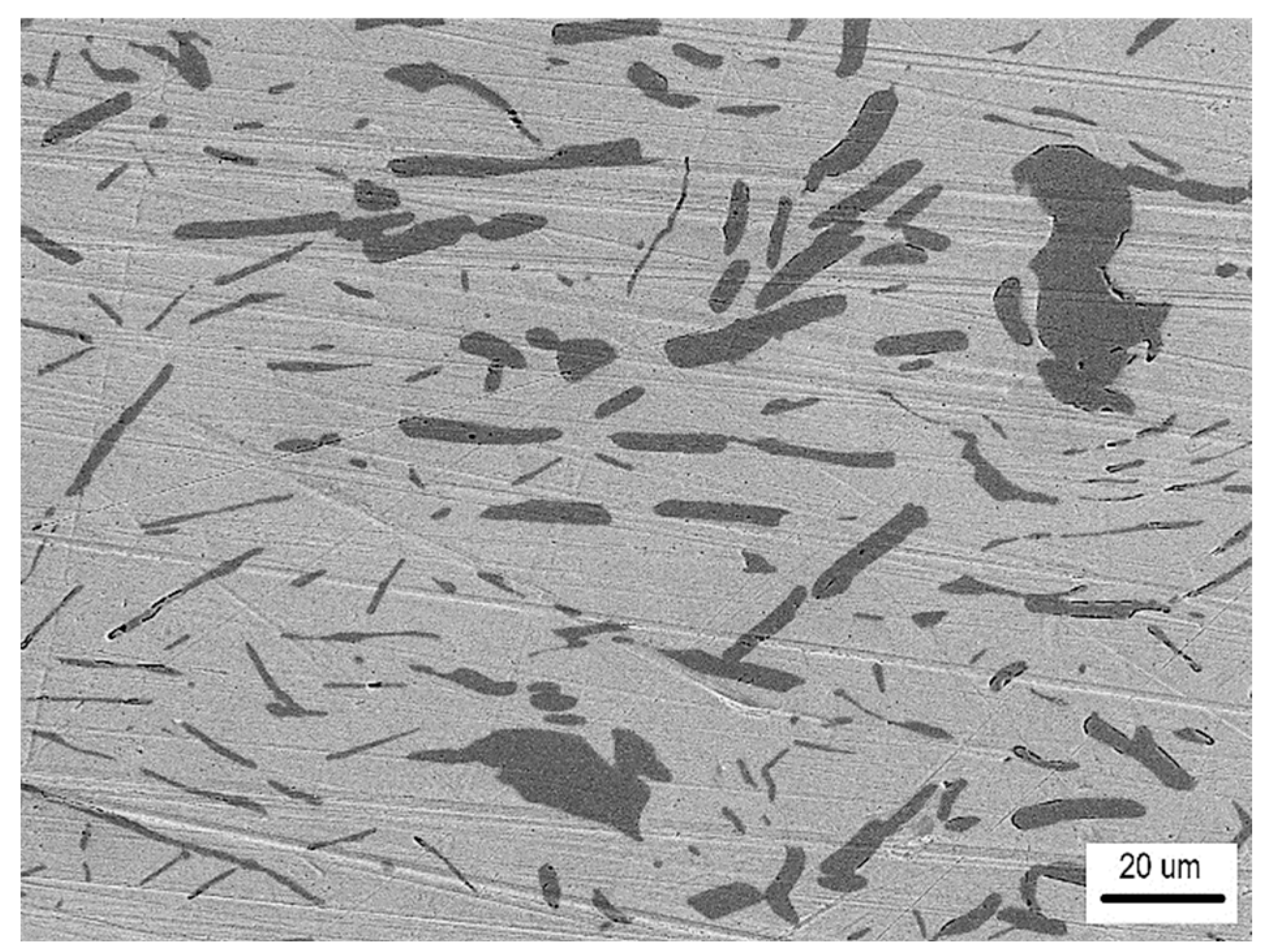
  • The detected Sn91Zn9 solder structure in the core of the bimetallic element corresponded to the Sn–Zn equilibrium binary diagram. Due to the almost eutectic composition, the structure of the solder was formed by a mechanical mixture of solid solutions α-Zn and β-Sn. The difference between the structure of the solder before and after remelting under resistance heating was in the grain size. In the non-remelted (as-cast and unfused) core volume of the bimetallic element, the zinc phases were 3.1 to 46.6 µm in size, in the remelted core volume they were 1.4 to 7.2 µm in size. Differences in grain size were caused by different temperature cycles during the production of semi-finished products for bimetallic elements by centrifugal casting and during soldering. The different grain sizes enabled a relatively accurate evaluation of the influence of the amount of heat generated during soldering on the volume of remelted solder in the core of the bimetallic element. It ranged from 11.2% (of the total core volume) at a soldering time of 0.1 s (Q = 291 J) up to 52.1% at a soldering time of 0.3 s (Q = 901 J).
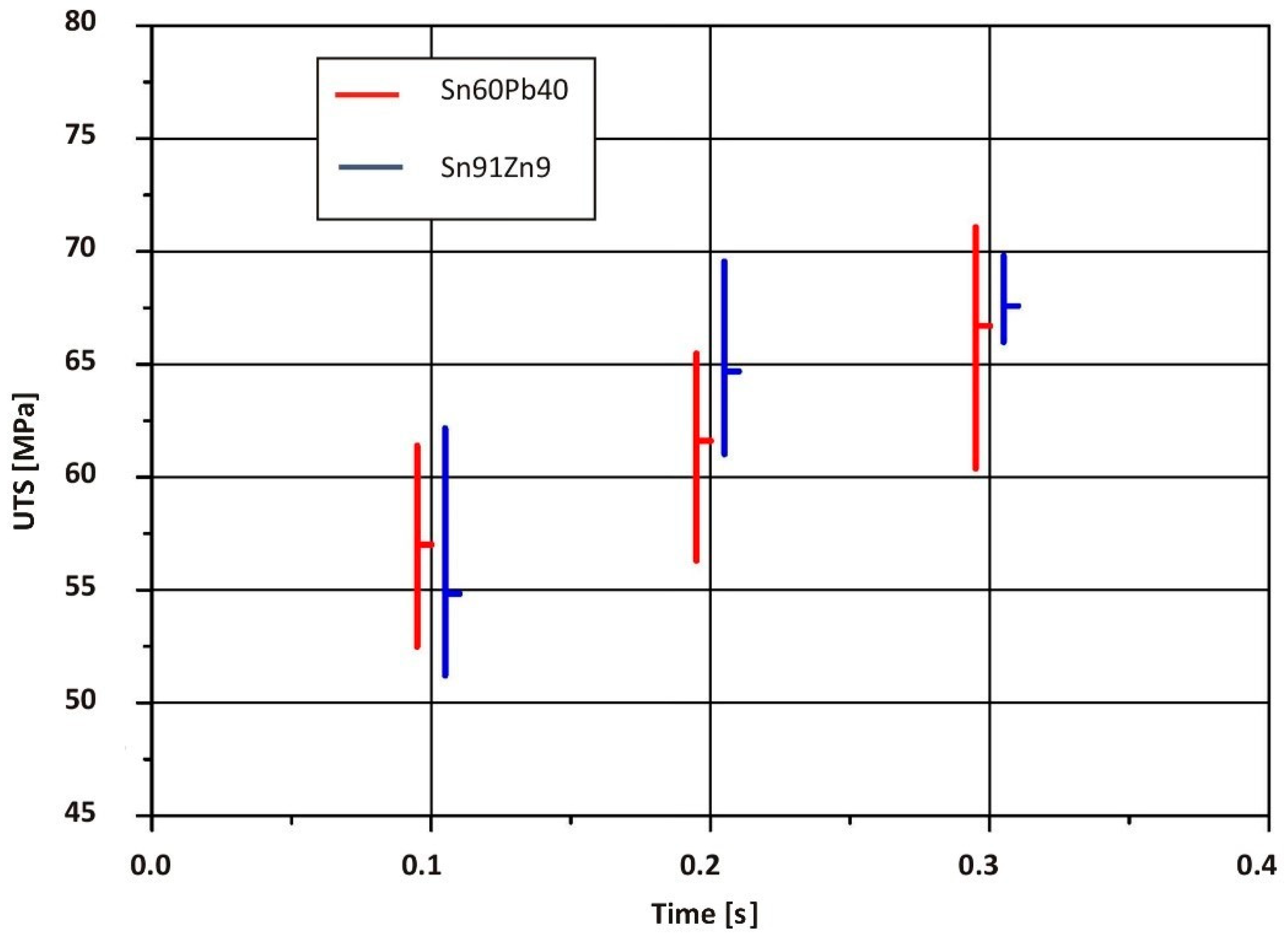
  • Due to the solder joint being greater in strength than the of the PMMA thermoplastic sheet, the plastic on the tensile test samples was replaced with AW-1050A aluminum alloy sheet. The results showed that the strength of RES joints is primarily determined by heat input during soldering. The highest average ultimate tensile strength of joints made with a Cu/Sn91Zn9 bimetallic element (55.14 MPa) was obtained at a soldering time of 0.3 s (Q = 901 J). The obtained value in this case represented 94% of the Sn91Zn9 solder strength. After comparing the average ultimate tensile strength of RES joints, which were made using Cu/Sn91Zn9 and Cu/Sn60Pb40 bimetallic elements, we can conclude that the strength of the joints when using Sn91Zn9 lead-free solder was slightly higher. When Sn60Pb40 solder was used, the maximum joint strength was 53.4 MPa, which represented 87% of the solder strength [1].
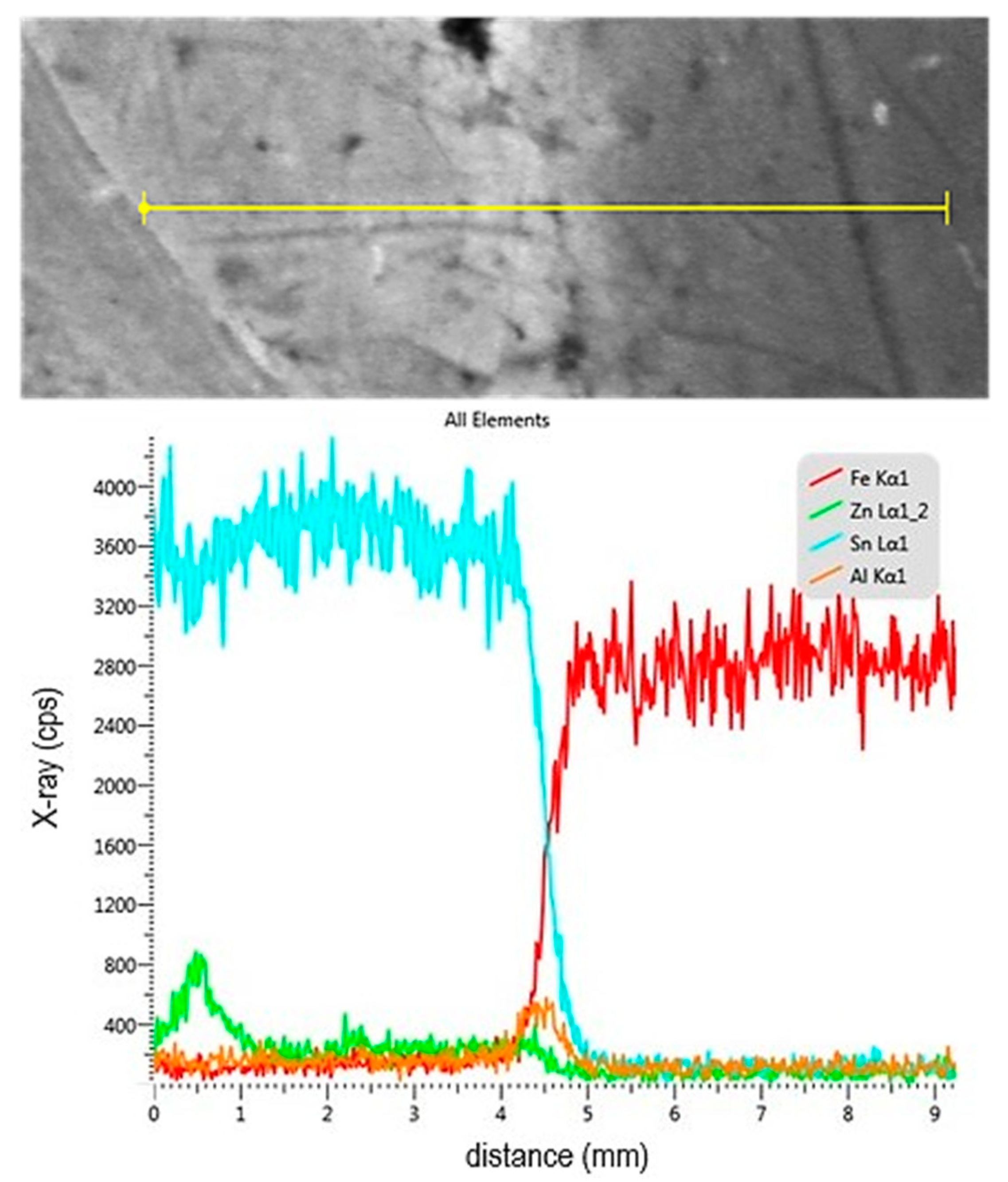
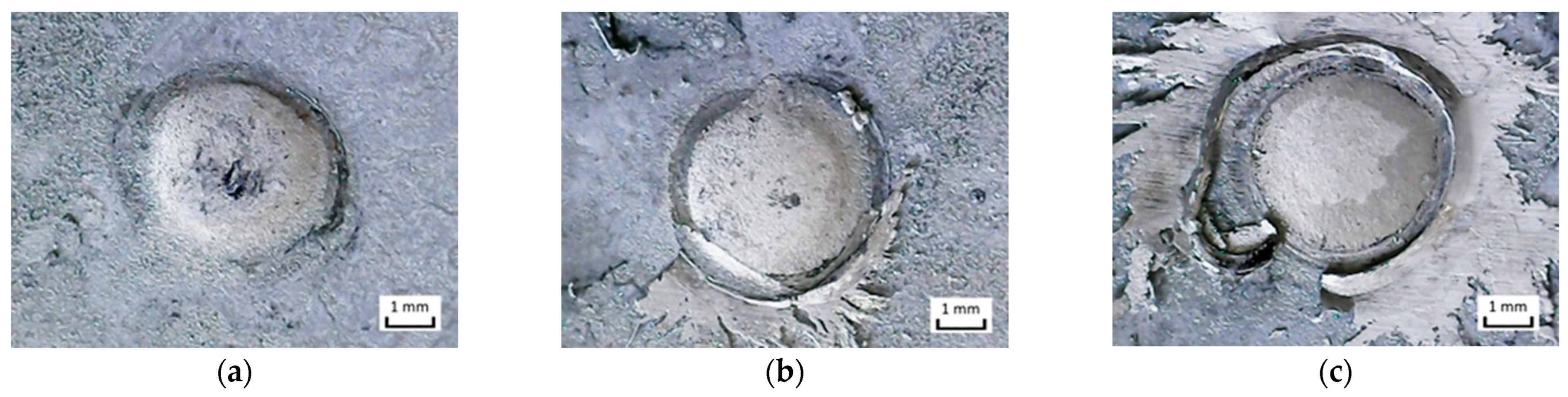
  • The topography of the fracture surface of the Sn91Zn9 solder showed the character of a ductile fracture. By dissolving the zinc coating of the steel sheet with liquid solder, the diffusion zone of the solder was saturated with zinc and aluminum because aluminum is an important element in galvanizing baths. However, the diffusion area was very narrow, reaching a thickness of about 1 µm. Zinc saturation was significant, and the portion of the element increased from 9 to 28%. By increasing the content of Zn in the diffusion area of the solder, a decrease in the deformation capabilities of the Sn91Zn9 solder can be expected.
The presented RES technology offers an original solution for low-temperature joining of galvanized steel with thermoplastic—a material with a low decomposition temperature. The choice of the chemical composition of the Sn91Zn9 lead-free solder is in line with the global trend in reducing the volume of environmental burdens caused by the recycling of lead-containing products. The results showed that by appropriately choosing the optimized parameters of the joining process, it is possible to ensure a metallurgical joint between the sheet metal and the element without damaging the galvanized layer and degrading the thermoplastic. The solution to the overall load-bearing capacity of the soldered joint for specific cases will largely depend on the strength of the applied solder. This opens space for further research into the use of other types of lead-free solders with higher strength using RES technology.

Author Contributions

Conceptualization, methodology, investigation, writing—original draft, formal analysis, visualization P.S.; formal analysis, investigation, writing—review and editing, visualization Z.G. and B.V.; formal analysis, investigation, writing—review and editing A.S. All authors have read and agreed to the published version of the manuscript.

Funding

This research was funded by The Ministry of Education, Research, Development and Youth of the Slovak Republic VEGA, grant number [1/0302/23]; University Science Park of the Slovak University of Technology in Bratislava, grant number [26240220084]; Advancing University Capacity and Competence in Research, Development and Innovation, Accord 2, grant number [313021BXZ1].

Data Availability Statement

The original contributions presented in the study are included in the article, further inquiries can be directed to the corresponding author.

Conflicts of Interest

The authors declare no conflicts of interest.

References

  1. Sejč, P.; Vanko, B.; Schrek, A.; Gábrišová, Z. Use of Sn60Pb40 Solder in Resistance Element Soldering Technology. Metals 2023, 13, 1313. [Google Scholar] [CrossRef]
  2. Meschut, G.; Hahn, O.; Janzen, V.; Olfermann, T. Innovative joining technologies for multi-material structures. Weld. World 2014, 58, 65–75. [Google Scholar] [CrossRef]
  3. Soldering Handbook, 3rd ed.; American Welding Society: Doral, FL, USA, 1999; ISBN 0-87171-618-6.
  4. Directive 2002/95/EC of the European Parliament and of the Council of 27 January 2003 on the Restriction Of the use of certain Hazardous Substances in Electrical and Electronic Equipment (OJ L 37, 13.2.2003, p. 19). Available online: https://eur-lex.europa.eu/eli/dir/2002/95/oj/eng (accessed on 15 March 2024).
  5. Directive 2002/96/EC of the European Parliament and of the Council of 27 January 2003 on Waste Electrical and Electronic Equipment (WEEE) (OJ L 37, 13.2.2003, p. 24). Available online: https://eur-lex.europa.eu/eli/dir/2002/96/oj/eng (accessed on 15 March 2024).
  6. Directive 2005/32/EC of the European Parliament and of the Council of 6 July 2005 Establishing a Framework for the Setting of ECO Design Requirements for Energy-Using Products and Amending Council Directive 92/57/EC and 2000/55/EC of the European Parliament and of the Council (OJ L 191, 22.7.2005, p. 29). Available online: https://eur-lex.europa.eu/eli/dir/2005/32/oj/eng (accessed on 15 March 2024).
  7. Directive 2011/65/EU of the European Parliament and of the Council of 8 June 2011 on the Restriction of the Use of Certain Hazardous Substances in Electrical and Electronic Equipment (Recast). Official Journal of the European Union, 1.7.2011, L 174/88. Available online: https://eur-lex.europa.eu/eli/dir/2011/65/oj/eng (accessed on 15 March 2024).
  8. Available online: https://www.designchainassociates.com/ (accessed on 30 April 2024).
  9. China ROHS Solutions by Design Chain Associates, Retrieved 3 July 2015. Available online: http://www.chinarohs.com (accessed on 30 April 2024).
  10. Available online: https://calrecycle.ca.gov/electronics/statutes/ (accessed on 30 March 2024).
  11. Bath, J. Lead-Free Soldering; Springer Science+Business Media: Berlin, Germany, 2007; ISBN 978-0-387-32466-1. [Google Scholar]
  12. Plevachuk, Y.; Sklyarchuk, V.; Svec, P.S.; Svec, P.; Janickovic, D.; Illekova, E.; Yakymovych, A. Thermophysical structure-sensitive properties of Tin–Zinc alloys. J. Mater. Sci. Mater. Electron. 2017, 28, 750–759. [Google Scholar] [CrossRef]
  13. Miyazaki, M.; Ogata, S.; Katayama, N. Influences of Impurities on Wave Soldering Properties for Sn-9Zn Solders. In Proceedings of the 4th International Symposium on Environmentally Conscious Design and Inverse Manufacturing (EcoDesign 05), Tokyo, Japan, 12–14 December 2005. [Google Scholar] [CrossRef]
  14. Subramanian, K.N. Lead-Free Electronic Solders. A Special Issue of the Journal of Materials Science: Materials in Electronics; Springer Science+Business Media, LLC: Berlin, Germany, 2007; ISBN 978-0387-48431-0. [Google Scholar]
  15. Suganuma, K. Advances in lead-free electronics soldering. Curr. Opin. Solid State Mater. Sci. 2001, 5, 55–64. [Google Scholar] [CrossRef]
  16. Abtew, M.; Selvaduray, G. Lead-free Solders in Microelectronics. Mater. Sci. Eng. R Rep. 2000, 27, 95–141. [Google Scholar] [CrossRef]
  17. Lee, J.E.; Kim, K.S.; Inoue, M.; Jiang, J.; Suganuma, K. Effects of Ag and Cu addition on microstructural properties and oxidation resistance of Sn–Zn eutectic alloy. J. Alloys Compd. 2008, 454, 310–320. [Google Scholar] [CrossRef]
  18. Available online: http://www.steelnumber.com/en/steel_composition_eu.php?name_id=614 (accessed on 30 April 2023).
  19. Available online: http://vascony.com/wp-content/uploads/2014/01/en-quinn-xt-10-07.pdf (accessed on 7 May 2024).
  20. ISO 527-2:2012; Plastics—Determination of Tensile Properties—Part 2: Test Conditions for Moulding and Extrusion Plastics. International Organization for Standardization: Geneva, Switzerland, 2012.
  21. Available online: https://www.kovot.sk (accessed on 15 March 2023).
  22. Okamoto, H.; Schlesinger, M.E.; Mueller, E.M. Alloy Phase Diagrams. In ASM Handbook; ASM International: Detroit, MI, USA, 2016; Volume 3, ISBN 978-1-62708-070-5. [Google Scholar]
  23. Schrek, A.; Vanko, B.; Sejč, P. Forming of a bimetallic element for the resistance element soldering method. J. Met. Mater. 2022, 74, 8–20. [Google Scholar] [CrossRef]
  24. Available online: https://weld.sk/produkt/spajkovacie-tavidlo-sf-601-letol-05-kg (accessed on 15 May 2024).
  25. ISO 6892-1:2019(en); Metallic Materials—Tensile Testing—Part 1: Method of Test at Room Temperature. ISO: Geneva, Switzerland, 2019. Available online: https://www.iso.org/obp/ui/#iso:std:iso:6892:-1:ed-3:v1:en (accessed on 30 June 2023).
  26. Available online: https://imagej.en.softonic.com/download (accessed on 5 June 2024).
  27. Available online: https://www.alumeco.com/aluminium/plates/raw/en-aw-1050a/05-x-1000-x-2000-mm/p/390/3714 (accessed on 1 May 2024).
  28. Zhang, H.; Senkara, J. Resistance Welding. Fundamentals and Applications, 2nd ed.; CRC Press: Boca Raton, FL, USA, 2012. [Google Scholar] [CrossRef]
  29. Marder, A.R. The metallurgy of zinc-coated steel. Prog. Mater. Sci. 2000, 45, 191–271. [Google Scholar] [CrossRef]
  30. Fourmentin, R.; McDermid, J.; Gertsman, V.; Dionne, S.; Goodwin, F. Properties of galvanized and galvannealed high strength hot rolled steel. In Materials Science and Technology, Proceedings of the Zinc Coated Sheet Steels Session 1, Detroit, Michigan, 16–20 September 2007; pp. 535–546. Available online: https://www.researchgate.net/publication/288612164_Properties_of_galvanized_and_galvannealed_high_strength_hot_rolled_steel (accessed on 30 June 2024).
  31. Lee, J.E.; Kim, K.S.; Suganuma, K.; Inoue, M.; Izuta, G. Thermal Properties and Phase Stability of Zn-Sn and Zn-In Alloys as High Temperature Lead-Free Solder. Mater. Trans. 2007, 48, 584–593. [Google Scholar] [CrossRef]
  32. Chen, K.I.; Cheng, S.C.; Wu, S.; Lin, K.L. Effects of Small Additions of Ag, Al, and Ga on the Structure and Properties of the Sn-9Zn Eutectic Alloy. J. Alloys Compd. 2006, 416, 98–105. [Google Scholar] [CrossRef]
  33. Das, S.K.; Sharif, A.; Chan, Y.C.; Wong, N.B.; Yung, W.K.C. Influence of Small Amount of Al and Cu on the Microstructure, Microhardness and Tensile Properties of Sn-9Zn Binary Eutectic Solder Alloy. J. Alloys Compd. 2009, 481, 167–172. [Google Scholar] [CrossRef]
Figure 1. Assembly of joined parts reprinted from Ref. [1]. (Dimensions are in mm).
Metals 15 00306 g001
Figure 2. Bimetallic element: (a) construction reprinted from Ref. [1], (b,c) finished product. (Dimensions are in mm).
Metals 15 00306 g002
Figure 3. Test samples before the tensile test from the front side: (a) t = 0.1 s; (b) t = 0.2 s; (c) t = 0.3 s; and (d) t = 0.4 s.
Metals 15 00306 g003
Figure 4. Test samples before the tensile test from the back side: (a) t = 0.1 s; (b) t = 0.2 s; (c) t = 0.3 s; and (d) t = 0.4 s.
Metals 15 00306 g004
Figure 5. Detailed view of soldered steel/PMMA joints using the Cu/Sn91Zn9 bimetallic element: (a) front, t = 0.2 s; (b) front, t = 0.3 s; (c) front, t = 0.4 s; and (d) back, t = 0.3 s.
Metals 15 00306 g005
Figure 6. Soldered joint of galvanized steel sheet and Cu/Sn91Zn9 bimetallic element (t = 0.3 s): (a) general view; (b) detail of the left edge of the joint; and (c) detail of the center of the joint.
Metals 15 00306 g006
Figure 7. Solder microstructure: (a) overall view; (b,c) element distribution maps; and (d,e) EDS analysis of selected areas in the solder structure.
Metals 15 00306 g007aMetals 15 00306 g007b
Figure 8. Linear analysis of the distribution of elements across the joint.
Metals 15 00306 g008
Figure 9. As-cast structure of the core (Sn91Zn9 solder) of the bimetallic semi-finished product.
Metals 15 00306 g009
Figure 10. Structure of the remelted core (Sn91Zn9 solder) of the bimetallic element at the interface of the solder joint.
Metals 15 00306 g010
Figure 11. Cross-sections of joints with marking of the solid/liquid interface (volume of remelted solder in the core of the Cu/Sn91Zn9 elements): (a) soldering time t = 0.1 s; (b) a detail of the interface between the unfused and remelted solder of joint in Figure 11a; (c) soldering time t = 0.2 s; and (d) soldering time t = 0.3 s.
Metals 15 00306 g011
Figure 12. Steel/thermoplastic test samples after the tensile test: (a) t = 0.1 s; (b) t = 0.2 s; and (c) t = 0.3 s.
Metals 15 00306 g012
Figure 13. Steel/aluminum test samples produced at different soldering times after the tensile test: (a) front, t = 0.1 s; (b) front, t = 0.2 s; (c) front, t = 0.3 s; (d) fracture surface, t = 0.1 s; (e) fracture surface, t = 0.2 s; and (f) fracture surface, t = 0.3 s.
Metals 15 00306 g013
Figure 14. Comparison of the ultimate tensile strength of RES joints made using Sn91Zn9 and Sn60Pb40 reprinted from Ref. [1] solders at different soldering times.
Metals 15 00306 g014
Figure 15. Fracture surfaces of the joints from the side of the galvanized steel sheet made at different soldering times: (a) t = 0.1 s; (b) t = 0.2 s; and (c) t = 0.3 s.
Metals 15 00306 g015
Figure 16. Analysis of the fracture surface: (a) general view of the fracture surface from the side of the bimetallic element; (b) detail of the fracture surface; (c) EDS analysis; and (df) element distribution maps.
Metals 15 00306 g016
Table 6. Process parameters of soldered joints using Cu/Sn91Zn9 bimetallic elements.
Sample
Number
Joining ParametersNote
Electric Current
I (kA)
Voltage
U (V)
Soldering Time
t (s)
Heat Input
Q (J)
T16.070.480.1291None
T26.180.480.2593None
T36.130.490.3901None
T46.250.450.41125Intensive spatter of the solder
Table 7. Effect of soldering time on the volume of remelted solder in the Cu/Sn91Zn9 bimetallic element, calculated on open-source software ImageJ [26].
Soldering Time (s)Volume of Remelted Solder (%)
0.111.2
0.235.5
0.352.1
Table 8. Chemical composition of AW-1050A (wrought aluminum) alloy data from Ref. [27].
Material Al
(wt.%)
Si
(wt.%)
Fe
(wt.%)
Cu
(wt.%)
Mn
(wt.%)
Cr
(wt.%)
Zn
(wt.%)
Ti
(wt.%)
AW-1050Arest0.250.400.050.010.010.070.05
Table 9. Mechanical properties of AW-1050A (wrought aluminum) alloy data from Ref. [27].
Material Yield Strength Rp0.2 (MPa)Ultimate Tensile Strength Rm (MPa)Elongation at Break
A (%)
AW-1050Amin. 85105–1452
Table 10. Tensile test results.
Sample NumberSoldering Time
t (s)
Loading Force
Fmax (N)
Average Value of Loading Force Fmax (N)Ultimate Tensile Strength Rm (MPa)Average Value of Tensile Strength Rm (MPa)Standard Deviation of Tensile Strength Rm (MPa)(Rm (joint)/Rm (solder)) × 100
(%)
10.187058244.3329.6614.7850.4
244022.42
344022.42
462031.59
554027.52
10.2116096959.1149.386.9584.0
299050.45
385043.31
482542.04
5102050.45
10.31080108255.0555.148.3793.9
2112057.07
3102051.97
4117059.62
5102051.97
Disclaimer/Publisher’s Note: The statements, opinions and data contained in all publications are solely those of the individual author(s) and contributor(s) and not of MDPI and/or the editor(s). MDPI and/or the editor(s) disclaim responsibility for any injury to people or property resulting from any ideas, methods, instructions or products referred to in the content.

