Article

Hot-Corrosion Behaviour of NiCoCrW Superalloy Fabricated by Selective Laser Melting

1
Yantai Research lnstitute, Graduate School, Harbin Engineering University, Yantai 264000, China
2
Institute of Special Steels, Central Iron, Steel Research Institute, Beijing 100081, China
*
Authors to whom correspondence should be addressed.
Metals 2025, 15(4), 338; https://doi.org/10.3390/met15040338
Submission received: 23 December 2024 / Revised: 11 January 2025 / Accepted: 13 January 2025 / Published: 21 March 2025

Abstract

:
In this study, a NiCoCrW (K447A) superalloy was fabricated using selective laser melting (SLM). The hot-corrosion behaviour of the SLM-fabricated NiCoCrW (K447A) was investigated in Na2SO4 at 900 °C. Microstructural analysis and hot-corrosion testing revealed its anisotropic behaviour in different build directions. The corrosion resistance along the build direction (XOY plane) was superior to that perpendicular to the build direction (YOZ plane). The stability of grain boundaries in the XOY plane is enhanced by the fine grains and a larger carbide area fraction, effectively hindering the diffusion of S and O2 at grain boundaries. Furthermore, the more uniform distribution of carbides in the XOY plane reduces the local stress concentration, contributing to the stability of the protective oxide film. The enhanced hot-corrosion resistance is attributed to the formation of a more continuous and dense corrosion layer on the XOY surface.

1. Introduction

Nickel-based superalloys are extensively used in aerospace, nuclear power, and industrial gas turbines [1,2] due to their excellent mechanical properties, high strength, high hardness, and resistance to high temperatures [3,4,5]. However, traditional manufacturing processes face significant challenges in forming complex components for these applications. Additive manufacturing (AM) offers an effective solution to these limitations, providing new possibilities for geometric design and multi-material development [6,7].
During the operation of engines and gas turbines, substances such as NaCl and Na2SO4 are typically formed on component surfaces due to fuel combustion, leading to hot corrosion [8,9]. This degradation occurs primarily due to the diffusion of elements such as oxygen and sulphur through grain boundaries or cracks. These elements undergo complex chemical reactions with the matrix, accelerating oxidation and reducing component service life [10].
The layer-by-layer deposition and repeated thermal cycling characteristic of laser AM result in significant microstructural anisotropy in different build directions [11,12]. The differential segregation of elements at interfaces and variations in crystal structure lead to distinct microstructures and reactivity [13,14], ultimately affecting the mechanical properties and hot-corrosion resistance of the material [15,16,17]. Previous studies have demonstrated the influence of the crystallographic orientation [18,19,20], crystal structure [21,22,23], and γ′ precipitate phase [24,25] on the hot-corrosion resistance of nickel-based superalloys.
While advancements in equipment technology and materials science have addressed issues such as cracking and the formation of defects in AM structures, the inherent specificity and anisotropy of the microstructure introduce randomness in hot-corrosion behaviours [2,7]. This variability hinders the development of targeted control strategies. Therefore, in-depth research on the hot-corrosion performance of AM nickel-based superalloys is crucial to enhance their practical application value.
In this study, a NiCoCrW (K447A) superalloy fabricated by SLM was subjected to hot-corrosion testing at 900 °C using sodium sulphate as the corrosive medium. This research aims to establish a correlation between the manufacturing process, microstructure, and hot-corrosion performance to inform the design of AM processes that yield nickel-based superalloys with exceptional hot-corrosion resistance.

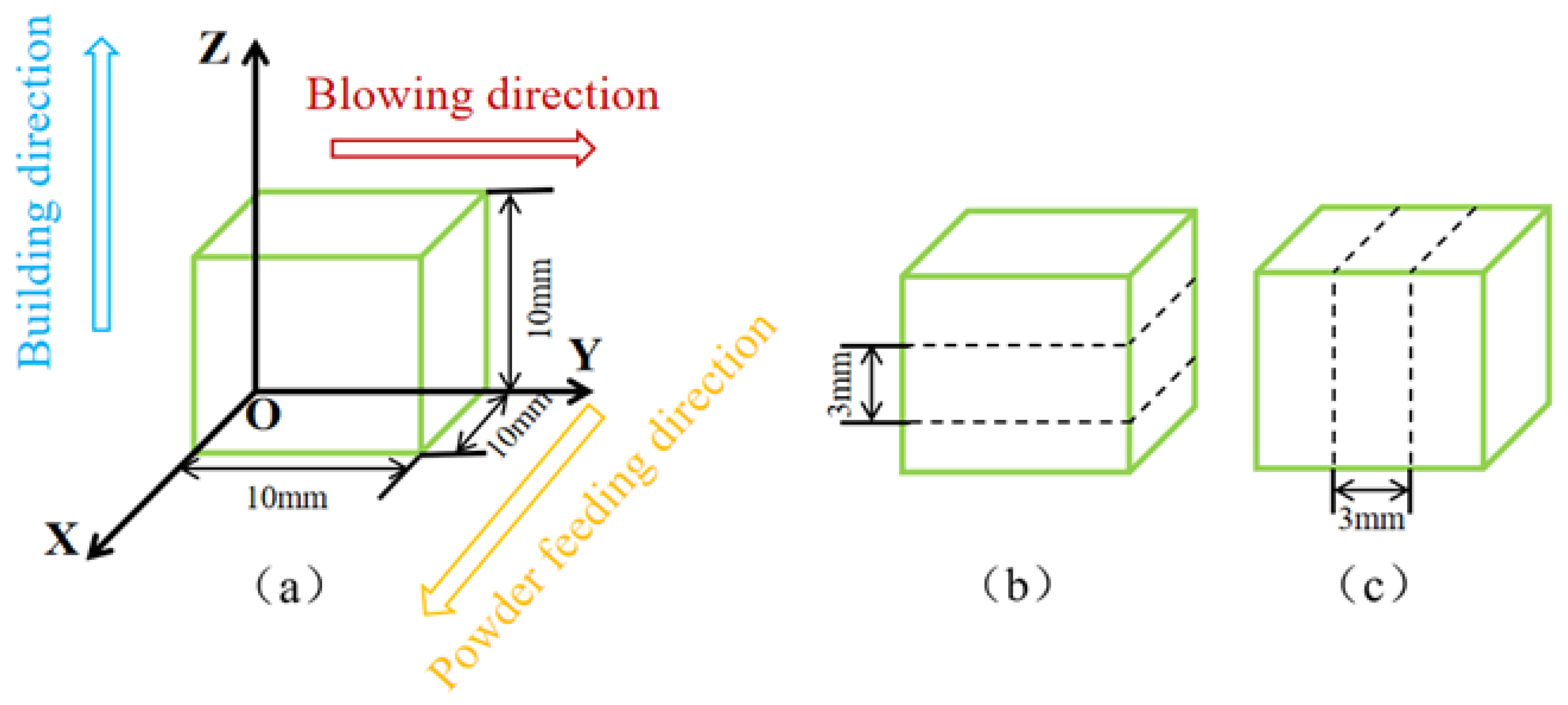
2. Materials and Methods

The studied superalloy powder used in this study was produced by vacuum gas atomisation. As shown in Figure 1a, the powder exhibited a smooth, defect-free surface morphology with a relatively uniform particle size distribution primarily ranging from 15 to 53 μm and high sphericity with few satellite particles. The chemical composition of the powder is presented in Table 1. Selective laser melting (SLM) was performed using an AFS-M260 system(Longyuan AFS Co., Ltd., Beijing, CN). Prior to fabrication, the oxygen content in the forming chamber was reduced to 500 ppm through suction and purging. Argon was used as a protective gas during the SLM process to prevent oxidation. The printing parameters were set as follows: laser power of 225 W, scanning speed of 700 mm/s, scanning spacing of 0.07 mm, and layer thickness of 0.04 mm. Multiple 10 mm × 10 mm × 10 mm samples were successfully fabricated using this SLM process.
The material deposition strategy and sample sampling locations are shown in Figure 2. The surfaces of the SLM-fabricated samples were polished using SiC sandpaper with grit sizes of 400, 800, and 1200 to achieve a smooth finish (Figure 2). The samples were then ultrasonically cleaned in ethanol for 30 min to remove any residual polishing debris and dried. The weight of each sample before the hot-corrosion experiment (m1) was recorded using a Sartorius BP211D electronic balance (Sartorius, Göttingen, Germany) with a precision of 0.01 mg.
Hot-corrosion tests were conducted in a muffle furnace using corundum crucibles. Na2SO4 was employed as the corrosive salt at a temperature of 900 °C for a duration of 100 h. The samples were initially placed on a preheated metal plate at approximately 180 °C. A saturated Na2SO4 solution was then applied evenly to the sample surfaces using an atomising spray gun (Manoli, Dongguan, CN). Upon the evaporation of the water, this resulted in the formation of a dense Na2SO4 salt film with a mass per unit area of 0.5 mg/cm2.
To study the hot-corrosion kinetics, a non-continuous weighing method was employed. The samples were removed from the furnace every 10 h, air-cooled, and weighed using the electronic balance (m2). The mass gain (Δm) was calculated as Δm = m2 − m1 to maintain a consistent salt melt environment, Na2SO4 was reapplied to the samples every 20 h. The calculation of the mass gain per unit area followed the following formula:
Δ G = Δ m A
where ΔG (mg/cm2) represents the mass gain per unit area, Δm is the mass gain, and A denotes the surface area (cm2).
The microstructure and corrosion layer morphology of the samples were characterised using an FEI Quanta 650 field-emission scanning electron microscope (FEI Company, Hillsboro, OR, USA) equipped with energy-dispersive X-ray spectroscopy (EDS). To ensure the integrity and conductivity of the corrosion layer during cross-sectional observation, the samples were coated with carbon, encapsulated in epoxy resin, and then ground and polished. Phase analysis of the corrosion products was performed using a Smartlab SE X-ray diffraction (Rigaku Corporation, Tokyo, Japan). Electron backscatter diffraction (ULVAC-PHI, Kanagawa, Japan) was employed to analyse the crystal orientation, grain size, and grain boundaries of the samples. The EBSD was analysed using TSL-OIM software (v 7.2). Further microstructural analysis of the NiCoCrW (K447A) superalloy was conducted using an FEI Technai G2 F20 transmission electron microscopy (FEI Company, Hillsboro, USA).

3. Results

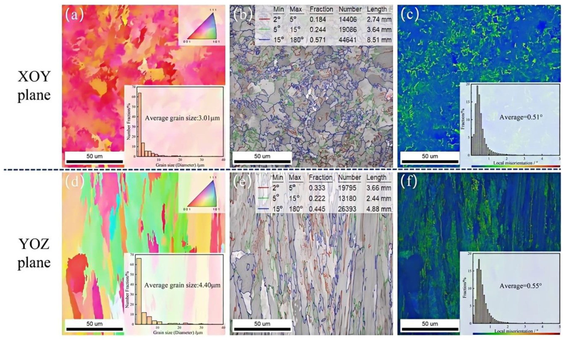
3.1. Microstructural Characterisation

Figure 3 shows the microstructure of the studied superalloy. The XOY plane (Figure 3a,b) is primarily composed of equiaxed grains and white particles, whereas the YOZ plane (Figure 3c,d) contains columnar grains and white particles. EDS analysis of the white particles revealed an enrichment of carbon, indicating they are carbides. The elemental composition of these carbides is provided in Table 2. These microstructural observations are consistent with previous studies on NiCoCrW superalloys [3,4]. The area fraction of carbides in the samples with different building directions was calculated using Image J (v 1.8.0). The results indicate that the area fractions of carbides in the XOY and YOZ planes are approximately 9.12% and 5.16%. TEM analysis was conducted to further investigate the microstructural characteristics and the carbides.
Figure 4 shows the carbide element segregation and dislocation distribution characteristics of the studied superalloy. Analysis of selected area electron diffraction patterns and EDS revealed that the carbides are MC-type carbides (M = Hf, Ti). The carbides in the XOY plane exhibit a honeycomb distribution, while those in the YOZ plane are distributed in a band-like pattern. Carbides in nickel-based superalloys can pin dislocations, enhancing the material’s strength. Their stability at high temperatures also contributes to improved hot-corrosion resistance. Therefore, the XOY plane, with its finer grain structure and more dispersed carbides, is expected to exhibit enhanced microstructural stability.
The inverse pole figure (IPF) maps in Figure 5a,d show that the grains in the XOY plane tend towards orientation, while the grains in the YOZ plane are also close to orientation. The illustrations in Figure 5a,d demonstrate that the average grain size in the XOY plane is 3.01 μm, while in the YOZ plane, it is 4.40 μm. Consistent with the SEM and TEM observations, the grain size in the XOY plane is finer. The grain boundary maps in Figure 5b,e show that the XOY plane has a larger grain boundary area due to its finer grains. The kernel average misorientation (KAM) maps in Figure 5c,f indicate a higher local stress concentration in the YOZ plane than that in the XOY plane.

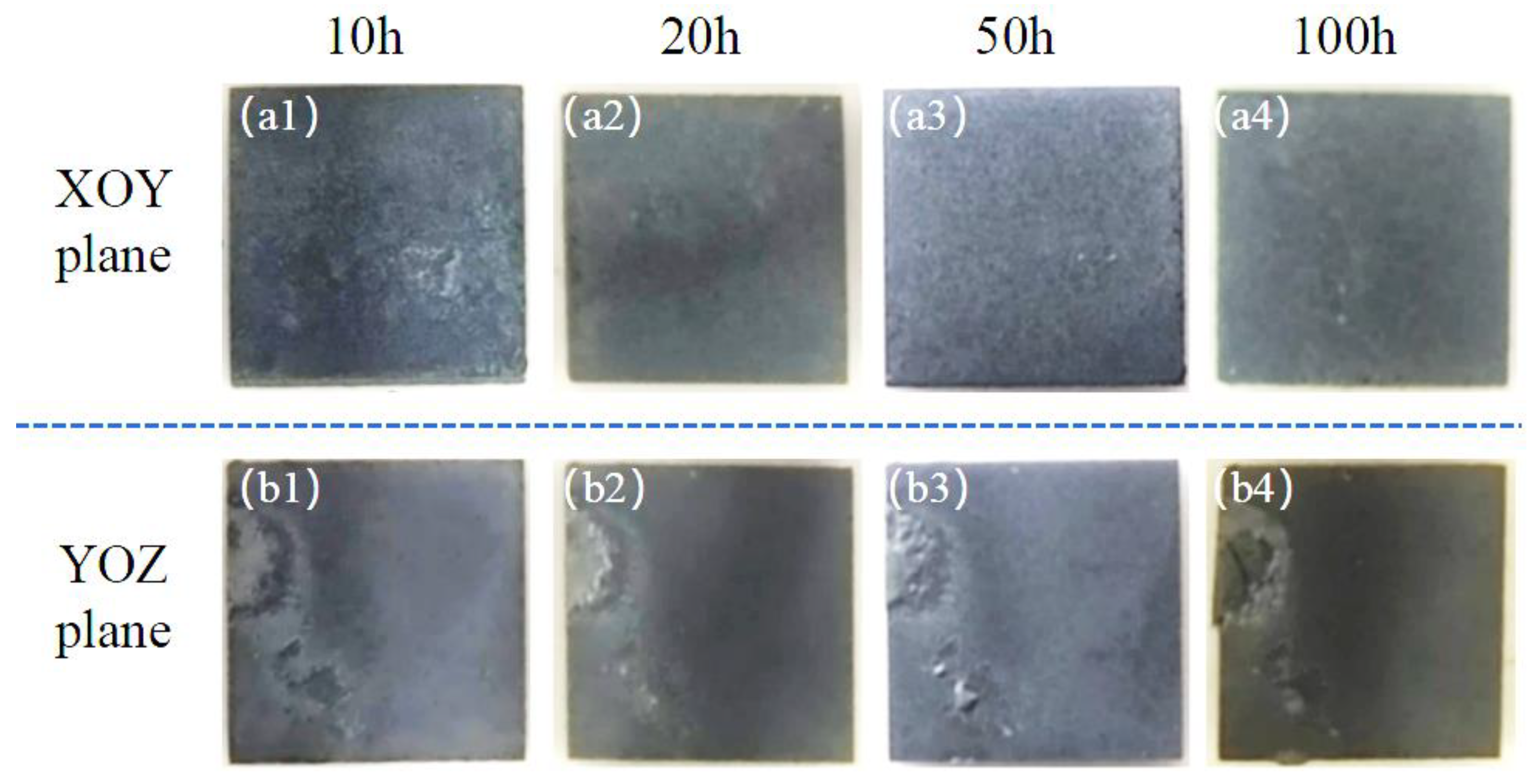
3.2. Hot-Corrosion Test Results

Figure 6 shows the surface macromorphologies of the XOY and YOZ planes after hot corrosion. The samples with different build directions exhibit different degrees of hot corrosion. After 10 h of hot corrosion, the YOZ samples showed extensive bulging on the surface, while the XOY plane remained relatively flat. After 20 and 50 h of hot corrosion, the surface roughness of the XOY plane remained relatively unchanged, whereas that of the YOZ plane specimens increased with corrosion time. After 100 h of hot corrosion, the corrosion layer on the XOY plane exhibited a better bond with the matrix, whereas the bulging parts on the YOZ plane experienced severe spalling.
The kinetic curves of the studied superalloy after corrosion for 100 h in molten Na2SO4 at 900 °C are shown in Figure 7. The mass gain due to hot corrosion at every stage on the YOZ plane is consistently higher than that on the XOY plane. After 100 h of corrosion, the unit area mass gains for the studied superalloy on the XOY and YOZ plane samples are 12.13 mg/cm2 and 18.56 mg/cm2, respectively. The average corrosion rate of the YOZ plane is 1.5 times that of the XOY plane. The hot-corrosion kinetics of the studied superalloy follows the parabolic law, and the hot-corrosion rate of the studied superalloy is represented by Equation (2) [26,27]. By comparison to other used nickel-based superalloys [18,20], both the XOY and YOZ plane samples demonstrate superior resistance to hot corrosion. The superior hot-corrosion resistance of nickel-based superalloys prepared by SLM is attributed to their better microstructural stability at high temperatures. These findings imply that the studied superalloy is well suited for applications demanding high hot-corrosion resistance.
k p = G 2 t ,
where t (h) is the time of hot corrosion, and kp (mg2·cm−4/h) is the hot-corrosion rate.

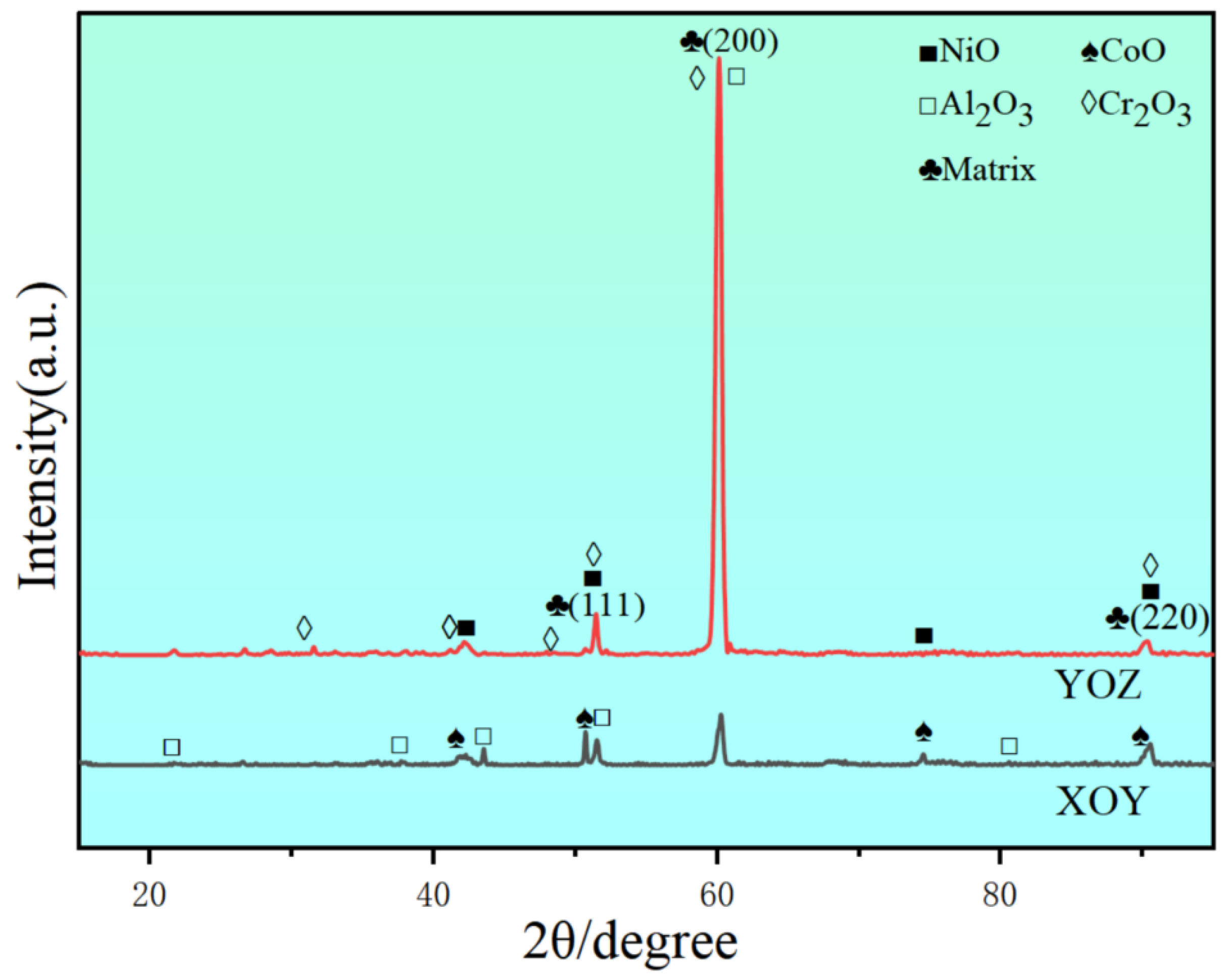
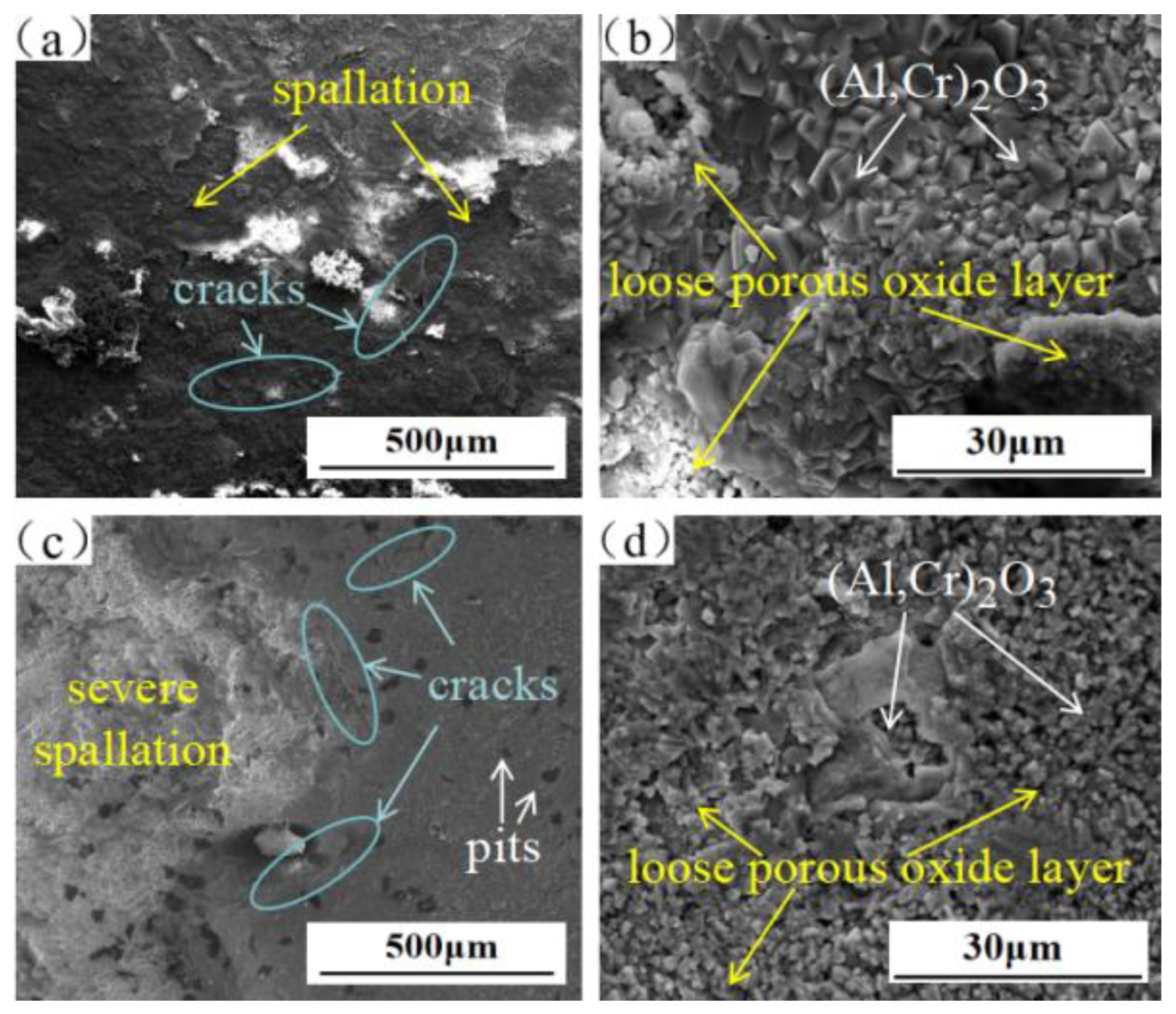
3.3. Characterisation of Hot-Corrosion Products

The XRD phase analysis of corrosion products is shown in Figure 8. After hot corrosion for 100 h in Na2SO4 at 900 °C, the corrosion products were mainly composed of oxides. At 900 °C, in addition to the Ni element, corrosion reactions also occurred for Al, Cr, Ti, and Co within the alloy. Owing to the consistent material composition, the main products of hot corrosion in samples with different building directions featured similar phase compositions. However, the microstructures of the samples with different building directions differed, and their abilities to form dense oxide films on the surface varied, leading to different relative contents of corrosion products. As shown in Figure 6 and Figure 7, the YOZ plane shows more severe corrosion, resulting in higher diffraction peak intensities of the hot-corrosion products than those in the XOY plane. And the corrosion layer on the YOZ plane experienced severe spalling, leading to the exposure of the matrix. Consequently, the intensity of the diffraction peaks for the matrix (γ/γ′) phase in the YOZ plane is higher.
Figure 9 shows the microscopic surface morphology of the XOY and YOZ plane samples after corrosion for 100 h in Na2SO4 at 900 °C. The corrosion layer on the XOY plane is relatively complete (Figure 9a), with no obvious spalling, thereby providing a certain degree of protection for the studied superalloy. The high-magnification image shown in Figure 9b shows that the oxide layer consists of dense spinel and loose clusters. Combined with XRD analysis, the dense spinel is identified as (Al,Cr)2O3, while the loose porous products are NiO, Na2CrO4, and NaNiO2. Severe spalling of the oxide layer, along with a higher prevalence of cracks and pits, is observed on the YOZ specimen surface, as shown in Figure 9c. The YOZ plane featured more cracks and pits compared to the XOY plane. Thus, the YOZ plane exhibited more severe corrosion, which is consistent with the corrosion rates depicted in Figure 7.

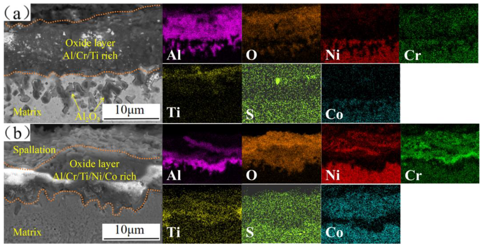
3.4. Cross-Sectional Morphologies of Corrosion Layer

Figure 10 shows the cross-sectional morphology and EDS results of the studied superalloy after hot corrosion for 100 h in Na2SO4 at 900 °C. The corrosion layer on the XOY plane is denser and more tightly bonded to the matrix, while the corrosion layer on the YOZ plane exhibits poor adhesion to the matrix. Figure 10a shows that the corrosion layer on the XOY plane is mainly composed of Al2O3 and Cr2O3. The dense Al2O3 layer can effectively prevent the corrosion of the matrix by Na2SO4. Compared to the XOY plane, the enrichment of Ni and Co within the corrosion layer on the YOZ plane is more pronounced, indicating the spalling of the Al2O3 oxide and the subsequent exposure of the matrix to Na2SO4. Additionally, the enrichment of S within the oxide layer on the XOY plane indicates that the oxide layer is more dense, preventing the diffusion of S into the matrix. Thus, S and O infiltration into the YOZ plane matrix increased the corrosion severity in the YOZ plane.

4. Discussion

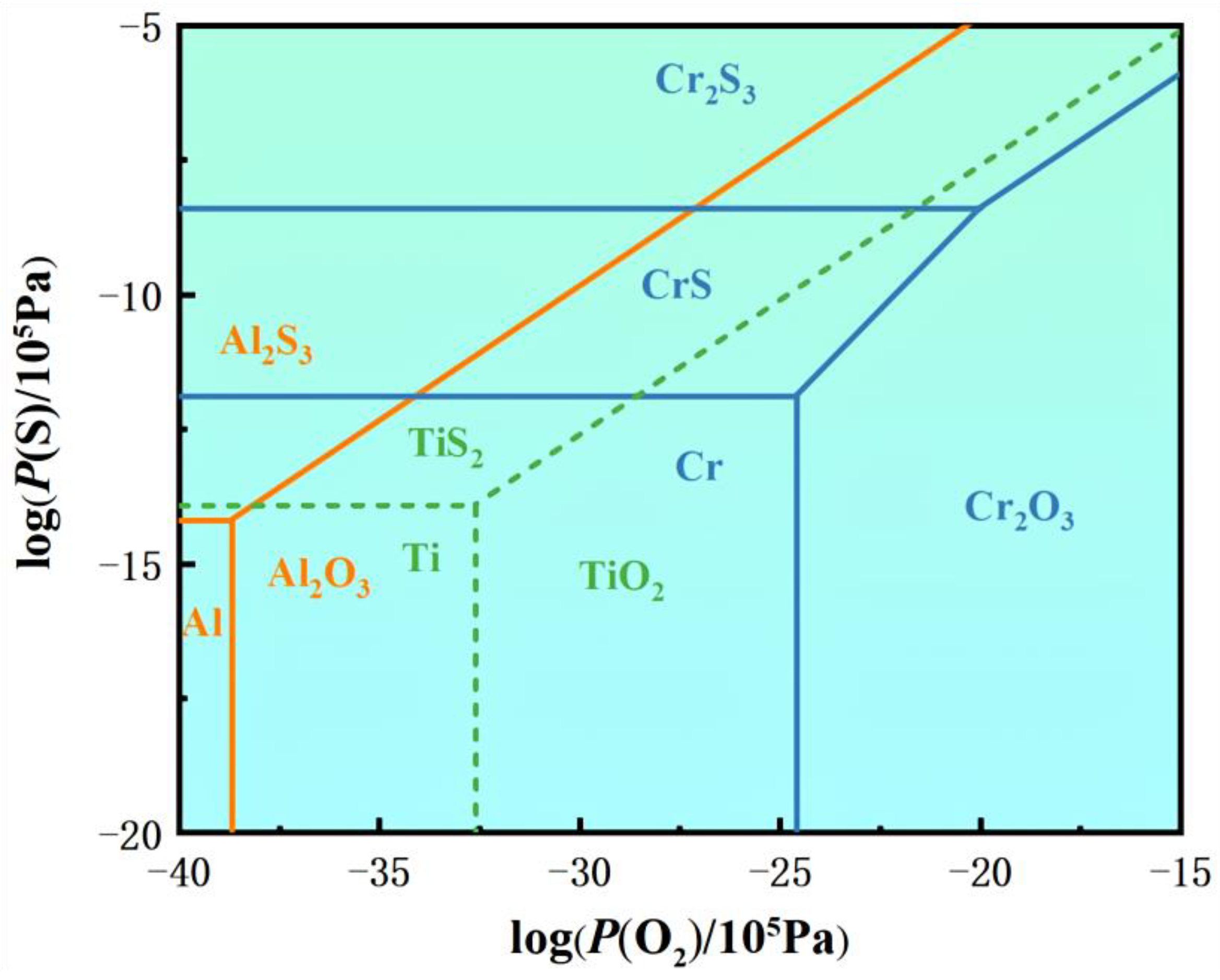
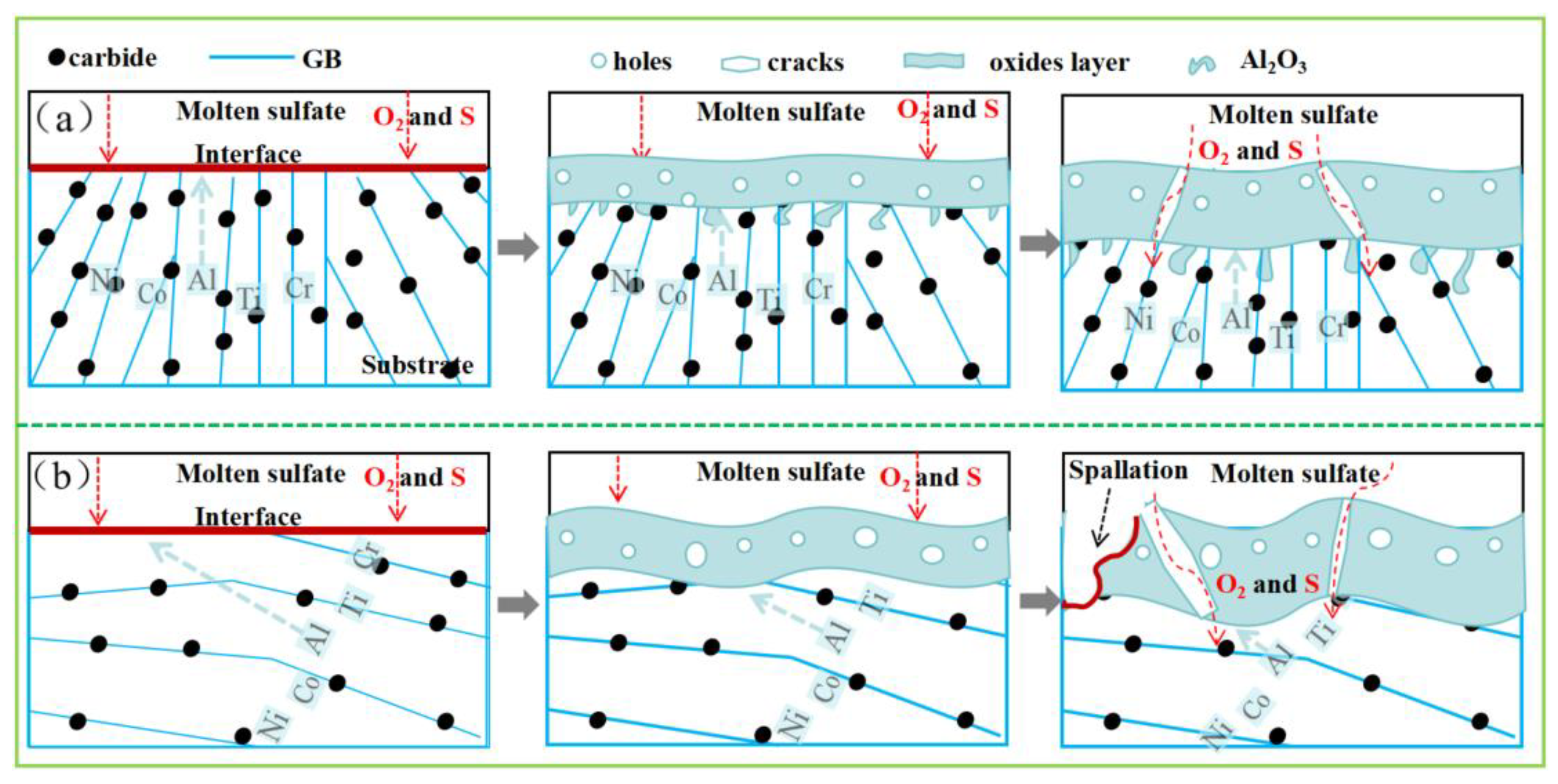
4.1. Hot-Corrosion Mechanisms

The kinetic curves in Figure 7 reveal that the hot corrosion of the studied superalloy can be divided into two stages: an initial rapid corrosion stage (0–10 h) and a subsequent stage (10–100 h) with a more stable mass gain. This behaviour is attributed to the initial interaction of Na2SO4 with the sample surface, leading to rapid hot-corrosion reactions. As corrosion progresses, a protective oxide layer forms on the surface, impeding direct contact between the corrosive medium and the superalloy. Consequently, the corrosion mechanism transitions from a surface-controlled reaction to a diffusion-controlled reaction, resulting in a reduced corrosion rate [28,29,30].
At the test temperature of 900 °C, Na2SO4 decomposes according to the following reaction [21]:
N a 2 S O 4 N a 2 O + S O 3 N a 2 O + S + O 2 ,
The essence of hot corrosion is the outward diffusion of alloy elements and the inward diffusion of O and S into the matrix. Grain boundaries facilitate the diffusion of alloy elements, promoting the formation of a dense oxide film on the sample surface, which enhances resistance to hot corrosion. However, grain boundaries also serve as diffusion pathways for S and O2, potentially leading to more severe corrosion of the matrix. The reaction between alloy elements and O2 is shown in reaction (4) [31,32,33].
Ti and Hf are primarily present as carbides at the grain boundaries. HfC is relatively stable and does not readily participate in corrosion reactions. However, when O2 diffuses through the grain boundaries, TiC reacts to form TiO2, as shown in reaction (5) [24]. The standard Gibbs free energy of oxide formation at 900 °C follows the order Al2O3 < Cr2O3 < TiO2 < CoO < NiO, as shown in Figure 11a.
x M + y 2 O 2 M x O y   M = N i , C r , C o , A l , T i ,
T i C + O 2 T i O 2 ,
The reaction between S and alloy elements is shown in reaction (6). The standard Gibbs free energy of metal sulphides at 900 °C follows the order Al2S3 < TiS2 < Cr2S3 < CrS, as shown in Figure 11b. Therefore, S reacts preferentially with Al. When Al is consumed to a certain extent, Ti reacts with S, and eventually, Cr undergoes sulphidation. As shown in Figure 12, metal sulphides can form oxides by reacting with O2 (Reaction (7)) when the O2 partial pressure is sufficiently high. S and O2 have a synergistic effect in the hot-corrosion process. As shown in reaction (3), the O2 entering the corrosion layer and the O2 released from Na2SO4 together lead to an increase in the oxygen partial pressure in the matrix, promoting the oxidation of metal sulphides.
x M + y S M x S y M = T i , C r , A l ,
M x S y + y 2 O 2 M x O y + y S M = T i , C r , A l ,
The Na2O generated from the decomposition of Na2SO4 is an important factor contributing to the severity of hot corrosion in the superalloy. The protective Cr2O3 oxide film can dissolve in the presence of Na2O to form NaNiO2 and Na2CrO4, as shown in reaction (8) [34]. In summary, the diffusion of S and O2 through grain boundaries, coupled with the dissolution of the protective oxide film by Na2O, leads to the hot corrosion of the studied superalloy.
C r 2 O 3 + N a 2 O N a 2 C r O 4 C r 2 O 3 + N a N i O 2 .

4.2. Microstructure Anisotropy Influence on Hot Corrosion

The hot-corrosion products on the XOY and YOZ sample surfaces are similar, consisting primarily of Al2O3 and Cr2O3, indicating that the fundamental hot-corrosion mechanisms are the same. During the SLM process, different building directions lead to differences in microstructure. The XOY plane sample has a finer grain size, a higher area fraction of carbides, and a more uniform carbide distribution (Figure 4 and Figure 5). Finer and more uniform grains typically reduce the stress concentration, thereby lowering the risk of corrosion cracking [18,19,23]. Grain boundaries are pinned by carbides, and the stability of grain boundaries is increased by a higher carbide area fraction, thereby reducing the stress concentration. The matrix deforms more uniformly during hot corrosion due to the uniform distribution of carbides, thereby reducing local stress, enhancing the adhesion of the oxide film, and reducing the spalling behaviour of the oxide film, thus improving the resistance to hot corrosion. Thus, the hot-corrosion performance differs significantly between the two build directions due to their distinct microstructures.
The hot-corrosion schematic of the studied superalloy in Na2SO4 at 900 °C is shown in Figure 13. S and O2 diffuse through the grain boundaries into the matrix, where they selectively react with alloying elements. TiC and HfC precipitate at the grain boundaries, and these carbides exhibit high stability. Moreover, Hf and Ti have higher oxidation resistance than Al, Ni, and Co. As shown in Figure 4, the area fraction of carbides on the XOY plane is larger, effectively slowing down the hot-corrosion rate. As hot-corrosion progresses, a dense oxide film (Al2O3 and Cr2O3) forms on the sample surface. Due to the low solubility of Na2SO4 in this oxide film, it acts as a protective barrier to the matrix, reducing the rate of hot corrosion. The finer grain size and more uniform distribution of carbides on the XOY plane result in a lower local stress concentration than that in the YOZ plane, contributing to the structural stability of the oxide film. The grain refinement increases the uniformity of the microstructure, reducing local stress and decreasing defects at the grain boundaries, which in turn reduces the diffusion paths for corrosive media. A higher carbide area fraction pins the grain boundaries, preventing slippage and promoting the formation of a dense oxide film, thereby enhancing the resistance to hot corrosion. The uniform distribution of carbides allows the matrix to deform more uniformly, reducing local stress and improving the adhesion of the oxide film, thus reducing spalling behaviour. These factors collectively act to significantly reduce the rate of hot corrosion and enhance the hot-corrosion resistance. The dissolution of Cr2O3 can lead to the formation of holes or cracks in the corrosion layer (reaction (8)). S and O2 can then diffuse through these defects to the substrate surface, where they react with the matrix, leading to further hot corrosion. Therefore, the matrix is primarily protected by the Al2O3 layer. As shown in Figure 5f, the YOZ plane exhibits greater local stress, leading to poor adhesion between the corrosion layer and the matrix. After the severe spalling of the corrosion layer, the matrix surface is re-exposed and reacts with S and O2 (reaction (4)–(7)), resulting in more severe corrosion on the YOZ plane.

5. Conclusions

In this study, a NiCoCrW (K447A) nickel-based superalloy was fabricated by selective laser melting (SLM), and its microstructure and hot-corrosion behaviour in Na2SO4 at 900 °C for 100 h were investigated. The major conclusions are summarised as follows:
  • The hot corrosion of the SLM-fabricated NiCoCrW (K447A) superalloy exhibits anisotropy in different build directions. The XOY plane (parallel to the build direction) exhibits superior hot-corrosion resistance compared to that in the YOZ plane (perpendicular to the build direction).
  • The microstructure of the NiCoCrW (K447A) superalloy shows significant anisotropy. The XOY plane has finer grains, a more uniform distribution of carbides, and a lower local stress concentration.
  • The excellent hot-corrosion resistance of the XOY plane is attributed to the larger area fraction and more uniform distribution of carbides, which contribute to the stability of the oxide film. The oxide film formed on the XOY surface is more stable, providing better protection for the underlying matrix.
Thus, this study provides a new approach for designing hot-corrosion-resistant materials fabricated by SLM. By adjusting the deposition strategy to tailor the microstructure, it is possible to enhance the material’s oxidation resistance and hot-corrosion resistance.

Author Contributions

Conceptualisation, B.H. and T.D.; methodology, B.H. and G.L.; software, B.H.; validation, G.L. and J.S.; formal analysis, B.H. and A.W.; investigation, G.L. and W.Y.; resources, W.Y.; data curation, B.H. and T.D.; writing—original draft preparation, B.H. and G.L.; writing—review and editing, T.D. and J.S.; visualisation, B.H. and J.S.; supervision, G.L. and J.S.; project administration, A.W.; funding acquisition, T.D. and A.W. All authors have read and agreed to the published version of the manuscript.

Funding

This research was funded by the Fundamental Research Funds for the Central Universities (No. 3072024XX2719) and the Independent Research and Development Funds for the Central Iron & Steel Research Institute (No. 24T60780Z).

Data Availability Statement

The original contributions presented in the study are included in the article. Further inquiries can be directed to the corresponding authors.

Conflicts of Interest

Author Geng Liu, Jie Su, Wenchao Yu and Ao Wangwas employed by China IRON and steel research institute. The remaining authors declare that the research was conducted in the absence of any commercial or financial relationships that could be construed as a potential conflict of interest.

References

  1. Dahmen, T.; Henriksen, N.G. Densification, microstructure, and mechanical properties of heat-treated MAR-M247 fabricated by Binder Jetting. Addit. Manuf. 2021, 39, 101912. [Google Scholar] [CrossRef]
  2. Yi-Lung, T.; Sea-Fue, W. Effects of alloy elements on microstructure and creep properties of fine-grained nickel-based superalloys at moderate temperatures. Mater. Sci. Eng. A 2013, 571, 155–160. [Google Scholar] [CrossRef]
  3. Zhang, Z.; Zhao, Y. The role of the pulsed-wave laser characteristics on restraining hot cracking in laser cladding non-weldable nickel-based superalloy. Mater. Des. 2021, 198, 109346. [Google Scholar] [CrossRef]
  4. Pan, C.; Yao, Z. Solidification microstructure characteristics and their formation mechanism of K447A nickel-based superalloy for dual-performance blisk. Mater. Charact. 2023, 203, 113155. [Google Scholar] [CrossRef]
  5. Baldan, R.; Rocha, P.L.R. Solutioning and Aging of MAR-M247 Nickel-Based Superalloy. J. Mater. Eng. Perform. 2013, 22, 2574–2579. [Google Scholar] [CrossRef]
  6. Navneet, K.; Kishan, Z. Review on machining of additively manufactured nickel and titanium alloys. J. Mater. Res. Technol. 2021, 15, 3192–3221. [Google Scholar] [CrossRef]
  7. Tan, J.H.K.; Sing, S.L. Microstructure modelling for metallic additive manufacturing: A review. Virtual Phys. Prototyp. 2020, 15, 87–105. [Google Scholar] [CrossRef]
  8. Sumner, J.; Encinas-Oropesa, A. Type II hot corrosion: Behavior of CMSX -4 and IN 738 LC as a function of corrosion environment. Mater. Corros. 2014, 65, 188–196. [Google Scholar] [CrossRef]
  9. Pei, Y.; Zhou, C. Improved hot corrosion resistance of Dy-Co-modified aluminide coating by pack cementation process on nickel base superalloys. Corros. Sci. 2016, 112, 710–717. [Google Scholar] [CrossRef]
  10. Qiao, M.; Zhou, C. Hot corrosion behavior of Co modified NiAl coating on nickel base superalloys. Corros. Sci. 2012, 63, 239–245. [Google Scholar] [CrossRef]
  11. Koike, R.; Unotoro, I. Evaluation for mechanical characteristics of Inconel625–SUS316L joint produced with direct energy deposition. Procedia Manuf. 2017, 14, 105–110. [Google Scholar] [CrossRef]
  12. Yuan, K.; Guo, W. Influence of process parameters and heat treatments on the microstructures and dynamic mechanical behaviors of Inconel 718 superalloy manufactured by laser metal deposition. Mater. Sci. Eng. A 2018, 721, 215–225. [Google Scholar] [CrossRef]
  13. Popovich, V.A.; Borisov, E.V. Functionally graded Inconel 718 processed by additive manufacturing: Crystallographic texture, anisotropy of microstructure and mechanical properties. Mater. Des. 2017, 114, 441–449. [Google Scholar] [CrossRef]
  14. Wilson-Heid, E.A.; Wang, Z. Quantitative relationship between anisotropic strain to failure and grain morphology in additively manufactured Ti-6Al-4V. Mater. Sci. Eng. A 2017, 706, 287–294. [Google Scholar] [CrossRef]
  15. Kouraytem, N.; Chanut, A.R. Dynamic-loading behavior and anisotropic deformation of pre- and post-heat-treated IN718 fabricated by laser powder bed fusion. Addit. Manuf. 2020, 33, 101083. [Google Scholar] [CrossRef]
  16. Sridar, S.; Pizano, L.F.L. Achieving High Strength and Creep Resistance in Inconel 740H Superalloy through Wire-Arc Additive Manufacturing and Thermodynamic-Guided Heat Treatment. Materials 2023, 16, 6388. [Google Scholar] [CrossRef]
  17. Tang, W.; Yang, X. Effect of rotation speed on microstructure and mechanical anisotropy of Al-5083 alloy builds fabricated by friction extrusion additive manufacturing. Mater. Sci. Eng. A 2022, 860, 144237. [Google Scholar] [CrossRef]
  18. Montero, X.; Ishida, A. Effect of surface treatment and crystal orientation on hot corrosion of a Ni-based single-crystal superalloy. Corros. Sci. 2020, 166, 108472. [Google Scholar] [CrossRef]
  19. Wei, B.; Chen, C. Comparing the hot corrosion of (100), (210) and (110) Ni-based superalloys exposed to the mixed salt of Na2SO4-NaCl at 750 °C: Experimental study and first-principles calculation. Corros. Sci. 2022, 195, 109996. [Google Scholar] [CrossRef]
  20. Wu, J.; Jiang, X. Anisotropy of interface characteristics between NiCoCrAlY coating and a hot corrosion resistant Ni-Based single crystal superalloy during thermal exposure at different temperatures. Appl. Surf. Sci. 2020, 532, 147405. [Google Scholar] [CrossRef]
  21. Na, G.; Meng, L. High-temperature oxidation and hot corrosion of Ni-based single crystal superalloy in the incubation stage. Corros. Sci. 2023, 214, 111026. [Google Scholar] [CrossRef]
  22. Visibile, A.; Gunduz, O.K. High temperature oxidation of inconel 939 produced by additive manufacturing. Corros. Sci. 2024, 233, 112067. [Google Scholar] [CrossRef]
  23. Liu, B.; Zhang, H. Improving the hot corrosion resistance of additively manufactured Inconel 718 via recrystallization-based grain boundary engineering induced by its residual stress. Mater. Today Commun. 2024, 39, 108792. [Google Scholar] [CrossRef]
  24. Lv, Y.; Liu, Y. Hot corrosion behavior of a novel TiC/GTD222 nickel-based composite prepared by selective laser melting. Mater. Charact. 2023, 205, 113245. [Google Scholar] [CrossRef]
  25. Yang, R.; Han, S. Hot corrosion mechanism of laser metal deposited Ni-based single crystal superalloy under fuel gas atmosphere. Surf. Coat. Technol. 2023, 474, 130057. [Google Scholar] [CrossRef]
  26. Kang, Q.; Wang, G. Experimental and theoretical study for hot corrosion behavior of network structured TiBw/TA15 composite with NaCl film at 800 °C. Corros. Sci. 2022, 206, 110540. [Google Scholar] [CrossRef]
  27. Abbaszadeh, S.; Pakseresht, A. Investigation of the High-Temperature Oxidation Behavior of the Al 0.5 CoCrFeNi High Entropy Alloy. Surf. Interfaces 2020, 21, 100724. [Google Scholar] [CrossRef]
  28. Sun, L.; Jiang, F. Microstructure and Mechanical Properties of Low-Carbon High-Strength Steel Fabricated by Wire and Arc Additive Manufacturing. Metals 2020, 10, 216. [Google Scholar] [CrossRef]
  29. Kang, Q.; Xu, X. Hot corrosion behavior of network structured TiBw/TA15 composite with Na2SO4 film at 800 °C. Mater. Charact. 2023, 195, 112499. [Google Scholar] [CrossRef]
  30. Dong, R.; Liu, D. Hot-corrosion behavior associated with the evolution of corrosion scales of a Ni-based superalloy in molten salts. Prog. Nat. Sci. Mater. Int. 2021, 31, 486–492. [Google Scholar] [CrossRef]
  31. Grégoire, B.; Montero, X. Correlations between the kinetics and the mechanisms of hot corrosion of pure nickel at 700 °C. Corros. Sci. 2019, 155, 134–145. [Google Scholar] [CrossRef]
  32. Chang, J.X.; Wang, D. Effect of Rhenium Addition on Hot Corrosion Resistance of Ni-Based Single Crystal Superalloys. Metall. Mater. Trans. 2018, 49, 4343–4352. [Google Scholar] [CrossRef]
  33. Pettit, F. Hot Corrosion of Metals and Alloys. Oxid. Met. 2011, 76, 1–21. [Google Scholar] [CrossRef]
  34. Liu, H.; Tan, C.K.I. Hot corrosion and internal spallation of laser-cladded inconel 625 superalloy coatings in molten sulfate salts. Corros. Sci. 2021, 193, 109869. [Google Scholar] [CrossRef]
Figure 1. (a) Morphology image of NiCoCrW (K447A) superalloy powder. (b) Schematic of the SLM process.
Metals 15 00338 g001
Figure 2. Deposition strategy and sampling schematic: (a) sample deposition schematic (b) along (XOY plane) and (c) perpendicular to building direction (YOZ plane).
Metals 15 00338 g002
Figure 3. SEM images of NiCoCrW (K447A) superalloy microstructural characterisation: (a,b) XOY plane; (c,d) YOZ plane.
Metals 15 00338 g003
Figure 4. TEM and EDS imaging of NiCoCrW (K447A) superalloy: (a,b) XOY plane; (c,d) YOZ plane.
Metals 15 00338 g004
Figure 5. EBSD of NiCoCrW (K447A): (a,d) IPF map (illustration is grain size data); (b,e) grain boundaries (illustration is grain boundary data); and (c,f) KAM map (illustration is misorientation data).
Metals 15 00338 g005
Figure 6. Surface macromorphologies after hot corrosion for 10, 20, 50, and 100 h.
Metals 15 00338 g006
Figure 7. Kinetic curves of the NiCoCrW (K447A) superalloy during hot corrosion in Na2SO4 at 900 °C.
Metals 15 00338 g007
Figure 8. XRD of NiCoCrW (K447A) after 100 h of corrosion at 900 °C in Na2SO4.
Metals 15 00338 g008
Figure 9. Surface morphologies of specimens after hot corrosion at 900 °C for 100 h with Na2SO4: (a,b) XOY plane; (c,d) YOZ plane.
Metals 15 00338 g009
Figure 10. SEM images of the cross-sections of corresponding EDS after hot corrosion at 900 °C for 100 h with Na2SO4: (a) XOY plane; (b) YOZ plane.
Metals 15 00338 g010
Figure 11. Standard Gibbs free energy of reacting alloy elements: (a) oxides; (b) sulphides.
Metals 15 00338 g011
Figure 12. Phase stability diagram of (Al,Cr,Ti)-O-S at 900 °C.
Metals 15 00338 g012
Figure 13. Simple schematic diagrams of hot corrosion with Na2SO4 at 100 h: (a) XOY; (b) YOZ.
Metals 15 00338 g013
Table 1. Chemical composition of NiCoCrW (K447A) superalloy powders.
ElementsCoCrMoAlTiCTaHfWNi
wt.%9.708.410.705.461.180.163.131.4610.50Bal.
Table 2. EDS results for elements (wt.%) of the composition at each point in Figure 3.
SpectrumCCrMoAlTiTaHfWNi
113.738.071.013.532.386.787.1714.4542.88
213.128.841.273.762.668.422.3014.8844.75
310.908.680.864.411.204.725.059.9954.19
412.878.010.623.751.938.213.9913.0547.57
512.257.300.613.622.7111.035.3814.2842.82
611.637.471.413.632.848.9610.0710.8843.11
Disclaimer/Publisher’s Note: The statements, opinions and data contained in all publications are solely those of the individual author(s) and contributor(s) and not of MDPI and/or the editor(s). MDPI and/or the editor(s) disclaim responsibility for any injury to people or property resulting from any ideas, methods, instructions or products referred to in the content.

