Article

Numerical Assessment on the DC Casting 7050 Aluminum Alloy Under Melt Shearing and Magnetic Fields

1
Key Laboratory of Electromagnetic Processing of Materials, Ministry of Education, Northeastern University, Shenyang 110819, China
2
School of Materials Science and Engineering, Northeastern University, Shenyang 110819, China
3
Engineering Research Center of Advanced Materials Preparing Technology, Ministry of Education, Shenyang 110819, China
*
Authors to whom correspondence should be addressed.
Metals 2025, 15(4), 360; https://doi.org/10.3390/met15040360
Submission received: 17 February 2025 / Revised: 20 March 2025 / Accepted: 21 March 2025 / Published: 25 March 2025

Abstract

:
The direct-chill (DC) casting of diameter of 300 mm 7050 aluminum alloy ingots under the impact of intense melt shearing and electromagnetic fields (combined fields) was simulated using the COMSOL software 6.2 to determine the temperature distribution and melt flow. The results indicated that the use of electromagnetic fields, intense melt shearing, and combined fields can all improve melt flow velocity, heat transfer efficiency, temperature field uniformity, and reduce sump depth when compared to conventional DC casting. However, the use of combined fields creates the shallowest sump and the most uniform temperature field. With the application of electromagnetic field, intensive melt shearing, and combined fields, the sump depth was decreased from 121 mm of DC casting to 118 mm, 112 mm, and 110 mm, respectively. Under the impact of the combined fields, the increase in the rotor rotation speed leads to the enhancement of overall flow velocity, the improvement of temperature distribution uniformity, and the reduction of melt temperature in the sump. The temperatures at reference points A and B dropped from 631.80 °C and 645.26 °C to 630.20 °C and 630.75 °C, respectively, as the rotor rotation speed increased from 1500 rpm to 6000 rpm. Additionally, the application of the combined fields resulted in a uniform microstructure distribution and notable grain refinement.

1. Introduction

The 7050 alloy is distinguished by its exceptional corrosion resistance, high specific strength, and low density [1,2,3], rendering it extensively utilized in the aerospace and transportation fields [4]. The primary technique used to produce ingots of 7050 aluminum alloy is DC casting. The solidification process of DC casting is characterized by gradual cooling from the surface to the center, forming a V-shape sump. The high alloying element content and wide solidification range of 7050 aluminum alloy result in the deep sump, leading to the formation of coarse and unevenly distributed microstructure and high hot tearing susceptibility during the DC casting process. Although the ingot’s quality and flaws can be improved by varying the casting temperature, casting speed, and cooling water flow rate, these techniques are frequently unsuccessful when producing large amounts of highly alloyed aluminum alloy ingots. Consequently, researchers are actively exploring approaches such as applying electromagnetic fields, intensive melt shearing [5], ultrasonic fields [6], and combined fields [7,8] during DC casting, to accomplish the suppression of casting flaws, grain refinement, and exact control over the temperature distribution and melt flow.
With the application of high frequency, power frequency, and low frequency magnetic field in the DC casting process, electromagnetic casting (EMC), casting refining electromagnetic (CREM) process, and low-frequency electromagnetic casting (LFEC) were developed by Getselev [9], Vives [10,11], and Cui et al. [12], respectively. EMC, CREM, and LFEC processes can all generate forced convection and result in the formation of uniform temperature distribution and significant grain refinement, while LFEC can generate stronger convection and affect the larger area in the sump, forming a more uniform temperature field and shallower sump due to the low-frequency magnetic field used in LFEC process [13,14]. Yang et al. [15] discovered that second-phase particles and grains may be efficiently refined using an electromagnetic field during DC casting. Wang et al. [16] demonstrated that applying the electromagnetic field during the casting of 7050 aluminum alloy not only improved the surface quality but also refined the grain size of the ingot. However, the convection caused by the electromagnetic field is modest in the middle of the sump and high near its edge because of the skin effect [17]. Consequently, there remain certain differences in the microstructure between the center and the edge of the ingot produced using this method [18].
The introduction of intensive melt shearing in the DC casting process also attracted the attention of researchers [5,19,20]. The intensive melt shearing technology induces strong convection by the rapid rotation of a rotor, resulting in fragmentation, dispersion, and mixing [6]. Rao [21] and Li et al. [22] demonstrated that intensive melt shearing promotes the formation of isothermal regions within the sump, accelerating the nucleation process while limiting excessive grain growth. This leads to a significant refinement of grain size and effectively mitigates the occurrence of porosity. Wei et al. [23] found that intense melt shearing-induced convection can improve heat exchange and decrease the melt’s temperature and depth in the sump. Convection caused by the intense melt shearing is mild around the sump’s border and robust in the middle [24].
It is found that applying combined fields can achieve a stronger flow field, a more uniform temperature field, and finer grain size [25,26]. Therefore, the current work proposed the combined application of electromagnetic field and intensive melt shearing in the DC casting process to fully utilize the strong convection near the sump edge induced by the electromagnetic field and the strong convection in the sump center caused by intensive melt shearing to produce a stronger and more uniform flow field and, consequently, a better control temperature field. Research on the complementary effects of intense melt shearing and electromagnetic fields in the DC casting process is still very limited, despite the combined fields’ enormous potential. When applying these combined fields during the DC casting process, it is vital to investigate the flow and temperature fields.
Due to the temperature of the melt being high and the workspace being limited during DC casting, accurately measuring the velocity and temperature of the melt through experimental methods is extremely challenging. Computational fluid mechanics (CFD) can rapidly provide intuitive results of the flow and temperature fields under single external fields [24,27] and combined impact [28] in the DC casting. In the present work, a numerical model was established and employed to simulate the flow and temperature fields during DC casting of 7050 aluminum alloy under the combined influence of intensive shearing and electromagnetic fields to further understand the grain refining effect of the combined impact.

2. Model Description

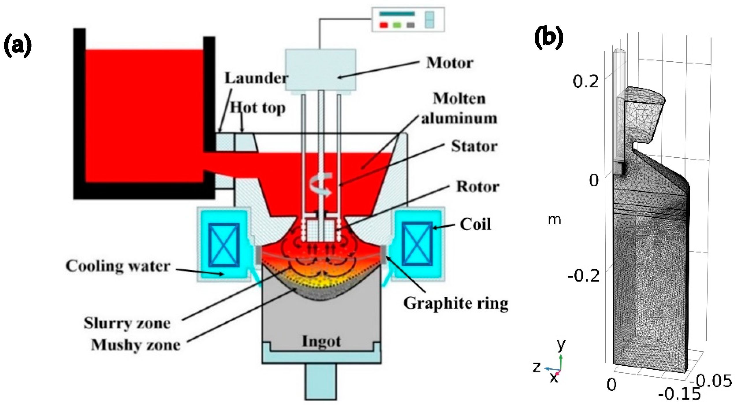
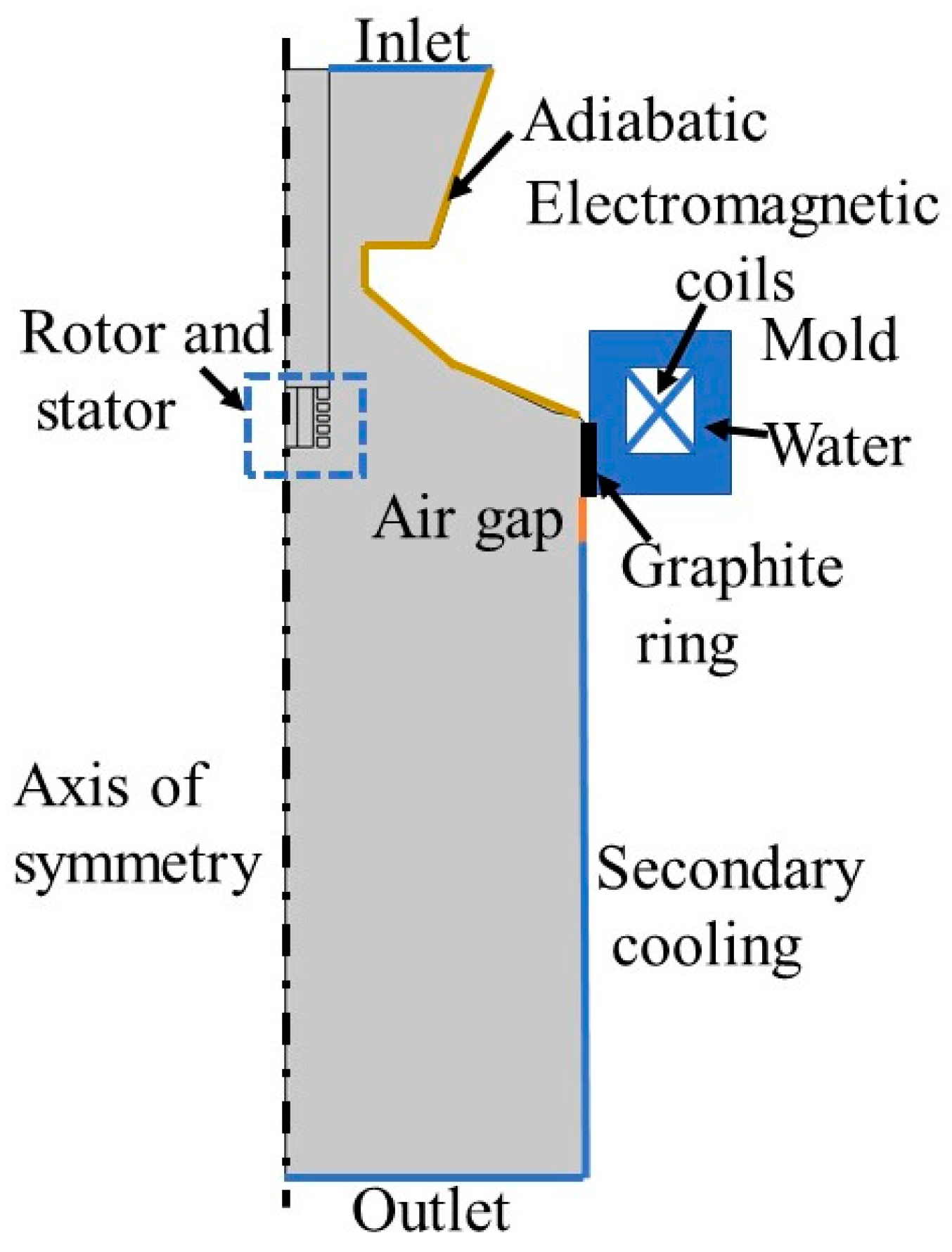
2.1. Geometric Model

With the combined fields, the schematic for the DC casting is illustrated in Figure 1a. Based on the casting process, a geometrical model with axial symmetry was constructed. For boosting computational efficiency, the cylindrical shape was scaled down to just a quarter of its full axial symmetric figure, with a height of 557 mm, as shown in Figure 1b. Within this model, the end part of the shear unit is set at a 30 mm vertical height above the upper edge of the graphite ring. The meshes were primarily discretized by extremely refined tetrahedral elements, totaling 1,290,985 elements and 227,674 vertices.

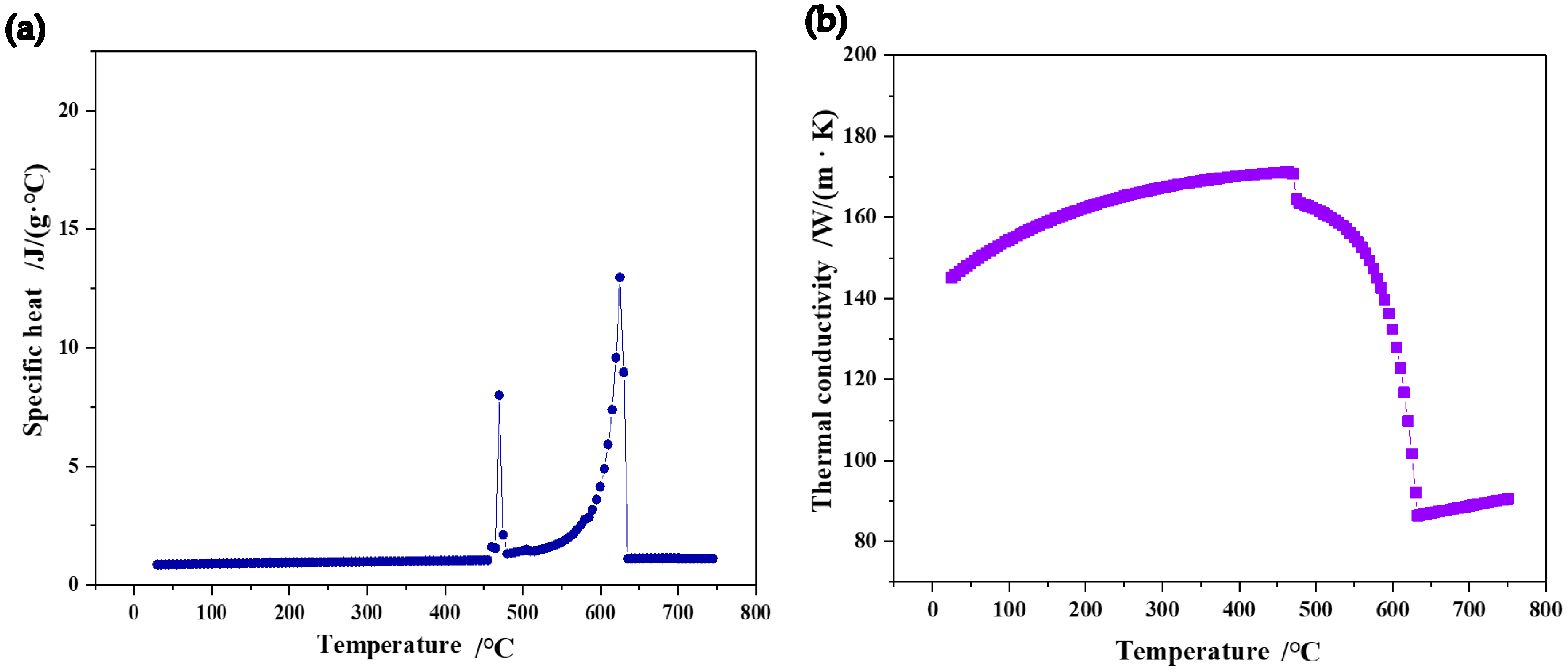
2.2. Physical Properties

Table 1 displays the composition of the 7050 aluminum alloy utilized in the article. The physical characteristics were obtained using JMatPro software 5.0. According to the data, the solidus temperature was 631 °C, the liquidus temperature was 473 °C, and the density was 2720 kg·m−3. The computed specific heat and thermal conductivity are shown in Figure 2.

2.3. Mathematical Model

2.3.1. Temperature and Flow Fields

The following is the expression for the mass conservation equation, momentum conservation equation, and energy conservation equation utilized in this investigation [29]:
  • Mass conservation equation:
· ρ U + ρ t = 0
  • Momentum conservation equation:
ρ U t + · ρ U U = · ρ l + μ + μ T U + U T + ρ β g T T r e f 1 f l 2 f l 3 + χ A m u s h U U s + ρ g + J × B
  • Energy conservation equation:
ρ T t + ρ C e f f U · T = · k T + Q
In the equations, B represents the magnetic flux density; J represents the total current density. β and λ represent the volumetric expansion coefficient and the thermal conductivity of the alloy; μ and μT denote the dynamic viscosity and turbulent viscosity; C e f f and Q denote the effective specific heat capacity and the heat source term, which includes latent heat of crystallization and Joule heating, respectively. A m u s h is the mushy zone parameter.
The high-speed rotation rotor was carried out using COMSOL 6.2 software’s rotating domain function. The standard k-ε turbulence model is employed to describe the flow conditions within the sump, as follows:
  • Turbulent kinetic energy k equation:
ρ k t + · ρ U k = · μ + μ T σ k k + P k ρ ε 1 f l 2 f l 3 + χ A m u s h k
  • ε equation for the turbulent kinetic energy dissipation rate:
ρ ε t + · ρ U ε = · μ + μ T σ ε ε + c 1 ε k P k c 2 ρ ε 2 k 1 f l 2 f l 3 + χ A m u s h ε
  • In the equation, the source term Pk is given by
P K = μ T U i X j + U j X i U i X j
  • The turbulent viscosity μT is given by
μ T = ρ c μ k 2 ε

2.3.2. Magnetic Field

To obtain the distribution and magnitude of electromagnetic force, it is essential to first calculate the values of the electric strength E and magnetic flux density B . They can be accurately obtained by solving the Maxwell equations as follows:
  • Ampère’s law:
× B = μ 0 J + μ 0 ε 0 E t
  • The law of Faraday:
× E = B t
  • The law of Gauss for magnetism:
B = 0
  • Gauss’s electric field law:
E = ρ e ε 0
In the equations, B and μ0 stand for magnetic flux density and magnetic permeability, and ε 0 for electric strength and permittivity, J for total current density, t for time, and ρ e for charge density in the equations. The following formula may be used to obtain the total current density:
J = σ E + U × B
The flow velocity and electrical conductivity are denoted by σ and U in the equations. Fluid flow has an impact on the distribution and strength of the induced current density in magnetohydrodynamics. However, the displacement current is relatively low in the electromagnetic casting process, since the magnetic Reynolds number is often considerably less than 1. Therefore, the effect of fluid flow on the induced current density can be neglected. Equation (12) can be simplified to
J = σ E
A common way to describe the electromagnetic force f is as
f = J × B

2.4. Conditions at the Boundaries

To guarantee the accuracy of the computational findings in the DC casting process, precise boundary conditions are necessary. Figure 3 is an illustration of the boundary conditions.
The primary cooling boundary condition involves heat transfer between the graphite ring and the high-temperature melt [30]:
λ T n = h T T e n
The convective heat transfer coefficient and the ambient temperature are denoted by the variables h and Ten in the equation. The following formula may be used to determine the graphite ring’s heat transfer coefficient in the mold:
h = h c o n × f l + h a i r × 1 f l
In the equation, the contact conduction coefficient hcon and the air gap conduction coefficient hair are 1500 W/(m2·K) and 25 W/(m2·K), and f l denotes the liquid fraction.
Heat transfer between the cooling water and the ingot’s surface is the secondary cooling boundary condition [31]:
h = 1.67 × 1 0 5 + 352 T + T w a t e r Q w 1 / 3 + m a x 0 , 20.8 ( T 373 ) 3 T T water
The cooling water’s temperature and flow rate are denoted by Twater and Qw in the equation. The casting speed defines the outlet boundary condition, which is adiabatic. Additionally, the boundary conditions for the hot top and symmetry axis are adiabatic.

3. Experimental Methodology and Numerical Simulation Approach

3.1. Numerical Implementation and Procedure

The Lorentz force was calculated using the magnetic field module and then incorporated into the casting process model as an interpolation function. The non-isothermal flow module was then used to compute the temperature field and flow field concurrently. The latent heat of crystallization was addressed using the equivalent specific heat approach, and a single-zone continuous model was utilized during the solidification process without taking phase transition into account. Assuming that the solid fraction in which dendritic coherence occurs is 0.4 [32], which is the dendritic coherency temperature, the liquid fraction was calculated using the Scheil model.
The following are the simulated process conditions: With a cooling water flow rate of 150 L/min, the liquid surface temperature is 675 °C. In the intense shear device, the rotor rotates at 1500 rpm, 3000 rpm, 4500 rpm, and 6000 rpm. The frequency is 20 Hz, and the current is 150 A.

3.2. Experimental Procedure

Ingots were manufactured using DC casting with and without combined fields at a casting speed of 65 mm/min in order to examine the impact of combined fields on microstructure homogeneity. The ingot’s edge, middle, and 1/2 radius were all sampled for metallography. After polishing, the samples were anodized with a 2–5% (v/v) HBF4 solution (20 V, 60 s). The OLYMPUS BX53 polarized light metallurgical microscope (Olympus Corporation, Tokyo, Japan) was used to observe the microstructure.

4. Simulation and Experimental Results

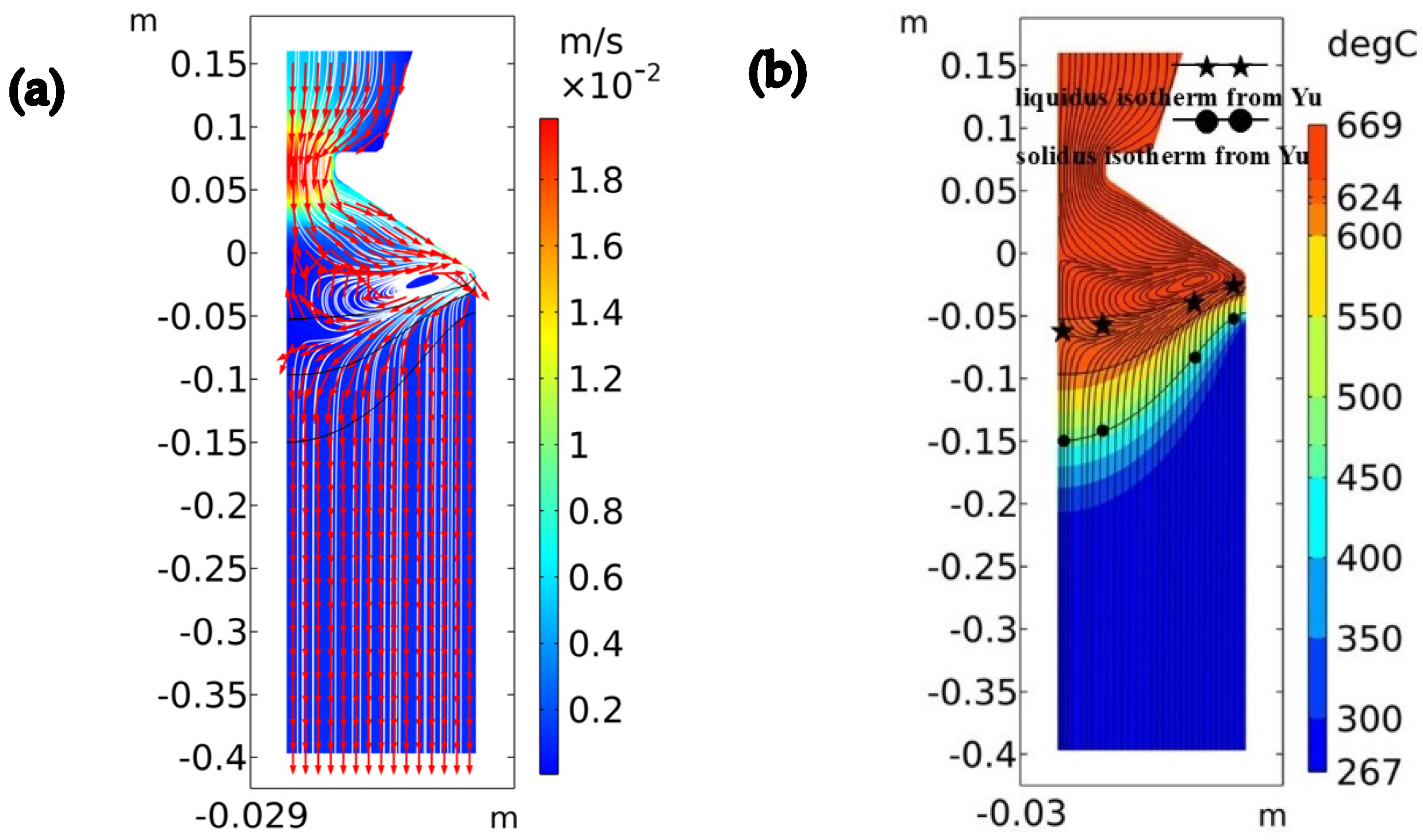
4.1. Model Validation

The accuracy and dependability of the model for simulating melt flow and temperature fields during the DC casting process of aluminum alloy with and without an external field were confirmed in the DC casting of 2024 aluminum alloy ingots [33], with and without the single application of intense melt shearing [24], and the combined applications of intense melt shearing and the magnetic field. The physical property characteristics of the 2024 aluminum alloy were swapped out for those of the 7050 aluminum alloy in the current study. By comparing the experimental data and simulation data of DC casting, it was shown that the modified model is still accurate and reliable when applied to 7050 aluminum alloy. As shown in Figure 4, there are the simulated results of the flow and temperature fields, the positions of the simulated liquidus and solidus isotherms, and the sump depth, which are similar to the results obtained by Yu et al. [34] with the same parameters.

4.2. Temperature Distribution and Melt Flow During DC Casting Using the Combined Fields

The melt first passes by the overhang, then flows downward along the mold wall, and finally recirculates back to the center of the sump along the solidification front, creating a clockwise vortex within the sump, as seen in Figure 5 on the right side to the ingot centerline during the DC casting process (casting speed of 65 mm/min). The overall melt flow pattern is not significantly altered by the application of an electromagnetic field (20 Hz, 150 A); however, the flow velocity is enhanced, especially at the narrowest point of the hot top, near the overhang, and along the solidification front. Under the influence of intensive melt shearing, the melt is drawn in from the end of the shear device and ejected through the openings of the stator towards the edge of the sump, and then it is hindered by the overhang, forming a clockwise vortex and a counterclockwise vortex. The majority of the sump is impacted by the melt of the clockwise vortex, which moves toward the ingot’s core before returning to the bottom of the intense shear device. The melt flows from the stator to the sump’s edge and back to the area around the shear device, creating a circular vortex between the overhang and the shear device. When the combined fields are applied, the melt’s flow velocity in the sump rises even more. It moves from the sump’s center to the edge, where it meets the solidification front, and then it returns to the center. The intensive melt shearing induces strong convection, and its flow direction tends to align with the vortex flow induced by the electromagnetic field, ultimately forming one dominant clockwise vortex in the center of the sump.
To further investigate the flow velocity and temperature distribution of the melt within the sump, at the same level as the upper edge of the graphite ring, point A and point B (30 mm and 135 mm from the center of the ingot, respectively) were selected as the reference points, as shown in Figure 5a. During the DC casting process, the flow velocities at point A and point B are 0.001 m/s and 0.002 m/s, respectively. With the application of electromagnetic fields, intensive melt shearing, and combined fields, the flow velocities at point A are increased to 0.002 m/s, 0.079 m/s, and 0.064 m/s, and the flow velocities at point B are increased to 0.008 m/s, 0.004 m/s, and 0.009 m/s, respectively. Compared with the application of intensive melt shearing, the application of the combined field leads to a slight decrease in melt flow velocity from 0.079 m/s to 0.064 m/s in the center of the sump, which is believed to be due to the combined fields affecting the larger volume of melt. Additionally, the position of the liquid isotherm has also undergone significant changes. The description of the slurry zone, mushy zone, and sump depth is shown in Figure 5e. Three curves from the top to the bottom are the isotherms of liquidus, dendrite coherency temperature, and solidus, respectively. In the DC casting process, the position of the liquidus isotherm is low at the center of the sump. By applying external fields, the position of the liquidus isotherm at the center of the sump is raised. During DC casting and with the application of electromagnetic fields, intensive melt shearing, and combined fields, the distances from liquidus isotherm to the liquid surface decrease from 220 mm to 170 mm, 162 mm, and 128 mm; the depths of the slurry zone in the center of the sump increase from 69 mm to 102 mm, 98 mm, and 122 mm; the depths of the mushy zone in the center of the sump change from 47 mm to 51 mm, 49 mm, and 47 mm; while the depths of the sump decrease from 121 mm to 118 mm, 112 mm, and 110 mm, respectively. This result indicates that the electromagnetic field, intensive melt shearing, and combined fields effectively accelerate the flow velocity of the melt in the sump, thereby enhancing the heat exchange efficiency between the melt and the surroundings, which leads to a reduction in the depth of the sump.
Under the influence of electromagnetic field, intensive melt shearing, and combined fields, the temperatures at point A are decreased from 650.75 °C to 631.08 °C, 640.61 °C, and 630.20 °C, and the temperatures at point B are decreased from 650.85 °C to 648.51 °C, 639.76 °C, and 630.75 °C, respectively. It can be seen that, with the combined fields, the temperature in the sump is significantly decreased, and the temperature difference between the center and the edge of the sump is only 0.55 °C, indicating that the combined fields improve the uniformity of temperature distribution.

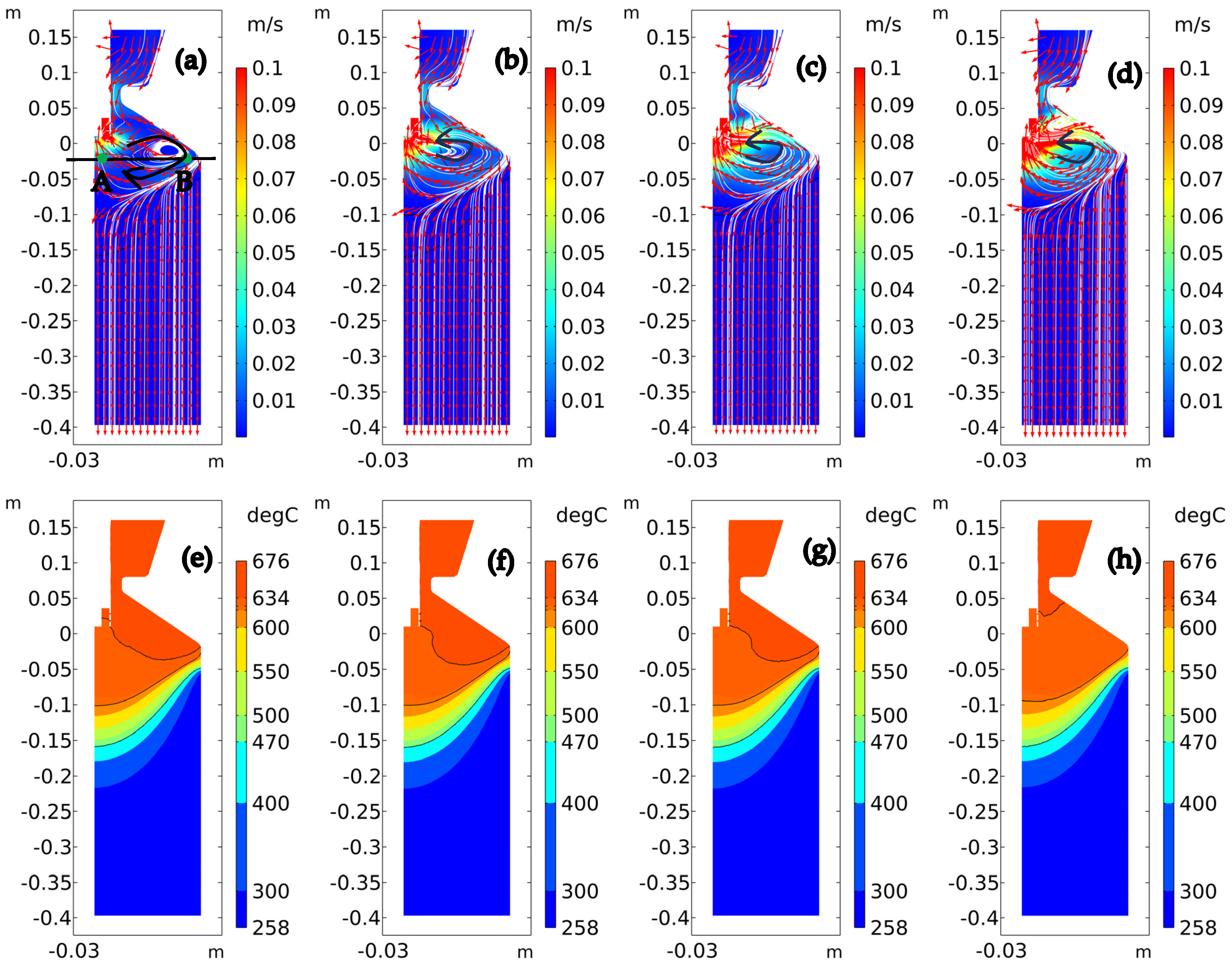
4.3. The Effect of Rotor Rotation Speed on the Melt Flow and Temperature Distribution Under Combined Fields

As was already noted, the overall flow velocity and temperature field uniformity can be greatly increased by the combined effects of intense melt shearing and electromagnetic fields. Applying many external fields has a somewhat synergistic influence on the flow patterns when compared to applying only one. Studying how the rotor rotation speed affects the flow and temperature fields during DC casting is crucial since it is a crucial parameter in combination fields. Figure 6 displays the temperature distribution and velocity vector at various rotor rotation speeds while the combined fields are at work.
A sizable vortex forms in the sump when the rotor rotation speed is set at 1500 rpm, as seen in Figure 6. The sump melt is not significantly impacted by intense melt shearing, which has a comparatively modest effect. With the center of the vortex leaning toward the sump’s edge, the electromagnetic field has a comparatively large effect on the melt’s movement. The intense shear device pulls the melt from the bottom of the device and injects it toward the sump’s edge when the rotor rotation speed reaches 3000 rpm. The melt is then impeded by the overhang and recirculates along the overhang and solidification front-back to the ingot’s center, causing a massive clockwise vortex that impacts the entire sump. Additionally, between the overhang and the intense shear device, a little anticlockwise vortex emerges. The density of the surrounding flow lines grows, the flow velocity of the melt in the sump’s center increases, and this smaller vortex progressively gets stronger when the rotor rotation speed is raised to 4500 rpm and 6000 rpm. The melt flow velocities at point A increase from 0.012 m/s to 0.031 m/s, 0.048 m/s, and 0.064 m/s as the rotor rotation speed gradually increases from 1500 rpm to 3000 rpm, 4500 rpm, and 6000 rpm; the melt flow velocities at point B remain relatively constant, changing from 0.009 m/s to 0.011 m/s, 0.012 m/s, and 0.009 m/s; the temperatures at point A change from 631.80 °C to 632.00 °C, 632.57 °C, and 630.20 °C; and the temperatures at point B decrease from 645.26 °C to 640.6 °C, 639.97 °C, and 630.75 °C, respectively. At the rotor rotation speed of 6000 rpm, the temperature of the melt at the edge of the sump is lower than the liquidus, resulting in a slight decrease in the flow velocity of the melt.

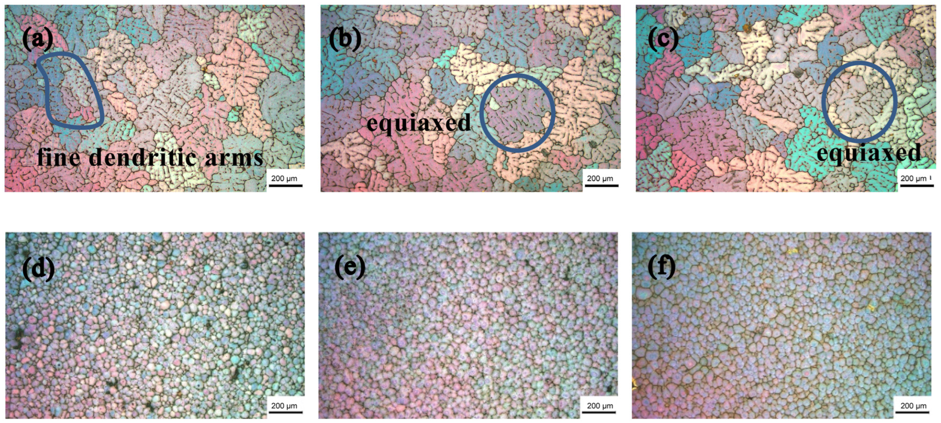
4.4. Microstructure of 7050 Aluminum Alloy Ingots Prepared with DC Casting Under Combined Fields

Figure 7 displays the findings of an observation of the microstructure of the ingots made using the traditional DC casting method and under the effect of the combined fields.
In the conventional DC casting ingot, as seen in Figure 7, the center and 1/2 radius display a coarse combination of equiaxed grains with coarse dendritic arms, whereas the edge microstructure displays fine dendritic arms. On the other hand, the ingot’s center, 1/2 radius, and edge microstructures show tiny spherical grains under the impact of the combined fields, with no discernible dendritic arms. Table 2 displays the grain sizes; the average grain size of the ingot with conventional DC casting is 274 μm, while the average grain size under the combined field is reduced to 54 μm. Therefore, the application of the combined fields results in considerable grain refinement and enhancement of the microstructure uniformity as compared to conventional DC casting.

5. Discussions

5.1. The Effect of Combined Fields on the Melt Flow and Temperature Field During DC Casting

Figure 5a illustrates how gravity and thermal buoyancy affect conventional DC casting; the flow velocity of the melt is slow, and the flow velocities at point A (center) and point B (edge) are 0.001 m/s and 0.002 m/s, respectively. The heat transfer rate of the melt is slow, resulting in high temperatures of the melt and deep sumps. The melt first moves by the overhang, then flows downward along the mold wall, and ultimately recirculates back to the center of the sump along the solidification front. This flow process creates a clockwise vortex within the sump. With the influence of the electromagnetic field, the Lorentz force accelerates the flow of the melt within the sump. As shown in Equation (14), the first term on the right hand of the equation is a rotational component which results in forced convection and increased flow velocity, significantly increasing the flow velocity at the narrowest point of the hot top, the overhang, and the solidification front at the edge of the sump. As shown in Figure 5b, the flow velocities at point A and point B are 0.002 m/s and 0.008 m/s, respectively. The Lorentz force enhances the thermal exchange efficiency between the melt and its surroundings, leading to a reduction in the depth of the sump and decreasing the melt temperature in both the center and the edge of the sump. Similarly, this promotes heat exchange at the solidification front, further decreasing the melt temperature. As shown in Figure 5c, under intensive melt shearing, the melt is drawn in from the end of the intensive shear device and ejected from the stator towards the edge of the ingot; subsequently, it is hindered by overhanging and forms two vortices, one of which is large and affects the most of the melt in the sump. The sump’s center flow velocity has considerably risen, and the flow velocities at point A and point B are 0.079 m/s and 0.004 m/s, respectively. As shown in Figure 5d, with the combined fields, intensive melt shearing induces strong convection, and its flow direction tends to align with the vortex flow induced by the electromagnetic field, ultimately forming one dominant clockwise vortex in the center of the sump. Under the influence of the combined fields, the overall flow velocity in the sump has significantly increased, the flow velocities at point A and point B are 0.064 m/s and 0.009 m/s, respectively.
During the DC casting with and without combined fields, the depths of the sump are 121 mm and 110 mm, the temperatures at point A are 650.75 °C and 630.20 °C, and the temperatures at point B are 650.85 °C and 630.75 °C, respectively. The temperature differential between the ingot’s center and edge is only 0.55 °C when combined fields are applied, suggesting that the influence of combined fields enhances heat transfer efficiency and encourages a more uniform temperature distribution.
The heat flux was computed in addition to the flow field and temperature field. The heat flux is observed at the solidification front, located 10 mm from the edge of the ingot. The heat flux at the edge of a conventional DC casting ingot is 1.1 × 10⁷ W/m2. When applying magnetic fields, intensive melt shearing, and combined fields, the heat flux increases to 6.4 × 10⁷ W/m2, 3.6 × 10⁷ W/m2, and 6.8 × 10⁷ W/m2, respectively. Therefore, the combined field significantly enhances the heat flux. Willers et al. [35] discussed the enhancement of the heat transfer coefficient caused by forced convection induced by external fields. It was believed that the formation of a uniform temperature field during DC casting is attributed to the enhanced heat transfer between the melt and the solid ingot, as well as between the melt and the mold, which is facilitated by forced convection.
At low rotor rotation rates, like 1500 rpm, the combined fields have a relatively limited effect on intensive melt shearing, which leads to the creation of a tiny vortex. Strong convection creates a tiny vortex between the intense shear device and the overhang and a big vortex in the middle of the sump when the rotor rotation speed rises to 3000 rpm and beyond. The rotor ration speed increase increases heat extraction and temperature distribution homogeneity while increasing the melt’s total flow velocity in the sump. At low rotor rotation speeds, the impact of strong convection induced by intensive melt shearing on the melt at the edge is minimal, and the electromagnetic field forces the melt to flow from the inlet to the edge of the sump, resulting in a high temperature at the edge in the sump. However, as the rotor rotation speed gradually increases, the overall flow velocity of the melt increases, resulting in improving the uniformity of temperature distribution and heat extraction rate, which leads to a decrease in temperature at the edge of the sump. When the rotor rotation speed is increased from 1500 rpm to 6000 rpm, the melt temperature at point A in the center decreases from 631.80 °C to 630.20 °C, while the temperature at point B on the edge drops from 645.26 °C to 630.75 °C. Consequently, the temperature difference between the center and the edge decreases from 13.46 °C to 0.55 °C, indicating that the increase in rotor rotation speed significantly improved the uniformity of the temperature field.
The influences of forced convection on the flow and temperature fields are characterized by the following: On one hand, forced convection facilitates the sufficient flow of the melt within the sump, promoting a more uniform distribution of temperature and solutes, thereby creating an environment conducive to the growth of equiaxed and spherical grains. On the other hand, forced convection reduces the depth of the sump, which helps minimize the differences in microstructure between the edge and the center of the ingot.

5.2. The Effect of Combined Fields on Microstructure of DC Cast 7050 Aluminum Alloy Ingot

As seen in Figure 7, the DC casting process’s combined fields may provide uniform microstructure distribution and grain refinement, which are directly tied to variations in the flow and temperature fields. The average grain size under normal DC casting is 274 μm, but when the combined fields are present, this number drops to just 54 μm, indicating that the combined fields have a refining impact on the ingot’s microstructure. The application of strong melt shear can reduce the diameter, fragmentation, and dispersion effects, and generate more dendritic fragments through mechanical fracture and melt fragmentation mechanisms [36]; this increase in nuclei is beneficial for promoting the formation of more effective nucleation sites [37]. Furthermore, forced convection improves the detachment of the nucleus from the mold wall, significantly contributing to the enhancement of the nucleation rate. Under the influence of strong convection, nuclei are distributed uniformly within the sump, which helps refine the grain size and reduces the microstructure differences between the center and the edge.

6. Conclusions

A model was established and was used to simulate the flow and temperature fields during the DC casting of a diameter of 300 mm 7050 aluminum alloy ingot under the combined influence of electromagnetic fields and intensive melt shearing. The main conclusions are as follows:
  • Compared to the conventional DC casting process, the application of electromagnetic fields, intensive melt shearing, and combined fields significantly accelerates melt flow velocity, improves uniformity of melt temperature distribution, and enhances the heat extraction in the sump, leading to the decrease in the sump depth from 121 mm to 118 mm, 112 mm, and 110 mm, respectively. The application of the combined fields resulted in the shallowest sump and a very uniform temperature field with a small temperature difference of 0.55 °C between the center (reference point A) and the edge (reference point B) in the sump.
  • The total flow velocity, temperature distribution uniformity, and melt temperature in the sump are all improved when the rotor rotation speed is increased under the impact of the combined fields. The temperature at reference point A (center) and reference point B (edge) dropped from 631.80 °C and 645.26 °C to 630.20 °C and 630.75 °C, respectively, as the rotor rotation speed increased from 1500 rpm to 6000 rpm, resulting in a significant increase in the flow velocity of the melt at the sump’s center from 0.012 m/s to 0.064 m/s.
  • Grain refinement and improved microstructure distribution uniformity may be significantly achieved by applying the combined fields throughout the DC casting process. By increasing heat transfer in the sump and speeding up flow velocity, the coupled fields lower the melt temperature and improve the nucleation process’s conditions. Increased nucleation rate, homogeneous distribution of nucleating sites within the sump, and decreased remelting of these nuclei are thought to be the mechanisms of grain refining.

Author Contributions

Conceptualization, J.W. and Y.Z.; methodology, J.W.; software, J.W.; validation, J.W., R.W. and X.G.; formal analysis, Q.Z.; investigation, J.W.; resources, Q.Z.; data curation, X.G.; writing—original draft preparation, J.W. and Y.Z.; writing—review and editing, R.W. and X.G.; visualization, Q.Z.; supervision, Y.Z.; project administration, Q.Z.; funding acquisition, Y.Z. All authors have read and agreed to the published version of the manuscript.

Funding

This work was financially supported by the National Natural Science Foundation of China (No. 51674078).

Data Availability Statement

The original contributions presented in this study are included in the article. Further inquiries can be directed to the corresponding authors.

Conflicts of Interest

The authors declare no conflict of interest.

References

  1. Lin, Y.; Jiang, Y.-Q.; Zhang, X.-C.; Deng, J.; Chen, X.-M. Effect of creep-aging processing on corrosion resistance of an Al-Zn-Mg-Cu alloy. Mater. Des. 2014, 61, 228–238. [Google Scholar] [CrossRef]
  2. Starke, E.A.; Staleyt, J.T. Application of modern aluminum alloys to aircraft. Aerospace Sci. 1996, 32, 131–172. [Google Scholar] [CrossRef]
  3. Zhang, Y.; Guo, K.; Sun, J. Investigation on the milling performance of amputating clamping supports for machining with industrial robot. Int. J. Adv. Manuf. Technol. 2019, 102, 3573–3586. [Google Scholar] [CrossRef]
  4. Azarniya, A.; Taheri, A.K.; Taheri, K.K. Recent advances in ageing of 7xxx series aluminum alloys: A physical metallurgy perspective. J. Alloy. Compd. 2019, 781, 945–983. [Google Scholar] [CrossRef]
  5. Fan, Z.Y.; Zuo, Y.B.; Jiang, B. A new technology for treating liquid metals with intensive melt shearing. Mater. Sci. Forum 2011, 690, 141–144. [Google Scholar] [CrossRef]
  6. Barbosa, J.; Puga, H. Ultrasonic melt processing in the low pressure investment casting of Al alloys. J. Mech. Work. Technol. 2017, 244, 150–156. [Google Scholar] [CrossRef]
  7. Tsunekawa, Y.; Suzuki, H.; Genma, Y. Application of ultrasonic vibration to in situ MMC process by electromagnetic melt stirring. Mater. Des. 2001, 22, 467–472. [Google Scholar] [CrossRef]
  8. Zhang, Z.; Li, J.; Yue, H.; Zhang, J.; Li, T. Microstructure evolution of A356 alloy under compound field. J. Alloy. Compd. 2009, 484, 458–462. [Google Scholar] [CrossRef]
  9. Getselev, Z.V. Casting in an electromagnetic field. J. Met. 1971, 23, 38–44. [Google Scholar] [CrossRef]
  10. Vives, C. Electromagnetic refining of aluminum alloys by the CREM process: Part II. Specific practical problems and their solutions. Met. Trans. B 1989, 20, 631–643. [Google Scholar] [CrossRef]
  11. Vives, C. Electromagnetic refining of aluminum alloys by the CREM process: Part I. Working principle and metallurgical results. Met. Trans. B 1989, 20, 623–629. [Google Scholar] [CrossRef]
  12. Cui, J.-Z.; Zhang, Z.-Q.; LE, Q.-C. DC casting of light alloys under magnetic fields. Trans. Nonferrous Met. Soc. China 2010, 20, 2046–2050. [Google Scholar] [CrossRef]
  13. Duan, W.; Bao, J.; Liu, W.; Zhang, Z.; Cui, J. Simulation on DC casting of magnesium alloy under out-of-phase pulsed magnetic field with different coil connection strategies. Int. J. Heat Mass Transf. 2020, 162, 120353. [Google Scholar] [CrossRef]
  14. Hatić, V.; Mavrič, B.; Košnik, N.; Šarler, B. Simulation of direct chill casting under the influence of a low-frequency electromagnetic field. Appl. Math. Model. 2018, 54, 170–188. [Google Scholar] [CrossRef]
  15. Yang, L.; Chen, C.; Yu, F.; Chen, C.; Liu, J.; Wang, Z.; Wang, X.; Cui, J. Coordinated deformation and high formability mechanisms of 7A36 aluminum alloy by Sc micro-alloying and low-frequency electromagnetic casting. J. Mater. Res. Technol. 2023, 24, 5186–5201. [Google Scholar] [CrossRef]
  16. Wang, X.-J.; Cui, J.-Z.; Zuo, Y.-B.; Zhao, Z.-H.; Zhang, H.-T. Effects of low-frequency electromagnetic field on the surface quality of 7050 aluminum alloy ingots during the hot-top casting process. Int. J. Miner. Met. Mater. 2011, 18, 165–168. [Google Scholar] [CrossRef]
  17. Zhou, Z.; Yang, Y.; Duan, W.; Zhang, Z.; Cui, J. Numerical simulation of DC casting of large-size rare earth magnesium alloy ingot under low-frequency electromagnetic field. Int. J. Adv. Manuf. Technol. 2022, 122, 1367–1381. [Google Scholar] [CrossRef]
  18. Bao, X.; Ma, Y.; Xing, S.; Liu, Y.; Shi, W. Effects of Pulsed Magnetic Field Melt Treatment on Grain Refinement of Al-Si-Mg-Cu-Ni Alloy Direct-Chill Casting Billet. Metals 2022, 12, 1080. [Google Scholar] [CrossRef]
  19. Lebon, G.B.; Li, H.-T.; Patel, J.B.; Assadi, H.; Fan, Z. Numerical modelling of melt-conditioned direct-chill casting. Appl. Math. Model. 2020, 77, 1310–1330. [Google Scholar] [CrossRef]
  20. Al-Helal, K.; Chang, I.; Patel, J.B.; Fan, Z. Thermomechanical Treatment of High-Shear Melt-Conditioned Twin-Roll Cast Strip of Recycled AA5754 Alloy. JOM 2018, 71, 2018–2024. [Google Scholar] [CrossRef]
  21. Rao, A.K.P. Understanding the evolution of the microstructure in melt-conditioned direct-chill cast Al alloys. Mater. Manuf. Process. 2014, 29, 848–852. [Google Scholar] [CrossRef]
  22. Li, H.-T.; Zhao, P.; Yang, R.; Patel, J.B.; Chen, X.; Fan, Z. Grain Refinement and Improvement of Solidification Defects in Direct-Chill Cast Billets of A4032 Alloy by Melt Conditioning. Met. Mater. Trans. B 2017, 48, 2481–2492. [Google Scholar] [CrossRef]
  23. Lee Wei, L.; Reddy, S.S.; AK, P.R. CFD simulation of direct chill casting process of magnesium alloy billets. J. Manuf. Process. 2019, 45, 447–454. [Google Scholar] [CrossRef]
  24. Wang, J.; Zuo, Y.; Zhu, Q.; Wang, R. Numerical simulation of the flow field and temperature field in direct-chill casting of 2024 aluminium alloy under the influence of intensive melt shearing. J. Mater. Res. Technol. 2022, 22, 1491–1504. [Google Scholar] [CrossRef]
  25. Luo, Y.; Zhang, Z. Numerical modeling of annular electromagnetic stirring with intercooling in direct chill casting of 7005 aluminum alloy billet. Prog. Nat. Sci. Mater. Int. 2019, 29, 81–87. [Google Scholar] [CrossRef]
  26. Zhao, H.; Zhang, Z.; Li, B.; Bai, Y.; Gao, M. Grain Size and Macrosegregation Control of Large-Sized AA2219 Billets by Internal Electromagnetic Stirring in DC Casting. Front. Mater. 2022, 9, 892765. [Google Scholar] [CrossRef]
  27. Duan, W.; Yang, Y.; Liu, W.; Zhang, Z.; Cui, J. Modelling the fluid flow, solidification and segregation behavior in electromagnetic DC casting of magnesium alloy. Simul. Model. Pract. Theory 2022, 115, 102460. [Google Scholar] [CrossRef]
  28. Shao, Z.; Le, Q.; Zhang, Z.; Cui, J. A new method of semi-continuous casting of AZ80 Mg alloy billets by a combination of electromagnetic and ultrasonic fields. Mater. Des. 2011, 32, 4216–4224. [Google Scholar] [CrossRef]
  29. Zou, J.; Zhang, H.; Wu, Z.; Wang, J.; Li, B.; Cui, J.; Nagaumi, H.; Li, Y. Effects of an intermittent permanent magnet stirring on the melt flow and grain refinement of Al–4.5Cu alloy. J. Mater. Res. Technol. 2021, 14, 1585–1600. [Google Scholar] [CrossRef]
  30. Khatsayuk, M.; Vinter, E.; Timofeev, V.; Belov, N.; Sergeev, N.; Pervukhin, M. Numerical Simulation of Process of Electromagnetic Casting and Technology Features. Met. Mater. Trans. B 2023, 54, 1768–1783. [Google Scholar] [CrossRef]
  31. Weckman, D.C.; Niessen, P. A numerical simulation of the D.C. continuous casting process including nucleate boiling heat transfer. J. Electron. Mater. 1992, 21, 593–602. [Google Scholar] [CrossRef]
  32. Duan, W.; Bao, J.; Liu, W.; Zhang, Z.; Cui, J. 3-D Mathematical Modeling of the Effect of Shunt Plate Hole Distribution and Magnetic Field on Transport Phenomena Within DC Casting of Magnesium Alloy Slab. Met. Mater. Trans. A 2022, 53, 2018–2039. [Google Scholar] [CrossRef]
  33. Wang, J.-C.; Zuo, Y.-B.; Zhu, Q.-F.; Li, J.; Wang, R.; Liu, X.-D. Numerical simulation of melt flow and temperature field during DC casting 2024 aluminium alloy under different casting conditions. China Foundry 2024, 21, 387–396. [Google Scholar] [CrossRef]
  34. Yu, K.; Wu, Y.; Lebon, G.S.B.; Patel, J.B.; Fan, Z.; Li, H.-T. Modeling of the Sump Profile During DC and MC-DC Casting Based on a Functional Packing Fraction. JOM 2024, 76, 6954–6961. [Google Scholar] [CrossRef]
  35. Willers, B.; Eckert, S.; Michel, U.; Haase, I.; Zouhar, G. The columnar-to-equiaxed transition in Pb–Sn alloys affected by electromagnetically driven convection. Mater. Sci. Eng. A 2005, 402, 55–65. [Google Scholar] [CrossRef]
  36. Yan, Z.; Li, X.; Cao, Z.; Zhang, X.; Li, T. Grain refinement of horizontal continuous casting of the CuNi10Fe1Mn alloy hollow billets by rotating magnetic field (RMF). Mater. Lett. 2008, 62, 4389–4392. [Google Scholar] [CrossRef]
  37. Ohno, A. Solidification: The Separation Theory and its Practical Applications; Springer: New York, NY, USA, 1987; ISBN 978-3-540-18233-7. [Google Scholar] [CrossRef]
Figure 1. (a) A diagram showing how combined fields affect the DC casting process and (b) the model’s mesh.
Metals 15 00360 g001
Figure 2. Specific heat and thermal conductivity of 7050 aluminum alloy. (a) Specific heat; (b) Thermal conductivity coefficient.
Metals 15 00360 g002
Figure 3. Descriptions of boundary conditions.
Metals 15 00360 g003
Figure 4. Flow and temperature fields of conventional DC casting: (a) flow field, (b) temperature field, and verification [34].
Metals 15 00360 g004
Figure 5. Velocity vector and temperature distribution of DC casting process: (a,e) conventional DC; (b,f) electromagnetic field; (c,g) intensive melt shearing; (d,h) combined fields; (ad) velocity vector; (eh) temperature distribution.
Metals 15 00360 g005
Figure 6. Velocity vector and temperature distribution of DC casting process at different rotor rotation speeds: (a,e) 1500 rpm; (b,f) 3000 rpm; (c,g) 4500 rpm; (d,h) 6000 rpm; (ad) velocity vector; (eh) temperature distribution.
Metals 15 00360 g006
Figure 7. Microstructure of the ingot under different conditions: (ac) conventional DC; (df) under combined fields; (a,d) the edge; (b,e) at 1/2 radius; (c,f) the center.
Metals 15 00360 g007
Table 1. Composition of 7050 aluminum alloy (wt%).
ElementsZnMgCuZrMnFeSiCrTiAl
Concentration6.02.32.20.110.050.090.080.020.05Bal
Table 2. The average grain size of DC cast 7050 aluminum alloy ingots with and without combined fields (μm).
PositionsConventional DC Castingwith Combined Fields
Edge257 ± 1047 ± 3
1/2 radius265 ± 1062 ± 3
Center302 ± 1054 ± 3
Disclaimer/Publisher’s Note: The statements, opinions and data contained in all publications are solely those of the individual author(s) and contributor(s) and not of MDPI and/or the editor(s). MDPI and/or the editor(s) disclaim responsibility for any injury to people or property resulting from any ideas, methods, instructions or products referred to in the content.

