Ultrasonic Orbital Microforming—A New Possibility in the Forming of Microparts


Institute of Manufacturing Technologies, Warsaw University of Technology, Narbutta 85, 02-524 Warsaw, Poland
Metals 2018, 8(11), 889; https://doi.org/10.3390/met8110889
Submission received: 5 October 2018
/
Revised: 22 October 2018
/
Accepted: 24 October 2018
/
Published: 31 October 2018
Abstract
:The demand for very small metal parts is growing rapidly due to the development of micromechanisms. In microtechnology, the dimensions of scale parts are below 1 + c mm, where c varies based on the process type. The “classic” processes usually cannot be simply scaled down, and tools require thorough structural changes. Microforming has been isolated from the area of “classic” metal forming and is governed by modified laws. The proposed new technological process ultrasonic orbital microforming (UOM) and its related phenomena are possible only on a microscale. UOM is a process that uses the broadly understood idea of orbital forging, which involves rolling on a closed road. This, however, is where the analogy ends. The UOM process uses completely different laws of physics. The process, the result of which is the axial-symmetrical micropart, consists of inducing a fast rotational movement of the billet by a punch that is vibrating at an ultrasonic frequency. The rotational speed is so fast that gyroscopic effect plays an important role. This work presents the concept of the process, preliminary research results, and their general interpretation. FEM-3d modeling of micro-orbital forming processes in geometrically similar conditions to the UOM process was also performed, obtaining shapes consistent with those obtained in the UOM.
1. Introduction
The twenty-first century brought an avalanche of development in microdevices applicable in almost every area of human activity (e.g., broadly understood technology, telecommunications, medicine, and defense). Microelectromechanical systems, micro-opto-electromechanical systems, microsensors, and microrobots are no longer futuristic, but reality. These devices need microparts, usually metal, and the demand for them grows rapidly. Perfectly mastered technologies for manufacturing parts on a macroscale face the challenge of reducing the size of products to the currently expected size. Such small parts must meet the requirements for dimensional accuracy and surface quality. These requirements can be met using microforming technology [1,2]. However, the direct “scaling” of this technology has encountered serious difficulties. The occurrence of the boundary size of the manufactured parts has been observed, below which the nature of physical interactions changes, and so the rules applied so far require verification. This limit size is 1 + c mm, understood as at least two dimensions of the classified object. The value of c varies depending on the type of process. As a result, a new branch of metal forming was created that deals with the production of objects that meet the above criterion: microforming technology [3,4]. Deviations from the current metal forming technological rules are called “scale or size effects” and can be applied to all the elements of the technological process. The reduction of the dimensions of the billet automatically increases the volume of the surface layer in its volume, which results in a phenomenon generally called the “surface effect”. Size reduction also results in a significant deterioration of friction conditions [5,6,7,8], an increase in galling [9], and the creation of build-ups [10]. Because of this, other models of contact phenomena, lubricants, and protective layers for microtools were developed [11,12,13]. On the other hand, reducing the size of the part reduces the number of grains in it. It can now be treated as a conglomerate of solids with various “directions” of plastic properties, which results in so-called “structural scale effects” [14,15]. One of the consequences of this is the uneven distribution of contact pressure [16]. The size of the grain affects the geometric characteristics of the product, such as the shape and quality of the surface [17], but above all affects the functional properties [18,19,20,21]. The scale effect is also applied to the construction of machines [22], instrumentation [23,24], tools [25,26,27], and technological plans [28,29,30]. Materials and friction tests using microsamples are also created because their results differ from those obtained in macrotests [31,32]. Reducing the size of manufactured parts is a serious challenge for “traditional” technologies, but at the same time it opens the possibility of using other unconventional techniques such as laser and vibration assistance, mainly by removing the energy barrier. Lasers are used in three main aspects: (1) to raise the temperature in the entire volume of the billet, transferring the treatment into warm or hot microforming areas [33]; (2) for selective heating, which may affect structural changes in selected areas or even control the shape of the objects produced [34]; and (3) as the energy that releases the wave of matter that causes the shaping, a method that can be compared to explosive forming in the macroscale [35,36,37].
Vibration support applies to two ranges: vibrations with a frequency of 50–250 Hz that cause movements of the whole tool (called “direct excitation” [38]), and ultrasonic vibrations that cause a standing wave in the tool. Both methods are attributed to an impact on microforming processes and product characteristics in many aspects. They can be divided into two basic groups: “surface effect” and “volume effect”. The first effect concerns the broadly understood contact phenomena connected with the relative movement of the tool surface in relation to the surface of the billet. It has been noticed that the introduction of vibrations favorably affects the contact phenomena, namely the lubrication breakdown [39], the tendency for galling, and the decrease of the coefficient of friction [40,41]. This applies to both low-frequency vibrations and ultrasonic vibrations [36,42]. The latter are currently intensively tested for their use in microforming. The history of attempts to apply ultrasonic vibrations dates back to the 1950s. Gale and Nevill (1957) [43] and Blaha and Langenecker (1959) [44] applied ultrasound in a low-carbon steel wire drawing test that resulted in a decrease in the strength of the process. However, they suggested a lack of direct impact of vibrations on the plastic deformation mechanism and structural changes. The decrease in strength attributed to stress superposition and temperature rose. Studies carried out in the 21st century significantly modified this view [45]. The term “acoustic softening” was widely understood [46]. It was reported that ultrasonic vibrations could cause a number of structural changes in the material of deformed objects. Researchers observed the following in vibration-assisted microforming processes: grain rotation [47], softening by dislocation annihilation [48], hardening by dislocation multiplication and point defects [49], an influence on activation energy and the generation of additional lattice vibrations [50], an influence on the dislocation motion within the grains by the formation of a new phase at the grain boundaries [51], the transformation of metallic glass into a subcooled liquid phase [52], and a smaller grain size and orientation change [53]. The use of ultrasonic vibrations may also cause macroscopic consequences, such as a change in the force of the process [54] and an increase in temperature, or can lead to creation of many cracking surfaces in the product being under deformation process [55]. The discovery of the potential for detachment of the surface of the ultrasonically excited tool from the surface of the billet during the deformation process can be considered a recent breakthrough [56]. This situation, defined as a “dynamic effect”, can take place only when a number of conditions related to the construction of the machine, tools, and process parameters are met [57]. The dynamic effect makes the microforming process similar to the forging process in a macroscale. However, one should pay attention to the enormous speed of the “ram” and the frequency of “hits”. In the entire range of the presented microforming processes, there is no analogous process to the turning process, a process that by its nature (rotational motion) leads to the formation of axially symmetrical objects. The available micromachining processes are also difficult to implement for soft materials. Further miniaturization of these materials seems to be rather complicated and difficult due to complicated equipment. The process introduced in this publication does not have the above limitations. On the other hand, it can be used only for short bars and a group of products with one or both ends widened. The ultrasonic orbital microforming (UOM) process presented within this work is a new process partially based on the use of a dynamic effect. This discovery gives a new tool and thus expands the possibilities of ultrasonic-supported microprocesses. This is the first presentation of this method, which is in the development phase.
2. Materials and Methods
The experiment setup, seen in Figure 1, consisted of a testing machine (labeled 1), a ram (2), a force transducer (3), and a die set (4). On the lower plate of the die set, a micro-die set (5) and a camera (6) were mounted. An ultrasonic system, connected with a ram, consisted of a piezoelectric transducer (7), a booster (8), and a sonotrode (9) with a punch (10) (Figure 1c). An alternating voltage oscillating at ultrasonic frequency was applied by a separate power supply unit to the piezoelectric transducer. The booster and sonotrode worked as half-wavelength resonators, vibrating lengthwise with a standing wave at its resonant frequency. The frequency used was 20 kHz.
The sonotrode acted as a displacement amplifier. The laser displacement transducer was used to measure the amplitude of vibrations on the face of the punch.
The course of the process and the shape of the product depend on the design of the tools, as shown in Figure 2a. This study envisaged the process of simple upsetting and the UOM process of cylindrical samples being produced in the microblanking process, with reduced clearance of a hardened aluminum sheet with a thickness of 1 mm. The sample is shown in Figure 2b. Reverse analysis in combination with FEM-2d modeling was used, to calculate parameters C and n of the yield curve (1), see Table 1. The remaining values: Young modulus—E, yield stress—Re and Poisson ratio—ν were adopted on the basis of the literature.
where σp is yield stress, ε is equivalent strain, and C, n are material constants.
3. Results
In the upsetting conditions, without vibrations, the processes were stable and the registration of forces proceeded smoothly. The recorded sample runs are shown in Figure 3, curves a and b.
The use of the UOM process was supplemented with the limiting plate, as seen in Figure 2a, label 4. Under these conditions, various final sample heights were carried out. The results are shown in Figure 3. Recorded process forces (with the force transducer, as seen in Figure 1a, placed “before” the ultrasonic system), should be considered unreliable due to the occurrence of the so-called dynamic effect [57,58]. Their registration and analysis were abandoned. The only example is Figure 3a, where the h curve shows the friction forces in the die set guides. The dynamic effect meant temporarily losing contact between the punch face and the sample, according to the set frequency.
4. Discussion
To analyze the results of upsetting without vibration, static modeling FEM-3d with remeshing was used with an elastic-plastic material model with strain hardening, as seen in Table 1. Friction was specified by friction coefficient μ = 0.2. The Simufact 14 package was used with the model shown in Figure 3b.
To compare the experiment with the FEM results, “loading device” deflection was taken into account. The method of analysis is described in detail in Appendix A, but results are shown in Figure 5a. On the basis of experimental curves a and b, trend lines c and d were used to construct the modified curves e and f. These curves eliminated the influence of elastic deflection on the load system and can be compared to the g curve resulting from the FEM modeling. The compared curves f and g showed good agreement.
Careful analysis of the video recording showed that during the UOM process the sample was introduced into the rotary motion as soon as the punch touched the surface of the sample. This movement then disappeared and started again after a while. This sequence was repeated several times. The spinning sample was accompanied by sound. In the pauses between the centrifugation, the sample lost contact with the punch and laid motionless on the surface of the anvil. Detailed analysis of individual recording frames is shown in Figure 6a. The film frames were chosen in such a way that they were extreme cages of two states, motion and stillness. The punch positions corresponding to them are defined as a length of the red arrows in Figure 6a. These positions in connection with the known punch velocity allowed to determine the contact times of the punch and the sample (Figure 6b).
The UOM deformation effect was analogous to the classic orbital forming processes, as seen in Appendix B. The FEM model used to model the simple upset was supplemented by inserting the kinematics of the punch, parameterized in accordance with Figure 7a. The movement of the punch is described by the position of points P0 (0,0,z0) and P1 (0,0,z1) in relation to the face of the punch, tilt angle γ, angular velocity ω, axial velocity V, and the curve C along which point P1 moves according to the equation:
The use of the orbital forming process in the FEM simulation for free upsetting resulted in the sample of the upset cylinder being immediately thrown out of the working space, as shown in Figure 7c in row A. This was counteracted by the use of a limiting plate. In this case, by selecting the appropriate process parameters (Table 3), it was possible to obtain the shapes of deformed specimens analogous to those obtained in the UOM process, as seen in Figure 7c in the rows B–D. This confirmed the rotational nature of the UOM process.
The courses of the forces of the modeled processes in relation to the force of simple upsetting are shown in Figure 7b. The orbital forming forces were definitely smaller. This was related to the contact surface of the tool, as seen in Figure 7c.
Despite the convergence of the specimen’s shapes, which was obtained by the FEM simulations and the UOM process, the actual UOM process was definitely different from orbital forming without punch vibration. It was unique in its nature. Its course was influenced by the conditions and the phenomena that accompany it, which are listed below:
- The process concerned microproducts and therefore there was a very large power reserve of the oscillatory system, which caused the system not to become damped, which then changed the system’s parameters during the deformation process;
- The so-called “dynamic effect” was present, which meant that in the conditions of the conducted process, periodic loss of contact between the punch and the sample was possible;
- Punch vibration in connection with a periodic contact with a specimen caused an acceleration in rotational motion; and
- Rapid rotational motion caused a gyroscopic moment, which stabilized the position of the sample in space.
Additionally, phenomena related to contact periodicity associated with rotational motion were expected, such as:
- Local periodic temperature increases related to friction in temporary contact areas of the tool and the sample;
- Local periodic temperature increases related to the generation of heat resulting from intense periodic plastic deformation in the contact areas;
- Periodic homogenization of the temperature distribution during periods of material deformation, as seen in the free stroke in Figure 6; and
- Thermally and mechanically generated structural changes as part of periodic deformation.
Consequently, the UOM is a unique deformation method that most likely proceeded as explained in Figure 8 and as described below.
The process started when, after a forward movement (phase SF1, as seen in Figure 6c), punch 1 touched the surface of specimen 2. The low misalignment of the punch and the specimen caused an asymmetrical impact that initially moved the sample to the edge of limiting plate 3. On the other hand, this hit caused local deformation of the sample, raised it gently, put it on the edge, and gave the punch a rotary motion in the direction of p with a small precession of angle γ. To be precise, the punch precession evoked and maintained a series of eccentric beats caused by periodic loss of contact associated with the ultrasonic vibrations of amplitude Aus. Due to its precession at the moment of contact with the sample, the punch gave it an angular acceleration. The SUOM phase began. The lifted sample rolled on anvil 4 along path Cb in the direction wb, and along path Cu toward the wu on the face of the punch. This resulted in the sample rotating around its axis toward the s. Contact of the sample with the punch and the anvil was only in the Cu and Cb zones, and was periodically lost due to ultrasonic vibrations (dotted lines wu, wb). Initially, there was a slip on the contact surface between the punch and the sample. This slippage decreased as the deformation progressed, resulting in an angular acceleration at each subsequent contact of the punch and sample.
The sample was accelerated in a rotary motion, and the gyroscopic effect caused an increase in wp1 to wp2, which meant increasing deformation. At some point, the effect of accelerating the rotary motion ended. The sample lost contact with the punch, and the punch lost precession.
The SF2 phase began. Friction forces and air resistance caused the sample rotation and gyroscopic effect to disappear, causing wp3 to decrease to zero. The sample returned to its initial position on the plane of the anvil.
A free space was created between the face of the punch and the face of the lying sample. The space was caused more by the sample under UOM conditions being deformed than by the axial displacement of the punch. If a further axial movement of the punch was planned, the SF2 phase started the next cycle. The SF2 phase continued until the punch face touched the sample surface. During the deformation of the UOM, many such cycles may occur. For example, four cycles occurred in this experiment, as seen in Figure 6b,c.
UOM, the presented mechanism of deformation, is qualitatively consistent with the experiment results, but the detailed course of phenomena and their quantitative assessment require further research and analysis.
Possible Industrial Applications
The process is in the development phase. At the current stage, it is intended for the production of short axial-symmetrical bars with variable diameters. It is a process that can be further miniaturized to a degree that is so-far difficult to determine. It also allows the processing of soft materials which are difficult to machine and grind. It achieves huge plastic deformations of the ends or end of microproducts analogous to those obtained in orbital forging on a macroscale. The parameters of the process are tool geometry, the frequency and amplitude of vibrations, progressive speed of the punch, and their mutual relations in connection with the properties and geometry of the processed billet. On the one hand, the complexity of the parameters makes their proper selection difficult, but on the other hand, it gives great possibilities for the variety of the process.
5. Conclusions
- Using microforming conditions with the use of ultrasonic vibrations, it is possible to carry out a previously unknown method of metal forming, called ultrasonic orbital microforming.
- The UOM method leads to obtaining microproducts with shapes analogous to the products obtained at the macroscale using classic orbital forming methods, which was demonstrated by FEM modeling.
- The mechanisms of deformation in the UOM method are fundamentally different from those occurring in orbital forming macroprocesses, and cannot occur in such processes. The main difference is the use of dynamic effects, such as the gyroscopic effect.
- The presented UOM mechanism is qualitatively consistent with the results obtained. However, the detailed course of phenomena and their quantitative assessment requires further research and analysis.
Funding
This research was funded by National Science Center, grant number 2011/01/B/ST8/07731.
Conflicts of Interest
The author declares no conflict of interest.
Appendix A. Compensation of the Elastic Deflection of the Load System
A precise comparison of the experimental recording of the process force with the result of the simulation required consideration of the correction resulting from the elastic deflection of the entire load system. This system is usually not included in the modeling. The force recording must therefore be corrected on the basis of an unloading curve:
The procedure is explained in Figure A1. The local component of correction due to the elastic deflection corresponding to the point i is given by Equation (A2),
where Yi is the recorded process force corresponding to point i on the unloading part of the process force, k represents the directional coefficients of the lines approximating the relief, and δxi represents the local components of correction due to elastic deflection.
The elastic correction of the position of the point corresponding to the process force is equal to the sum of all components of the elastic corrections up to the considered force point, and is given by the formula
where Δxi represents the corrections of the displacement positions due to elastic deflection.
Figure A1.
Modification of process force F to Fmod, meaning the reduction of elastic deflection of the load system.
Figure A1.
Modification of process force F to Fmod, meaning the reduction of elastic deflection of the load system.
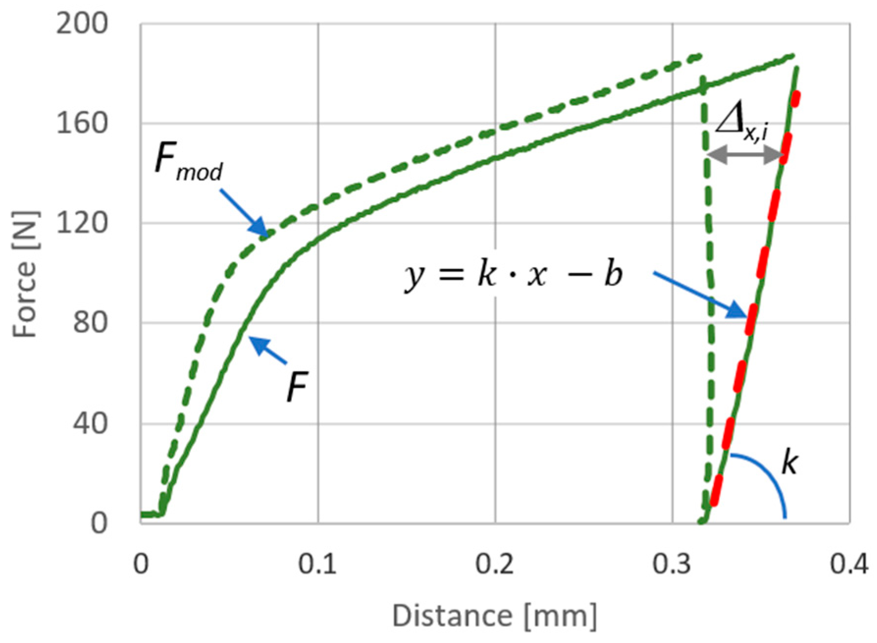
The recorded process force, which is a set of measuring points after the modification consisting of taking the elastic correction into account, is transformed into a set according to the equation
where F is a set of measured points and Fmod is a set of points taking into account the correction due to elastic deformations of the load system (i.e., the machine, tools, and tooling).
Appendix B. Orbital Forming
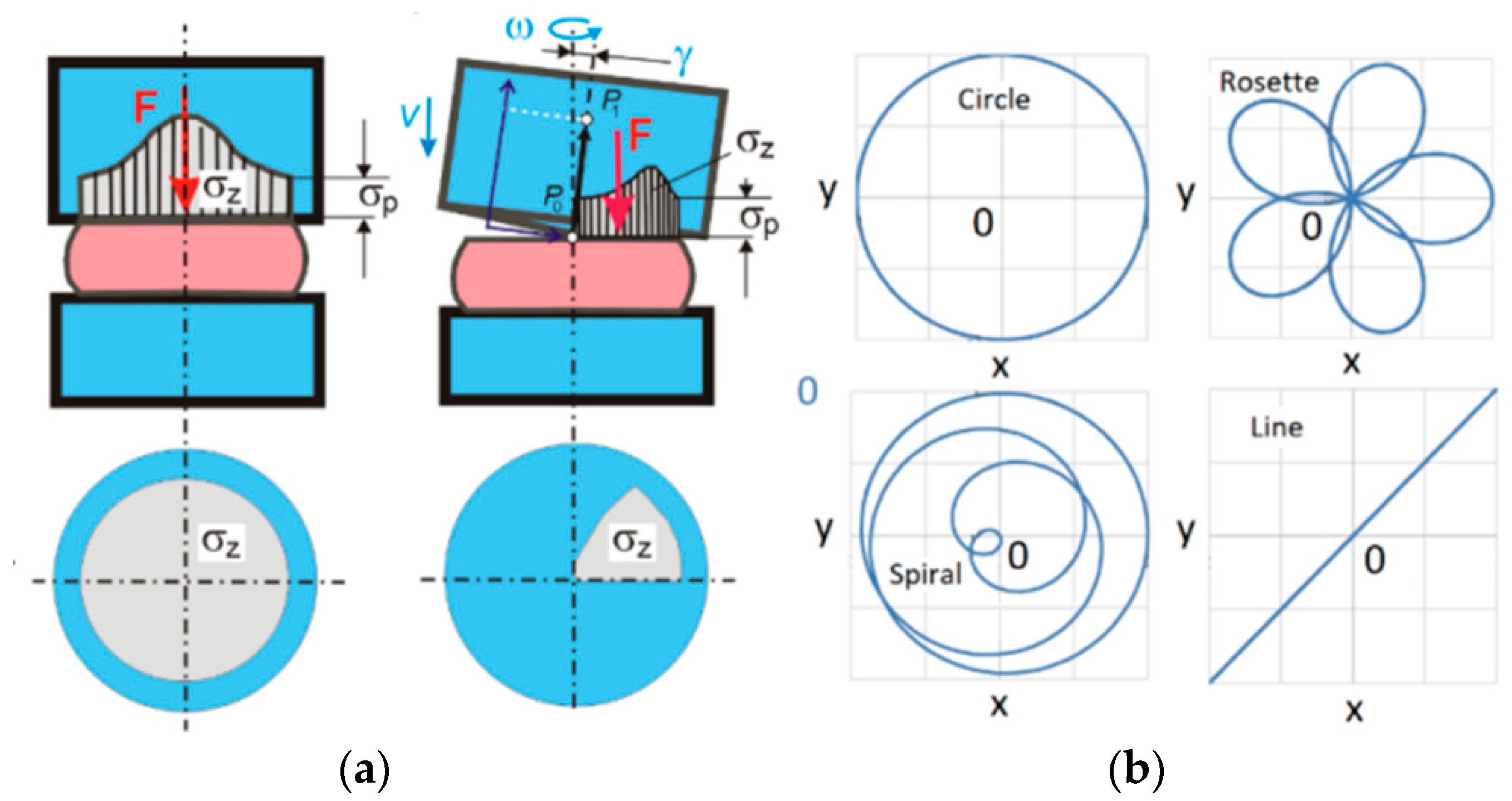
Orbital forming [59,60] is analogous to rolling along a closed path. The punch moves around the circumference, affecting only a part of the surface of the deformed product. It is an incremental process, which involves reducing the maximum process force in relation to the classical upsetting force [61]. A comparison of the classical and orbital processes is shown in Figure 1a.
The kinematics of presses that implement this type of process usually consist of the submission of two circular movements with independent drives [44]. Such a machine has the theoretical possibility of implementing the entire path area described by Equation (A5) and shown in Figure A2b:
where r is the radius of the curve and P, Q, are parameters resulting in the type of path of movement, as seen in Figure A2b [62].
Figure A2.
(a) Comparison of classical and orbital forging, where F is the process force, σz is the axial stress, σp is the yield stress, and γ is the tilt angle; and (b) Movements obtainable in accordance with Equation (A5).
Figure A2.
(a) Comparison of classical and orbital forging, where F is the process force, σz is the axial stress, σp is the yield stress, and γ is the tilt angle; and (b) Movements obtainable in accordance with Equation (A5).
References
- Santome, Y.; Hiroyuki, I. Superplastic backward microextrusion of microparts for micro-electro-mechanical systems. J. Mater. Process. Technol. 2001, 119, 307–311. [Google Scholar] [CrossRef]
- Geiger, M.; Engel, U.; Vollertsen, F.; Kals, R.; Meßner, A. Metal forming of micro parts for electronics. Prod. Eng. 1994, 2, 15–18. [Google Scholar] [CrossRef]
- Engel, U.; Rosochowski, A.; Geißdörfer, S.; Olejnik, L. Microforming and Nanomaterials. In Advances in Material Forming: Esaform 10 Years on; Springer Science & Business Media: Berlin, Germany, 2007; ISBN 9782287721427. [Google Scholar]
- Geiger, M.; Kleiner, M.; Eckstein, R.; Tiesler, N.; Engel, U. Microforming. CIRP Ann. 2001, 50, 445–462. [Google Scholar] [CrossRef]
- Taureza, M.; Song, X.; Castagne, S. On the influence of workpiece material on friction in micro forming and lubricant effectiveness. J. Mater. Process. Technol. 2014, 214, 998–1007. [Google Scholar] [CrossRef]
- Engel, U. Tribology in microforming. Wear 2006, 260, 265–273. [Google Scholar] [CrossRef]
- Jeon, J.; Bramley, A.N. A friction model for microforming. Int. J. Adv. Manuf. Technol. 2007, 33, 125–129. [Google Scholar] [CrossRef]
- Wang, C.; Guo, B.; Shan, D. Friction related size-effect in microforming—A review. Manuf. Rev. 2014, 1, 23. [Google Scholar] [CrossRef]
- Muster, A.; Presz, W. Influence of initial surface roughness on galling behaviour of steel-steel couple. Scand. J. Metall. 1999, 28, 5–8. [Google Scholar]
- Presz, W.; Kaczorowski, M. Strengthening Mechanisms of 1H18N9T Austenitic Steel Buildups Created with Cold Forming Processes. Adv. Mater. Res. 2007, 23, 165–168. [Google Scholar] [CrossRef]
- Shimizu, T.; Komiya, H.; Watanabe, T.; Teranishi, Y.; Nagasaka, H.; Morikawa, K.; Yang, M. HIPIMS deposition of TiAlN films on inner wall of micro-dies and its applicability in micro-sheet metal forming. Surf. Coat. Technol. 2014, 250, 44–51. [Google Scholar] [CrossRef]
- Presz, W. Contact Phenomena in Micro-Blanking. Int. J. Mater. Form. 2008, 1, 471–474. [Google Scholar] [CrossRef]
- Wang, C.; Guo, B.; Shan, D.; Zhang, M.; Bai, X. Tribological behaviors in microforming considering microscopically trapped lubricant at contact interface. Int. J. Adv. Manuf. Technol. 2014, 71, 2083–2090. [Google Scholar] [CrossRef]
- Golanski, D.; Dymny, G.; Kujawińska, M.; Tomasz, C. Experimental investigation of displacement/strain fields in metal coatings deposited on ceramic substrates by thermal spraying. Solid State Phenom. 2016, 240, 174–182. [Google Scholar] [CrossRef]
- Shimizu, T.; Kakegawa, T.; Yang, M. Micro-texturing of DLC thin film coatings and its tribological performance under dry sliding friction for microforming operation. Proc. Eng. 2014, 81, 1884–1889. [Google Scholar] [CrossRef]
- Diehl, A.; Engel, U.; Geiger, M. Influence of microstructure on the mechanical properties and the forming behaviour of very thin metal foils. Int. J. Adv. Manuf. Technol. 2010, 47, 53–61. [Google Scholar] [CrossRef]
- Chan, W.L.; Fu, M.W.; Yang, B. Experimental studies of the size effect affected microscale plastic deformation in micro upsetting process. Mater. Sci. Eng. A 2012, 534, 374–383. [Google Scholar] [CrossRef]
- Kocanda, A.; Presz, W.; Adamczyk, G.; Czyżewski, P.; Mazurek, M. Contact pressure distribution in upsetting of compound metals. J. Mater. Process. Technol. 1996, 60, 343–348. [Google Scholar] [CrossRef]
- Presz, W.; Rosochowski, A. The Influence of Grain Size on Surface Quality of Microformed Components. In Proceedings of the 9th International ESAFORM Conference on Material Forming, Glasgow, UK, 26–28 April 2006. [Google Scholar]
- Ghassemali, E.; Tan, M.J.; Wah, C.B.; Jarfors, A.E.W.; Lim, S.C.V. Grain size and workpiece dimension effects on material flow in an open-die micro-forging/extrusion process. Mater. Sci. Eng. A 2013, 582, 379–388. [Google Scholar] [CrossRef]
- Chang, T.A.; Razali, A.R.; Zainudin, N.A.I.; Yap, W.L. Size Effects in Thin Sheet Metal Forming. In Proceedings of the 3rd International Conference of Mechanical Engineering Research, Kuantan, Malaysia, 18–19 August 2015. [Google Scholar]
- Ran, J.Q.; Fu, M.W.; Chan, W.L. The influence of size effect on the ductile fracture in micro-scaled plastic deformation. Int. J. Plast. 2013, 41, 65–81. [Google Scholar] [CrossRef]
- Raulea, L.V.; Goijaerts, A.M.; Govaert, L.E.; Baaijens, F.P.T. Size effect in the processing of thin metal sheets. J. Mater. Process. Technol. 2001, 115, 44–48. [Google Scholar] [CrossRef]
- Presz, W.; Andersen, B.; Wanheim, T. Piezoelectric driven Micro-press for microforming. J. Achiev. Mater. Manuf. Eng. 2006, 18, 411–414. [Google Scholar]
- Cannella, E.; Nielsen, E.K.; Stolfi, A. Designing a Tool System for Lowering Friction during the Ejection of In-Die Sintered Micro Gears. Micromachines 2017, 8, 214. [Google Scholar] [CrossRef]
- Paldan, N.A.; Arentoft, M.; Eriksen, R.S.; Mangeot, S. Piezo driven prestressing of die-system for microforming of metal components. Int. J. Mater. Form. 2008, 1, 467–470. [Google Scholar] [CrossRef]
- Presz, W. Scale effect in design of the pre-stressed micro-dies for microforming. Comput. Meth. Mater. Sci. 2016, 16, 196–203. [Google Scholar]
- Presz, W.; Rosochowski, M. Application of semi-physical modeling of interface surface roughness in design of pre-stressed microforming dies. Proc. Eng. 2017, 207, 1004–1009. [Google Scholar] [CrossRef]
- Wang, C.J.; Shan, D.B.; Zhou, J.; Guo, B.; Sun, L.N. Size effects of the cavity dimension on the microforming ability during coining process. J. Mater. Proc. Technol. 2007, 187, 256–259. [Google Scholar] [CrossRef]
- Ghassemali, E.; Jarfors, A.E.W.; Tan, M.J.; Lim, S.C.V. On the microstructure of micro-pins manufactured by a novel progressive microforming process. Int. J. Mater. Form. 2013, 6, 65–74. [Google Scholar] [CrossRef]
- Stellin, T.; van Tijum, R.; Engel, U. Modelling and experimental study of a microforging process from metal strip for the reduction of defects in mass production. Prod. Eng. 2016, 10, 103–112. [Google Scholar] [CrossRef]
- Gong, F.; Guo, B. Size effects on mechanical properties of copper thin sheet in uniaxial tensile tests. Medziagotyra. 2014, 20, 509–512. [Google Scholar] [CrossRef]
- Presz, W. The Method of Micro-Upsetting in Uneven Temperature Distribution. In Proceedings of the 27th International Conference on Metallurgy and Materials, Brno, Czech Republic, 23–25 May 2018. [Google Scholar]
- Wulfsberg, J.P.; Terzi, M. Investigation of laser heating in microforming applying sapphire tools. CIRP Ann. Manuf. Technol. 2007, 56, 321–326. [Google Scholar] [CrossRef]
- Li, Y.; Quick, N.R.; Kar, A. Dieless laser drawing of fine metal wires. J. Mater. Process. Technol. 2002, 123, 451–458. [Google Scholar] [CrossRef]
- Gao, H.; Cheng, G.J. Laser-induced high-strain-rate superplastic 3-D microforming of metallic thin films. J. Microelectromech. Syst. 2010, 19, 273–281. [Google Scholar] [CrossRef]
- Liu, H.-X.; Li, J.-W.; Zhang, Q.; Shen, Z.-B.; Qian, Q.; Zhang, H.-F.; Wang, X. Warm microforming using a laser-driven flyer. Lasers Eng. 2017, 36, 89–102. [Google Scholar]
- Je, G.; Malka, D.; Kim, H.; Hong, S.; Shin, B. A study on micro hydroforming using shock wave of 355 nm UV-pulsed laser. Appl. Surf. Sci. 2017, 417, 244–249. [Google Scholar] [CrossRef]
- Presz, W. The Influence of Punch Vibration on Surface Phenomena in Micro-Extrusion. In Proceedings of the 9th International ESAFORM Conference on Material Forming, Glasgow, UK, 26–28 April 2006. [Google Scholar]
- Ngaile, G.; Bunget, C. Influence of ultrasonic vibration on microforming. Trans. NAMRI/SME 2008, 36, 137–144. [Google Scholar]
- Dawson, G.R.; Winsper, C.E.; Snasome, D.H. Application of high- and low-frequency oscillation to the plastic deformation of metals. Met. Form. 1970, 37, 254–261. [Google Scholar]
- Presz, W. The Method of Determining the Tendency to Galling in Vibration Assisted Microforming. In Proceedings of the 27th International Conference on Metallurgy and Materials, Brno, Czech Republic, 23–25 May 2018. [Google Scholar]
- Djavanroodi, F.; Ahmadian, H.; Koohkan, K.; Naseri, R. Ultrasonic assisted-ECAP. Ultrasonics 2013, 53, 1089–1096. [Google Scholar] [CrossRef] [PubMed]
- Gale, E.; Nevill, J.F. The Effect of Vibrations on the Static Yield Strength of a Low–Carbon Steel. ASTM Proc. 1957, 57, 751–758. [Google Scholar]
- Blaha, F.; Langenecker, B. Plastizitätsuntersuchungen von metallkristallen in ultraschallfeld. Acta Metall. 1959, 7, 93–100. [Google Scholar] [CrossRef]
- Daud, Y.; Lucas, M.; Huang, Z. Modelling the effects of superimposed ultrasonic vibrations on tension and compression tests of aluminium. J. Mater. Process. Technol. 2007, 186, 179–190. [Google Scholar] [CrossRef]
- Siddiq, A.; El Sayed, T. Acoustic softening in metals during ultrasonic assisted deformation via CP-FEM. Mater. Lett. 2011, 65, 356–359. [Google Scholar] [CrossRef]
- Siu, K.W.; Ngan, A.H.W. Understanding acoustoplasticity through dislocation dynamics. Philos. Mag. 2011, 91, 4367–4387. [Google Scholar] [CrossRef] [Green Version]
- Lum, I.; Huang, H.; Chang, B.H.; Mayer, M.; Du, D.; Zhou, Y. Effects of superimposed ultrasound on deformation of gold. J. Appl. Phys. 2009, 105, 902–905. [Google Scholar] [CrossRef]
- Abhishek, P.; Verma, G.C.; Hariharan, K.; Pandey, P.M.; Lee, M.G.; Suwas, S. Dislocation density based constitutive model for ultrasonic assisted deformation. Mech. Res. Commun. 2017, 85, 76–80. [Google Scholar]
- Mordyuk, B.M.; Karasevs’Ka, O.P.; Rudoi, P.E.; Skyba, I.O.; Kamins’Kyi, H.H. Influence of ultrasonic vibrations on the phase transformation and strain hardening of a Zr18Nb alloy in tension. Mater. Sci. 2013, 48, 546–554. [Google Scholar] [CrossRef]
- Presz, W.; Kulik, T. Ultrasonic vibrations as an impulse for glass transition in micro-forming of bulk metallic glass. Arch. Civ. Mech. Eng. 2018, 19, 100–113. [Google Scholar] [CrossRef]
- Myshlyaev, M.M.; Shpeizman, V.V.; Klubovich, V.V.; Kulak, M.M.; Lyu, G. Change in Characteristics of Superplastic Deformation of the Aluminum–Lithium Alloy under the Effect of Ultrasonic Vibrations. Phys. Solid State 2015, 57, 2039–2044. [Google Scholar] [CrossRef]
- Zhou, H.; Cui, H.; Qin, Q.H.; Wang, H.; Shen, Y. A comparative study of mechanical and microstructural characteristics of aluminium and titanium undergoing ultrasonic assisted compression testing. Mater. Sci. Eng. A 2017, 682, 376–388. [Google Scholar] [CrossRef]
- Luo, F.; Li, K.; Zhong, J.; Gong, F.; Wu, X.; Ruan, S. An ultrasonic microforming process for thin sheet metals and its replication abilities. J. Mater. Process. Technol. 2015, 216, 10–18. [Google Scholar] [CrossRef]
- Bunget, C.; Ngaile, G. Influence of ultrasonic vibration on micro-extrusion. Ultrasonics 2011, 51, 606–616. [Google Scholar] [CrossRef] [PubMed] [Green Version]
- Presz, W.; Cacko, R. Ultrasonic assisted microforming. In Proceedings of the METAL 2017–26th International Conference on Metallurgy and Materials, Brno, Czech Republic, 24–26 May 2017. [Google Scholar]
- Hu, J.; Shimizu, T.; Yang, M.I. Investigation on ultrasonic volume effects: Stress superposition, acoustic softening and dynamic impact. Ultrason. Sonochem. 2018, 48, 240–248. [Google Scholar] [CrossRef] [PubMed]
- Presz, W. Dynamic effect in ultrasonic assisted micro-upsetting. In Proceedings of the AIP Conference Proceedings, Palermo, Italy, 23–25 April 2018. [Google Scholar]
- Schondelmaier, J. Grundlagenuntersuchung uber das Taumelpressen; Springer: Berlin/Heidelberg, Germany, 1992. [Google Scholar]
- Han, X.; Hua, L. Comparison between cold rotary forging and conventional forging. J. Mech. Sci. Technol. 2009, 23, 2668–2678. [Google Scholar] [CrossRef]
- Plancak, M.E.; Vilotic, D.Z.; Stefanovic, M.C. Orbital Forging—A plausible alternative for bulk metal forging. Trends Dev. Mach. Assoc. Technol. 2012, 16, 63–66. [Google Scholar]
Figure 1.
The experiment stand: (a) Overview; (b) Close-up of the working area; and (c) The ultrasonic system. Legend: (1) the testing machine; (2) the ram; (3) the force transducer; (4) the die set; (5) the micro-die set; (6) the camera; (7) the ultrasonic transducer; (8) the booster; (9) the sonotrode; and (10) the punch.
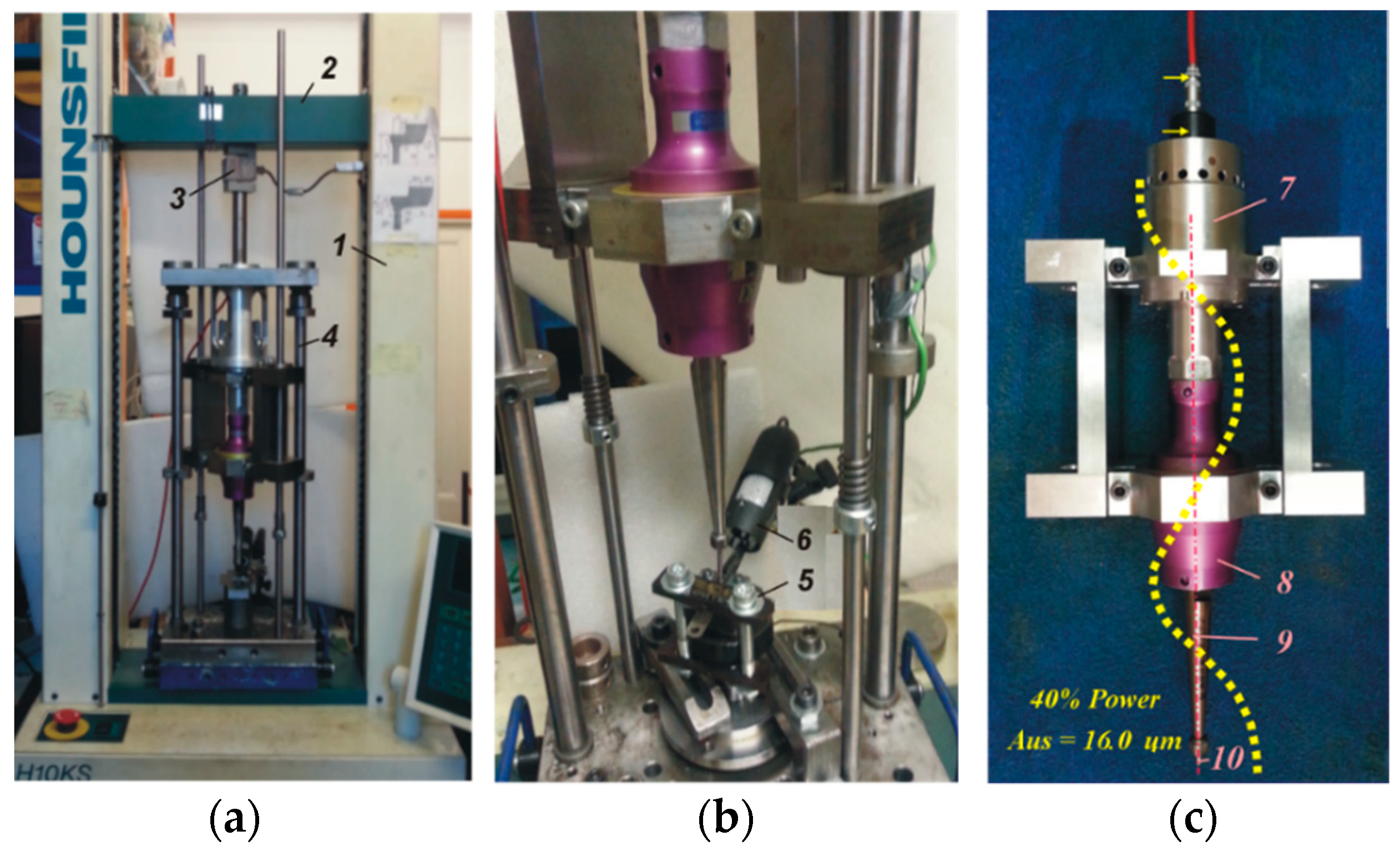
Figure 2.
(a) The main details and dimensions of micro-upsetting; and (b) SEM of the specimen. Legend: (1) the specimen; (2) the anvil; (3) the punch; and (4) the limiting plate, which was optional.
Figure 2.
(a) The main details and dimensions of micro-upsetting; and (b) SEM of the specimen. Legend: (1) the specimen; (2) the anvil; (3) the punch; and (4) the limiting plate, which was optional.

Figure 3.
(a) Process forces, where a and b are simple upsetting and h is UOM; and (b) a deformed specimen (force course b) and outlines of deformed specimens (force courses a and b).
Figure 3.
(a) Process forces, where a and b are simple upsetting and h is UOM; and (b) a deformed specimen (force course b) and outlines of deformed specimens (force courses a and b).
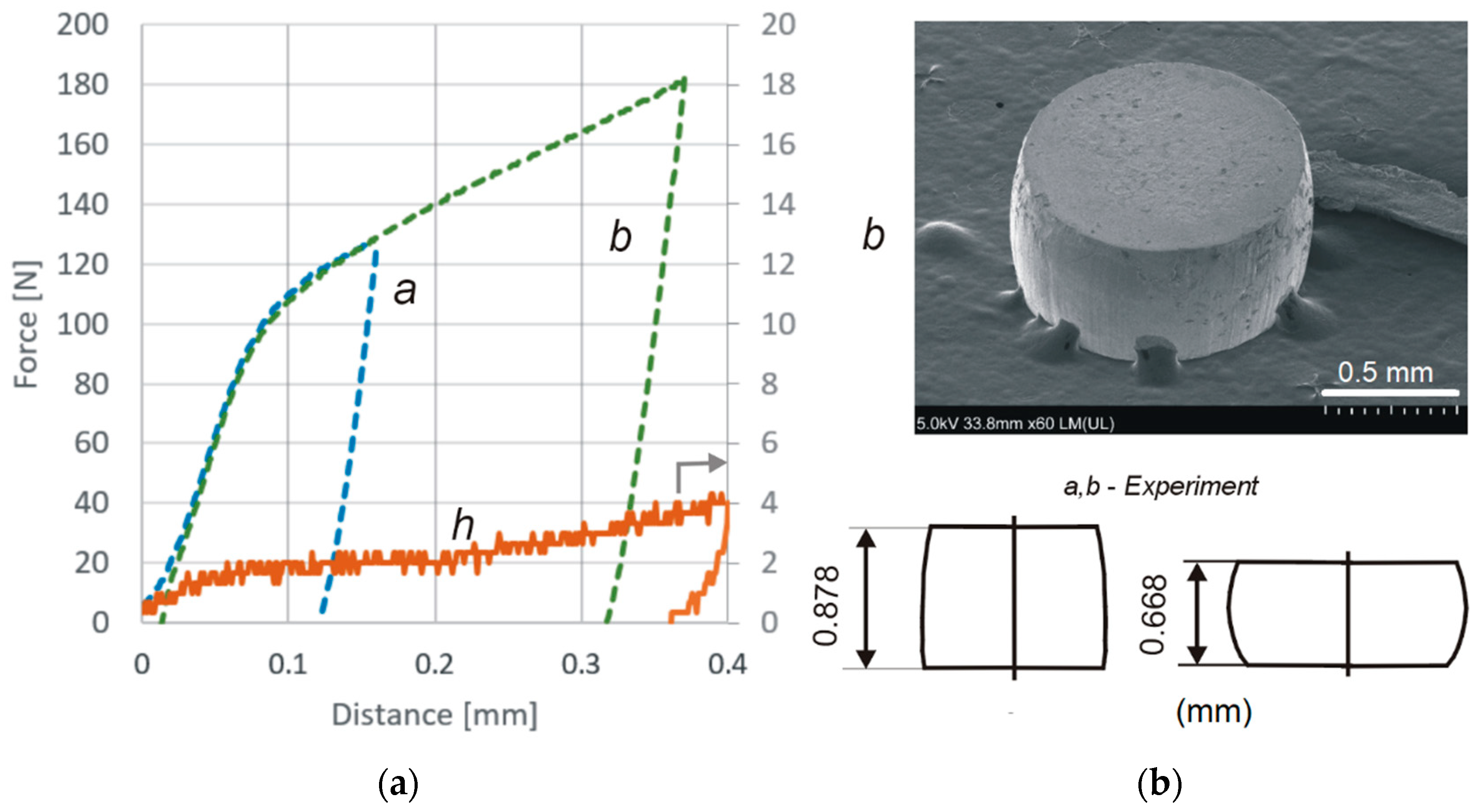
Figure 4.
Specimens after ultrasonic upsetting: (a) pictures; (b) SEM; (c); outlines; and (d) sample frames from the recorded movie of the process.
Figure 4.
Specimens after ultrasonic upsetting: (a) pictures; (b) SEM; (c); outlines; and (d) sample frames from the recorded movie of the process.

Figure 5.
Results of the simple upsetting experiment and FEM-3d modeling: (a) process forces and their analysis-description in text; (b) FEM-3d model of simple upsetting and equivalent strain distribution; and (c) FEM-3d model of orbital upsetting, including the punch (1), specimen (2), anvil (3), and plate (4).
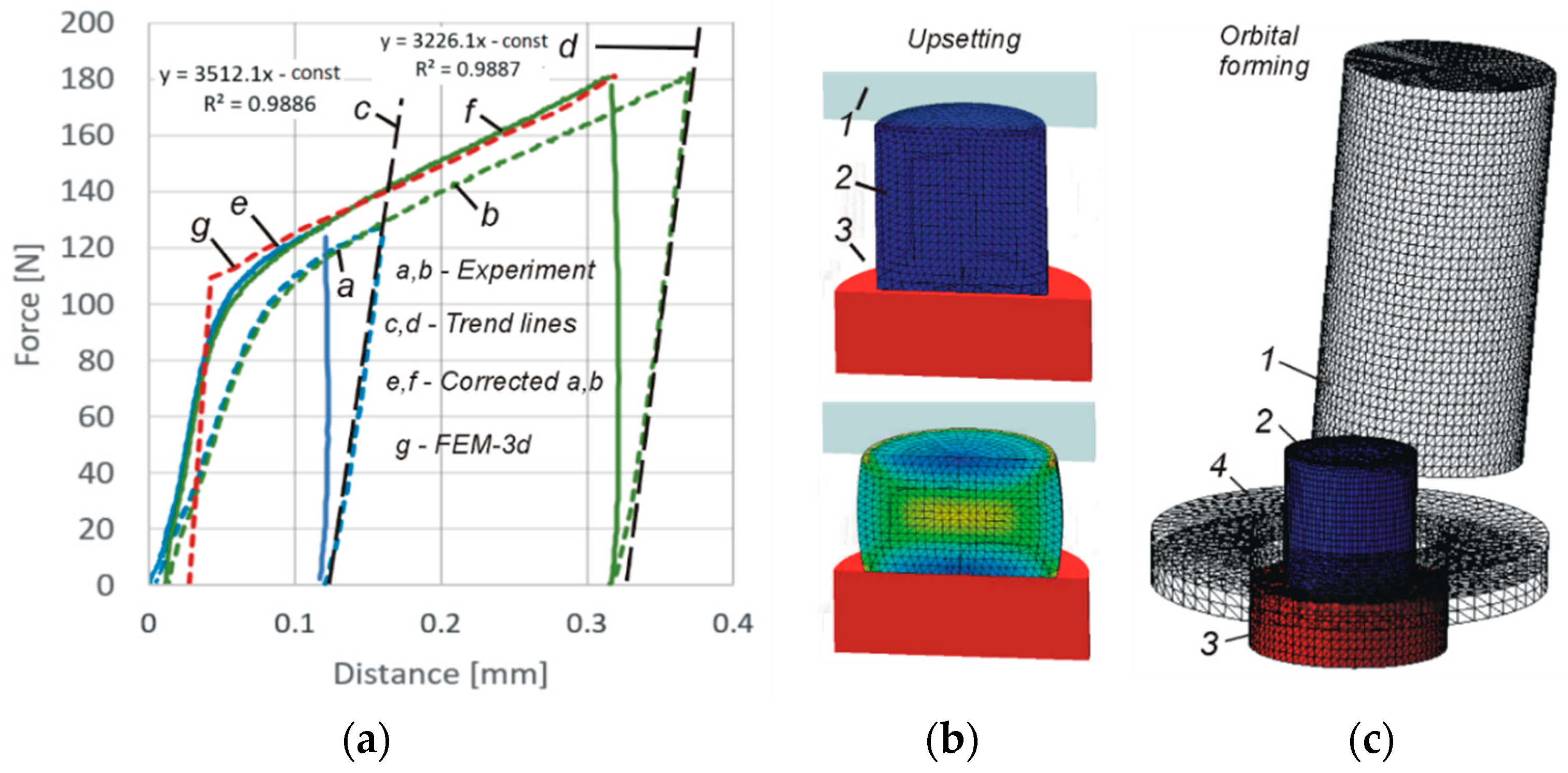
Figure 6.
Analysis of the video documentation of the UOM process: (a) Determination of punch position at the borders of the UOM phases; (b) Graphical interpretation of the process phases; and (c) Visualization of the process cycles.
Figure 6.
Analysis of the video documentation of the UOM process: (a) Determination of punch position at the borders of the UOM phases; (b) Graphical interpretation of the process phases; and (c) Visualization of the process cycles.

Figure 7.
FEM-3d modeling of orbital forming: (a) Process parameters; (b) Forces, where U is simple upsetting and Oa,b,c,d is orbital, as seen in rows A–D in (c); (c) Equivalent strain distribution; and (d) Contact area.
Figure 7.
FEM-3d modeling of orbital forming: (a) Process parameters; (b) Forces, where U is simple upsetting and Oa,b,c,d is orbital, as seen in rows A–D in (c); (c) Equivalent strain distribution; and (d) Contact area.
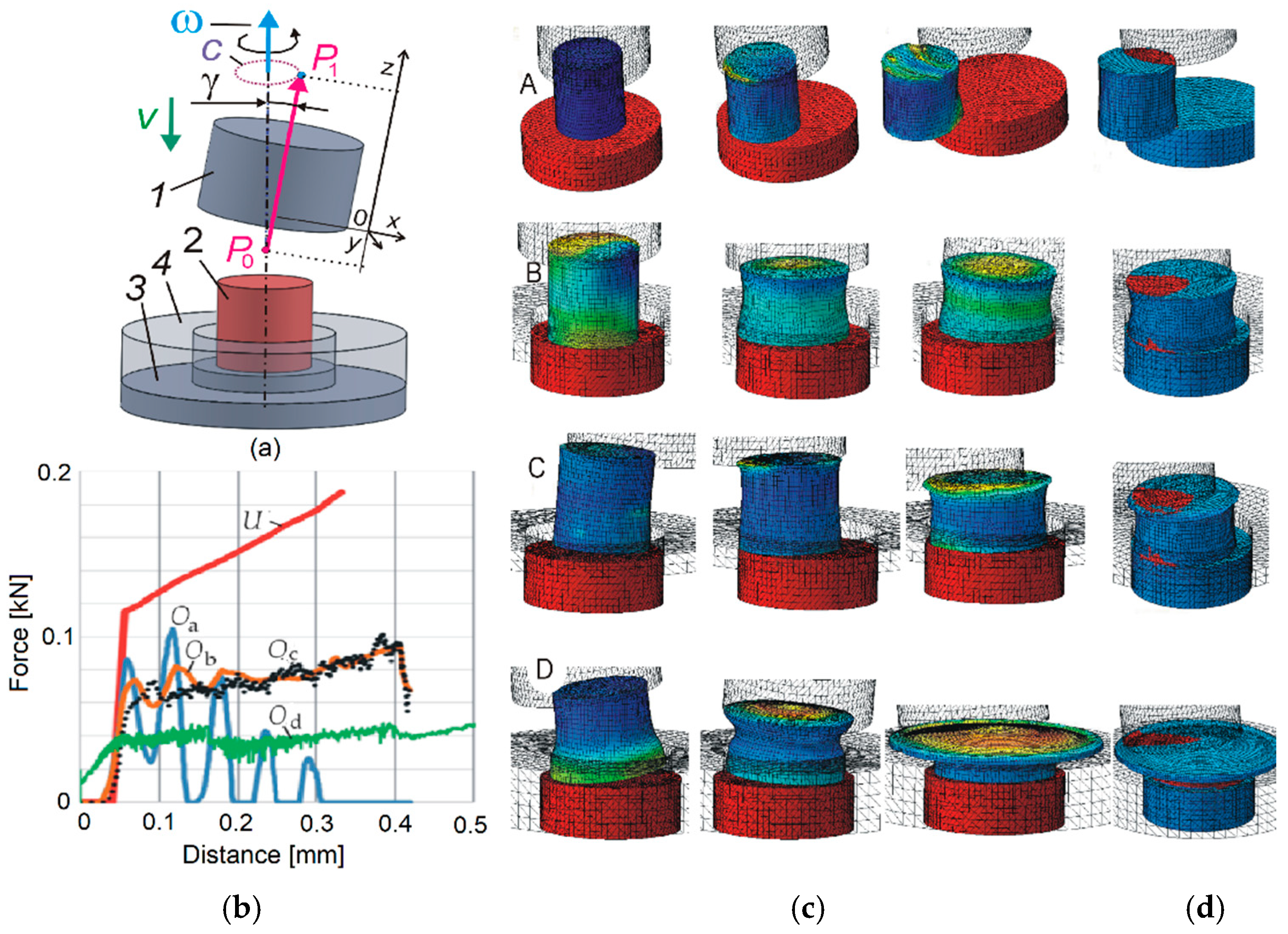
Figure 8.
The course and parameters of the UOM process: (a) end of the phase SF1/start of the phase SUOM; (b) phase SUOM; (c) end of the phase SUOM/start of the phase SF2; description in the text.
Figure 8.
The course and parameters of the UOM process: (a) end of the phase SF1/start of the phase SUOM; (b) phase SUOM; (c) end of the phase SUOM/start of the phase SF2; description in the text.


Table 1.
Mechanical properties of specimen materials.
| E (GPa) | Re (MPa) | ν (1) | C (MPa) | n (1) |
|---|---|---|---|---|
| 70 | 135 | 0.32 | 174 | 0.05 |
Table 2.
Ultrasonic orbital microforming (UOM) process parameters.
| Temp (°C) | Punch and Anvil (µm) | Ram vel. down (mm/min) | Ram vel. up (mm/min) | Lubricant | Ram Control | Vib. freq. (kHz) | Vib. amp. (μm) |
|---|---|---|---|---|---|---|---|
| 22 | Ra = 0.63 | 0.2 | 0.02 | Light oil | Stroke | 20 | 16 |
Table 3.
Punch kinematic parameters.
| Process | γ | ω | V | z0 | z1 |
|---|---|---|---|---|---|
| (orbital) | (deg) | (rpm) | (mm/s) | (mm) | (mm) |
| Oa | 4 | 6000 | 6 | −4 | 0 |
| Ob | 4 | 6000 | 6 | −4 | 0 |
| Oc | 4 | 6000 | 6 | −7.2 | 0 |
| Od | 8 | 800 | 0.2 | −2 | 0 |
© 2018 by the author. Licensee MDPI, Basel, Switzerland. This article is an open access article distributed under the terms and conditions of the Creative Commons Attribution (CC BY) license (http://creativecommons.org/licenses/by/4.0/).
Share and Cite
MDPI and ACS Style
Presz, W. Ultrasonic Orbital Microforming—A New Possibility in the Forming of Microparts. Metals 2018, 8, 889. https://doi.org/10.3390/met8110889
AMA Style
Presz W. Ultrasonic Orbital Microforming—A New Possibility in the Forming of Microparts. Metals. 2018; 8(11):889. https://doi.org/10.3390/met8110889
Chicago/Turabian StylePresz, Wojciech. 2018. "Ultrasonic Orbital Microforming—A New Possibility in the Forming of Microparts" Metals 8, no. 11: 889. https://doi.org/10.3390/met8110889
Note that from the first issue of 2016, this journal uses article numbers instead of page numbers. See further details here.