Article

Microstructure and Shear Strength of Brazing TiAl/Si3N4 Joints with Ag-Cu Binary Alloy as Filler Metal

1
Key Laboratory of Air-Driven Equipment Technology of Zhejiang Province, Quzhou University, Quzhou 324000, China
2
State Key Laboratory for Advanced Metals and Materials, University of Science and Technology Beijing, Beijing 410083, China
3
School of Materials Science and Engineering, Harbin University of Science and Technology, Harbin 150001, China
4
School of Mechanical and Automotive Engineering, Anhui Polytechnic University, Wuhu 241000, China
*
Authors to whom correspondence should be addressed.
Metals 2018, 8(11), 896; https://doi.org/10.3390/met8110896
Submission received: 17 October 2018 / Revised: 27 October 2018 / Accepted: 31 October 2018 / Published: 2 November 2018

Abstract

:
Vacuum brazing of TiAl intermetallic alloy to Si3N4 ceramics was performed using Ag-28Cu (wt.%) filler alloy. The brazing joints obtained at different brazing temperatures were studied in this work. The microstructure and the shear strength were analyzed in detail. The results show that the brazed joints could be divided into three regions: AlCu2Ti reaction layer near the Ti-48Al-2Cr-2Nb alloy, a typical Ag-Cu eutectic structure and a thin continuous TiN + Ti5Si3 reaction layer near the Si3N4 ceramics. The microstructure varied as the brazing temperature was increased from 1153 K/15 min to 1193 K/15 min. The shear strength of the joints first increased as the brazing temperature increased from 1153 K to 1173 K, and then decreased. The maximum shear strength reached 105.5 MPa at 1173 K/15 min and the mechanism was discussed.

1. Introduction

In the last decades, TiAl alloys have received considerable attention due to its higher specific strength, lower density and excellent creep resistance at elevated temperatures, which can be used as potential candidates for high temperature structural applications [1,2,3,4]. Recently, Ti-48Al-2Cr-2Nb blades have been used in commercial turbofan engines of General Electric Company [5,6,7]. However, due to the brittle nature and poor workability, fabricating large scale or complex-shaped components of TiAl alloys has many challenges [8,9,10].
To utilize the advantages of TiAl alloys, it is necessary to join small TiAl components to other materials. Recently, researchers have studied the vacuum brazing of TiAl alloys to ceramics. So far, various methods for ceramic-metal joining have been commonly used [11,12,13,14]. Compared with transient liquid phase bonding, diffusion bonding, etc., vacuum brazing is advanced in simplicity, lower cost and high quality [15,16]. Si3N4 ceramic is one of the most widely used ceramics in the thermal machine, heat exchangers, wear resistant elements and wave-transparent materials due to its excellent properties, such as light weight, high resistance to thermal shock, excellent creep resistance and wear properties [17,18,19]. When used as wave-transparent materials in antenna radomes, it would be brazed to a TiAl intermetallics holder. In fact, many factors would influence the brazing quality, such as the surface when used as chip resistors [20]. When used for structural applications, the quality of the surface has rarely been studied. However, up to now, the brazing of Si3N4 ceramics to Ti-48Al-2Cr-2Nb has rarely been reported.
It is well known that the filler metals play an important role in brazing ceramics to metals. Due to the low melting point and excellent wettability and ductility [21,22,23], the AgCu based filler alloy was effective in reducing the mismatch of the coefficients of thermal expansion. Correspondingly, the residual thermal stresses were reduced. So, AgCu based filler alloys have been widely used in brazing Si3N4 ceramics to metals.
In this work, an Ag-28Cu filler alloy was developed to braze the Si3N4 ceramics to a Ti-48Al-2Cr-2Nb alloy. The microstructure of the brazed joints was characterized by X-ray diffraction (XRD) and scanning electronic microscopy (SEM, Hitachi, Tokyo, Japan) equipped with energy disperse spectroscopy (EDS, Bruker, Karlsruhe, Germany). The joining properties are also studied.

2. Materials and Methods

Si3N4 ceramics used in this paper were hot pressed with Al2O3 additives. The metal partner used was TiAl intermetallic with composition of Ti-48Al-2Cr-2Nb (at.%). The Si3N4 ceramics and TiAl intermetallic was cut into blocks with the dimension of 4 mm × 4 mm × 4 mm and 10 mm × 10 mm × 4 mm, respectively. The Ag-28%Cu filler alloy used in this study was about 50 μm in thickness. Prior to joining, the brazing surfaces were ground on SiC grit papers and polished. All of the polished samples were ultrasonically cleaned by acetone. The Ag-Cu filler alloy was sandwiched between Si3N4 ceramic and Ti-48Al-2Cr-2Nb alloy specimens as shown in Figure 1a. A pressure of about 20 kPa was applied on the brazing assembly to ensure close contact of the surfaces by graphite blocks. The assembly was brazed in a vacuum of less than 2 × 10⁻³ Pa. The brazing processes were 1153 K/15 min, 1173 K/15 min and 1193 K/15 min, respectively.
The microstructure of the brazed joints was examined by SEM (Hitachi, Tokyo, Japan) equipped with EDS. A thin layer of gold was sprayed before the SEM examination. Subsequently, the SEM scans were carried out with the operation voltages of 15 kV. The phase analysis in the brazing seam was characterized by XRD. The XRD analysis was carried out on the surface of the shear test samples. The shear strength of the brazed joint was carried out on an Instron electronic universal testing machine (Instron, Boston, MA, USA), and the schematic illustration of the room temperature shear test is shown in Figure 1b. Five shear strength samples were tested to obtain the average shear strength.

3. Results and Discussion

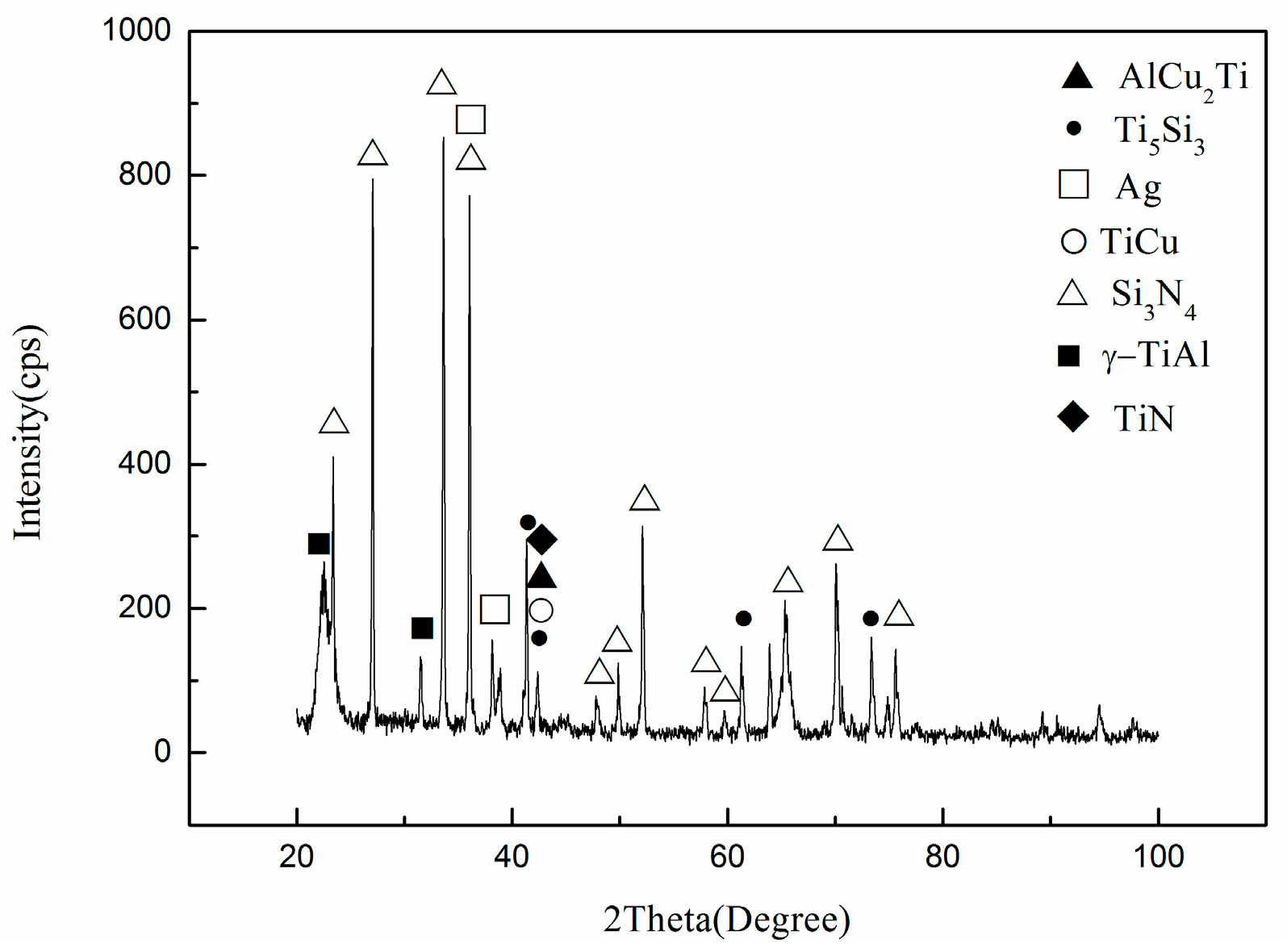
3.1. Microstructure of TiAl/AgCu/Si3N4 Joints

The typical cross-section of the Ti-48Al-2Cr-2Nb alloy and Si3N4 ceramic joint brazed with Ag-Cu filler metal at 1173 K is shown in Figure 2a. It can be seen obviously that a defect-free joint was formed between the base materials and the Ag-Cu filler alloy. The brazing joint can be divided into three characteristic regions, as marked in Figure 2a. It can be seen from Figure 2b–f, Ag, Cu, Ti and Al are the major elements in the brazing joint. The zone I is the Cu and Ti rich reaction layer near the Ti-48Al-2Cr-2Nb alloy, the zone II has typical Ag-Cu eutectic structure which can often be observed when ceramics were brazed by Ag-Cu-Ti filler alloy [24,25], where the bright phases are Ag-rich and the dark gray phases are Cu-rich. The zone III is the thin continuous reaction layer at the Si3N4 ceramic side.
The magnified images of the regions are given in Figure 3. The phases in the brazing joint were characterized by XRD and the results are shown in Figure 4. It can be seen that the γ-TiAl, Si3N4, Ag, AlCu2Ti, TiN and Ti5Si3 phase can be found in the brazing seam. The EDS is also employed to analyze the chemical compositions of the phases. The different phases in the brazing joint are specified as A–H respectively and the detected results and the possible phase are all listed in Table 1. As the XRD analysis was carried out on the surface of the shear test samples and a low volume fraction of phase constitution (less than 5%) may not be detected by XRD, the phase detected by XRD is different from those identified by EDS. The phases marked B, C, and D can be found in the interface between the Ti-48Al-2Cr-2Nb and the Ag-Cu filler (zone I). The white phase marked B is Ag(s,s) incorporating 75.1% Ag, 12.3%Cu, 6.0% Ti, 5.6% Al and 0.9% Cr, which is determined to be Ag(s,s). The atomic ratio of Al, Cu and Ti is about 1:2:1 in phase marked C. According to the Al-Ti-Cu phase diagram, it is AlCu2Ti phase. Additionally, the dissolution of the γ-TiAl in the Cu-Ag liquid phase will lead to the phase containing AlCu2Ti and Cu(s,s) precipitated during the solid process: L = AlCu2Ti + Cu(s,s), such as phase D. The chemical compositions of the bright phase marked E inside the brazing seam (zone II) can also be identified as Ag-rich. It can also be seen that there are many dark phases marked F formed in Ag(s,s). According to the EDS results, the phase is the Cu rich phase. The chemical composition result of phase G in zone III indicates that Ti atoms diffused to the interface next to the Si3N4 ceramics, and formed TiN + Ti5Si3 reaction layer via the reaction: 9Ti + Si3N4 = 4TiN + Ti5Si3. The Gibbs free energy of this reaction at 1173 K is −1297.945 kJ/mol (ΔGf (kJ/mol) = −1550.14 + 0.215T) [26], which confirms the compounds TiN and Ti5Si3 are both stable. The TiN + Ti5Si3 reaction layer can also be found other studies.
Figure 5 shows the SEM images of the TiAl/AgCu/Si3N4 joints brazed at different brazing temperatures for 15 min. It clearly demonstrates that the brazing joints also consisted of three zones: AlCu2Ti + Ag(s,s) layers (zone I), Ag(s,s) (zone II) and TiN + Ti5Si3 reaction layer (zone III). The thickness of the whole brazing joints is about 85 μm at 1153 K, 63 μm at 1173 K, 42 μm at 1193 K. The thickness of the brazing joints decreases with the increasing temperature. The main reason is that the molten filler metal would be expelled out of the brazing seam at higher brazing temperatures. It can be seen that the TiN + Ti5Si3 reaction layer thickened with increasing temperatures. When brazed at 1153 K, a macro-crack can be clearly seen in Figure 5a. It can also be found that the volume fraction of the Cu-rich phase in Ag(s,s), which is beneficial to strengthen to brazing seam, gets to the highest level at 1173 K. Further increasing the brazing temperature to 1173 K, the volume fraction of the continuous AlCu2Ti layer increases greatly and the volume fraction of the Cu-rich phase decreases.
From the analysis above, the formation mechanism of the TiAl/AgCu/Si3N4 brazed joints can be concluded. When the heating temperature reaches the melting point of the Ag-Cu filler alloy during brazing, it began to melt. Ti and Al would diffuse to the brazing seam. The AlCu2Ti layer would form at the TiAl side. At the same time, the Ti atom diffused to the Si3N4 side, which can react with Si3N4 to form TiN + Ti5Si3 reaction layer next to the Si3N4 side. When brazed at 1153 K/15 min, a macro-crack was generated in the brazing seam, which is caused by the lower flowability of the filler alloy. The diffusion rate is also lower, and then the volume fraction of Cu-rich phase in zone II is a bit higher. With increasing the brazing temperature to 1173 K, the macro-crack has disappeared due to higher flowability. Further increasing temperature to 1193 K, more Ti and Al will diffuse to the brazing seam and more Cu would diffuse to the TiAl side at higher brazing temperature, the volume fraction AlCu2Ti phase increases. The thickness of the brazing seam decreases with the increasing temperatures. The reduction was due to the expulsion of molten Ag-Cu filler alloy by capillarity out of the brazing seam at higher temperatures.

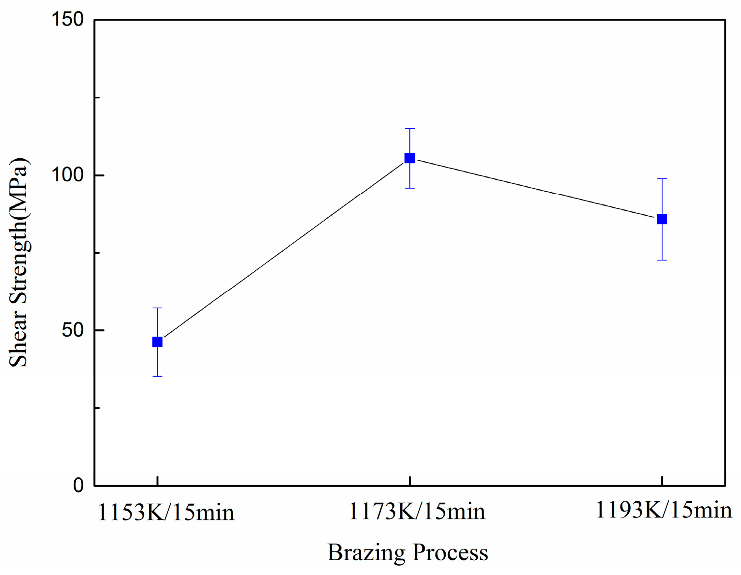
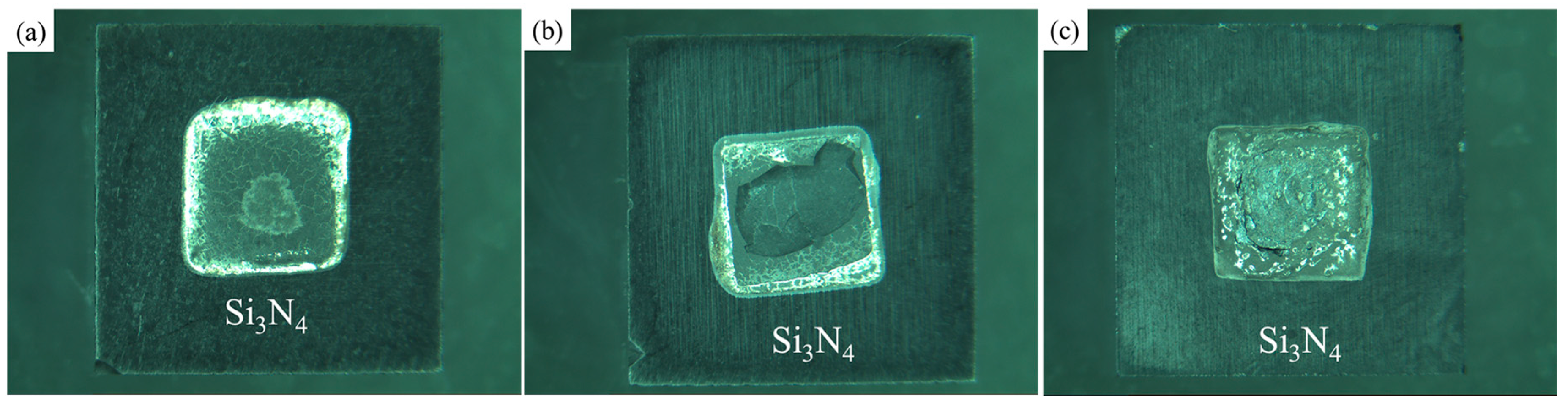
3.2. Mechanical Properties of TiAl/AgCu/Si3N4 Brazed Joints

Figure 6 shows the shear strength of the TiAl/AgCu/Si3N4 joints brazed at different temperatures. It can be seen that the highest shear strength was obtained at 1173 K/15 min. The shear strength is about 46.3 MPa at 1153 K, 105.5 MPa at 1173 K and 85.8 MPa at 1193 K. Vacuum brazing of the TiAl intermetallic alloy to Si3N4 ceramics was performed using Ag-Cu-Ti filler alloy in Song’s study [27]. The maximum shear strength is about 14.15 MPa. It can be clearly seen the maximum average shear strength is much higher than previous studies.
According to the microstructural analysis, the brazing seam was mainly composed of AlCu2Ti, Ag(s,s) and TiN + Ti5Si3 reaction layer. When brazed at 1153 K, the shear strength is a bit lower. The main reason is that the diffusion of element is incomplete at low brazing temperature. Macro-cracks were formed in the brazing seam, which can deteriorate the shear strength greatly. When the brazing temperature increases to 1173 K, the element would diffuse more intensively. The cracks have disappeared in the brazing seam. It can also be seen that more rich Cu phase was found in Ag(s,s), which can strengthen the brazing seam. All these lead to the increasing of shear strength. Further increasing temperature to 1193 K, the Ag(s,s) layer in zone II and the rich Cu phase in Ag(s,s) decreased, then the shear strength shows a slight decrease. Figure 7 shows the fracture modes of the TiAl/AgCu/Si3N4 joints. When brazed at 1153 K, the joint fractured along the brazing seam, as shown in Figure 7a. This fracture mode was formed mainly because the macro-defects were formed at 1153 K, the joints showed a weak bonding. When brazed at 1173 K and 1193 K, the fracture ruptured at the substrate, as shown in Figure 7b,c. The results showed that the residual stress was reduced when Ag-Cu filler alloy was used.

4. Conclusions

TiAl intermetallic alloy and Si3N4 ceramics were successfully brazed by the Ag-Cu filler alloy. The microstructure and shear strength of the brazed joint at different brazing processes were investigated. The primary conclusions are summarized as follows:
(1) A sound joint without cracks or voids can be formed between the base materials and the Ag-Cu filler alloy. The brazing joints consist of three zones: AlCu2Ti reaction layer, Ag(s,s) and TiN + Ti5Si3 reaction layer. The typical microstructure of the brazing joints is the AlCu2Ti, Ag(s,s), Cu rich phase, TiN and Ti5Si3 phase.
(2) As the brazing temperatures increases, the thickness of the whole brazing joints decreases which is attributed to the fact that the molten filler metal would be expelled out of the brazing seam at higher brazing temperatures. The reaction layer of TiN + Ti5Si3 also thickened with increasing brazing temperatures. When brazed at 1153 K, a macro-crack was generated in the brazing seam, which is caused by the lower flowability of the Ag-Cu filler alloy. At 1193 K, a few micro-cracks can be found in the brazing seam. A defect-free joint was obtained at 1173 K.
(3) As the brazing temperatures increases, the shear strength first increased and then decreased. The maximal shear strength of the joints reached 105.5 MPa at 1173 K. Macro- and micro-cracks and the Cu-rich phase can influence the shear strength greatly.

Author Contributions

D.D., D.Z. and G.W. conducted the experiments. D.D., D.Z. and Y.W. wrote the article. P.W. and Q.H. cooperated in the experiments.

Funding

This work was supported by the National Natural Science Foundation of China (Grant No. 51501100, 51801112, 51704001), the Zhejiang Provincial Natural Science Foundation of China (Grant No. Y18E010014).

Conflicts of Interest

The authors declare no conflict of interest.

References

  1. Yang, J.R.; Chen, R.R.; Ding, H.A.; Guo, J.J. Heat transfer and macrostructure formation of Nb containing TiAl alloy directionally solidified by square cold crucible. Intermetallics 2013, 42, 184–191. [Google Scholar] [CrossRef]
  2. Zhu, D.D.; Dong, D.; Ni, C.Y.; Zhang, D.F. Effect of wheel speed on the microstructure and nanohardness of rapidly solidified Ti-48Al-2Cr alloy. Mater. Caract. 2015, 99, 243–247. [Google Scholar] [CrossRef]
  3. Yang, J.R.; Wang, X.Y.; Cao, B.; Wu, Y.L.; Zhang, K.R. Tailoring the Microstructure of a β-Solidifying TiAl Alloy by Controlled Post-solidification Isothermal Holding and Cooling. Metall. Mater. Trans. A 2017, 48, 5095–5105. [Google Scholar] [CrossRef]
  4. Ding, J.; Zhang, M.H.; Liang, Y.F.; Ren, Y. Enhanced high-temperature tensile property by gradient twin structure of duplex high-Nb-containing TiAl alloy. Acta Mater. 2018, 161, 1–11. [Google Scholar] [CrossRef]
  5. Mohsen, S.; Ayman, A.S.; Daniel, P.S.; Ulf, A.; John, J.L. Effects of HIP on microstructural heterogeneity, defect distribution and mechanical properties of additively manufactured EBM Ti-48Al-2Cr-2Nb. J. Alloys Compd. 2017, 729, 1118–1135. [Google Scholar]
  6. Ken, C.; Ryota, K.; Jong, Y.O.; Hiroyuki, Y.Y.; Masao, T. Influence of unique layered microstructure on fatigue properties of Ti-48Al-2Cr-2Nb alloys fabricated by electron beam melting. Intermetallics 2018, 95, 1–10. [Google Scholar]
  7. Sunderkotter, J.D.; Schmutzler, H.J.; Haanappei, V.A.C.; Hofman, R.; Stroosnijder, M.F. The high-temperature oxidation behaviour of Ti-47Al-2Cr-0.2Si and Ti-48Al-2Cr-2Nb compared with Ti-48Al-2Cr. Intermetallics 1997, 5, 525–534. [Google Scholar] [CrossRef]
  8. Schwaighofer, E.; Clmens, H.; Mayer, S.; Lindemann, J. Microstructural design and mechanical properties of a cast and heat-treated intermetallic multi-phase γ-TiAl based alloy. Intermetallics 2014, 44, 128–140. [Google Scholar] [CrossRef]
  9. Goral, M.; Swadzba, L.; Moskal, G.; Jarczyk, G.; Aguilar, J. Diffusion aluminide coatings for TiAl intermetallic turbine blades. Intermetallics 2011, 19, 744–747. [Google Scholar] [CrossRef]
  10. Nikitina, M.A.; Islamgaliev, R.K.; Sitdikov, V.D. Thermal stability of TiAl-based intermetallic alloys subjected to high pressure torsion. Mater. Sci. Eng. A 2016, 651, 306–310. [Google Scholar] [CrossRef]
  11. Dong, D.; Zhu, D.D.; Zheng, H.X.; Wang, G. Brazing TiC/Ti matrix composite using TiNi eutectic braze alloy. Vacuum 2018, 156, 411–418. [Google Scholar] [CrossRef]
  12. Zhang, S.Y.; Yuan, Y.; Su, Y.Y.; Song, X.R. Interfacial microstructure and mechanical properties of brazing carbon/carbon composites to stainless steel using diamond particles reinforced Ag-Cu-Ti brazing alloy. J. Alloys Compd. 2017, 719, 108–115. [Google Scholar] [CrossRef]
  13. Song, X.R.; Li, H.J.; Zeng, X.R.; Zhang, L.L. Brazing of C/C composites to Ti6Al4V using graphene nanoplatelets reinforced TiCuZrNi brazing alloy. Mater. Lett. 2016, 183, 232–235. [Google Scholar] [CrossRef]
  14. Cheniti, B.; Miroud, D.; Badji, R.; Allou, D. Effect of brazing current on microstructure and mechanical behavior of WC-Co/AISI 1020 steel TIG brazed joint. Int. J. Refract. Met. Hard Metar. 2017, 64, 210–218. [Google Scholar] [CrossRef]
  15. Osipv, V.V.; Luckyashin, K.E.; Shitov, V.A.; Maksimov, R.N. Two-step thermal diffusional bonding of transparent Nd:YAG ceramics. Mater. Lett. 2016, 167, 81–84. [Google Scholar] [CrossRef]
  16. Tan, C.W.; Yang, J.Y.; Zhao, X.Y. Influence of Ni coating on interfacial reactions and mechanical properties in laser welding-brazing of Mg/Ti butt joint. J. Alloys Compd. 2018, 764, 186–201. [Google Scholar] [CrossRef]
  17. Saivo, M.; Casaiegno, V.; Suess, M.; Gozzelin, L.; Wilhelmi, C. Laser surface nanostructuring for reliable Si3N4/Si3N4 and Si3N4/Invar joined components. Ceram. Int. 2018, 44, 12081–12087. [Google Scholar]
  18. Martinavicius, A.; Van, H.P.; Danoix, R.; Redjaimia, A.; Danoix, F. Mechanism of Si3N4 precipitation in nitrided Fe-Si alloys: A novel example of particle-stimulated-nucleation. Mater. Lett. 2017, 189, 25–27. [Google Scholar] [CrossRef]
  19. Kgoete, F.M.; Popoola, A.P.I.; Fayomi, O.S.I.; Adebiyi, I.D. Influence of Si3N4 on Ti-6Al-4V via spark plasma sintering: Microstructure, corrosion and thermal stability. J. Alloys Compd. 2018, 763, 322–328. [Google Scholar] [CrossRef]
  20. Collins, M.N.; Punch, J. Surface finish effect on reliability of SAC 305 soldered chip resistors. Solder Surf. Mt. Technol. 2012, 24, 240–248. [Google Scholar] [CrossRef]
  21. Zhao, Y.X.; Song, X.G.; Tan, C.W.; Hu, S.P.; Feng, J.C. Microstructural evolution of Si3N4/Ti6Al4V joints brazed with nano-Si3N4 reinforced AgCuTi composite filler. Vacuum 2017, 142, 58–65. [Google Scholar] [CrossRef]
  22. Liu, M.X.; Liu, C.F.; Zhang, J.; Tao, R.; Qi, Q. Microstructure and mechanical properties of BN-Si3N4 and AlON joints brazed with Ag-Cu-Ti filler alloy. J. Eur. Ceram. Soc. 2018, 38, 1265–1270. [Google Scholar] [CrossRef]
  23. Paulasto, M.; Kivilahti, J.K. Formation of interfacial microstructure in brazing of Si3N4 with Ti-activated Ag-Cu filler alloys. Scr. Metall. Mater. 1995, 32, 1209–1214. [Google Scholar] [CrossRef]
  24. Dai, X.Y.; Cao, J.; Liu, J.K.; Su, S.; Feng, J.C. Effect of holding time on microstructure and mechanical properties of ZrO2/TiAl joints brazed by Ag–Cu filler metal. Mater. Des. 2015, 87, 53–59. [Google Scholar] [CrossRef]
  25. Yang, Z.W.; He, P.; Zhang, L.X.; Feng, J.C. Microstructural evolution and mechanical properties of the joint of TiAl alloys and C/SiC composites vacuum brazed with Ag–Cu filler metal. Mater. Charact. 2011, 62, 825–832. [Google Scholar] [CrossRef]
  26. Liu, C.F.; Zhang, J.; Zhou, Y.; Meng, Q.C.; NaKa, M. Effect of Ti content on microstructure and strength of Si3N4/Si3N4 joints brazed with Cu-Pd-Ti filler metals. Mater. Sci. Eng. A 2008, 491, 483–487. [Google Scholar] [CrossRef]
  27. Song, X.G.; Zhao, Y.X.; Hu, S.P.; Cao, J.; Feng, J.C. Wetting of AgCu-Ti filler on porous Si3N4 ceramic and brazing of the ceramic to TiAl alloy. Ceram. Int. 2018, 44, 4622–4629. [Google Scholar] [CrossRef]
Figure 1. Schematic drawing of: (a) Brazing assembly; (b) shear test.
Metals 08 00896 g001
Figure 2. Elemental analysis results of the TiAl/AgCu/Si3N4 joints brazed at 1173 K. (a) Interfacial microstructure; (bf) element distribution images of Ag, Cu, Ti, Al and Si.
Metals 08 00896 g002
Figure 3. Scanning electron microscopy (SEM) image of the joint interface brazed at 1173 K for 15 min. (a) Magnification image of zone I and II; (b) magnification image of zone III.
Metals 08 00896 g003
Figure 4. X-ray diffraction (XRD) results of the fracture surfaces brazed at 1173 K.
Metals 08 00896 g004
Figure 5. The interfacial microstructures of TiAl/AgCu/Si3N4 brazed joints at different brazing temperatures. (a) 1153 K, (b) 1173 K, (c) 1193 K.
Metals 08 00896 g005
Figure 6. Effect of brazing temperature on the shear strength of TiAl/AgCu/Si3N4 brazed joints.
Metals 08 00896 g006
Figure 7. Fracture modes of TiAl/AgCu/Si3N4 joint brazed at different temperatures. (a) 1153 K, (b) 1173 K, (c) 1193 K.
Metals 08 00896 g007
Table 1. Chemical analysis (at.%) of the phases marked in Figure 3.
PhaseAlTiAgCuSiNNbCrPossible Phase
A48.049.6----1.41.0γ-TiAl
B5.66.075.112.3--0.10.9Ag-rich
C23.526.60.647.4--0.81.1AlCu2Ti
D8.47.722.459.7--0.51.3AlCu2Ti + Cu(s,s)
E4.83.871.313.52.03.20.41.0Ag-rich
F24.60.521.651.50.1-0.51.2Cu rich phase
G0.259.44.72.315.617.50.10.2TiN + Ti5Si3
H5.33.21.01.152.935.10.31.1Si3N4

