Feedstocks of Aluminum and 316L Stainless Steel Powders for Micro Hot Embossing


Abstract
:1. Introduction
2. Materials and Methods
3. Results and Discussion
3.1. Optimization Process: Effects of Powder Type
3.2. Feedstocks: Effect of Composition on Torque Values
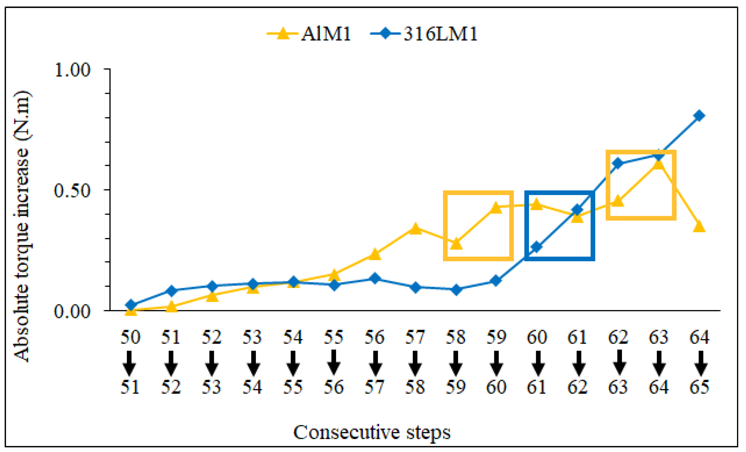
3.3. Feedstocks, Torque Stability and Homogeneity
3.4. Shaping Feedstocks
4. Conclusions
Author Contributions
Funding
Acknowledgments
Conflicts of Interest
References
- Peng, L.F.; Deng, Y.J.; Yi, P.Y.; Lai, X.M. Micro hot embossing of thermoplastic polymers: A review. J. Micromech. Microeng. 2014, 24. [Google Scholar] [CrossRef]
- Heckele, M.; Bacher, W.; Muller, K.D. Hot embossing—The molding technique for plastic microstructures. Microsyst. Technol. 1998, 4, 122–124. [Google Scholar] [CrossRef]
- Fu, G.; Tor, S.; Loh, N.; Hardt, D. Micro-hot-embossing of 316L stainless steel micro-structures. Appl.Phys. A: Mater. Sci. Process. 2009, 97, 925–931. [Google Scholar] [CrossRef]
- Sequeiros, E.W.; Neto, V.C.; Vieira, M.T.; Vieira, M.F. Hot micro-embossing: Effect of pressure on 316L metal parts. Powder Metall. 2014, 57, 241–244. [Google Scholar] [CrossRef]
- Sahli, M.; Millot, C.; Gelin, J.C.; Barrière, T. The manufacturing and replication of microfluidic mould inserts by the hot embossing process. J. Mater. Process. Technol. 2013, 213, 913–925. [Google Scholar] [CrossRef]
- Sahli, M.; Millot, C.; Gelin, J.C.; Barrière, T. Development and characterization of polymers-metallic hot embossing process for manufacturing metallic micro-parts. AIP Conf. Proc. 2011, 1315, 677–682. [Google Scholar] [CrossRef]
- Sahli, M.; Gelin, J.C.; Barriere, T. Characterisation and replication of metallic micro-fluidic devices using three different powders processed by hot embossing. Powder Technol. 2013, 246, 284–302. [Google Scholar] [CrossRef] [Green Version]
- Barreiros, F.M.; Vieira, M.T. PIM of non-conventional particles. Ceram. Int. 2006, 32, 297–302. [Google Scholar] [CrossRef]
- Hausnerova, B.; Mukund, B.N.; Sanetrnik, D. Rheological properties of gas and water atomized 17-4PH stainless steel MIM feedstocks: Effect of powder shape and size. Powder Technol. 2017, 312, 152–158. [Google Scholar] [CrossRef]
- Bakshi, S.R.; Lahiri, D.; Agarwal, A. Carbon nanotube reinforced metal matrix composites—A review. Int. Mater. Rev. 2010, 55, 41–64. [Google Scholar] [CrossRef]
- Ye, H.Z.; Liu, X.Y.; Hong, H.P. Fabrication of metal matrix composites by metal injection molding—A review. J. Mater. Process. Technol. 2008, 200, 12–24. [Google Scholar] [CrossRef] [Green Version]
- Romero, A.; Herranz, G. Development of feedstocks based on steel matrix composites for metal injection moulding. Powder Technol. 2017, 308, 472–478. [Google Scholar] [CrossRef]
- Supati, R.; Loh, N.; Khor, K.; Tor, S. Mixing and characterization of feedstock for powder injection molding. Materials Letters 2000, 46, 109–114. [Google Scholar] [CrossRef]
- Barreiros, F.M.; Vieira, M.T.; Castanho, J.M. Fine tuning injection feedstock by nano coating SS powder. Met. Powder Rep. 2009, 64, 18–21. [Google Scholar] [CrossRef]
- Emadinia, O.; Vieira, M.F.; Vieira, M.T. Effect of Reinforcement Type and Dispersion on the Hardening of Sintered Pure Aluminium. Metals 2018, 8, 786. [Google Scholar] [CrossRef]
- Enneti, R.K.; Onbattuvelli, V.P.; Atre, S.V. Powder binder formulation and compound manufacture in metal injection molding (MIM). In Handbook of Metal Injection Molding; Woodhead Publishing: Cambridge, UK, 2012; pp. 64–92. [Google Scholar]
- Sequeiros, E.W. Microfabricação de Componentes Metálicos por Microgravação. PhD Thesis, University of Porto, Porto, Portugal, July 2014. [Google Scholar]
- Sotomayor, M.; Várez, A.; Levenfeld, B. Influence of powder particle size distribution on rheological properties of 316L powder injection moulding feedstocks. Powder Technol. 2010, 200, 30–36. [Google Scholar] [CrossRef]
- Kong, X.; Barriere, T.; Gelin, J. Determination of critical and optimal powder loadings for 316L fine stainless steel feedstocks for micro-powder injection molding. J. Mater. Process. Technol. 2012, 212, 2173–2182. [Google Scholar] [CrossRef]
- Park, S.J.; Kim, D.; Lin, D.; Park, S.J.; Ahn, S. Rheological Characterization of Powder Mixture Including a Space Holder and Its Application to Metal Injection Molding. Metals 2017, 7, 120. [Google Scholar] [CrossRef]
- Ferreira, T.J.; Vieira, M.T. Optimization of MWCNT—Metal Matrix Composites feedstocks. Cienc. Tecnol. Mater. 2017, 29, e87–e91. [Google Scholar] [CrossRef]
- Ferreira, T.J.; Vieira, M.T. Behaviour of feedstocks reinforced with nanotubes for micromanufacturing. In Proceedings of the Euro PM 2014 Congress and Exhibition, Salzburg, Austria, 21–24 September 2014; Available online: https://www.epma.com/publications/euro-pm-proceedings/product/euro-pm2014-powder-injection-moudling-modelling-and-processing (accessed on 27 November 2018).
- Ahmad, F.; Muhsan, A.S.; Raza, M.R. Rheological behavior of carbon nanotubes/copper feedstocks for metal injection molding. Adv. Mater. Res. 2012, 403–408, 5335–5340. [Google Scholar] [CrossRef]
- Liang, S.; Tang, Y.; Zhang, Y.; Zhong, J. The rheologyical effect of carbon nanotubes on the iron based metal powder injection molding feedstock. Adv. Mater. Res. 2009, 79–82, 469–472. [Google Scholar] [CrossRef]
- Gonzalez-Gutierrez, J.; Duretek, I.; Kukla, C.; Poljsak, A.; Bek, M.; Emri, I.; Holzer, C. Models to Predict the Viscosity of Metal Injection Molding Feedstock Materials as Function of Their Formulation. Metals 2016, 6, 129. [Google Scholar] [CrossRef]
- Li, Y.M.; Liu, X.Q.; Luo, F.H.; Yue, J.L. Effects of surfactant on properties of MIM feedstock. Trans. Nonferr. Met. Soc. China 2007, 17, 1–8. [Google Scholar] [CrossRef]
- Sahli, M.; Gelin, J.C. Development of a feedstock formulation based on polypropylene for micro-powder soft embossing process of 316L stainless steel micro-channel part. Int. J. Adv. Manuf. Technol. 2013, 69, 2139–2148. [Google Scholar] [CrossRef] [Green Version]
- Nuriel, S.; Liu, L.; Barber, A.H.; Wagner, H.D. Direct measurement of multiwall nanotube surface tension. Chem. Phys. Lett. 2005, 404, 263–266. [Google Scholar] [CrossRef]
- Ahn, S.; Park, S.J.; Lee, S.; Atre, S.V.; German, R.M. Effect of powders and binders on material properties and molding parameters in iron and stainless steel powder injection molding process. Powder Technol. 2009, 193, 162–169. [Google Scholar] [CrossRef]
- Spitalsky, Z.; Tasis, D.; Papagelis, K.; Galiotis, C. Carbon nanotube-polymer composites: Chemistry, processing, mechanical and electrical properties. Progress Polym. Sci. 2010, 35, 357–401. [Google Scholar] [CrossRef]


| Material | Supplier | D50 (µm) | Density (kg/m3) | Specific Surface Area (m2/kg) 1 | Aspect Ratio |
|---|---|---|---|---|---|
| AISI 316L | Sandvik Osprey Ltd 2 | 3.5 | 7937 | 2120 | ~1 |
| Al | Alfa Aesar 3 | 10.0 | 2670 | 695 | >1 |
| MWCNT | Fibermax Composites 4 | - | 2010 | - | |
| M1 | Atect® Corporation 5 | - | 970 | - |
| Die | Diameter | Height | Maximum Width | Minimum Width | Sa | Sz |
|---|---|---|---|---|---|---|
| Dark blue elastomer | 4918 | ~<400 | - | - | 2 | 36 |
| Transparent elastomer | 4896 | 355 ± 9 | 326 ± 10 | 204 ± 13 | 9 | 680 6 |
| Acronym | Constituents | Concentration (vol.%) | Torque (Nm) | Standard Deviation |
|---|---|---|---|---|
| Al58M1 | Al & M1 | 58:42 | 2.66 | 0.06 |
| Al-MWCNT58M1 | Al, CNT & M1 | 58(1):42 | 3.92 | 0.04 |
| Al-MWCNT58M1SA5 | Al, CNT, M1 & SA | 58(1):42(5) | 1.97 | 0.07 |
| Al62M1 | Al & M1 | 62:38 | 3.63 | 0.08 |
| Al62M1SA1.6 | Al, M1 & SA | 62:38(1.6) | 2.00 | 0.05 |
| Al62M1SA5 | Al, M1 & SA | 62:38(5) | 1.58 | 0.04 |
| Al65M1 | Al & M1 | 65:35 | 5.05 | 0.13 |
| 316L60M1 | 316L & M1 | 60:40 | 2.76 | 0.05 |
| 316L-MWCNT60M1 | 316L, CNT & M1 | 60(1):40 | 3.79 | 0.07 |
| 316L65M1 | 316L & M1 | 65:35 | 5.06 | 0.09 |
| Part | Diameter | Height | Maximum Width | Minimum Width | Sa | Sz |
|---|---|---|---|---|---|---|
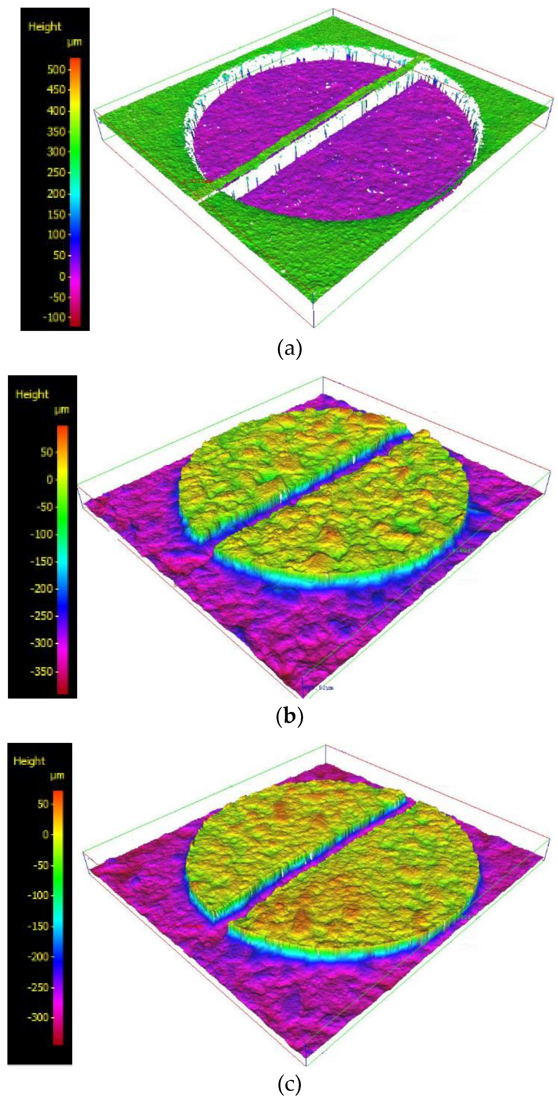
| Used elastomer die in Figure 12a | 4870 | 324 ± 10 | 347 ± 21 | 248 ± 12 | 6 | 106 |
| Green part in Figure 12b | 4856 | 266 ± 6 | 403 ± 14 | 246 ± 12 | 17 | 161 |
| Green part in Figure 12c | 4843 | 271 ± 54 | 362 ± 33 | 283 ± 27 | 13 | 107 |
© 2018 by the authors. Licensee MDPI, Basel, Switzerland. This article is an open access article distributed under the terms and conditions of the Creative Commons Attribution (CC BY) license (http://creativecommons.org/licenses/by/4.0/).
Share and Cite
Emadinia, O.; Vieira, M.T.; Vieira, M.F. Feedstocks of Aluminum and 316L Stainless Steel Powders for Micro Hot Embossing. Metals 2018, 8, 999. https://doi.org/10.3390/met8120999
Emadinia O, Vieira MT, Vieira MF. Feedstocks of Aluminum and 316L Stainless Steel Powders for Micro Hot Embossing. Metals. 2018; 8(12):999. https://doi.org/10.3390/met8120999
Chicago/Turabian StyleEmadinia, Omid, Maria Teresa Vieira, and Manuel Fernando Vieira. 2018. "Feedstocks of Aluminum and 316L Stainless Steel Powders for Micro Hot Embossing" Metals 8, no. 12: 999. https://doi.org/10.3390/met8120999