Abstract
Tensile and impact properties of API 5L X80 steel were investigated and compared in order to evaluate their relation. Yield and maximum forces under dynamic impact testing were obtained from force-displacement curves. Dynamic yield strength was estimated using the von Mises yield criterion. A different approach was taken in order to estimate the dynamic tensile strength; the instrumented RKP 450 Zwick/Roell machine was used for this specific purpose. From the 10-mm-thick steel plate, Charpy V notch (CVN) samples were cut off in longitudinal orientation considering the rolling direction. For this research, CVN specimens were machined according to the ISO 148:2016 standard. Tensile specimens were machined according to the ISO 6892-1:2016 standard. It was found that the results between the tensile and impact properties were very close and within 5%.
1. Introduction
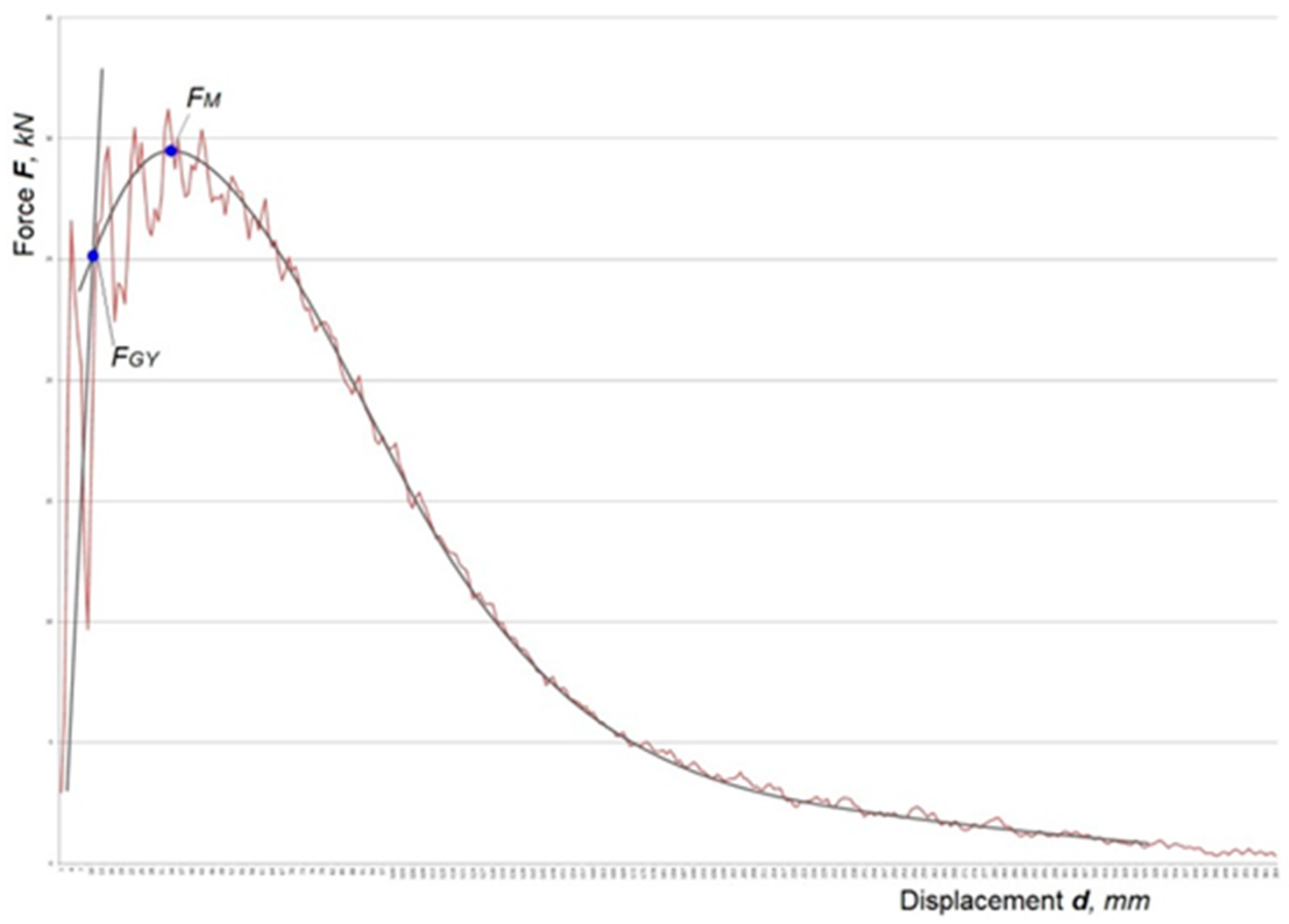
Since it was first introduced in material testing, the Charpy impact testing method has provided significant information about the behavior of material under impact conditions. Throughout history, the classic and instrumented methods have significantly improved, although there is still a wide range of unknowns that need to be solved—which is especially the case for the instrumented method [1,2]. Accurate measurement of displacement and force because of the high oscillations which occur during the testing on the force-displacement diagram is one of those unknowns (see Figure 1) [3]. Alongside the physical values, there are also difficulties in evaluating the mechanical properties from the data obtained from the impact testing machine. In this work, the authors propose a method for estimating the dynamic tensile strength. An important issue in industry today is the need to reduce the costs of material testing. The driving force behind this research was the idea of whether there was a way to only use a single method—the instrumented Charpy, in order to obtain mechanical property values that are usually obtained by another method—with the aim of reducing time and expense. The purpose of this paper was to establish a connection between certain mechanical properties obtained by the instrumented impact and tensile tests, including the constraint factor values calculated at the maximum force. In published papers, the connection between impact and tensile tests have been referred to as the yield strength, where the constraint factor is well known [4,5,6]. During this investigation, tensile and instrumented impact Charpy tests were carried out and mechanical properties were estimated at the yield and maximum force.
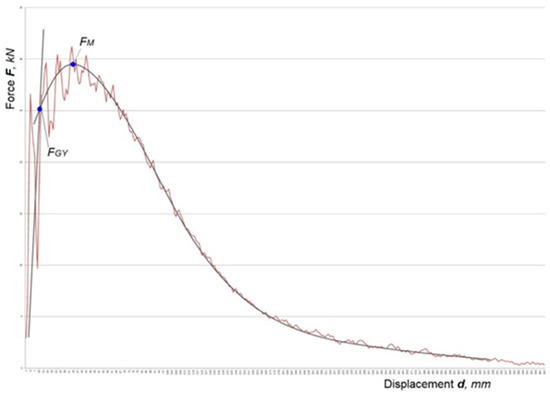
Figure 1.
Force-displacement diagram with the elastic slope and curve fitted to the remaining part of the diagram.
2. Background
The typical force-displacement diagram for ductile steel materials is shown in Figure 1. From the force-time or force-displacement diagram obtained from instrumented impact testing, the yield force should be estimated by fitting the slope to the elastic part of the curve. The elastic part of the slope consists of the elastic compliances of the specimen and machine. To estimate the maximum force, the curve should be fitted to the general yield part of the diagram. The intersection of these two curves yields the .
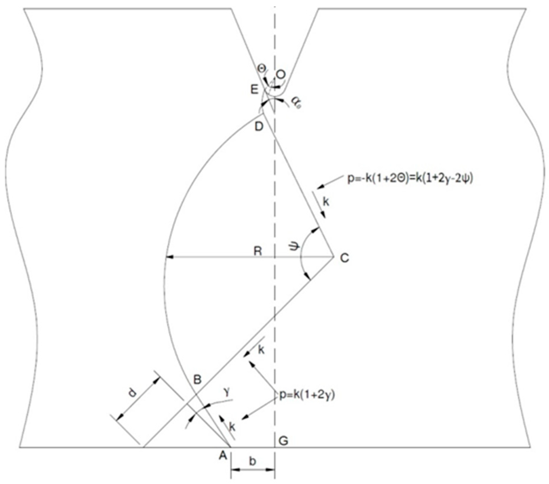
In Figure 1, is the maximum force and is the yield force. To estimate the yield strength, the slip-line solution was introduced. Kotter proposed the theory in 1903, which was later developed by Prandtl in 1920, where he introduced the slip-line solution for plastic-rigid bodies [7]. The solution was later developed by Hencky, Hill, Prager et al. To calculate yield strength under dynamic loading, it is essential to calculate the constraint factor, f. Green calculated the constraint factor, f, during pure bending with a notch consisting of a vanishingly small root radius of r ≈ 0 mm, which is shown clearly in [8]. Green and Hundy calculated f under three-point bending with a 45° notch and a vanishingly small root radius of r ≈ 0 mm [9]. Lianis and Ford introduced a general solution to calculate f for different types of notches [10]. Alexander and Komoly used CVN samples in their work [11], but they did not include the striker radius in their calculations. To estimate the constraint factor, Ewing [12] included the striker radius. The standard ISO striker has a radius of 2 mm. According to Alexander and Komoly, Ewing replaced the radius of the striker with a flat-topped punch with a width of 2b and analyzed the slip-line field. In Figure 2, Ewing’s schematic slip-line field is presented.
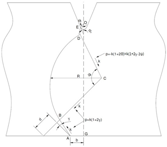
Figure 2.
One half of the plain strain slip-line field, reproduced from [12], with permission of Elsevier, 1968.
3. Estimation of Dynamic Mechanical Properties
In order to estimate the dynamic yield strength, , the constraint factor, f, is introduced. By R. Hill’s definition, the constraint factor is the factor by which the mean axial stress in the minimum section exceeds the true yield stress of 2k and is greatest when the notch has parallel sides [13]. For a CVN notch with the ISO striker radius, the value of the constraint factor is equal to 1.274 [12]. To calculate the constraint factor, the next equation is introduced [9]:
where the M is the yield-point moment, W is the specimen width, and a is the depth of the notch.
The bending moment M at the general yield (for span to width ratio of 4) is equal to (2) [14].
By introducing the ISO 148:2016 designations, W and B are the width and thickness of the CVN specimen.
For the purpose of calculating the dynamic yield strength, the von Mises yield criterion is used (3),
where is the yield strength of the material in pure shear. If we substitute k for in Equation (1), then it is easy to derive the equation for the dynamic yield strength from Equations (1) and (3) [14].
Replacing in Equation (4) with Equation (2), we can calculate:
After introducing the constraint factor, f, we can include the parameter , which is defined by [4]:
Equation (6) will become:
To estimate the dynamic tensile strength, , it is essential to know the value of the constraint factor. An attempt to derive the value of the constraint factor at maximum force is introduced in this paper by the authors. The reason for this is that in available literature, its value has not been found. Also, it is questionable to use the von Mises yield criterion. According to R. Hill, the constraint factor should decrease as the bending of the specimen increases, i.e., the constraint factor rises steadily from the value unity with increasing a/r ratio, where r is notch radius [13]. With a vanishingly small root radius (r/a ⟶ 0), the constraint factor increases [9,11,12]. However, if we include the width of the striker, as suggested in [11], the value of the constraint factor rises as the bending of the Charpy specimen increases. The constraint factor at maximum force was estimated using Ewing’s six equations, which were introduced in [12].
Using to Ewing’s six equations [12], it was attempted to estimate the constraint factor, f, at the maximum force value. The average value of the constraint factor for all specimens in longitudinal rolling direction is given in Table 1. After the estimation of the constraint factor, an equation for the dynamic tensile strength was developed based on the procedure for dynamic yield strength. According to the common approximate value of the ratio between tensile shear strength and tensile strength of 0.75 [4], the following equation was derived (8):

Table 1.
Constraint factor values at maximum force.
As stated, the values of the constraint factor, f, are obtained from Equation [12], and the parameter is then calculated in the same way as the parameter , in Equation (6), taking into consideration the ratio of 0.75 between tensile shear strength and tensile strength.
4. Experimental Work and Results
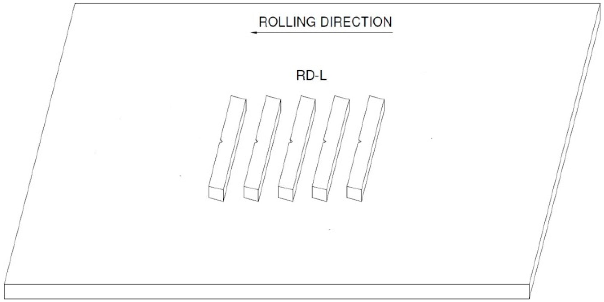
An investigation was carried out on five Charpy samples. These samples were machined according the ISO 148-1:2016 standard. An instrumented RKP 450 Zwick/Roell impact machine with U-type hammer and a 2 mm radius striker in accordance with ISO 148-2:2016 was used. In this research, the velocity at impact was = 5.234 m/s. Samples were tested at a room temperature of 21.5 °C. The material used in this research was pipeline steel API 5L X80. The orientation of the CVN samples is shown in Figure 3.
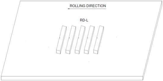
Figure 3.
Orientation of CVN samples.
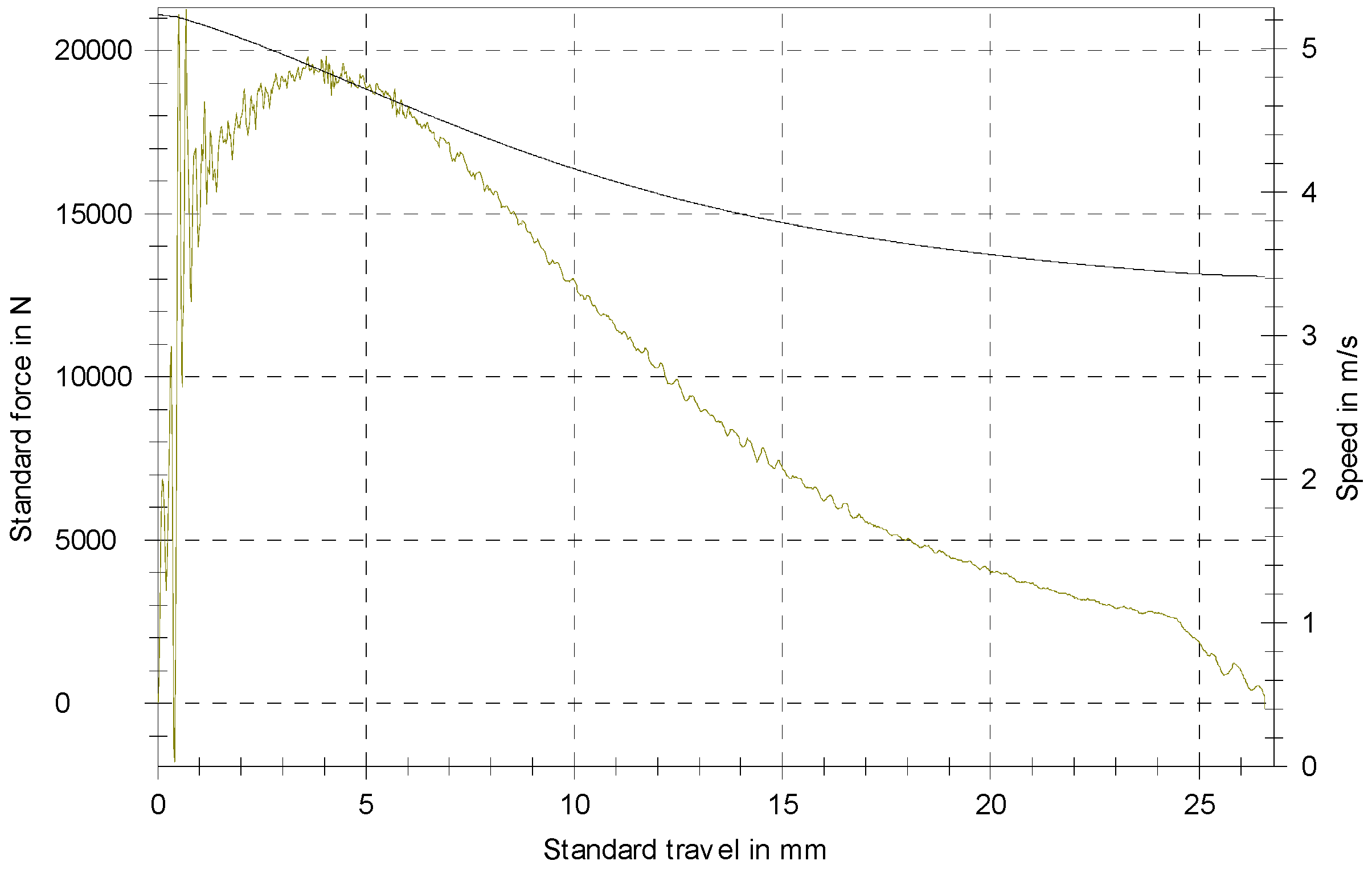
In Figure 4, the genuine force-displacement speed diagram of a single specimen is presented.
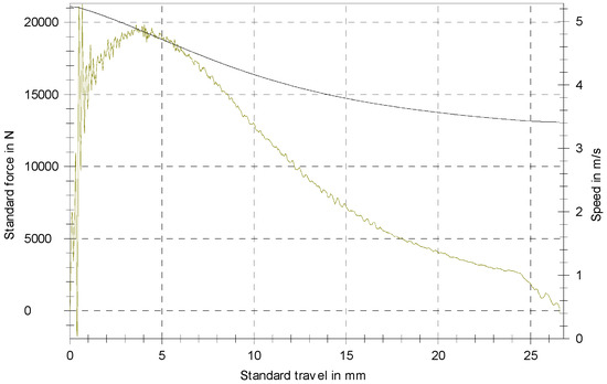
Figure 4.
Force-displacement diagram.
The average values of estimated force measured on the instrumented Charpy machine are given in Table 2. The forces were estimated according to ISO 14556:2015.
Table 2.
Results of force under dynamic conditions at 21.5 °C.
Dynamic strengths were estimated according to Equations (8) and (9). The results of dynamic yield strength and dynamic tensile strength of the specimens tested by the instrumented Charpy method are given in Table 3.
Table 3.
Results of strength under dynamic conditions at 21.5 °C.
Tensile tests were carried out according to ISO 6892-1:2016 on a Messphysik Beta 250 kN machine, class 0.5, equipped with Messphysik Laser extensometer class 1. The samples were tested at an ambient temperature of 21.5 °C. The crosshead speed was 1.1 mm/min. The average results of the mechanical properties of four API 5L X80 samples are given in Table 4.
Table 4.
Mechanical properties obtained from a tensile test at 21.5 °C.
In addition to mechanical tests, the measurement of chemical composition of API 5L X80 was carried out on the Leco Glow Discharge Spectrometer GDS 500 machine. The samples were ground with 500 SiC paper under water. The average values of three measurements are given in Table 5.
Table 5.
Chemical composition, weight %.
5. Discussion
As pointed out earlier, in the available published papers, the value of the constraint factor at maximum force obtained during the instrumented impact test was not known. Therefore, the comparison based on the constraint factor between the tensile test and the instrumented impact test was only done at the yield strength.
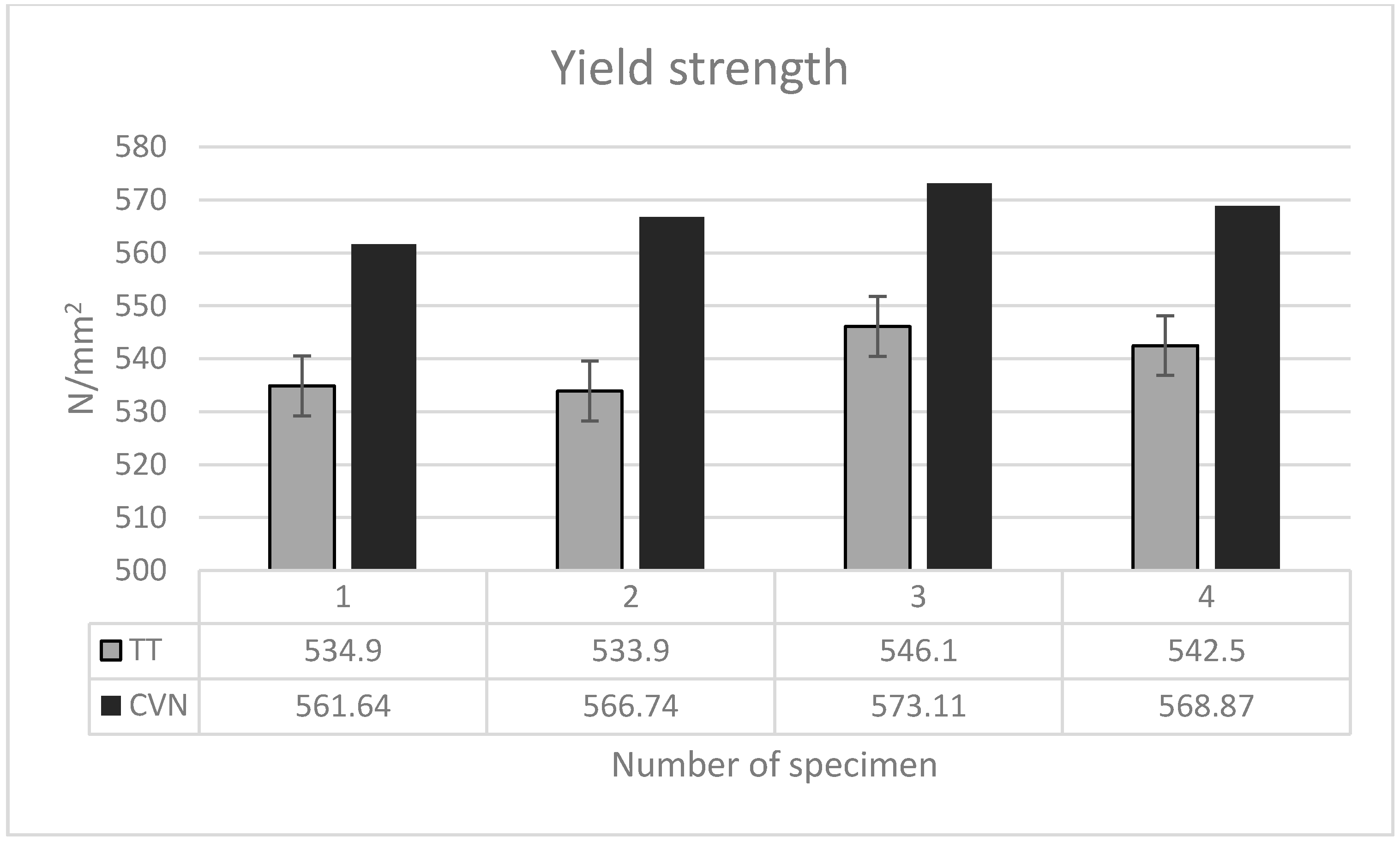
An analysis of the yield strength shows that the values of the dynamic yield strength obtained by the instrumented impact method are about 5% higher than the ones from the tensile test; Figure 5.

Figure 5.
Yield strength comparison.
Fang et al. [15] stated that the higher results are due to the effect of the loading rate increase. In their research, the difference is about 20%.
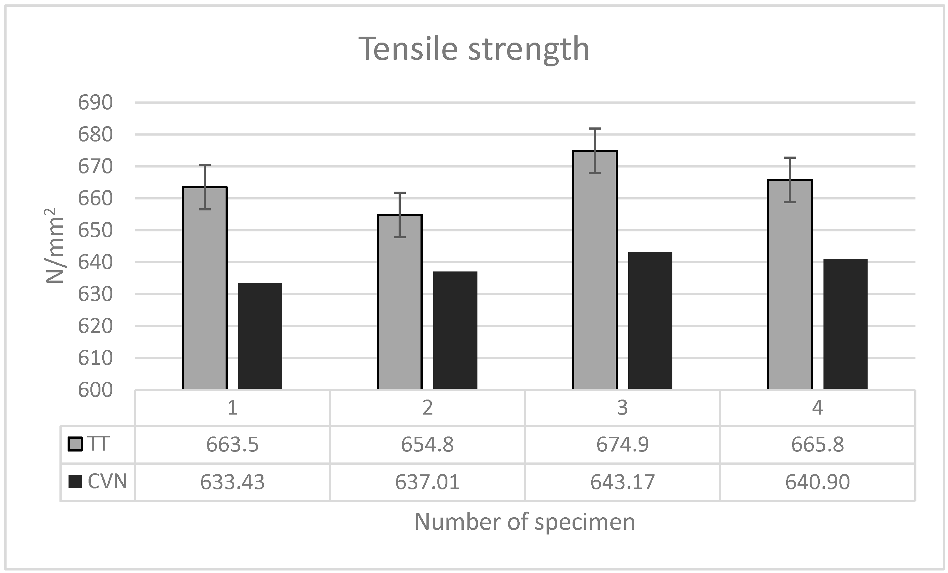
Opposite to the yield strength values, at maximum stress, the dynamic tensile strength values obtained by the instrumented impact testing were about 4% lower than the ones from the tensile test values; Figure 6.

Figure 6.
Tensile strength comparison.
The reason for the higher tensile test values could be that the striker of the impact machine decelerates (315.11 m/s2) during the test (bending the Charpy specimen) from its velocity at impact ( = 5.234 m/s) to the speed at maximum strength of 4.842 m/s. Furthermore, the appearance of the crack at the root tip contributes to the lower loading rate.
6. Conclusions
The results of the yield and tensile strength values obtained in this research indicate a good relation between the tensile and instrumented Charpy impact test. In both measured mechanical properties, the difference is around 4%, i.e., 5%. This research also contains additional results for the constraint factor. From the values of the constraint factor at maximum force, the dynamic tensile strength was estimated. The influence of the width of the striker was included during the evaluation of the constraint factor [11]. In this paper, the authors used Ewing’s six equations to estimate the value of the constraint factor at the maximum force. It was found that the constraint factor value increases as the bending of the Charpy specimen continues. For a better understanding of material behavior, further extensive research is required on the constraint factor and the plastic deformation of the Charpy specimen above the yield point.
Author Contributions
Conceptualization, D.M.; Data curation, Ž.A.; Formal analysis, D.M.; Investigation, D.M.; Methodology, Ž.A.; Project administration, Ž.A.; Resources, Ž.A.; Supervision, Ž.A.; Validation, Ž.A. and D.M.; Visualization, D.M.; Writing—original draft, D.M.; Writing—review & editing, Ž.A.
Funding
This research received no external funding.
Acknowledgments
The authors are very grateful to Donald R. Ireland for his advice on the instrumented method and Davor Kolednjak for supplying the material for testing.
Conflicts of Interest
The authors declare no conflict of interest.
References
- Kobayashi, T. Progress in the Instrumented Charpy Impact Test. J. Soc. Mater. Sci. 2002, 51, 771–779. [Google Scholar] [CrossRef]
- Siewert, P.A.; McCowan, C.; Manahan, M. Pendulum Impact Machines: Procedures and Specimens; ASTM STP 1476; American Society for Testing and Materials: West Conshohocken, PA, USA, 2006; pp. 3–12. ISBN 0-8031-3402-9. [Google Scholar]
- Siewert, T.A.; Manahan, M.P. Pendulum Impact Testing: A Century of Progress; ASTM STP 1380; American Society for Testing and Materials: West Conshohocken, PA, USA, 2000; pp. 198–210. ISBN 0-8031-2864-9. [Google Scholar]
- Lucon, E. Estimating dynamic ultimate tensile strength from instrumented Charpy data. Mater. Des. 2016, 97, 437–443. [Google Scholar] [CrossRef]
- Fang, J.; Wang, C. Experimental Study on the Characteristic Loading of Instrumented Impact; Technical Center, Baoshan Iron and Steel Co., Ltd.: Shangai, China, 2015; 10p, Available online: https://www.researchgate.net/publication/268421318_Experimental_Study_on_the_Characteristic_Loading_of_Instrumented_Impact (accessed on 26 June 2018).
- Fang, J. Strength and toughness properties of steels under dynamic loading. In Fracture of Nano and Engineering Materials and Structures, Proceedings of the 16th European Conference of Fracture, Alexandroupolis, Greece, 3–7 July 2006; Springer: Dordrecht, The Netherlands, 2006; pp. 503–504. [Google Scholar]
- Prandtl, L. Über die härte plastischer körper. Nachr. Ges. Wiss. Gött. Math-Phys. Kl. 1920, 1920, 74–85. (In German) [Google Scholar]
- Green, A.P. The plastic yielding of notched bars due to bending. Q. J. Mech. Appl. Math. 1953, 6, 223–229. [Google Scholar] [CrossRef]
- Green, A.P.; Hundy, B.B. Initial plastic yielding in notch bend tests. J. Mech. Phys. Solids 1956, 4, 128–144. [Google Scholar] [CrossRef]
- Lianis, G.; Ford, H. Plastic yielding of single notched bars due to bending. J. Mech. Phys. Solids 1958, 7, 1–20. [Google Scholar] [CrossRef]
- Alexander, J.M.; Komoly, T.J. On the yielding of a rigid/plastic bar with an Izod notch. J. Mech. Phys. Solids 1962, 10, 265–275. [Google Scholar] [CrossRef]
- Ewing, D.J.F. Calculations on the bending of rigid/plastic notched bars. J. Mech. Phys. Solids 1968, 16, 205–213. [Google Scholar] [CrossRef]
- Hill, R. The Mathematical Theory of Plasticity; Oxford University Press: Oxford, UK, 2004; pp. 213–262. ISBN 0198503679. [Google Scholar]
- Server, W.L. General yielding of Charpy V-notch and precracked Charpy specimens. J. Eng. Mater. Technol. 1978, 100, 183–188. [Google Scholar] [CrossRef]
- Fang, J.; Ding, F.L. Force based analysis on the instrumented Charpy impact and its industrial application. In Proceedings of the DYMAT 2009, Brussels, Belgium, 7–11 September 2009; EDP Sciences: Les Ulis, France, 2009; pp. 779–783. [Google Scholar]
© 2018 by the authors. Licensee MDPI, Basel, Switzerland. This article is an open access article distributed under the terms and conditions of the Creative Commons Attribution (CC BY) license (http://creativecommons.org/licenses/by/4.0/).