Article

Vacuum Brazing Ti–15–3 with a TiNiNb Braze Alloy

1
Department of Materials Science and Engineering, National Taiwan University, Taipei 106, Taiwan
2
Institute of Materials Engineering, National Taiwan Ocean University, Keelung 202, Taiwan
*
Author to whom correspondence should be addressed.
Metals 2019, 9(10), 1085; https://doi.org/10.3390/met9101085
Submission received: 14 September 2019 / Revised: 5 October 2019 / Accepted: 7 October 2019 / Published: 9 October 2019

Abstract

:
Among all types of brazing fillers, Ti-based fillers show satisfactory joint strengths in brazing titanium alloys. However, the major concern in using such fillers is the formation of Cu/Ni/Ti intermetallic compound(s) in the joint. In this study, a Ti–15–3 alloy was vacuum brazed with a clad Ti–35Ni–25Nb foil. The brazed zone consisted of a Ti2Ni intermetallic compound in a (β-Ti,Nb)-rich matrix for specimen brazing at 1000 °C/600 s. Raising brazing temperature and time resulted in the Ti2Ni dissolving into the (β-Ti,Nb)-rich matrix. For the specimen brazing at 1100 °C/600s, Ti2Ni could only be observed at the grain boundaries of the (β-Ti,Nb)-rich matrix. After further raising it to 1200 °C/600 s, the Ti2Ni intermetallic compound was all dissolved into the (β-Ti,Nb)-rich phase. The average shear strength was significantly raised from 140 (1000 °C/600 s) to 620 MPa (1100 °C/3600 s). Crack initiation/propagation in the brittle Ti2Ni compound with the cleavage fractograph were changed into the Ti–15–3 base metal with a ductile dimple fractograph. The advantage of using Nb in the TiNiNb filler foil was its ability to stabilize β-Ti, and most of the Ni in the braze alloy was dissolved into the β-Ti matrix. The brazed joint could be free of any intermetallic phases with a proper brazing cycle applied, and the joint was suitable for a few harsh applications, e.g., repeated stresses and impact loadings.

1. Introduction

The joining of titanium and its alloys is important in the industry, because joining technology is a fundamental process of manufacturing [1,2]. The similar/dissimilar joining of Ti and its alloys has been widely evaluated in the literature for many applications [3,4,5,6,7,8,9]. Simoes proposed a dissimilar joining of titanium alloys as well as many advanced ceramics, and they produced components with extraordinary and unique properties for the automotive and aerospace industries [10]. The joining of a high strength Ti–6Al–4V alloy has been reported for structural demands in aerospace and medical applications [11].
Welding and brazing are two alternative approaches of the metallurgical bonding of Ti alloys [12]. For certain applications such as the manufacturing of heat exchangers and dissimilar joining, brazing is more appropriate than welding [12]. Compared with fusion welding, brazing has the advantage of bonding hundreds of joints at one time, and the distortion of the heat exchanger is minimized. Brazing is different from fusion welding because very limited base metal melting is observed in brazing. The dilution of the base metal in brazing is greatly confined in comparison to fusion welding. Consequently, brazing dissimilar alloys is easier than fusion welding.
For a joint using the proper welding procedure, the strength of the weldment can be higher than that of the base metal. In contrast, the strength of the brazed joint is usually less than that of the base metal. It is preferred that the brazed joint exhibits a bonding strength and corrosion resistance close to the base metal [1,2]. For instance, Ti–6Al–4V has been successfully brazed with a 718 nickel-based alloy and 316L stainless steel using Au-based and Ti–Cu based fillers, respectively [7,8]. The brazed joints presented good joint strengths for application.
Ti-based filler metals demonstrate high joint strengths close to their base metal in brazing titanium alloys among all types of brazing fillers [13,14,15,16]. In previous studies, clad Ti–(Zr)–Cu–Ni foils were successfully applied in the similar/dissimilar brazing of many Ti alloys, and the brazed joints showed good bonding strengths [17,18,19,20]. However, one of the major concerns in using such filler alloys is the formation of Cu/Ni/Ti intermetallic compounds in the joint. Since Ni and Cu are important MPDs (melting point depressants) in these braze alloys, they simultaneously react with Ti in brazing [2]. The elimination of such brittle phase(s), if possible, becomes a crucial issue in application of such Ti-based filler metals [2,19,20].
The clad Ti–Ni–Nb braze filler provides an alternative in the brazing of Ti alloys [20]. Because Nb is a β stabilizer in Ti alloys, the microstructure of the brazed joint could be dominated by β-Ti. It is possible that the Ti–Ni intermetallic compound could be alloyed in a β-Ti matrix with aid of a higher brazing temperature/time period [20]. A Ti/Ti35Ni25Nb/Ti joint with a minimum amount of Ti–Ni intermetallic compounds was acquired in previous study [18]. Ti–15–3 belongs to the category of metastable beta titanium, and it is widely applied in the industry. It has low material and strip processing costs [21,22,23]. The purpose of this investigation was to braze a Ti–15–3 beta titanium alloy using a beta titanium filler metal, Ti–35Ni–25Nb, in order to remove all potential detrimental phase(s) of the joint. If the brazed joint was free of brittle intermetallic compounds, a reliable bond could be obtained for industrial application.

2. Materials and Methods

The chemical composition of Ti–15–3 plates (wt%) is 3Al, 3Cr, 3Sn, 15V, and the Ti balance, as shown in Table 1. The Ti–15–3 plate was wire cut into a size of 3 mm in thickness, 10 mm in length and 7 mm in width. All Ti–15–3 specimens were ground by SiC papers up to 800 grit with a scratch depth below 22 μm [24,25]. They were subsequently degreased in an ultrasonic bath with ethanol as a solution for 600 s before brazing. The clad Ti–35Ni–25Nb (wt%) foil with a 50 μm thickness was the brazing filler metal. Table 1 displays the nominal compositions of the materials used in the experiment. A traditional vacuum furnace with a vacuum of 10−5 mbar equipped with a quartz tube was used in the brazing experiment. The heating rate was kept at 0.33 °C/s, and all brazed specimens were preheated at 900 °C for 600 s. Because the clad Ti–35Ni–25Nb foil does not melt below 950 °C, 1000 °C was chosen as the initial brazing temperature. Higher brazing temperatures, 1100 and 1200 °C, were also applied to investigate the microstructural evolution of the brazed joints with different brazing conditions. In the experiment, the Ti–15–3 alloy was vacuum brazed at 1000, 1100, 1200 °C for 600 and 3600 s.
The joint cross section was inspected by the JEOL JXA 8200 EPMA (electron probe microanalyzer) (JEOL Ltd., Tokyo, Japan) with a WDS (wavelength dispersive spectroscope) to quantitatively analyze the compositions at different positions. Microstructure and crystallographic analyses of selected joints were performed by an FEI Quanta 650 FESEM (field emission scanning electron microscope) with an Oxford Nordlys Max 3 EBSD (electron backscatter diffraction) device (FESEM, FEI Corp., Hillsboro, OR, USA). After vacuum brazing, a double lap joint, Ti–15–3/Ti–35Ni–25Nb/Ti–15–3, was subjected to a shear test using a screw-driven tensile test facility with a compressive rate of 0.02 mm/s [8,13].Ti–15–3 joints brazing at 1000, 1100, 1200 °C for 600 and 3600 s were evaluated in the shear test. For each brazing condition, three specimens were tested, and the standard deviation was included in the experimental result. Fractographs of selected joints after the shear test were obtained from EPMA observations.

3. Results and Discussion

Figure 1 presents the EPMA BEIs (backscattered electron images) of the Ti–15–3/Ti–35Ni–25Nb/Ti–15–3 joint brazing at 1000 °C for 600 s. In Figure 1 and Table 2, the brazed zone is shown to contain at least two phases; these were deduced to be Ti2Ni (marked A) and a (β-Ti,Nb)-rich solid solution alloyed with Ni, V, Al, Cr, and Sn (marked B). The composition of Location C was approximately T2Ni, and the composition of Location E was close to the Ti–15–3 base metal. According to the Nb–Ti binary alloy phase diagram, β-Ti could be stabilized by alloying with Nb, and it yielded a (β-Ti, Nb)-rich solid solution [26]. Based on the Ni–Ti phase diagram, Ti reacted with Ni to form a Ti2Ni intermetallic compound [26]. The experimental observations are consistent with the phase diagrams.
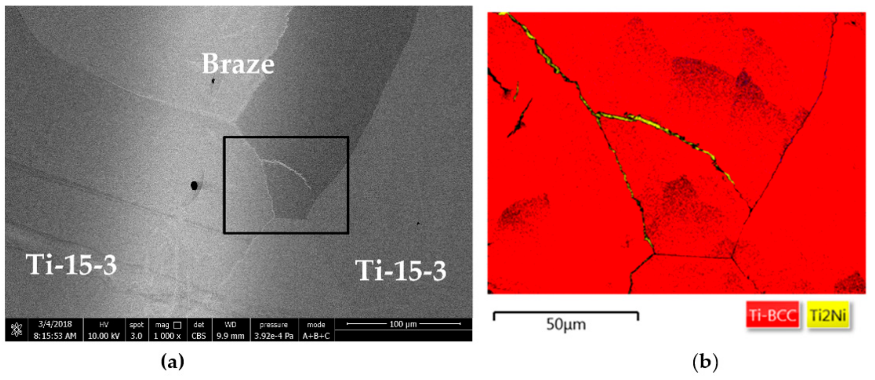
Figure 2 shows FESEM/EBSD analyses of the brazed zone at 1000 °C for 3600 s. After increasing the brazing time, the brazed zone Ti2Ni was found to precipitate along the grain boundaries of the (β-Ti,Nb)-rich matrix, as demonstrated by Figure 2b. The Ti reacted with Ni to form grain boundary Ti2Ni, and most of the Ti2Ni intermetallic compound dissolved into the (β-Ti,Nb)-rich matrix. This agrees with the Ti–Ni phase diagram [26]. It is worth mentioning that the presence of a continuous Ti2Ni intermetallic phase along the grain boundaries of the (β-Ti,Nb)-rich matrix could be detrimental to reliability of the joint. Cracks could be initiated and propagated along the intergranular brittle phase if stress is applied.
Figure 3 shows the EPMA BEIs of the Ti–15–3/Ti–35Ni–25Nb/Ti–15–3 joint brazing at 1100 °C/600 s. Table 3 displays EPMA quantitative chemical analyses of the images in Figure 3. According to Figure 3 and Table 3, raising the temperature caused the dissolution of the Ti2Ni intermetallic compound into the (β-Ti,Nb)-rich matrix (marked G). The solubility of Ni in β-Ti was approximately 10 at% at 942 °C [26]. It is worth mentioning that high V and Nb contents strongly stabilized β-Ti. Therefore, β-Ti was stable at room temperature, and 3.9 at% Ni was dissolved in the (β-Ti,Nb)-rich matrix, as marked by G in Figure 3. Similar to the aforementioned result, Ti2Ni mostly observed along the grain boundaries of the (β-Ti,Nb)-rich grains (marked F in Figure 3).
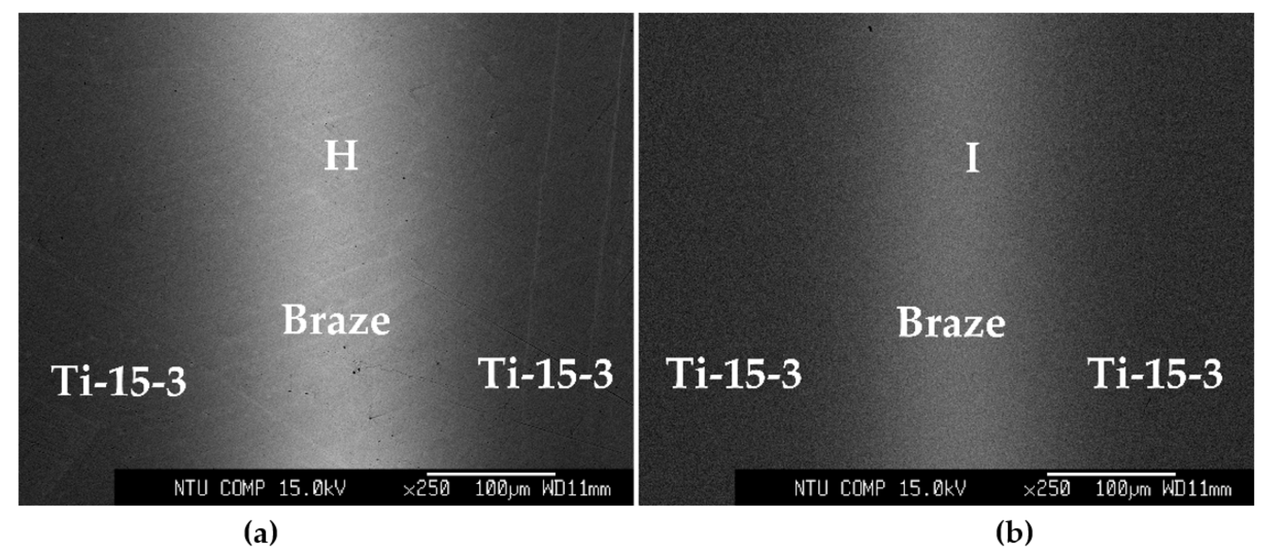
The amount of the grain boundary Ti2Ni compound could be further decreased with increased brazing temperatures/times. Figure 4 shows the EPMA BEIs of the vacuum-brazing specimens at 1100 and 1200 °C/600 s. Raising the brazing time/temperature greatly enhanced the dissolution of Ti2Ni into the (β-Ti,Nb) matrix, as demonstrated by Positions H and I in Figure 4 and Table 4. The Ti2Ni intermetallic compound can almost not be observed in Figure 4. Meanwhile, the (β-Ti,Nb)-rich matrix was alloyed with Ni, V, Al, Cr, and Sn. Figure 5 shows FESEM/EBSD analyses of the brazed zone brazing at 1200 °C/600 s. According to Figure 5a, the brazed zone contained no Ti2Ni. This was confirmed by the EBSD phase fraction identification map, as demonstrated in Figure 5b. Figure 5c displays the inverse pole figure of Figure 5b, and the average grain size of the (β-Ti,Nb)-rich matrix exceeded 250 μm. A high brazing temperature caused the coarsening of the (β-Ti,Nb)-rich matrix.
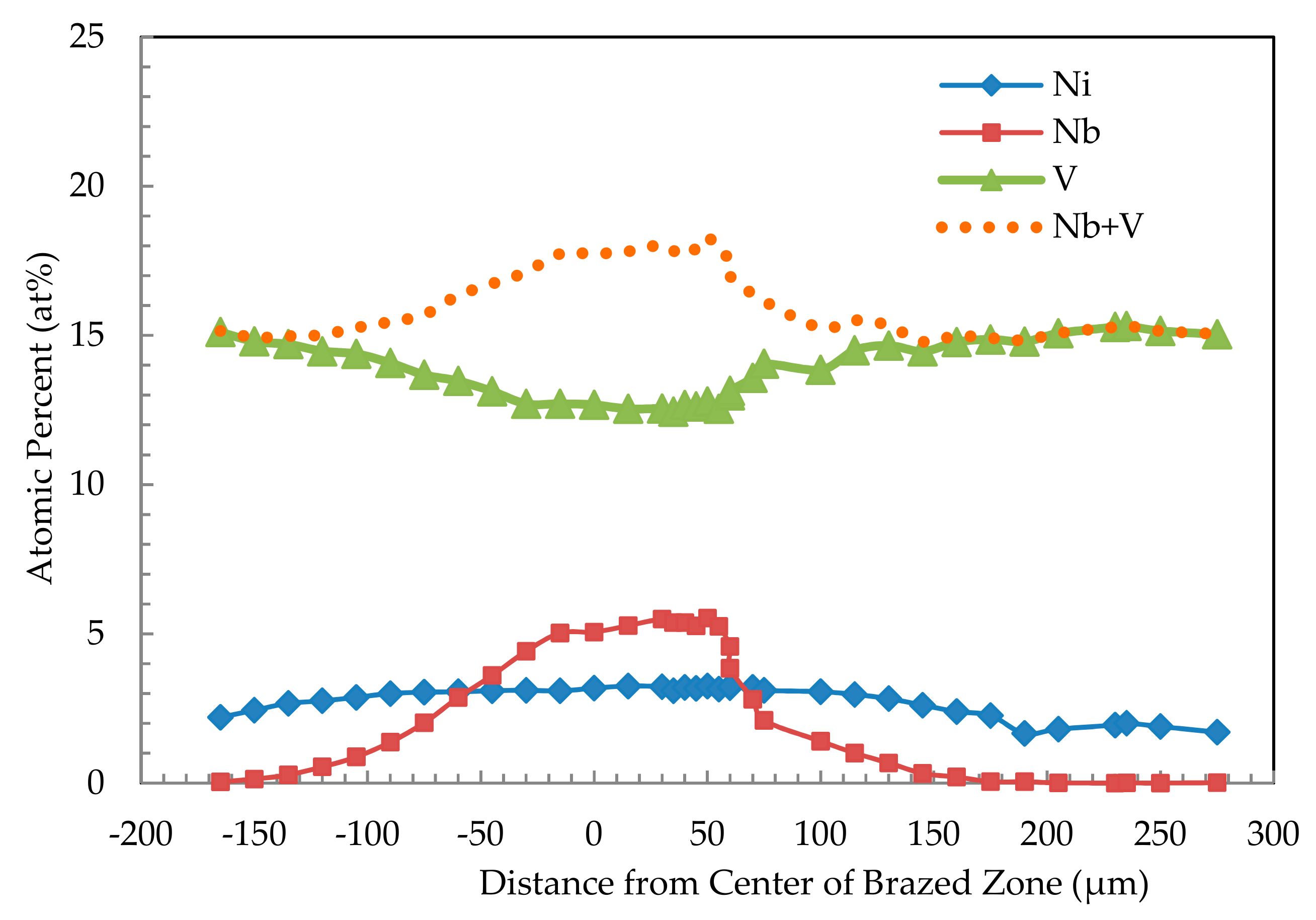
Figure 6 displays EPMA quantitative chemical analyses of the Ni, Nb and V profiles across the joint brazing at 1200 °C for 3600 s. The central brazed zone was rich in Nb and V, and both the Nb–Ti and Ti–V phase diagrams belong to the category of β isomorphous systems [26,27]. The Nb was diffused into the Ti–15–3 base metal driven by the concentration gradient. Meanwhile, the dissolution of the Ti–15–3 base metal in the brazed zone resulted in an increased V content of the joint. According to Figure 6, the Ni was dissolved in the (β-Ti,Nb)-rich matrix with a maximum content below 4 at%, as illustrated in Figure 6. The amount of Nb and V in the central brazed zone was above 15 at%, so β-Ti alloyed with Ni could be stabilized to room temperature without decomposing into Ti2Ni and α-Ti.
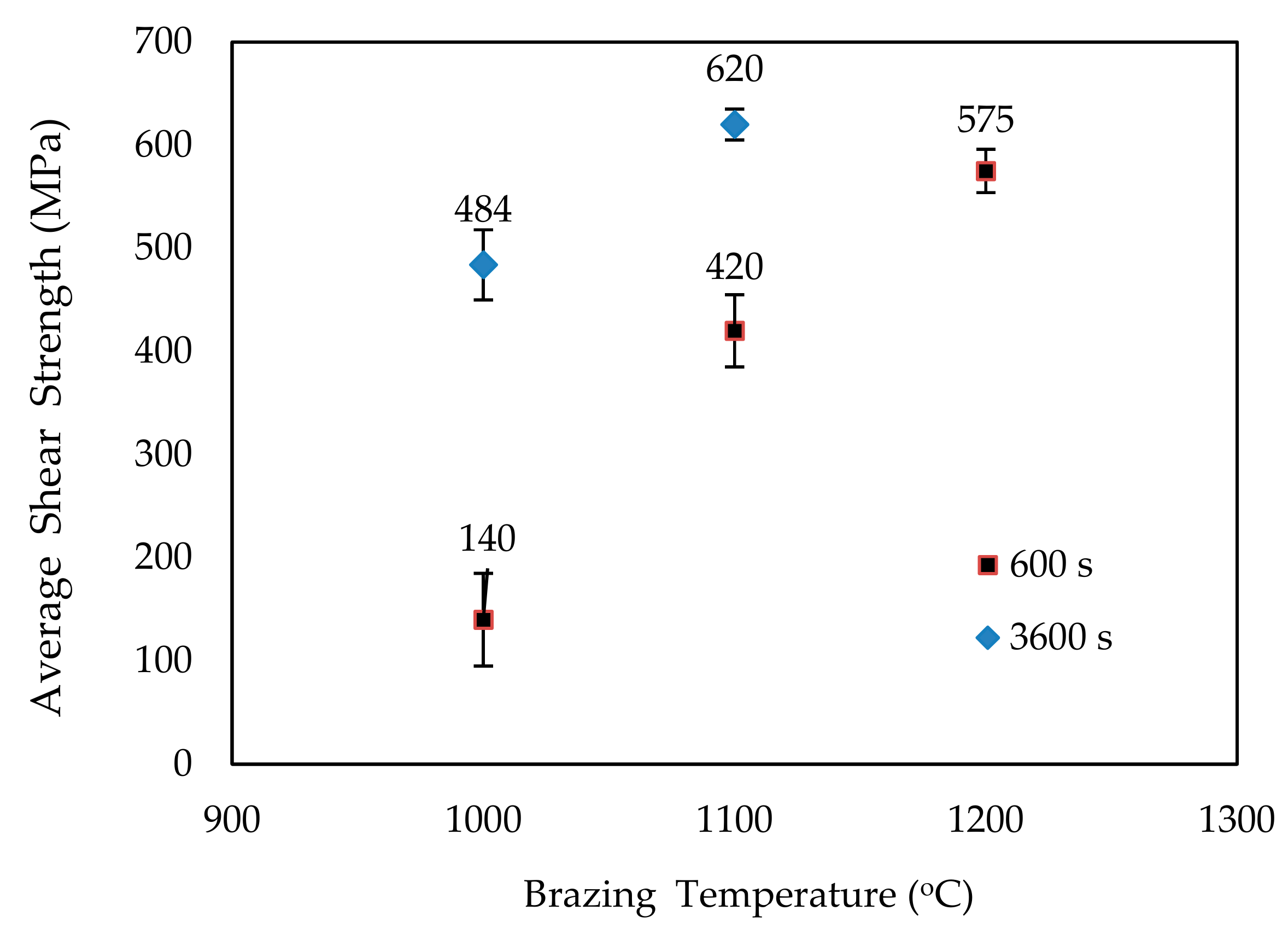
Figure 7 shows average shear strengths of the Ti–15–3/Ti–35Ni–25Nb/Ti–15–3 joints with various brazing thermal cycles. For the specimen brazing at 1000 °C/600 s, the lowest shear value of 140 MPa was observed. Shear strengths were greatly increased with the raising brazing temperature, and the highest shear value of 620 MPa was achieved for the joint brazing at 1100 °C/3600 s. Additionally, the standard deviation of the shear strength was decreased as the temperature increased. This implies that fracture of the joint was ductile, and the value was more reliable for the specimen brazing at a higher temperature and a longer time period.
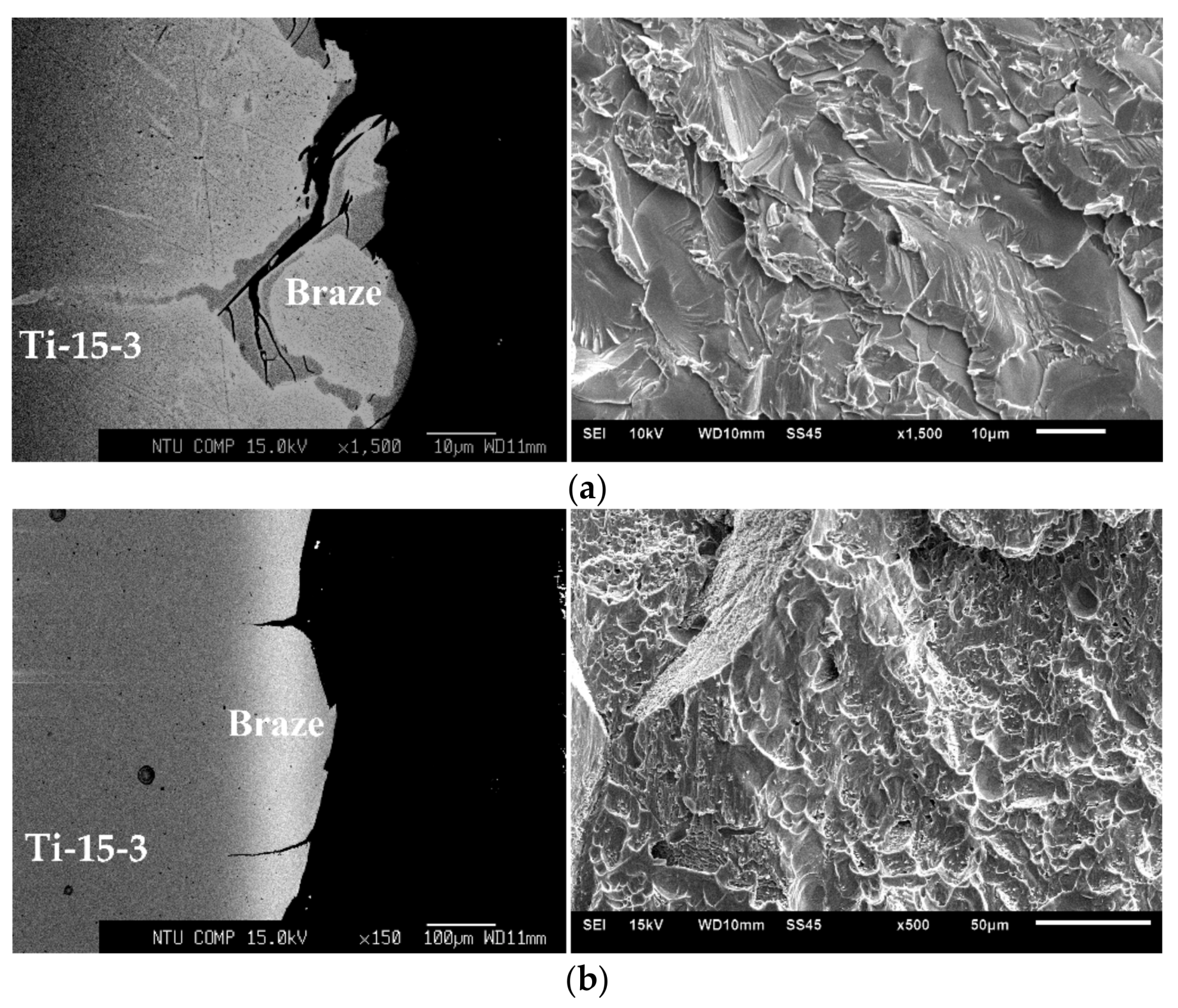
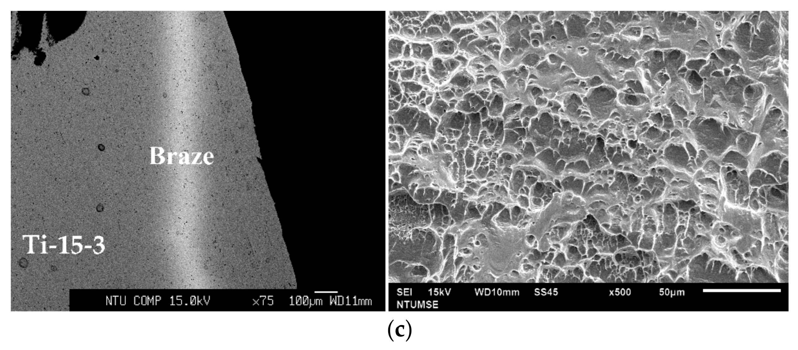
Figure 8 displays EPMA BEI cross-sectional views as well as SEI-fractured surfaces after shear tests. Brittle cleavage was widely observed for the joint brazing at 1000 °C/600 s (Figure 8a), and the standard deviation of the shear strength was as high as 45 MPa (Figure 7). Cracks initiated and propagated along the central Ti2Ni compound in the joint, as demonstrated in Figure 8a. A high standard deviation in the shear strength value indicated the inherent brittleness of the Ti2Ni intermetallic compound. Raising the brazing temperature/time greatly lowered the amount of Ti2Ni in the joint, so its bonding strength was greatly increased. The quasi-cleavage fracture of the joint brazed at 1100 °C/600 s is shown in Figure 8b. According to Figure 3, Ti2Ni was located along the grain boundary of the (β-Ti,Nb)-rich grains. Both the intergranular and transgranular fractured surfaces can be observed in Figure 8b. In contrast, the Ti2Ni intermetallic compound was absent from the joint with the brazing at 1200 °C/600 s, and the joint was fractured in the Ti–15–3 base metal after the shear test. The ductile dimple fracture covered almost the entire fractured surface, as displayed in Figure 8c.
Compared with traditional clad Ti–Ni–Cu filler metals, the application of a TiNiNb filler to braze Ti alloys has a strong potential for industrial use. Nb is a β isomorphous type stabilizer in Ti alloys. The stabilized β-Ti was able to dissolve the Ti2Ni intermetallic compound in the brazed zone when the appropriate thermal cycle is applied. In contrast, Ni and Cu are β eutectoid type stabilizers in Ti alloys, and β-Ti was not stable at low temperatures. Ti2Ni/Ti2Cu intermetallic phases could be formed in the brazed zone upon the cooling cycle of the brazing via the eutectoid decomposition of β-Ti → Ti2Cu/Ti2Ni + α-Ti. This study clarifies the effect of the strong β-stabilizer, Nb, in the Ti-based filler metal. The alloying of the Nb ingredient into the Ti-based filler metal is beneficial for stabilizing β-Ti in brazing, and most of the Ti2Ni intermetallic compounds can be easily dissolved into the β-Ti matrix. Therefore, a brazed joint that is free of any intermetallic phases and that has a joint strength comparable to the base metal can be achieved.
According to the experimental results, the formation of a Ti Ni intermetallic phase in the brazed zone could be completely removed via an appropriate brazing cycle. Most of the Ni in the TiNiNb filler could be dissolved into the (β-Ti,Nb)-rich matrix, so a reliable joint, free of any brittle intermetallic phases can be acquired. When the brazing temperature of the TiNiNb filler exceeded 1000 °C, the coarsening of the titanium substrate was observed in the experiment. Lowering the brazing temperature of the TiNiNb filler below 1000 °C should be the next research target in the future.

4. Conclusions

The Ti–15–3 alloy was vacuum-brazed using a clad Ti–35Ni–25Nb braze. The brazed zone consisted of a Ti2Ni intermetallic compound in the (β-Ti,Nb)-rich matrix for the specimen brazing at 1000 °C/600 s. Raising the brazing time/temperature resulted in the dissolution of the Ti2Ni intermetallic compound into the (β-Ti,Nb)-rich matrix. For the specimen brazing at 1100 °C/600 s, Ti2Ni could only observed along the grain boundaries of the (β-Ti,Nb)-rich matrix. After further raising the temperature to 1200 °C for 600 s, the Ti2Ni was completely dissolved into the (β-Ti,Nb)-rich phase. The absence of the brittle Ti2Ni intermetallic phase in the joint was beneficial for joint reliability. The average shear strength was greatly increased from 140 MPa (1000 °C/600 s) to 620 MPa (1100 °C/3600 s). Crack initiation and growth along the brittle Ti2Ni compound with the cleavage fractograph was changed into the Ti–15–3 base metal with the ductile dimple fractograph. The clad Ti–35Ni–25Nb braze is an appropriate filler alloy to braze the β-Ti alloy if a proper thermal cycle is applied. The advantage of Nb in the TiNiNb filler foil is its ability to stabilize β-Ti, and most of the Ni content in the braze alloy can be dissolved into the β-Ti matrix. The brazed joint could be free of any intermetallic phases. A brazed joint with no brittle intermetallic phase is suitable for a few harsh cases, e.g., repeated stresses and impact loadings.

Author Contributions

Conceptualization, L.-W.T. and R.-K.S.; data curation, C.-S.K. and S.-B.W.; formal analysis, C.-S.K. and S.-B.W; funding acquisition, R.-K.S.; methodology, R.-K.S.; project administration, R.-K.S.; supervision, R.-K.S.; validation, L.-W.T.; writing—original draft, R.-K.S.; and writing—review & editing, C.-S.K. and L.-W.T.

Funding

This research was funded by the Ministry of Science and Technology, Taiwan (grant number: MOST 106-2221-E-002-174-MY3).

Acknowledgments

Appreciation to Hsin-Chih Lin and Chung-Yuan Kao for EPMA operation in Instrumentation Center, National Taiwan University.

Conflicts of Interest

The authors declare no conflict of interest.

References

  1. Olson, D.L. Metals Handbook: Volume 6, Welding Brazing and Soldering; ASM International: Materials Park, OH, USA, 1990. [Google Scholar]
  2. Humpston, G.; Jacobson, D.M. Principles of Soldering and Brazing; ASM International: Materials Park, OH, USA, 1993. [Google Scholar]
  3. Yao, Q.; Cheng, H.C.; Fan, J.L.; Yan, H.X.; Zhang, C.G. High strength Mo/Ti6Al4V diffusion bonding joints: Interfacial microstructure and mechanical properties. Inter. J. Refrac. Met. Hard Mater. 2019, 82, 159–166. [Google Scholar] [CrossRef]
  4. Oliveira, J.P.; Panton, B.; Zeng, Z.; Andrei, C.M.; Zhou, Y.; Miranda, R.M.; Fernandes, F.M.B. Laser joining of NiTi to Ti6Al4V using a Niobium interlayer. Acta Mater. 2016, 105, 9–15. [Google Scholar] [CrossRef]
  5. Velmurugan, C.; Senthilkumar, V.; Sarala, S.; Arivarasan, J. Low temperature diffusion bonding of Ti-6Al-4V and duplex stainless steel. J. Mater. Proc. Tech. 2016, 234, 273–279. [Google Scholar] [CrossRef]
  6. Zhou, X.F.; Duan, J.A.; Zhang, F.; Zhong, S.S. The study on mechanical strength of titanium-aluminum dissimilar butt joints by laser welding-brazing process. Materials 2019, 12, 712. [Google Scholar] [CrossRef] [PubMed]
  7. Ogura, T.; Miyoshi, K.; Matsumura, T.; Imai, T.; Saida, K. Improvement of joint strength in dissimilar friction welding of Ti-6Al-4V alloy to type-718 nickel-based alloy using the Au-Ni interlayer. Sci. Tech. Weld. Join. 2019, 24, 327–333. [Google Scholar] [CrossRef]
  8. Xia, Y.Q.; Dong, H.G.; Hao, X.H.; Li, P.; Li, S. Vacuum brazing of Ti6Al4V alloy to 316L stainless steel using a Ti-Cu-based amorphous filler metal. J. Mater. Process. Tech. 2019, 269, 35–44. [Google Scholar] [CrossRef]
  9. Yeh, T.Y.; Shiue, R.K.; Chang, C.S. Microstructural observation of brazed Ti-15-3 alloy using the clad Ti-20Zr-20Cu-20Ni foil. ISIJ Inter. 2013, 53, 726–728. [Google Scholar] [CrossRef]
  10. Simoes, S. Recent progress in the joining of titanium alloys to ceramics. Metals 2018, 8, 876. [Google Scholar] [CrossRef]
  11. Ganjeh, E.; Sarkhosh, H.; Bajgholi, M.E.; Khorsand, H.; Ghaffari, M. Increasing Ti–6Al–4V brazed joint strength equal to the base metal by Ti and Zr amorphous filler alloys. Mater. Charac. 2012, 71, 31–40. [Google Scholar] [CrossRef]
  12. Chen, W.S.; Wang, C.Y.; Shiue, R.K. Brazing Inconel 625 using the copper foil. Metall. Mater. Trans. A 2013, 44A, 5724–5731. [Google Scholar] [CrossRef]
  13. Chang, C.T.; Wu, Z.Y.; Shiue, R.K.; Chang, C.S. Infrared brazing Ti-6Al-4V and SP-700 alloys using the Ti-20Zr-20Cu-20Ni braze alloy. Mater. Lett. 2007, 61, 842–845. [Google Scholar] [CrossRef]
  14. Guedes, A.; Pinto, A.M.P.; Vieira, M.F.; Viana, F. Joining Ti-47Al-2Cr-2Nb with a Ti/(Cu,Ni)/Ti clad-laminated braze alloy. J. Mater. Sci. 2003, 38, 2409–2414. [Google Scholar] [CrossRef] [Green Version]
  15. Zou, Z.H.; Zeng, F.H.; Wu, H.B.; Liu, J.; Li, Y.; Gu, Y.; Yuan, T.C.; Zhang, F.Q. The joint strength and fracture mechanisms of TC4/TC4 and TA0/TA0 brazed with Ti-25Cu-15Ni braze alloy. J. Mater. Eng. Perf. 2017, 26, 2079–2085. [Google Scholar] [CrossRef]
  16. Ren, H.S.; Xiong, H.P.; Chen, B.; Pang, S.J.; Chen, B.Q.; Ye, L. Microstructures and mechanical properties of vacuum brazed Ti3Al/TiAl joints using two Ti-based filler metals. J. Mater. Sci. Tech. 2016, 32, 372–380. [Google Scholar] [CrossRef]
  17. Chang, C.T.; Du, Y.C.; Shiue, R.K.; Chang, C.S. Infrared brazing of high-strength titanium alloys by Ti-15Cu-15Ni and Ti-15Cu-25Ni filler foils. Mater. Sci. Eng. 2006, A420, 155–164. [Google Scholar] [CrossRef]
  18. Pang, S.; Sun, L.; Xiong, H.; Chen, C.; Liu, Y.; Li, H.; Zhang, T. A multi component TiZr-based amorphous brazing filler metal for high-strength joining of titanium alloy. Scripta Mater. 2016, 117, 55–59. [Google Scholar] [CrossRef]
  19. Wang, Y.; Cai, X.Q.; Yang, Z.W.; Wang, D.P.; Liu, X.G.; Liu, Y.C. Effects of Nb content in Ti–Ni–Nb brazing alloys on the microstructure and mechanical properties of Ti–22Al–25Nb alloy brazed joints. J. Mater. Sci. Tech. 2017, 33, 682–689. [Google Scholar] [CrossRef]
  20. Wang, S.B.; Kao, C.S.; Tsay, L.W.; Shiue, R.K. The application of 40Ti-35Ni-25Nb filler foil in brazing commercially pure titanium. Metals 2018, 8, 154. [Google Scholar] [CrossRef]
  21. Walter, J.L.; Jackson, M.R.; Sims, C.T. Titanium and its Alloys: Principles of Alloying Titanium; ASM International: Materials Park, OH, USA, 1993. [Google Scholar]
  22. Zhang, W.J.; Liu, H.H.; Ding, H.; Fujii, H. Grain refinement and superplastic flow in friction stir processed Ti-15V-3Cr-3Sn-3Al alloy. J. Alloys Comp. 2019, 803, 901–911. [Google Scholar] [CrossRef]
  23. Zou, C.H.; Zhou, Q.; Wang, L. A step deformation method for superplasticity improvement of coarse-grained Ti-15V-3Cr-3Sn-3Al. Chin. J. Aeronaut. 2018, 31, 1619–1624. [Google Scholar] [CrossRef]
  24. Lin, C.; Shiue, R.K.; Wu, S.K.; Yang, T.E. Infrared brazed joints of Ti50Ni50 shape memory alloy and Ti-15-3 alloy using two Ag-based fillers. Materials 2019, 12, 1603. [Google Scholar] [CrossRef] [PubMed]
  25. Sandpaper. Wikipedia. Available online: https://en.wikipedia.org/wiki/Sandpaper (accessed on 4 October 2019).
  26. Massalski, T.B. Binary Alloy Phase Diagrams; ASM international: Materials Park, OH, USA, 1990. [Google Scholar]
  27. Smith, W.F. Structure and Properties of Engineering Alloys; McGraw-Hill Inc.: New York, NY, USA, 1993. [Google Scholar]
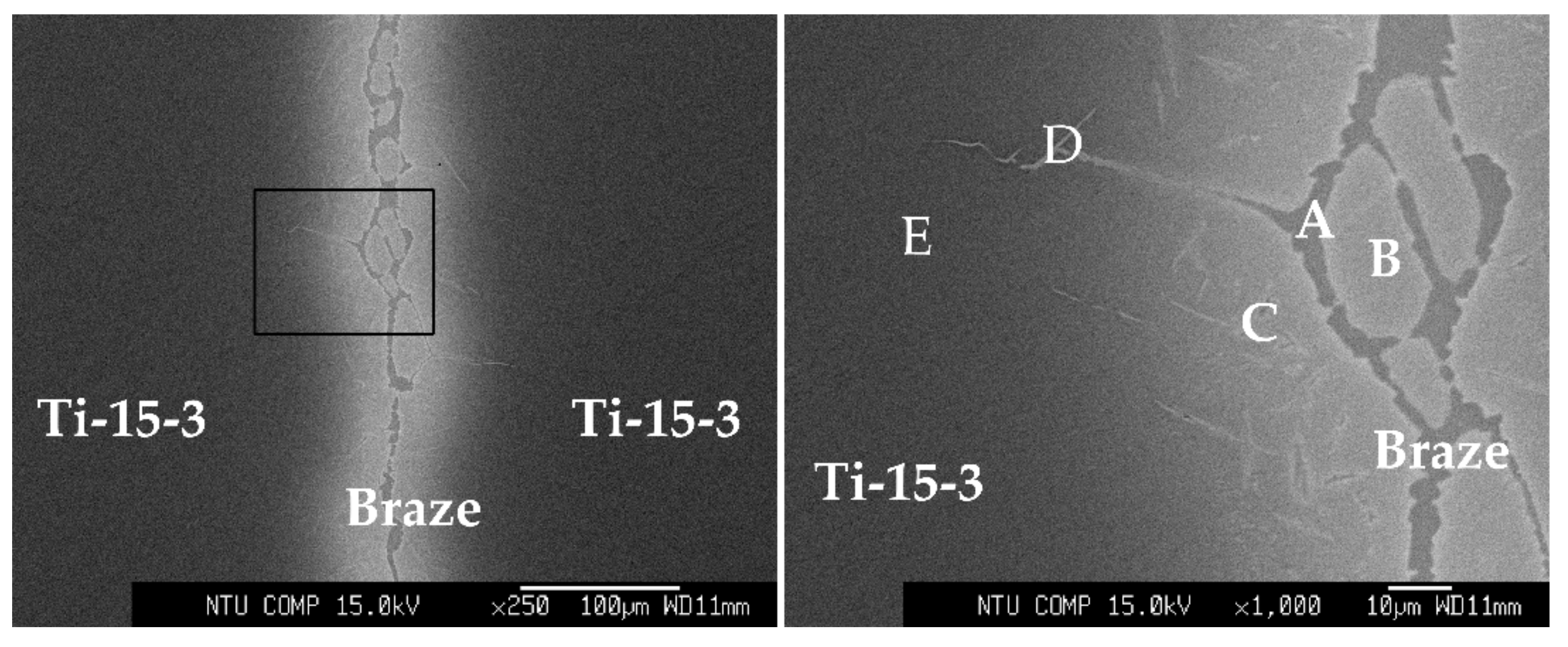
Figure 1. Backscattered electron images (BEIs) of joint vacuum brazing at 1000 °C/600 s.
Metals 09 01085 g001
Figure 2. Field emission scanning electron microscope/electron backscatter diffraction (FESEM/EBSD) analyses of the brazed zone at 1000 °C for 3600 s: (a) BEI and (b) phase fraction of the EBSD analysis in (a).
Metals 09 01085 g002
Figure 3. BEIs of joint vacuum brazing at 1100 °C/600 s.
Metals 09 01085 g003
Figure 4. BEIs of joint vacuum brazing at (a) 1100 °C/3600 s and (b) 1200 °C/600 s.
Metals 09 01085 g004
Figure 5. FESEM/EBSD analyses of the brazed zone brazing at 1200 °C/600 s: (a) BEI, (b) phase fraction of EBSD analysis of (a), and (c) inverse pole figure of (b).
Metals 09 01085 g005
Figure 6. EPMA quantitative chemical analyses across the joint brazing at 1200 °C for 3600 s.
Metals 09 01085 g006
Figure 7. Shear strengths of the Ti–15–3/Ti–35Ni–25Nb/Ti–15–3 joints.
Metals 09 01085 g007
Figure 8. Joint cross-sectional views and fractured surfaces after shear test brazing at (a) 1000, (b) 1100, and (c) 1200 °C/600 s.
Metals 09 01085 g008aMetals 09 01085 g008b
Table 1. Nominal compositions of the materials used in the experiment.
Material/wt%TiNiNbVAlCrSn
Ti–15–376--15333
Ti–35Ni–25Nb403525----
Table 2. Quantitative chemical analyses of the images Figure 1.
Position/at%TiNiNbVAlCrSnPhase
A60.334.11.81.81.20.60.1Ti2Ni
B64.55.515.48.92.51.61.4(β-Ti,Nb)-rich
C61.424.03.86.11.91.51.2close to Ti2Ni
D61.432.10.73.01.11.20.4Ti2Ni
E67.34.46.211.66.02.12.3close to Ti–15–3
Table 3. Quantitative chemical analyses of the images in Figure 3.
Position/at%TiNiNbVAlCrSnPhase
F67.813.94.77.34.11.60.5close to Ti2Ni
G72.43.93.711.35.52.11.0(β-Ti,Nb)-rich
Table 4. Quantitative chemical analyses of the images in Figure 4.
Position/at%TiNiNbVAlCrSnPhase
H71.42.45.612.54.52.61.0(β-Ti,Nb)-rich
I71.23.26.010.94.72.91.0(β-Ti,Nb)-rich