Article

Investigation of Drilling Machinability of Compacted Graphite Iron under Dry and Minimum Quantity Lubrication (MQL)

1
State Key Laboratory for Manufacturing System Engineering, Xi’an Jiaotong University, Xi’an 710054, China
2
Key Lab. of NC Machine Tools and Integrated Manufacturing Equipment of the Education Ministry & Key Lab of Manufacturing Equipment of Shaanxi Province, Xi’an University of Technology, Xi’an 710048, China
*
Author to whom correspondence should be addressed.
Metals 2019, 9(10), 1095; https://doi.org/10.3390/met9101095
Submission received: 4 September 2019 / Revised: 5 October 2019 / Accepted: 8 October 2019 / Published: 11 October 2019
(This article belongs to the Special Issue Cast Irons: Properties and Applications)

Abstract

:
Compacted graphite iron (CGI), which is used as a potential material in the auto industry, is a hard-to-machine material for the different minor elements and for the geometry of graphite with grey cast iron. The machinability of CGI in the drilling process was investigated with a 4-mm diameter fine-grain carbide twist drill under four lubrication conditions, dry (no compressed air), dry (with compressed air), MQL 5 mL/h, and MQL 20 mL/h in this paper. The maximum flank wear, types of wear, and cutting loads were studied for identifying the wear mechanism in drilling of CGI. The tool life in the four experiments of CGI drilling is 639 holes, 2969 holes, 2948 holes, and 2685 holes, respectively. The results showed that the main wear mechanism in drilling of CGI is adhesion and abrasion. Carbon, which originates from the graphite of CGI, can improve the lubrication in the drilling process by comparing with MnS in drilling grey cast iron. The thrust force and torque are more than 1000 N and 150 N*cm after 2700 holes in CGI drilling. Drilling of CGI under dry conditions (with compressed air) and MQL 5 mL/h is feasible.

1. Introduction

Compacted graphite iron (CGI) has been widely utilized for auto parts such as engine block and head because the higher mechanical and thermal loads in the engine are required for abating pollution [1]. The engine manufactured by CGI can provide higher power, lighter weight, thinner wall thickness, and the same elastic buffer compared with the grey cast iron (GI) engine. In contrast with the aluminum engine, the CGI engine have advantages on price, duration, vibration, noise, and energy consumption. Since CGI has higher tensile strength and lower thermal conductivity than GI, the cutting loads are relatively higher while machining CGI [2]. When machining GI, the MnS layer can reduce the oxidation and diffusion during the machining processing, but gives rise to chemical wear, as well as lower tool life. By contrast, in the CGI machining process, it is very difficult to form the MnS layer because the residual sulfur in CGI has combined with magnesium in vermiculizer during the casting process [3]. Therefore, it is very important to ensure the tool life while machining CGI.
Machining of CGI has been studied in all traditional machining methods, such as turning, milling, and drilling [4,5,6,7,8,9]. Rose et al. [8] studied the effect of the content of Ti on tool wear and surface roughness in CGI turning. The results indicated that the increasing content of Ti in CGI could dramatically decrease the tool life. According to Dawson’s research, the tool life in CGI turning could be reduced by 50% while the content of Ti in the CGI increased from 0.01% to 0.02% [5]. Nayyar et al. [6] investigated the effect of tool geometry on cutting load and tool life in turning CGI and found out that a smaller radius of cutting edge could induce lower cutting force and higher tool life. Abele et al. [7] utilized liquid CO2 as lubricant in CGI turning and successfully double the productivity. Da Silva et al. [9] investigated the tool wear effect of cemented carbide coating tools in CGI milling and concluded that the flank wear of the tool was reduced with the increase in cutting speed. Accordingly, the machinability of CGI has always been a hot research topic.
The main wear mechanism of the tool in the CGI machining process is within the adhesive because the casting surface of CGI consists of the ferrite, which is easy to bond with the cutting edge of the tool. In addition, abrasive wear has been observed in the prior study [10,11,12,13,14]. The flank surface of the cutting tool is the main region where tool wear can be found after the machining. De Oliveira et al. [10] conducted the CGI drilling experiments, which used three tool-based geometries of the cemented carbide drill with TiAlN-coating, and discovered that the main wear mechanism of the drill is abrasive wear in these experiments. Gabaldo et al. [11] researched the tool wear mechanism and tool life in CGI milling using a cemented carbide and ceramic tool. In the finish milling, the tool made of cemented carbide had higher tool life than the ceramic tool. The effects of different commercial coating in drilling of CGI were studied by Paiva in Reference [14]. The results indicated that adhesion occurred at the cutting edge after coating breakage. In this paper, the wear mechanisms and cutting loads in drilling of CGI using three different lubrication conditions were also investigated.
Walter, which is a famous tool maker company, suggested that no lubricant should be used in high-speed machining of cast iron because the lubricant can reduce the tool life. Nayyar et al. [15] studied the machinability of GI, CGI, and ductile iron. The tool life was found to decrease when using a lubricant in the machining of GI. Yet, a reduction in thrust force and higher tool life was found during the machining of CGI and ductile iron at 200 m/min cutting speed with a coated tool. Heck et al. [16] investigated the effect of the MnS layer in GI and CGI turning using several inspection methods and concluded that multiple insert tools is a good method to obtain high productivity in machining CGI. Quinto [17] surveyed the chemical vapor deposition(CVD) and Physical Vapor Deposition (PVD) hard-coating methods and considered that the optimal combination of tool material, geometry, and coating was an important way to realize the high productivity machining of new difficult-to-cut material. Kuzu et al. [18,19] presented a new thermal modeling method to predict the drill temperature of CGI drilling. Wu et al. [20] investigated the feasibility of CGI drilling under dry and the MQL condition through the experiment. Da Mota studied the wear mechanisms of tapping CGI and found that the adhesive and abrasive mechanisms are the main modes [21]. Compared with the traditional machining process, high spindle speed and feed rate are used in a high throughput machining process to obtain high machining efficiency and reduce the part cost. The wear mechanism of the drill bit in high throughput CGI drilling is studied in this paper.
High throughput machining of CGI still remains a problem that needs further research. In this paper, the effects of three lubrication conditions on the tool wear and cutting load in drilling of CGI are studied. Experimental setup is introduced in Section 2. The testing results of tool wear and cutting load with an increment of holes are introduced and discussed in Section 3. Lastly, conclusions are presented in Section 4.

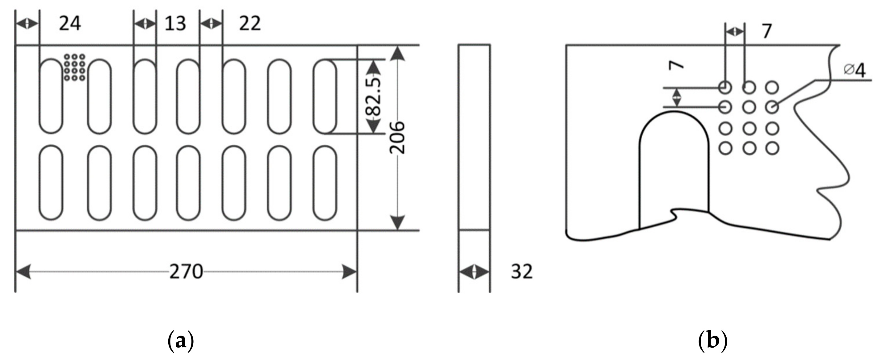
2. Experimental Setup

In the drilling experiments, the compacted graphite iron (CGI) workpiece plates (270-mm length, 206-mm width, and 32-mm thickness) were used. In order to optimize castability and mechanical properties of CGI, the material chemical composition has more than 80% pearlite, contains maximum 0.015% titanium, maximum 0.10% chromium, and maximum 0.40% manganese. The mechanical properties of CGI are 420 MPa in ultimate tensile stress, 140 GPa elastic modulus, and 210–265 BHN in hardness. For each CGI plate, the casting surface was machined at 1 mm for obtaining the flat surface and eliminating the heterogeneous part of the casting material. In the experiments, 25-mm depth holes were drilled and the tool wear was measured. Figure 1 shows the dimension and holes layout of the CGI plate, which is used in the drilling experiment.
The drill is a fine-grain carbide twist drill (B255A04000YPC KCK10, Kennametal, PA, USA). It has multi-layers (AlCrN base layer, TiAlN/AlCrTiN middle layers, and AlCrN outer layer) obtained by the drill supplier Kennametal. The diameter of the drill is 4 mm in diameter and the point angle is 135°. This drill has special designs with three margins, two through-the-drill 0.7-mm diameter holes, and an S-shape chisel. The top and side views of the drill are shown in Figure 2.
The drilling experiments were carried on a vertical machining center (Model 4020 by Fadal, Troy, MI, USA) shown in Figure 3. The single channel MQL system was mounted on the machine center made by UNIST, USA. The MQL system utilizes a high-speed air stream of compressed air to atomize the lubricant and blow it to the cutting area for cooling and lubrication. The compressed air (690 kPa) was applied in dry and MQL conditions. In the MQL condition, the Coolube 2210EP by UNIST was used for the cutting fluid.
In order to compare the drilling machinability under different lubrication conditions, four experiments, marked as Experiment I, II, III, and IV, are conducted (Table 1). In Experiment I–IV, dry, air, 5 mL/h MQL, and 20 mL/h MQL, were applied as lubrication, respectively. For comparing the tool wear mechanism, grey cast iron is drilled under a 5 mL/h MQL lubrication condition and marked as Experiment V. In the experiments with MQL, the cutting fluid 2210 EP (Unist Inc., Grand Rapids, MA, USA) was also applied. All of the experiments were conducted at a feed rate of 0.2 mm/rev and a constant cutting speed of 100 m/min. The spindle speed is 7961 rpm (the maximum spindle speed is 15,000 rpm). The number of holes before the drill breakage represents the drill life in Table 1.
The tool wear was measured after every 150 holes until 900 holes were drilled. After this, the tool wear was measured after every 300 holes. The tool wears were magnified 100 times and observed by using an optical microscope. The Philips XL 30 with an integrated energy dispersive X-ray spectroscopy (EDS) system was applied to obtain the scanning electron microscope (SEM) picture and analyze the elements of the worn drill.
In order to obtain the cutting load during the drilling process, a two-components dynamometer (type 9271A, Kistler, Switzerland), which can measure the torque and thrust force, was adopted. The amplifier and the software developed by LabVIEW were applied to process and store the testing data. When measuring the cutting load in different holes, the small CGI plate was cut out from the CGI plate (shown in Figure 3) and mounted to the dyno. In every 300 holes, the torque and thrust force were measured for each experiment.

3. Results and Discussion

3.1. Tool Wear

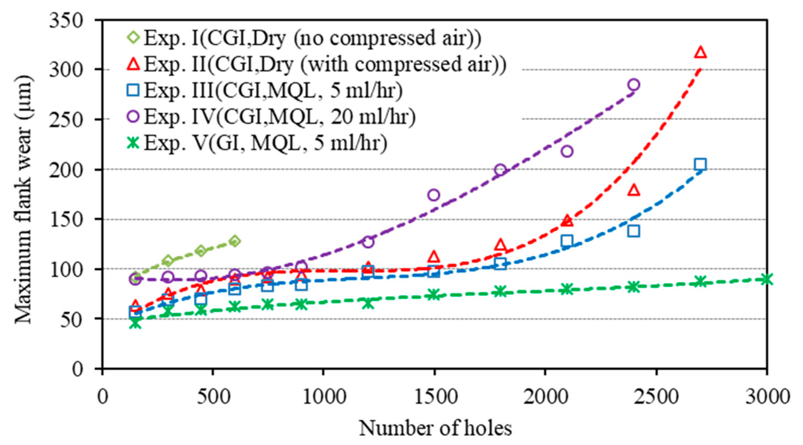
3.1.1. Maximum Flank Wear

Since the flank surface is directly related to the tool wear and tool life, the maximum flank wear of the drilling was investigated in this paper. Figure 4 illustrates the maximum flank wear in Experiment I to V.
From Figure 4, we know that the tool wear in Experiment I increases linearly with the number of holes before the drill is broken. In Experiment II and III, the process of tool wear can be divided into three phases: break in the period (0–900 holes), steady state wear region (90–2100 holes), and failure region (2101-drill broken). The tool life in the first four experiments is 639 holes, 2969 holes, 2948 holes, and 2685 holes, respectively. The tool life in Experiment I is the shortest. This is because, in Experiment I, there is no lubrication and the maximum flank wear is higher than those in Experiments II–IV. Furthermore, in the first 1800 holes in Experiment II and Experiment III, the flank wear of the latter is slightly lower than the former. After that, the differences of flank wears in these two experiments grow bigger. These differences indicate that, when applying the MQL (5 mL/h), the lubrication condition has been improved and the wear has been reduced. However, if the spray speed of MQL changes to 20 mL/h, the friction between the tool and the workpiece cannot be improved. As shown in Figure 4, the maximum flank wear and wear rate in Experiment IV is higher than that in Experiments II and III. The mixture of oil and dust chips in Experiment IV is difficult to eject, which causes higher tool wear. In conclusion, the good chip evacuation and the lubrication of the oil could lead to the lowest tool wear (Experiment III).
In addition, after measuring the cutting length in those experiments, the cutting length in Experiment I was found to be the shortest (16 m) when comparing to the ones obtained from Experiments II and III (74.2 m and 73.7 m). The results of cutting length are inconsistent with the results of tool wear. There are two reasons: the lowest flank wear in Experiment III is caused by the lubrication of the oil and the longest cutting length in Experiment II is brought about by the stability of the compressed air by giving rise to continuous chip evacuation. Compared to the experimental results of compressed air, the tool life under the MQL condition is lower because of the instability of the MQL compressed air. The instability is caused by the power consumption for generating the oil droplet.
In Experiment V, the GI plate is drilled. It can be observed from Figure 4 that the tool wear and wear rate in drilling GI is lower than in drilling CGI. After 3000 holes, the maximum flank wear in Experiment I is still small (less than 100 micron). If the tool wear in drilling GI has a linear relationship with the number of holes, another 3000 holes could be drilled before the tool wear reaches 150 micron. GI has good machinability in the drilling process when compared with CGI.

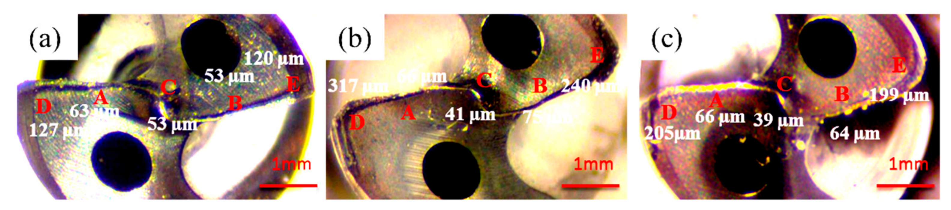
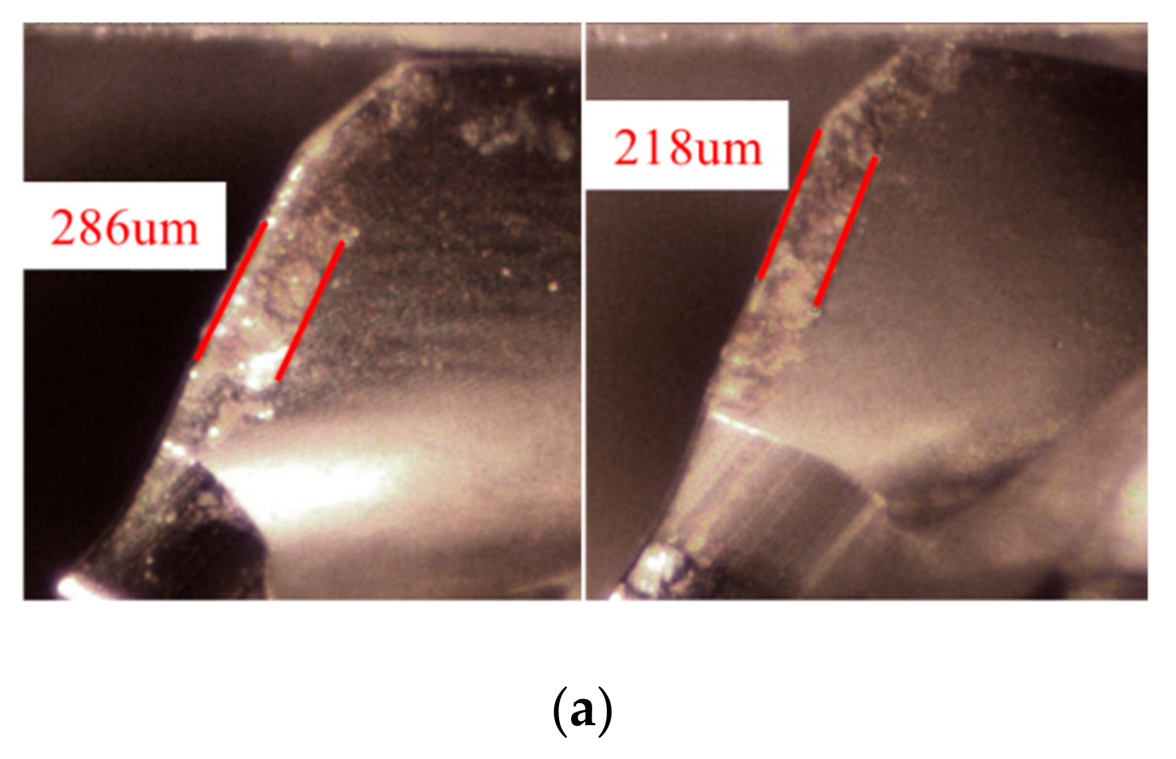
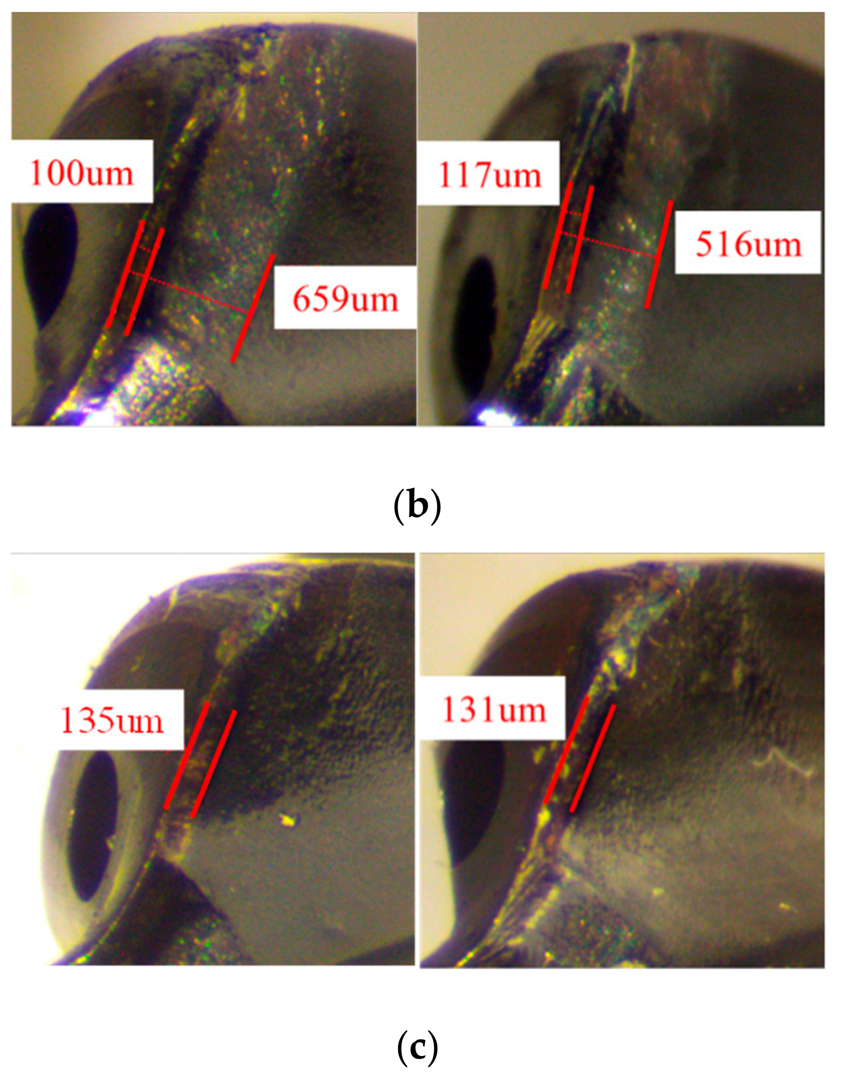
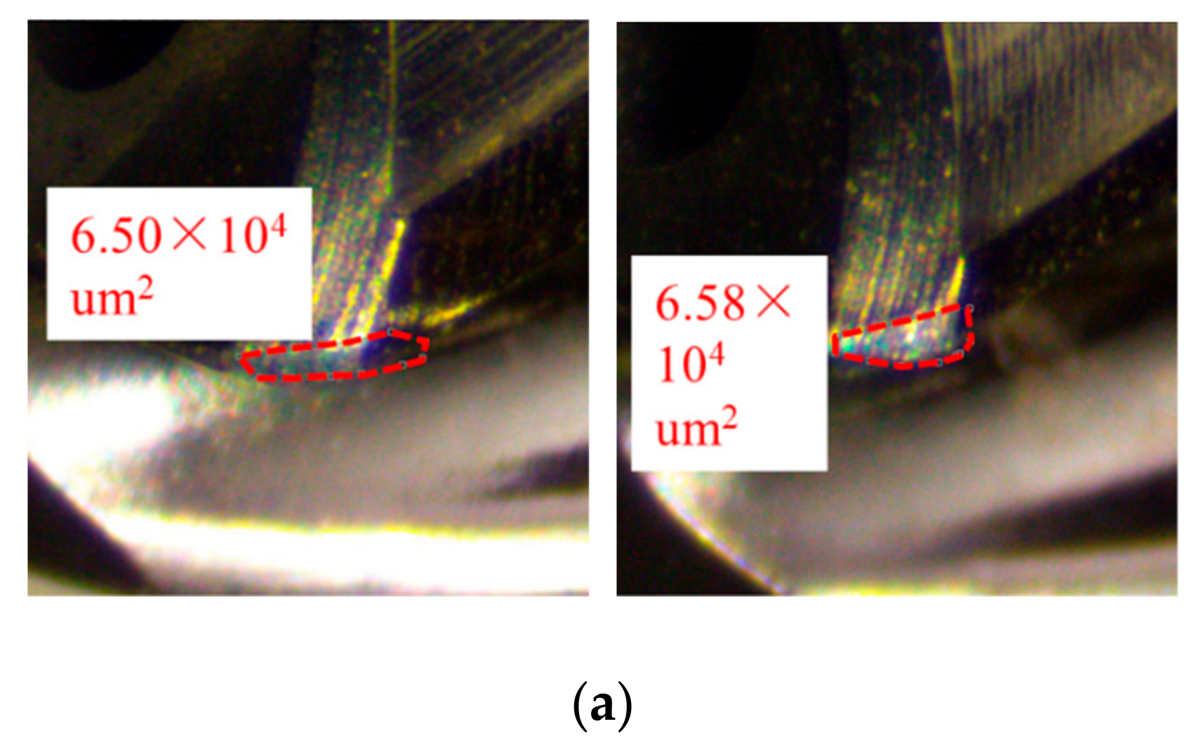
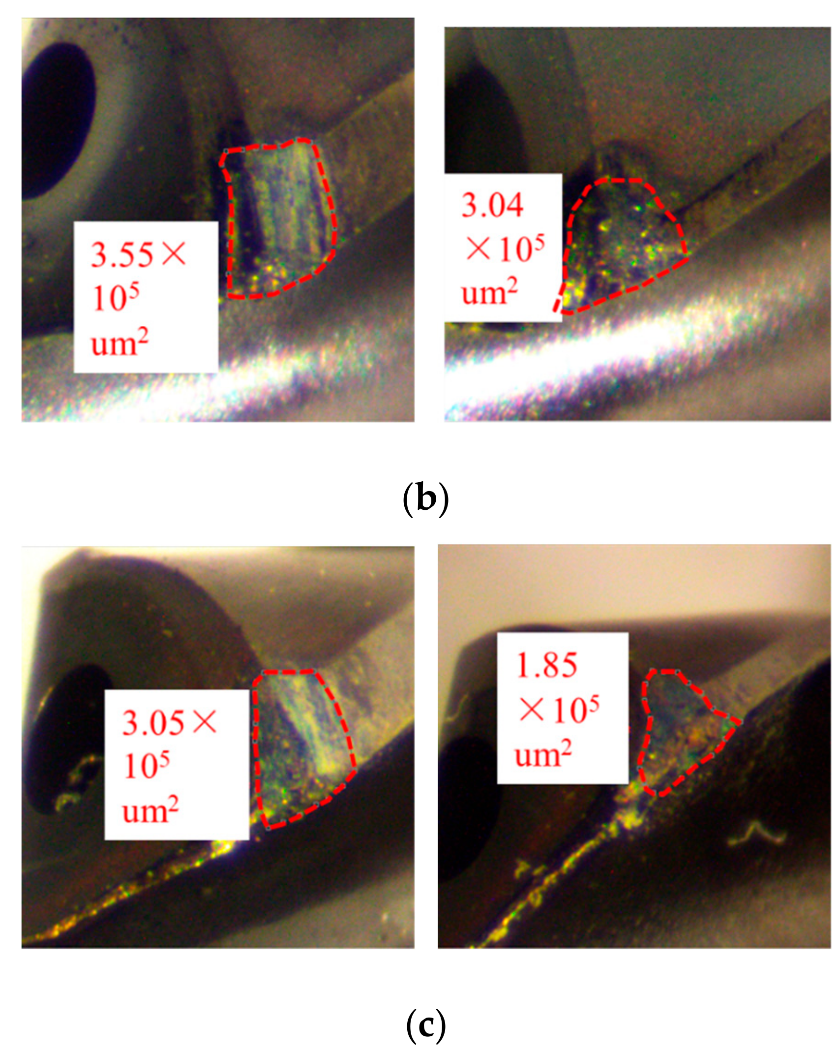
3.1.2. The Worn Drills

Figure 5, Figure 6 and Figure 7 show the flank wear, crater wear, and margin wear of the worn drills in Experiments I–III at the point before being broken.
Figure 5 presents the flank wears of three worn drills at five points in Experiments I–III, respectively. Flank wear occurs along the relief surface of the cutting edges and it is primarily caused by abrasive wear. The scratch can also be observed near point D in Experiment II and III as a result of abrasive wear. From Figure 5, it can be concluded that tool wear at five points increased with the distance from the center of the drill. Points D and E are far from the center of the drill and have the largest tool wear. The tool wears at points A and B are smaller than that at points D and E. In addition, they are almost the same. The wear rate at point C, which is situated at the chisel edge, is the lowest. The scratch can also be observed near point D in Experiment II and III as a result of abrasive wear.
Figure 6 illustrates the crater wears of three worn drills. The crater wears occur on the flute face near the cutting edges. The widths of crater wears in Experiment I are 286 um and 218 um, which are more than in Experiment II and III. It can be observed from Experiment II that there are two regions of crater wear due to the friction of the compressed air coming out of the through-the-drill hole close to the cutting edge. The width of the first region is about 100 microns and the width of the second region is more than 500 microns. By contrast, there is only one reign of the crater wear in Experiment III and the width is approximately 130 microns. It is wider than the first region and thinner than the second region in Experiment II. The oil, which helps reduce the friction between the drill and workpiece, can be clearly observed on both flutes of the drill.
The margin wears of three worn drills, which occur on the outer corner of the cutting edges, are demonstrated in Figure 7. The area of the margin is used to evaluate the level of the margin wear. At the margin region, the peripheral speed is the highest. Increasing the cutting speed could increase the cutting temperature, which further causes the hardness of the drill material to drop. As a result, the main wears are abrasion, thermal softening, and diffusion in the margin region. Thermal softening not only leads to the increased abrasive wear, but also results in plastic deformation of the cutting edges. The latter would further aggravate the drill abrasion. After drilling 600 holes in Experiment I, the wear area of the two margins are 6.5 × 10⁴ and 6.58 × 10⁴ um2, respectively. Apart from the heat effect zone in Experiment I, the chipping and abrasion can be clearly seen in the margin of the drill in both Experiment II and Experiment III. Compared with the margin wears in the other two experiments, the wear areas of two margins in Experiment II (3.55 × 10⁵ and 3.04 × 10⁵ um2) are larger.
In conclusion, oil produced by the MQL system can be spread to the cutting drill, but only a little oil reaches the margin area. Therefore, more oil in Experiment III cannot reduce the friction between the margin and the wall of the hole. However, the pressure of the compressed air decreases due to producing more oil in Experiment III, which results in reducing the effect of the chip evacuation. Thus, the larger torque and force may occur in Experiment III. This can explain why there is lower tool wear and shorter tool life in Experiment III than in Experiment II.

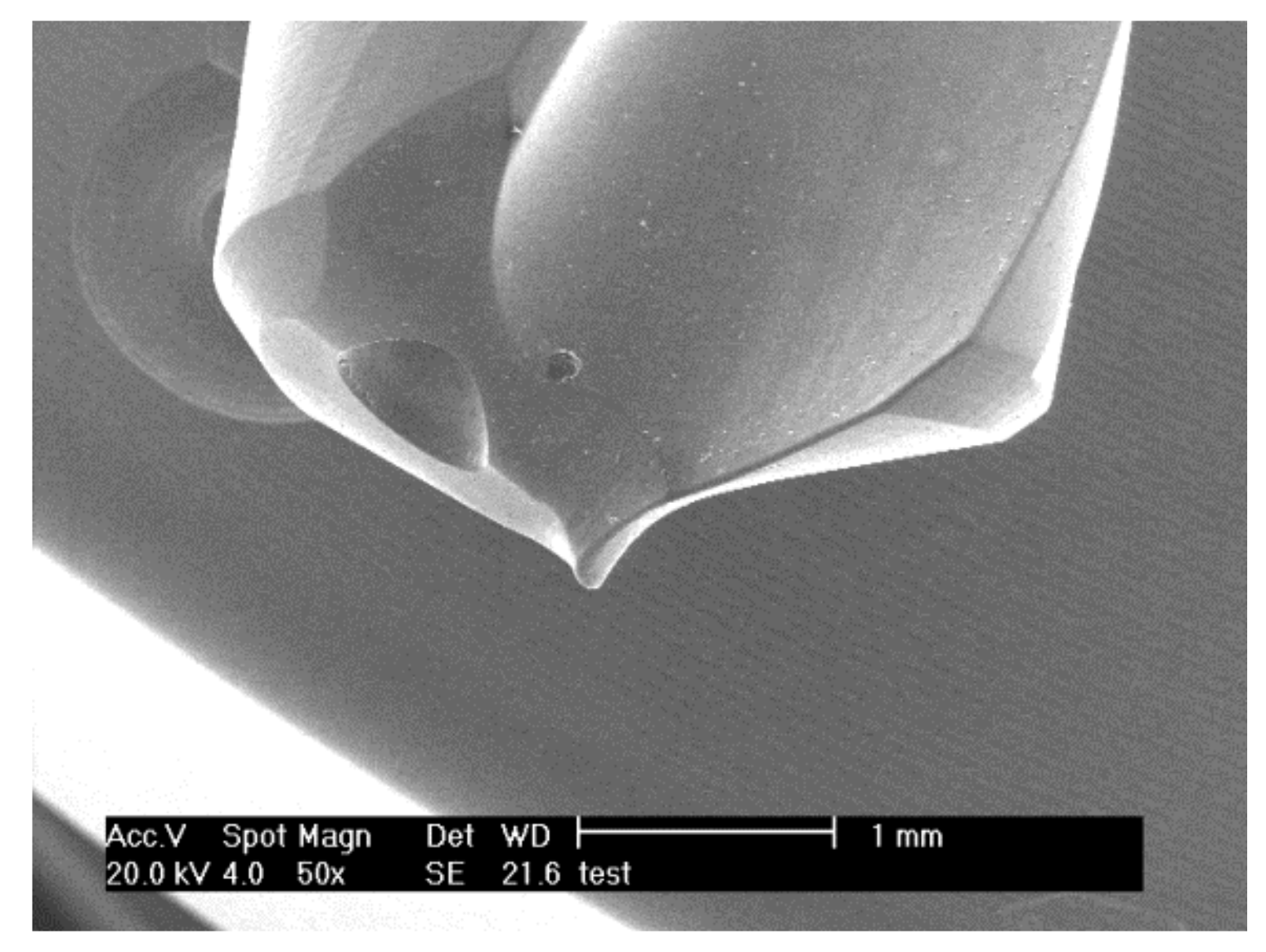
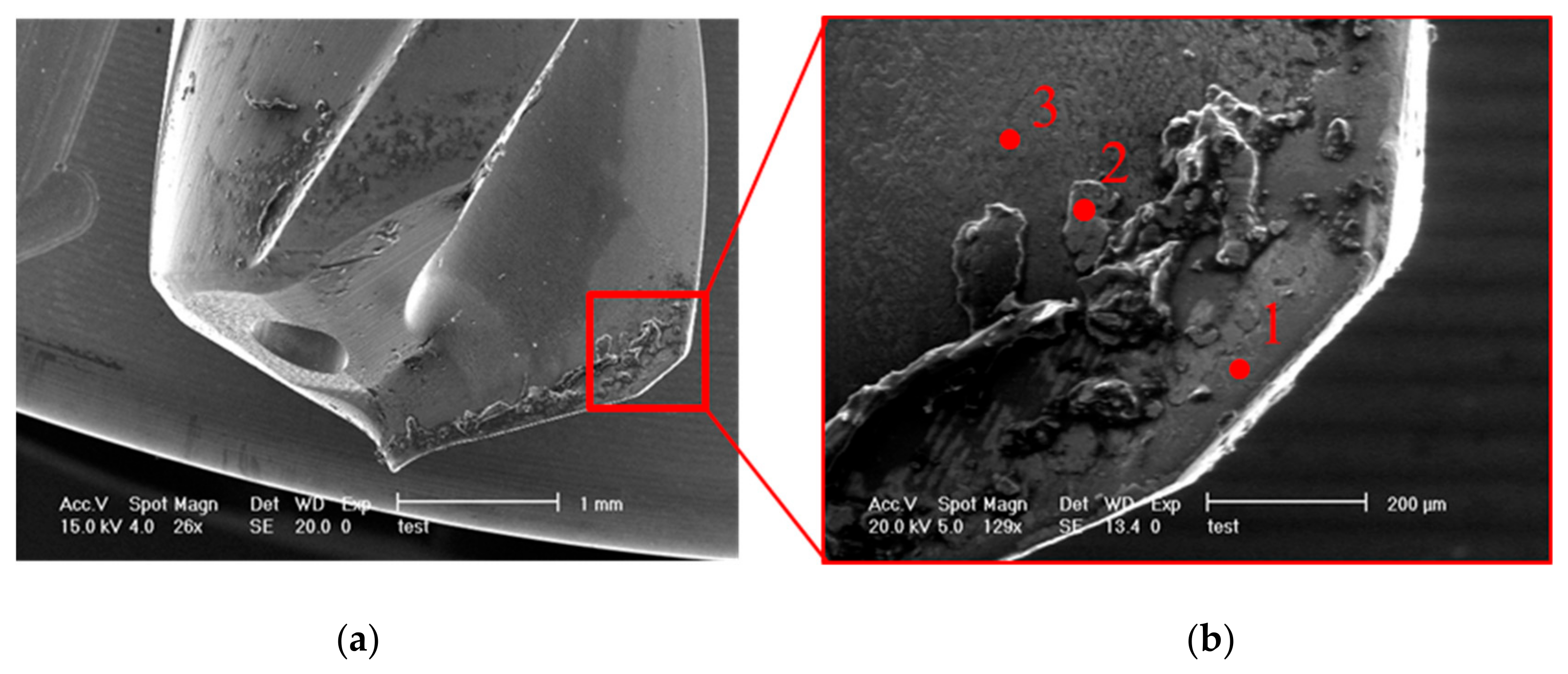
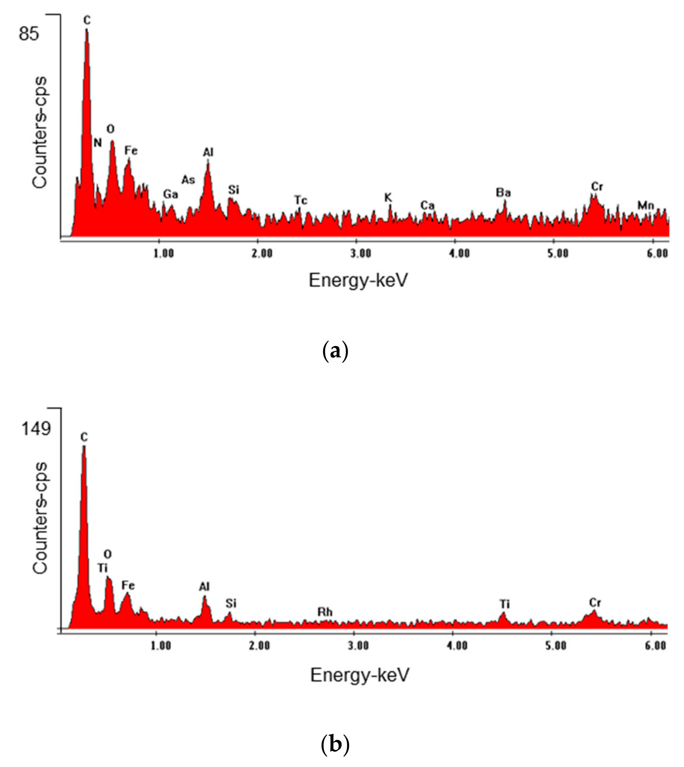
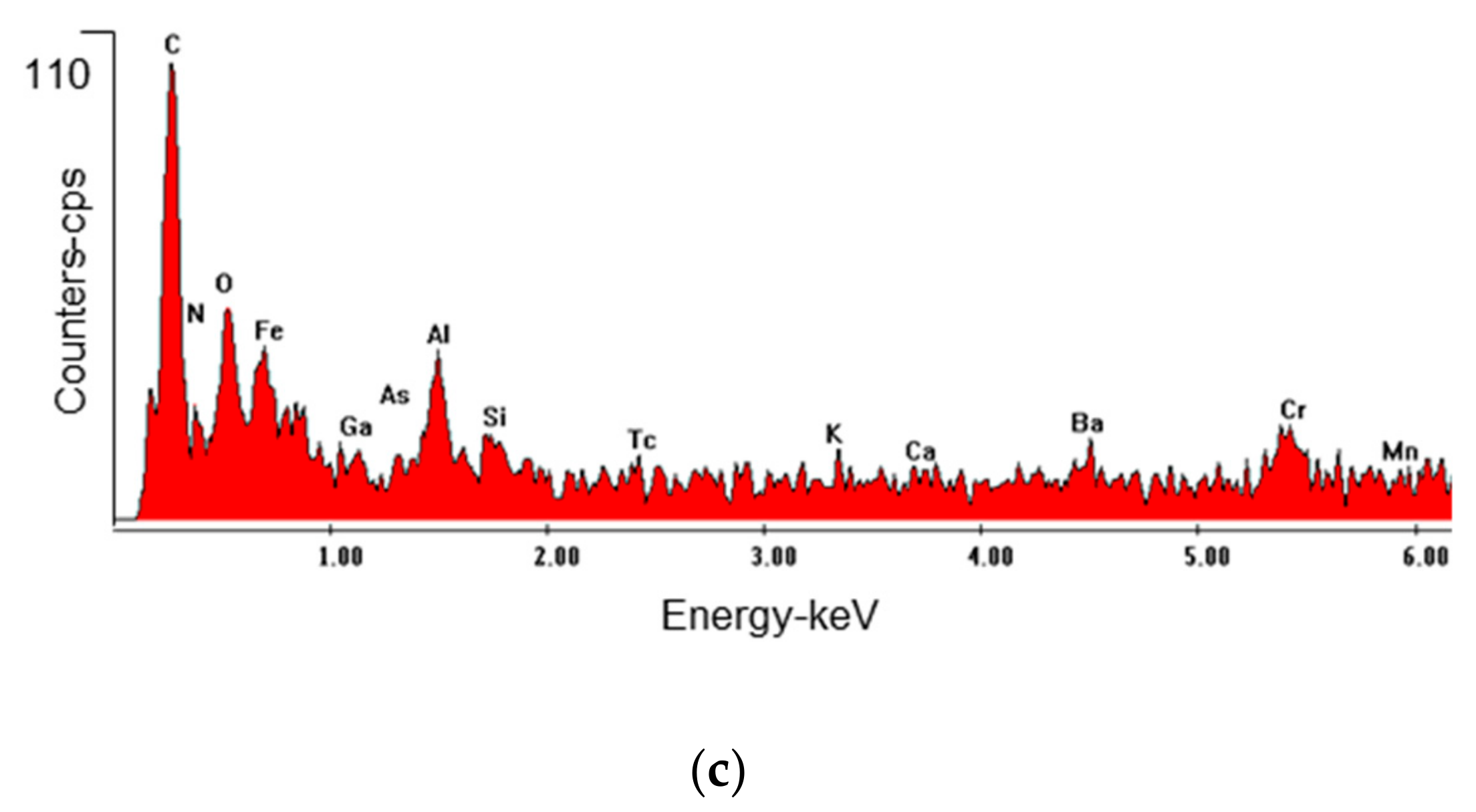
3.2. Scanning Electron Microscope (SEM) and Energy Dispersive Spectrometer (EDS) Results

The rake face of the drill contacts the chip in the drilling process. The diffusion and adhesion can easily come up in these zones due to the high contact pressure. The SEM picture of the new drill is shown in Figure 8. In the present work, the worn drills after 900 holes were selected for SEM and for the analysis of the elements at the cutting edge using EDS. The rake face SEM pictures of the worn drill in Experiment II is shown in Figure 9.
When compared with the new drill, it can be observed that some layered films are put on the rake face. Since CGI is a relatively brittle cast iron and it is very difficult to form this kind of layered films, such layered films should be the broken coating layers. Three points in different regions of the film are selected and detected by EDS to identify its element. Figure 10 presents the results of EDS at point 1, 2, and 3, respectively.
From the EDS spectra above, the integrated coating can be found in this zone. Comparing Figure 10a with Figure 10c, it can be inferred that the elements at point 1 and point 3 are similar. At the two points, a high concentration of nitrogen and carbon can be detected. Carbon is the major element of graphite, which originates from the workpiece material. Nitrogen is the main element of the coating layer. Oxygen and iron are also the key chemical elements, according to the figure. Iron is the main element of the workpiece material. It means that the adhesion occurs in the drilling process. Aluminum and chromium are also detected at these two points. They may come from the coating material. As shown in Figure 10b, the elements of the middle coating layers, such as titanium, aluminum, chromium, and nitrogen, are observed at point 2. Meanwhile, the major elements of the workpiece material (iron, carbon, and silicon) are also detected according to the results of EDS. There is an adhesion between the drill and workpiece at this point.
In Section 2, the multilayers coating in this drill have been introduced in detail. They are the AlCrN base layer, the TiAlN/AlCrTiN middle layers, and the AlCrN outer layer. Comparing the results of EDS at point 1, 2, and 3 with the elements of the base layer, middle layers, and outer layer, it can be concluded that the layered film at point 2 is the middle layer (TiAlN/AlCrTiN). The coating at point 3 has a good reservation and is the outer layer. Point 1 and point 3 have basically the same elements. However, the visible damage of the coating can be easily observed at point 1. Therefore, the coating at point 1 should be the base layer (AlCrN). In addition, C and Fe can be detected at all three points and the content of carbon is clearly more than iron. Carbon in the films can be utilized as lubricant in the drilling process.

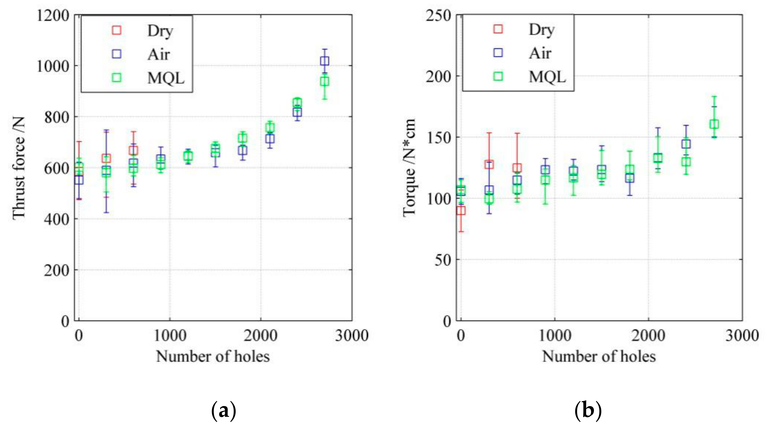
3.3. Torque and Force

3.3.1. Error Line of Torque and Thrust Force

Figure 11 shows the error line results of torque and thrust force during the drilling process in Experiments I–III.
Due to the higher wear rate, the torque and thrust force in Experiment I are higher than that in Experiments II and III. The thrust forces in Experiments II and III are exponentially increased with the number of holes and are basically similar. In the break in stage (0–900 holes), the changes of thrust force amplitude are bigger. The thrust force in the steady state wear stage (900–2100 holes) is stable. In the failure region (2101–tool break), the changes of thrust force amplitude are slightly increased when compared with the front stage. The torques tested in those three experiments have a strong relationship with the results of tool wear. Similar to the thrust force, the torque in Experiment I have the largest amplitude changes. The changes of the torques in Experiment II and III are stable. The changing trend and average values of the torque in these two experiments are almost the same in the whole drilling process. At the 2700th hole, the lower thrust force can be found when the tool wear is lower. However, the maximum torque at this hole in Experiment III is larger than that in Experiment II.

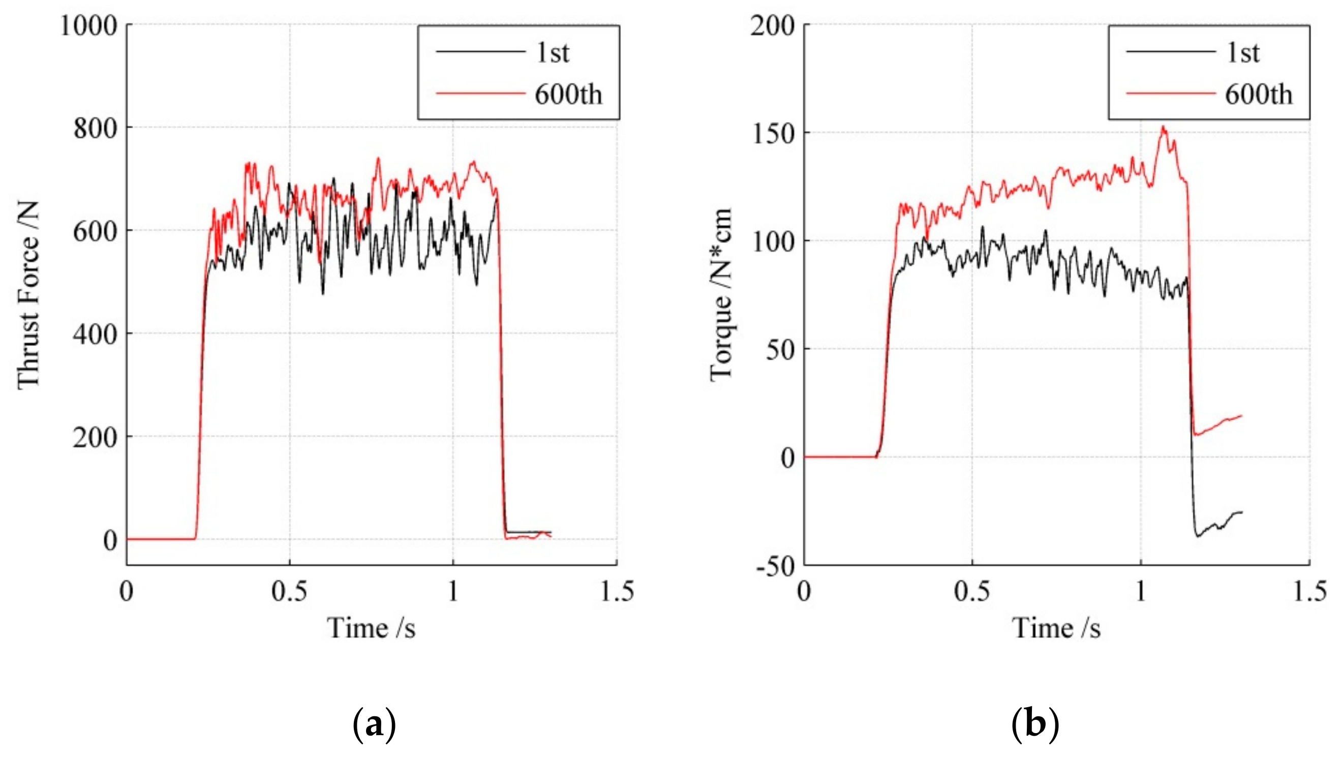
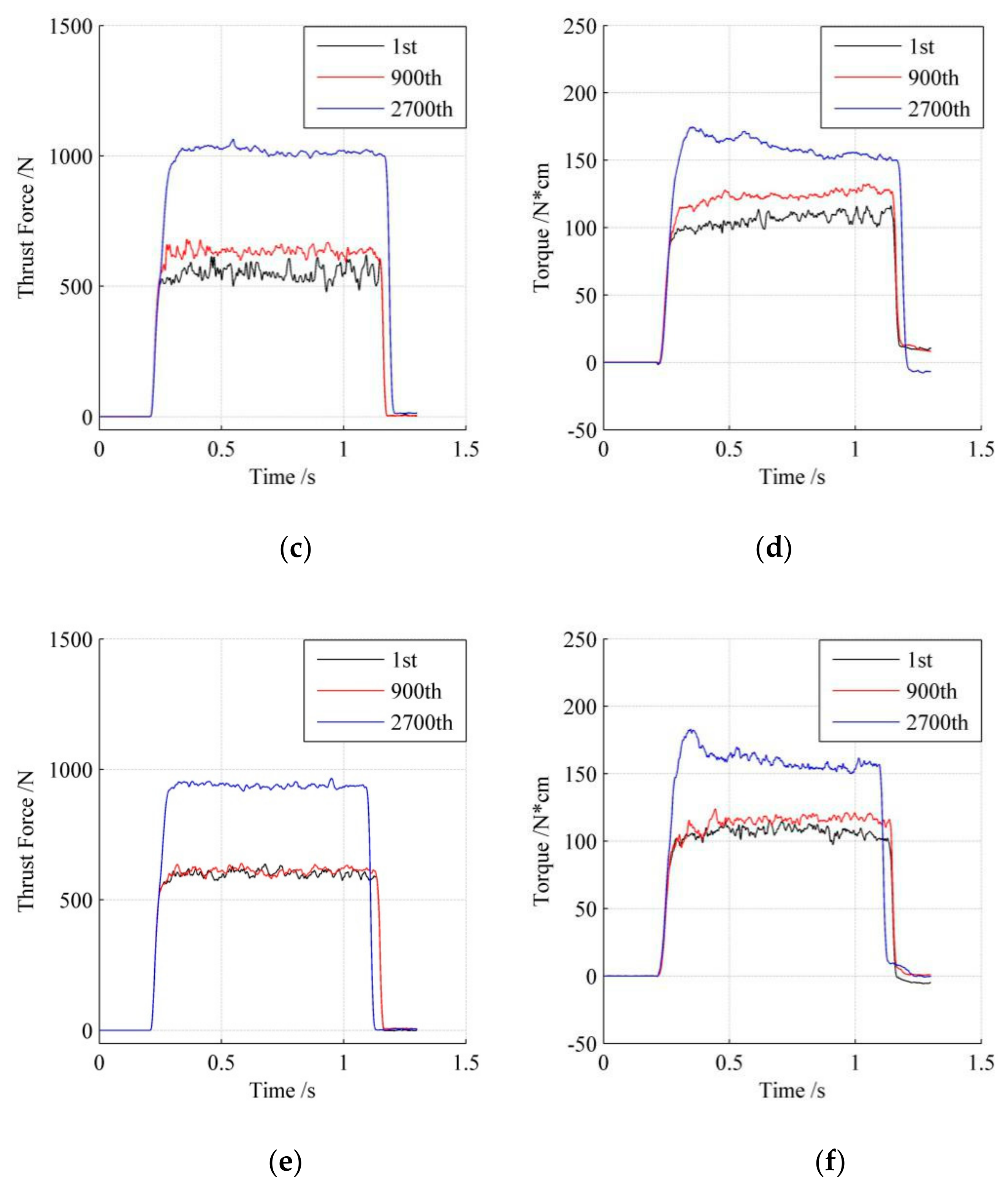
3.3.2. Cutting Loads

The changes of cutting loads with the number of holes in Experiments I, II, and III are investigated. The results are shown in Figure 12.
Being affected by the chips in the holes, the cutting loads are unstable in Experiment I, as shown in Figure 12a,b. With the increase of holes, the tool wear is getting worse and worse. The torque and the thrust force are increased as well. After drilling 600 holes, the fluctuations of the lines are reduced, which means the thrust force becomes more stable. In addition, the thrust force at a specific hole does not change greatly with the drilling depth. However, by contrast, it is clear that the torque is changing (increasing at the beginning and decreasing at 600 holes) when the tool is drilling through a hole.
The thrust force in Experiment II, as shown Figure 12c, is lower and more stable than that in Experiment I. This is because, in Experiment II, the chip ejection caused by the compressed air, which comes out from the through-the-drill holes, is very effective. Similarly, as the number of holes increases, the torque and thrust force are both increased due to the increment of tool wear. At the beginning of the drilling experiment, the thrust force and torque are about 550 N and 100 N*cm. At the 2700th hole, the thrust force and torque are more than 1000 N and 150 N*cm. From Figure 12d, it can be seen that the torque at the 1st and 900th holes have slightly increased with the depth of holes. It can be explained that the friction between the margin of the drill and the wall of the hole are increased with the depth of the hole. However, the decrement of torque with the drilling depth can be observed at the 2700th hole, which may be caused by the burr formation for the large flank wear.
Figure 12e,f present the torque and thrust force in Experiment III. Both torque and thrust force in Experiment III are lower and more stable than that in Experiment II. This is because the oil in Experiment III can improve the lubrication between the drill and workpiece material, which further leads to lower tool wear. However, the torque at the start stage of the 2700th hole (180 N*cm) is higher than that in Experiment II (170 N*cm). Therefore, the tool life in Experiment III is shorter than that in Experiment II. After the 2700th hole, the torque in Experiment III falls quickly and becomes lower than that in Experiment II. In conclusion, because of the lubrication of oil in Experiment III, the lower and more stable cutting loads can be obtained while the hole is drilling.

4. Conclusions

The drilling machinability of CGI under different lubrication conditions are investigated in this paper. The maximum flank wear and tool wear at five points along the cutting edge are measured and investigated at first. The wear mechanism is then studied based on the SEM and EDS results. Lastly, the cutting loads during the drilling process are measured. Several conclusions for drilling CGI are summarized below.
1. Drilling of CGI under dry conditions (with compressed air) and MQL 5 mL/h is feasible. Drilling of CGI with compressed air leads to longer tool life and lower tool wear than under a dry condition, because the compressed air strongly improves the ability of chip evacuation. Drilling of CGI with MQL (5 mL/h) has the smallest tool wear due to the lubrication of oil. The small amount of oil under the MQL condition (5 mL/h) can improve the lubrication of the drilling procedure, which results in the lower tool wear and cutting loads. However, the large amount of oil (20 mL/h) can mix with the dust chip to slow the movement of chips.
2. Adhesion and abrasion wear are the main mechanisms of drilling CGI. Severe abrasion wear when drilling CGI under a dry condition occurs due to the hard dust chip, which is very difficult to eject through good geometry of a drill. Under compressed air, the chip ejection was greatly improved. Therefore, the adhesion becomes the vital reason for the tool wear.
3. Carbon, which originates from the graphite of CGI, can improve the lubrication in the drilling process when compared with MnS in drilling grey cast iron. This makes the dry drilling of CGI with compressed air feasible.
4. The multi-layers coating of the drill is useful for drilling CGI. This kind of coating is effective to prevent the friction between tool material and workpiece material. After the breakage of the coating, the tool wear rate is increased rapidly and the tool runs into the failure stage.

Author Contributions

Conceptualization, Y.L. and W.W. Methodology, W.W. Investigation, W.W. Data curation, W.W. Writing—original draft preparation, Y.L. Writing—review and editing, W.W.

Funding

The National Science Foundation of China (Grant No. 51705402), Natural Science Basic Research Plan in Shaanxi Province of China (Program No. 2019JM-148), and National Science and Technology Major Project of China (No. 2017ZX04013001) funded this research.

Acknowledgments

We thank the Ford Motor Company, UNIST, and Kennametal for their support.

Conflicts of Interest

The authors declare no conflict of interest.

References

  1. Dawson, S.; Schroeder, T. Practical applications for compacted graphite iron. AFS Trans. 2004, 112, 1–9. [Google Scholar]
  2. Gastel, M.; Konetschny, C.; Reuter, U.; Fasel, C.; Schulz, H.; Riedel, R.; Ortner, H.M. Investigation of the wear mechanism of cubic boron nitride tools used for the machining of compacted graphite iron and grey cast iron. Int. J. Refract. Met. Hard 2000, 18, 287–296. [Google Scholar] [CrossRef]
  3. Evans, R.; Hoogendoorn, F.; Platt, E. Lubrication & Machining of Compacted Graphite Iron. AFS Trans. 2001, 1–8. [Google Scholar]
  4. Kuzu, A.T.; Bijanzad, A.; Bakkal, M. Experimental Investigations of Machinability in the Turning of Compacted Graphite Iron using Minimum Quantity Lubrication. Mach. Sci. Technol. 2015, 19, 559–576. [Google Scholar] [CrossRef]
  5. Dawson, S.; Hollinger, I.; Robbins, M.; Daeth, J.; Reuter, U.; Schulz, H. The effect of metallurgical variables on the machinability of compacted graphite iron. SAE Trans. 2001, 110, 334–352. [Google Scholar]
  6. Nayyar, V.; Alam, M.Z.; Kaminski, J.K.; Kinnander, A.; Nyborg, L. An Experimental Investigation of the Influence of Cutting Edge Geometry on the Machinability of Compacted Graphite Iron. Int. J. Mech. Mater. Eng. 2013, 3, 1–25. [Google Scholar] [CrossRef]
  7. Abele, E.; Burkhard, S. Using PCD for machining CGI with a CO2 coolant system. Prod. Eng. 2008, 2, 165–169. [Google Scholar] [CrossRef]
  8. Rosa, S.D.; Diniz, A.E.; Andrade, C.L.; Guesser, W.L. Analysis of tool wear, surface roughness and cutting power in the turning process of compact graphite irons with different titanium content. J. Braz. Soc. Mech. Sci. 2010, 32, 234–240. [Google Scholar] [CrossRef]
  9. Da Silva, M.B.; Naves, V.T.; De Melo, J.D.; de Andrade, C.L.F.; Guesser, W.L. Analysis of wear of cemented carbide cutting tools during milling operation of gray iron and compacted graphite iron. WEAR 2011, 271, 2426–2432. [Google Scholar] [CrossRef]
  10. De Oliveira, V.V.; Beltrao, P.A.; Pintaude, G. Effect of tool geometry on the wear of cemented carbide coated with TiAlN during drilling of compacted graphite iron. WEAR 2011, 271, 2561–2569. [Google Scholar] [CrossRef]
  11. Gabaldo, S.; Diniz, A.E.; Andrade, C.L.; Guesser, W.L. Performance of carbide and ceramic tools in the milling of compact graphite iron—CGI. J. Braz. Soc. Mech. Sci. 2010, 32, 511–517. [Google Scholar] [CrossRef]
  12. Alves, S.M.; Schroeter, R.B.; Bossardi, J.C.; de Andrade, C.L.F. Influence of EP additive on tool wear in drilling of compacted graphite iron. J. Braz. Soc. Mech. Sci. 2011, 33, 197–202. [Google Scholar] [CrossRef] [Green Version]
  13. Mocellin, F.; Melleras, E.; Guesser, W.L.; Boehs, L. Study of the machinability of compacted graphite iron for drilling process. J. Braz. Soc. Mech. Sci. 2004, 26, 22–27. [Google Scholar] [CrossRef]
  14. Paiva, J.M.; Amorim, F.L.; Soares, P.; Torres, R.D. Evaluation of Hard Coating Performance in Drilling Compacted Graphite Iron (CGI). J. Mater. Eng. Perform. 2013, 22, 3155–3160. [Google Scholar] [CrossRef]
  15. Nayyar, V.; Kaminski, J.K.; Kinnander, A.; Nyborg, L. An Experimental Investigation of Machinability of Graphitic Cast Iron Grades; Flake, Compacted and Spheroidal Graphite Iron in Continuous Machining Operations. Procedia Cirp 2012, 1, 488–493. [Google Scholar] [CrossRef]
  16. Heck, M.; Ortner, H.M.; Flege, S.; Reuter, U.; Ensinger, W. Analytical investigations concerning the wear behaviour of cutting tools used for the machining of compacted graphite iron and grey cast iron. Int. J. Refract. Met. Hard 2008, 26, 197–206. [Google Scholar] [CrossRef]
  17. Quinto, D.T. Twenty-five years of PVD coatings at the cutting edge. SVC Bull. 2007, 17–22. [Google Scholar]
  18. Kuzu, A.T.; Berenji, K.R.; Bakkal, M. Thermal and force modeling of CGI drilling. Int. J. Adv. Manuf. Technol. 2016, 82, 1649–1662. [Google Scholar] [CrossRef]
  19. Kuzu, A.T.; Berenji, K.R.; Ekim, B.C.; Bakkal, M. The thermal modeling of deep-hole drilling process under MQL condition. J. Manuf. Process. 2017, 29, 194–203. [Google Scholar] [CrossRef]
  20. Wu, W.; Kuzu, A.T.; Stephenson, D.A.; Hong, J.; Bakkal, M.; Shih, A. Dry and minimum quantity lubrication high-throughput drilling of compacted graphite iron. Mach. Sci. Technol. 2018, 22, 652–670. [Google Scholar] [CrossRef]
  21. Da Mota, P.R.; Reis, A.M.; Machado, A.R.; Ezugwu, E.O.; da Silva, M.B. Tool wear when tapping operation of compacted graphite iron. Proc. Inst. Mech. Eng. B J. Eng. 2013, 227, 1704–1713. [Google Scholar] [CrossRef]
Figure 1. Dimension and hole layout of the CGI plate (Unit: mm). (a) The dimension of the CGI plates, and (b) holes layout.
Metals 09 01095 g001
Figure 2. The drill applied in the experiments: (a) Top view, (b) side view 1, and (c) side view 2. Reproduced from [20], with permission from Taylor & Francis.
Metals 09 01095 g002
Figure 3. Drilling experiment setup.
Metals 09 01095 g003
Figure 4. The maximum flank wears in five experiments. Reproduced from [20], with permission from Taylor & Francis.
Metals 09 01095 g004
Figure 5. The flank wears of three worn drills: (a) Experiment I (600th hole), (b) Experiment II (2700th hole), and (c) Experiment III (2700th hole). Reproduced from [20], with permission from Taylor & Francis.
Metals 09 01095 g005
Figure 6. The crater wears of three worn drills: (a) Experiment I (600th hole), (b) Experiment II (2700th hole), and (c) Experiment III (2700th hole).
Metals 09 01095 g006aMetals 09 01095 g006b
Figure 7. The margin wears of three worn drills: (a) Experiment I (600th hole), (b) Experiment II (2700th hole), and (c) Experiment III (2700th hole).
Metals 09 01095 g007aMetals 09 01095 g007b
Figure 8. The SEM of one new drill.
Metals 09 01095 g008
Figure 9. The SEM pictures for the worn drill after 900 holes in Experiment II: (a) SEM picture, and (b) SEM picture for EDS.
Metals 09 01095 g009
Figure 10. The EDS results at three points: (a) Point 1, (b) point 2, and (c) point 3.
Metals 09 01095 g010aMetals 09 01095 g010b
Figure 11. The error line results of cutting loads in three Experiments: (a) Thrust force and (b) torque.
Metals 09 01095 g011
Figure 12. The cutting loads of three Experiments at different holes: (a) Thrust forces in Experiment I, (b) torques in Experiment I, (c) thrust forces in Experiment II, (d) and torques in Experiment II. (e) Thrust forces in Experiment III, and (f) torques in Experiment III. Reproduced from [20], with permission from Taylor & Francis.
Metals 09 01095 g012aMetals 09 01095 g012b
Table 1. Five drilling experiments.
Exp.Workpiece MaterialLubrication ConditionDrill Life
ICGIDry (no compressed air)639
IICGIDry (with compressed air)2969
IIICGIMQL, 5 mL/h2948
IVCGIMQL, 20 mL/h2685
VGIMQL, 5 mL/h>3000

